1
LBI-38715A
Mobile Communications
C3 MAESTRO
CONSOLE SYSTEM
TABLE OF CONTENTS
AUDIO PA BOARD . . . . . . . . . . . . . . . . . . . . . . . LBI-38716
MATRIX BOARD . . . . . . . . . . . . . . . . . . . . . . . . LBI-38717
I/O BOARD . . . . . . . . . . . . . . . . . . . . . . . . . . . LBI-38718
VOLUME CONTROLLER BOX . . . . . . . . . . . . . . . . . . LBI-38719
LOGIC BOARD . . . . . . . . . . . . . . . . . . . . . . . . . LBI-38720
Printed in U.S.A
Maintenance Manual
LBI-38715
LBI-38715
Desk Microphone Input
TABLE OF CONTENTS
"DESK MIC HI"
SPECIFICATIONS . . . . . . . . . . . . . . . . . . . . . .
SYSTEM DESCRIPTION . . . . . . . . . . . . . . . . . .
C3 MAESTRO Console System (Figure 1) . . . . . . .
System I/O Diagram (Figure 2) . . . . . . . . . . . . .
OPERATING PROCEDURES . . . . . . . . . . . . . . . .
Cabling . . . . . . . . . . . . . . . . . . . . . . . . . .
Personal Computer (PC) . . . . . . . . . . . . . . . . .
Audio Tower . . . . . . . . . . . . . . . . . . . . . . .
Controls . . . . . . . . . . . . . . . . . . . . . . . . . .
Using The System . . . . . . . . . . . . . . . . . . . .
SPREADER BOARD . . . . . . . . . . . . . . . . . . . . .
CONSOLE PROGRAM INSTALLATION DATA . . . . .
SYSTEM TEST . . . . . . . . . . . . . . . . . . . . . . . .
PROBLEM RESOLUTION . . . . . . . . . . . . . . . . .
GLOSSARY OF ACRONYMS . . . . . . . . . . . . . . . .
SYSTEM INTERCONNECTION DIAGRAM . . . . . . .
AUDIO TOWER REAR PANEL . . . . . . . . . . . . . . .
SPREADER BOARD OUTLINE . . . . . . . . . . . . . .
SPREADER BOARD SCHEMATIC . . . . . . . . . . . . .
SPREADER BOARD PARTS LIST . . . . . . . . . . . . .
BACKPLANE PARTS LIST . . . . . . . . . . . . . . . . .
BACKPLANE OUTLINE . . . . . . . . . . . . . . . . . .
BACKPLANE SCHEMATIC . . . . . . . . . . . . . . . . .
AUDIO TOWER MECHANICAL PARTS BREAKDOWN
CONSOLE SYSTEM CONNECTORS . . . . . . . . . . .
.
.
.
.
.
.
.
.
.
.
.
.
.
.
.
.
.
.
.
.
.
.
.
.
.
.
.
.
.
.
.
.
.
.
.
.
.
.
.
.
.
.
.
.
.
.
.
.
.
.
.
.
.
.
.
.
.
.
.
.
.
.
.
.
.
.
.
.
.
.
.
.
.
.
.
.
.
.
.
.
.
.
.
.
.
.
.
.
.
.
.
.
.
.
.
.
.
.
.
.
.
.
.
.
.
.
.
.
.
.
.
.
.
.
.
.
.
.
.
.
.
.
.
.
.
.
.
.
.
.
.
.
.
.
.
.
.
.
.
.
.
.
.
.
.
.
.
.
.
.
.
.
.
.
.
.
.
.
.
.
.
.
.
.
.
.
.
.
.
.
.
.
.
.
.
.
.
.
.
.
.
.
.
.
.
.
.
.
.
.
.
.
.
.
.
.
.
.
.
.
.
.
.
.
.
.
.
.
.
.
.
.
.
.
.
.
.
.
.
.
.
.
.
.
.
.
.
.
.
.
.
.
.
.
.
.
.
.
.
.
.
.
.
.
.
.
.
.
.
.
.
.
.
.
.
.
.
.
.
.
.
.
.
.
.
.
.
.
.
.
.
.
.
.
.
.
.
.
.
.
.
.
.
.
.
.
.
.
.
.
.
.
.
.
.
.
.
.
.
.
.
.
.
.
.
.
.
.
.
.
.
.
.
.
.
.
.
.
.
.
.
.
.
.
.
.
.
.
.
.
.
.
.
.
.
.
.
.
.
.
.
.
.
.
.
.
.
.
.
.
.
.
.
.
.
.
.
.
.
.
.
.
.
.
.
.
.
.
.
.
.
.
.
.
.
.
.
.
.
.
.
.
.
.
.
.
.
.
.
.
.
.
.
.
.
.
.
.
.
.
.
.
.
.
.
.
.
.
.
.
.
.
.
.
.
.
.
.
.
.
.
.
.
.
.
.
.
.
.
.
.
.
.
.
.
.
.
.
.
.
.
.
.
.
.
.
.
.
.
.
.
.
.
.
.
.
.
.
.
.
.
.
.
.
.
.
.
.
.
.
.
.
.
.
.
.
.
.
.
.
.
.
.
.
.
.
.
.
.
.
.
.
.
.
.
.
.
.
.
.
.
.
.
.
.
.
.
.
.
.
.
.
.
.
.
.
.
.
.
.
.
.
.
.
.
.
.
.
.
.
.
.
.
.
.
.
.
.
.
.
.
.
.
.
.
.
.
.
.
.
.
.
.
.
.
.
.
.
.
.
.
.
.
.
.
.
.
.
.
.
.
.
.
.
.
.
.
.
.
.
.
.
.
.
.
.
.
.
.
.
.
.
.
.
.
.
.
.
.
.
.
.
.
.
.
.
.
.
.
.
.
.
.
.
.
.
.
.
.
.
.
.
.
.
.
.
.
.
.
.
.
.
.
.
.
.
.
.
.
.
.
.
.
.
.
.
.
.
.
.
.
.
.
.
.
.
.
.
.
.
.
.
.
.
.
.
.
.
.
.
.
.
.
.
.
.
.
.
.
.
.
.
.
.
.
.
.
.
.
.
.
.
.
.
.
.
.
.
.
.
Page
1
2
2
3
3
3
3
3
4
4
4
4
4
5
7
7
8
9
9
9
9
10
11
12
13
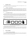
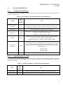
Input for an electret-type microphone similar to Ericsson GE
DWG 19C851086P10, 11. DC bias present (3.5 Vdc for 1000
ohms).
Boom/Gooseneck Microphone Input
"B/G MIC HI"
High impedance input for a dynamic microphone similar to
Shure Bros. Model VR300 (Ericsson GE DWG 19C337100).
Call Director Input
"CD MIC HI"
Unbalanced input designed to accept inputs from a call-director
device similar to Plant Equipment Model 3780-L1-TT-010.
Page Tone Input
"PAGERINPUT HI"
Unbalanced input designed to accept inputs from a tone source.
Line (RJ11) Inputs
LINE A
LINE B
Two balanced 2-wire inputs designed to receive voice bandwidth
and analog audio from a conventional 4-wire, 600-ohm, twistedpair transmission system.
PTT and Sense Inputs
Inputs used for detection of "dry-contact" switch closures of the
type found in common push-to-talk microphones, foot-switches,
and headset jacks.
Digital Inputs
"Generic" digital inputs designed to allow signaling to the computer (via the Logic Board) from external hardware.
OUTPUT SPECIFICATIONS
Line (RJ11) Outputs:
LINE A
LINE B
Two balanced 2-wire outputs designed to transmit voice bandwidth and analog audio to a conventional 4-wire, 600-ohm,
twisted-pair transmission system.
Headset Receiver Outputs
SPECIFICATIONS
OPERATING VOLTAGE
115 or 230 volts AC selectable, 47/63 Hz
TEMPERATURE RANGE
0°F to 75°F
"OPR RCVR HI" and
"SUPR RCVR HI"
Analog audio outputs for two telephone-style headset earphones
similar to Plantronics Model HS0309-1 or equivalent.
Speaker Outputs
Speaker A and Speaker B
DIMENSIONS (H x W x D)
Audio Tower
Remote Volume Controller Box
18" x 6.5" x 15"
2.25" x 12" x 13"
WEIGHT
Audio Tower
Remote Volume Controller Box
27 lbs.
8 lbs.
Select Recorder/Unselect Recorder Output
"SEL RCDR HI" or
"USEL RCDR HI"
Relay Outputs
INPUT SPECIFICATIONS
Audio power amplifier outputs designed to drive compatible
speakers (3.2-16 ohm) to room-filling audio levels.
Unbalanced audio output designed to connect to the audio input
of a recording device.
Outputs consisting of a single pair of "dry" relay contacts isolated from all other signals or ground potential.
Headset Inputs
"SUPR MIC HI"
and "OPR MIC HI"
Copyright© September 1991, Ericsson GE Mobile Communications Inc.
Inputs for two carbon (simulated carbon) telephone-style headset
microphones similar to Plantronics Model HS-0309-1 or equivalent.
DC bias present (3 Vdc for 50 ohms).
1
LBI-38715
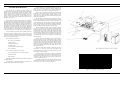
SYSTEM DESCRIPTION
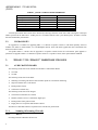
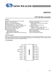
The Ericsson GE C3 Maestro Console System is a
dispatch console system which provides common dispatcher
features on a PC-AT platform. A display on the PC’s video
monitor replaces the conventional array of controls. A cabinet (the Audio Tower) contains the switching system. A
remote Volume Controller Box (VCB) enables the dispatcher to control the output volume levels directed to the
speakers (see Figure 1).
The C3 Maestro enables the dispatcher to use headsets,
microphones, and a variety of external inputs. It supports
600-ohm balanced audio inputs and outputs. The C3 Maestro
allows operation with 2 headsets: an operator headset and a
supervisor headset. The C3 Maestro also allows the use of 2
microphones: a desk microphone and a boom or gooseneck
microphone. Software and jack sense circuitry determine
which of the inputs are active. Push-to-talk (PTT) capability
is provided either in the headset jack, microphone jack,
screw terminal jack, or an internal VOX (for Call Director).
The C3 Maestro also provides for 2 normally open relay
contacts (NO) and 2 digital inputs on each active circuit
board. This results in a total of 6 relay contacts and 6 digital
inputs on a 4 speaker system. Recorder outputs are provided
for use with external recorders.
The C3 Maestro consists of:
–
a PC (with a Logic Board)
–
a video monitor
–
a dispatcher keyboard
–
an Audio Tower
–
a remote Volume Controller Box
–
a set of speakers.
The C3 Maestro Audio Tower contains:
–
up to two PA Boards (in a 4 speaker system)
–
the Matrix Board
–
the I/O Board.
The remote Volume Controller Box contains the Volume
Controller Board.
The following is a detailed description of how the C3
Maestro main components work together.
LBI-38715
The C3 Maestro is a complete dispatching system designed to be connected to Ericsson GE PST Trunking systems. The PC is connected to the Central Electronic
Controller (CEC) by an RS-232 communications line.
The PC has a specialized program which enables the
dispatcher to monitor and control a large number of radio
links. The PC’s video monitor displays graphic representations of the radio links which are currently being controlled by the dispatcher.
Through the use of the keyboard, PC hardware, and PC
software, the dispatcher can issue commands to the Audio
Tower, which interconnects the appropriate signal lines. All
signal interfaces and switching logic are housed in the Audio
Tower. The Audio Tower controls the C3 Maestro audio lines
and the VCB. In most cases, ther Logic Board will make
audio switching decisions without PC intervention.
The PC controls the Audio Tower’s functions through
the 37-pin control cable, which provides a parallel interface.
Switching signals are sent through the control cable only
when an event, such as PTT, occurs. Other than PTT and the
VU meter DC voltage, the control cable is idle most of the
time. In addition, the electronics in the Audio Tower generate
no clock signals and contain on oscillators. Therefore, the
C3 Maestro will not be a source of signals to be received by
other equipment.
When in use, the Central Electronics Controller (CEC)
sends information over the communications link to the PC
about calls that are currently active. The PC updates its video
monitor to reflect the status of active links. The Audio Tower
sends any PTT or jack sense information to the PC. The PC
sends PTT request information to the CEC. The CEC then
routes the incoming audio from the Audio Tower to the
appropriate channel.
When the Audio Tower detects a change in jack sense
information, it selects the appropriate microphone and
speaker/headset input/outputs via the matrix switches, without need for PC intervention.
Normally, audio from the CEC consists of 2 channels:
"Select" and "Unselect". The "Select" audio channel is associated with the dispatchers primary, or selected, group. The
"Unselect" audio channel receives audio from the dispatcher’s unselected groups.
The VCB contains the volume controls for the speakers
connected to the Audio Tower. Normally there are two volume controls: one "Select" and one "Unselect."
15
14
13
12
11
10
9
8
7
6
5
4
3
2
1
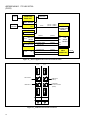
ITEM
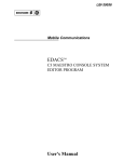
INTERFACE CABLES
FOOTSWITCH
OPERATOR/SUPERVISOR HEADSET JACKS
LOUDSPEAKER
DESK MICROPHONE
GOOSENECK MICROPHONE
PC KEYBOARD
SYSTEM KEYBOARD
VOLUME CONTROL BOX
CRT MONITOR
COMPUTER
AUDIO TOWER UNIT
DESCRIPTION
5050006000
19C337094P4
19A705762G1
3660011000
19B235093G1
7590148000
5050008000
505009000
5050011000
PART NUMBER
Figure 1 - C3 Maestro Console System
2
1
2
2
1
1
1
1
1
1
1
1
QTY.
LBI-38715
LBI-38715
OPERATING PROCEDURES
The following procedures are condensed instructions
intended for use when installing the C3 Maestro. Refer to
the Operator’s Manual for more detailed operating instructions.
CABLING
The following links must be established to install the C3
Maestro properly:
–
PC-to-Audio Tower
–
PC-to-dispatcher keyboard
–
PC-to-CEC
–
Audio Tower-to-VCB
–
Audio Tower-to-Speakers
–
Audio Tower-to-Mic.
–
Audio Tower-to-Footswitch
Internal cables are provided for the PA Board-to"SPREADER BOARD" link.
The following are detailed instructions for cabling the
C3 Maestro. (Refer to the System Interconnection Diagram
and Audio Tower Rear Panel Diagram.)
PERSONAL COMPUTER (PC)
Connect the PC video board to the video monitor using
the video monitor to computer cable.
Connect the PC keyboard to the standard keyboard jack
on the back of the PC. The Logic Board, which has a DB37
jack and a 4-pin jack for the dispatcher keyboard, is installed
as an expansion board in one of the ISA expansion slots in
the PC. Connect the DB cable to the DB37 jack. Plug the
4-pin connector from the dispatcher keyboard into the 4-pin
jack on the Logic Board. Note that the connector is keyed.
The red dot on the 4-pin jack should be aligned with the red
dot on the 4-pin cable plug. The 4-pin cable plug will latch
in place. To remove the 4-pin cable, pull on the sleeve.
Pulling on the 4-pin cable will not free the latch and may
damage the cable if excessive force is used.
Connect the CEC cable to the "COM1" port on the
"mother board" of the PC. Make the appropriate connection
and fasten all connectors in place. Internal wiring of this
DB-25 connector will determine whether RS-232 or RS-422
is used for the link.
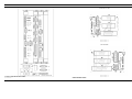
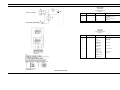
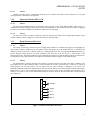
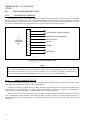
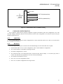
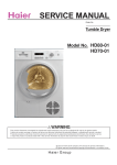
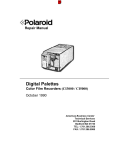
Figure 2 - System I/O Diagram
(This diagram shows the possible audio paths in the system)
AC power cables for both the video monitor and the PC
are provided. Connect the AC power cables to their respec-
tive connectors located on the rear chassis, but do not connect them to the mains power at this point.
AUDIO TOWER
Verify that the circuit boards are installed properly.
From the back of the Audio Tower with the door open, you
can see the boards in the board cage. From left to right, they
are: the I/O Board, the Matrix Board, the PA Board, and a
blank panel. There will be an additional PA Board in place
of the blank panel if the console is configured for 4 speakers.
The backplane connectors are designed to prevent
boards from being inserted into incorrect slots.
Verify that all boards are installed properly and that the
screws holding them in place are completely tightened.
Connect the DB37 cable from the PC to the DB37 jack on
the Matrix Board. Disconnect the removable screw terminals
for the speakers that are located on the PA Board and connect
the speaker wires to the terminals. Reconnect the screw
terminals to the PA Board, route the speaker leads to the
correct location and connect the leads to the appropriate
speaker (Select or Unselect). The upper pair of terminals is
for the "Select" channel and the lower pair of terminals is for
"Unselect". Speakers are normally located with one speaker
on each side of the video monitor for ease of use.
Connect the DB15 cable to the back of the VCB. The
VCB may be located under the video monitor or anywhere
else that is convenient. Route the other end of the DB15
cable as needed and connect it to the DB15 jack labeled
"Volume Controller" on the back of the Audio Tower. Connect the 12" DB9 cable from the DB9 jack labeled "PA
Volume" on the first PA Board (adjacent to the Matrix Board)
to the bottom DB9 jack (labeled "A") on the back of the
Audio Tower. If you have a second PA Board, its "PA Volume" DB9 is cabled to the top DB9 connector (labeled "B")
on the back of the Audio Tower. For the CEC remote audio
input/output connections, use the RJ11 jacks on the PA
Board. The top RJ11 jack (labeled "Line B") is for the
"Unselect" audio (in and out). Consult the wiring diagram in
the Maintenance Section to verify connections within the
RJ11 plug.
To use a Boom, Gooseneck, or other dynamic microphone, connect it to the DB9 jack marked "B/G MIC" on the
Matrix Board. Care must be taken to avoid connecting a
magnetic microphone to the wrong jack otherwise damage
may occur to the microphone.
If you have an electret-type Desktop Microphone, connect it to the jack marked "Desk Mic" on the Matrix Board.
Headset connections for Operator and Supervisor are
also provided on the Matrix Board. Please refer to the wiring
diagram in the Maintenance Section to verify correct connections before attempting to connect these devices.
3
LBI-38715
LBI-38715
To use an adapter box which converts an Audio Tower
DB9 headset connection to a "Bantam" jack box, please
consult vendor information before connecting headsets.
Power up the Audio Tower first to ensure that it is ready
to receive the initialization commands from the PC. Next,
power up the PC.
Footswitches used to enable specific PTT and monitor
functions may be connected at the I/O Board. Consult the
wiring diagram in the Maintenance Section to verify connections before using them.
NOTE: The CCS software must already be loaded onto the
PC for the system to function. Please refer to the Installation
Manual for instructions on loading the C3 Maestro software
onto the PC.
Removable screw terminals are provided for "Select"
and "Unselect" recorder connections.
After a few seconds you should hear a short tone in the
"Select" speaker. The tone signals that the PC software,
Logic Board, Matrix Board, PA Board, and all links are
working. If you do not hear the tone, check the volume
controls and cycle the power to the PC off and on.
Removable screw terminals are also provided for the
"B/G PTT" and "Desk PTT" circuits. You can use these
terminals instead of the DB9 Footswitch jacks if desired,
since the terminals are wired directly to the connections in
the respective DB9 Footswitch jacks.
To use a Paging encoder input, connect it to the removable screw terminals provided. To use a Call Director input/output, consult the wiring diagram in the Maintenance
Section and use the DB9 connector provided on the I/O
Board. (NOTE: Use of a call director may require use of
external transformers "in-line" with the call director I/O. All
matrix board revisions require external "in-line" transformers).
Connect the power cable to the Audio Tower but do not
connect it to line power yet.
CONTROLS
The On/Off switch is the only control device on the
Audio Tower. A LED power indicator on the front panel and
also on the back panel, indicate that the Audio Tower is on.
The PC has a single On/Off switch, as does the video
monitor.
USING THE SYSTEM
altkbd.dat
config.dat
conkey.com
console.exe
editor.exe
entity.dat
font33.dat
shift.dat
CONSOLE PROGRAM
INSTALLATION DATA
SOFTWARE INSTALLATION
The DG Dasher 386SX-20 should be set up with the
following directories and files:
UTIL Directory
Subdirectory
Contents of the UTIL directory should be empty.
C:\Files:
As the software on the PC initializes, a second tone will
be heard and a partitioned screen appears on the video
monitor. If communications cannot be established between
the PC and the CEC, a "COMM ERROR:CIM Link Down"
message is displayed. If this occurs, check the PC to CEC
cable.
Note the large clock display in the lower right corner.
Also note the 2 rows of 7 modules. These modules represent
the entities (groups, units, etc.) that the dispatcher may
program into the console. Consult the USER’S MANUAL
for module programming instructions.
Using the dispatcher keyboard, the dispatcher can "Select" the desired module. The "Select" entity is then highlighted on the video monitor, and any audio received is sent
to the "Select" speaker. Other audio received is sent to the
"Unselect" speaker. Each speaker has its own volume control
on the VCB.
Microphones or Headset/footswitches connected to the
Audio Tower have their audio signals routed to the correct
channel when their respective PTT is activated. When a
channel is granted, the video monitor is updated to reflect
the PTT’s active status.
SPREADER BOARD
autoexec.bat
config.sys
command.com (MS-DOS V3.30)
io.sys (MSW-DOS V3.30 - hidden)
msdos.sys (MS-DOS V3.30 - hidden)
Directories
DOS (MS-DOS V3.30)
CONSOLE
UTIL
Autoexec.bat
Contents of the AUTOEXEC.BAT file are:
path=c:\dos;c:\util
prompt $p$g
cd\console
conkey
console
EPROMS Files
In addition to files located on the DG Dasher 386SX-20
hard drive, a CLB.HEX file is required to program the
EPROM located on the Console Logic Board. This file will be
supplied by Ericsson GE to vendor with each release of CLB
firmware. Vendor will ensure that the newest release CLB
firmware in their possession will be placed on each unit delivered. Furthermore, the CLB firmware release number and
checksum must be properly located on the EPROM labels
supplied by Ericsson GE.
SYSTEM TEST
Listed below are test procedures for a complete C3 Maestro Console system. In case of problems, refer to the same item
number in the "PROBLEM RESOLUTION" section.
Required tools:
Config.sys
Oscilloscope, DVM, Audio signal source,
test leads, Complete PC with Logic Board,
Complete Audio Tower with I/O Board,
Matrix Board, and PA Board installed,
Complete VCB, "CTEST" test software
diskette, Matrix Extender Board, PA Extender Board.
Setup procedure:
With all of the separate components correctly cabled,
connect the power cables to AC power mains.
Set the volume controls on the VCB at midpoint.
4
The Spreader Board is basically a "Y" cable adapter. It
merges the signals from the PA board (s) into a single DB15
cable and connects to the Remote Volume Controller. Additionally it has a power jack to supply 15 Vdc for external
devices and a LED which indicates that the chassis is powered up.
Contents of the CONFIG.SYS file are:
Files=20
Buffers=25
device=c:\dos\ansi.sys
Contents of the CONSOLE directory will be supplied by
Ericsson GE to Vendor with each release of the C3 Maestro
Console software. Vendor will ensure that the newest release
of the C3 Maestro console software, in their possession, will
be placed on each unit delivered. Contents of the console
directory are:
–
Assemble and cable the Audio Tower and PC as described in the "Cabling" section.
–
Cable the VCB to the Audio Tower.
–
Cable the speakers to the removable screw terminals
on the PA Board and install the screw terminals to the
PA Board.
–
Power up the Audio Tower, and then power up the PC.
–
When the PC has finished booting up, insert the
"CTEST" software diskette into the diskette drive and
close the latch.
–
From the PC keyboard type the command:
LBI-38715
LBI-38715
X6770
X7770
X8731
A:CTEST
and press the <Enter> key. A complete screen should
appear which displays the following message at the
top of the screen:
"Console Logic Board detected
–
version x.xx "
You are now ready to test the functionality of the
complete system.
Test procedures:
1.
LINE A to Speaker B
–
–
–
–
–
Using an RJ11 plug and the audio signal source,
input a measured 2.2-volt ( 0.1) peak-to-peak 1
kHz sine wave into pins 2 and 5 of the 6-pin plug.
Insert the plug into the top RJ11 jack on the PA
Board.
Measure and adjust the level of the signal as the
PA Board places a 600-ohm load on its inputs.
Adjust both volume controls on the VCB to the
midpoint.
From the keyboard type the command:
3.
–
–
–
–
X6771
X7771
X8731
4.
Adjust the volume up and down.
When you have determined that both the input
and the speaker work satisfactorily, type the following commands, making sure to press the Enter
key after each command:
The PC with a Logic Board and its ability
to control the switches on the Matrix
Board.
Remove the RJ11 plug from the top RJ11 jack on
the PA Board and insert it into the other RJ11 jack.
Type the command:
X6641
–
–
–
–
–
–
–
Adjust the volume up and down.
When you have determined that both the input
and the speaker work satisfactorily, type the command:
–
–
Type the following commands, making sure to
press the Enter key after each command:
–
–
LINE B To Speaker A
–
–
You should hear a tone in the speaker controlled
by the left-most volume knob.
–
–
3.
X6671
X7771
X8371
and press the Enter key. The tone should stop.
Type the following commands, making sure to
press the Enter key after each command:
The VCB and its cabling
LINE A To Speaker B
and press the Enter key. The tone should stop.
X6740
–
2.
1.
X6640
Adjust the volume up and down.
When you have determined that both the input
and the speaker work satisfactorily, type the command:
LINE A to Speaker A
The amplifiers on the PA Board
Use the following procedures for problem resolution:
and press the Enter key. You should hear a tone
in the speaker controlled by the right-most volume knob.
and press the Enter key. You should hear a tone
in the speaker controlled by the right-most volume control knob.
2.
1.
LINE B To Speaker B
–
X6741
–
–
You have just tested the Line A input and
switched it to both speakers. You have also tested:
PROBLEM RESOLUTION
You should hear a tone in the speaker controlled
by the left-most volume knob. Adjust the volume
up and down.
When you have determined that both the input
and the speaker work satisfactorily, type the following commands, making sure to press the Enter
key after each command:
–
–
X6670
X7770
X8730
The tone should stop.
–
You have just tested the LINE B input and
switched it to both speakers.
This completes the system test.
–
–
Power down the Audio Tower.
Remove the PA Board from the board cage.
Verify that the jumpers on the PA Board are in
the "A" position. If they are not, set them in the
"A" position and return to the regular test procedure to test again.
Insert the PA Extender Board into the PA Board
slot.
Insert the PA Board into the connector on the
edge of the PA Extender Board.
Power up the Audio Tower.
Using the oscilloscope, observe the signal at
BR5, pins 1 and 3. If no signal is present, the
problem is probably with the RJ11 jack or the
plug. If the signal is present, trace it from
beginning to end until the problem is found.
Check for signal at U9, pin 12, 13. If no signal
is found, the problem is in bridge BR1, T1, or
the resistors between them.
Connect the ground lead to ground on the
board. Check for signal at U9, pin 14. Then
check for signal at U9, pin 8. If signal is found
at U9, pin 8, the problem is not on the input side
of the PA Board.
Check for signal at U5, pin 13. If signal is
found, check for signal at U5, pin 12. If no
signal is found, the problem may be with the
VCB Box or the cable to it.
Check for DC voltage at U5, pin 16. If the
voltage is less than 1 volt DC even with the
volume controls at maximum, the problem is
in the VCB or its cables and connectors. If DC
is present, U5 may be defective. If signal is
found, check for signal at U8, pin 12.
Check U8, pin 14. This is the final input to the
amplifier. If signal is found there, either the
amplifiers are defective or the speakers and
their leads are suspect.
If no signal was found at U5, pin 13, power
down the Audio Tower. Remove the PA Board
and the PA Extender Board from the board
cage. Replace the PA Board in its slot. Remove
the Matrix Board and place the Matrix Extender Board in its slot. Insert the Matrix Board
into the connector on the edge of the Matrix
Extender Board.
Power up the Audio Tower.
Connect the Oscilloscope ground lead to any
ground on the Matrix Board. Look for signal at
–
U6, pin 20. This is the input to the matrix. If no
signal is detected, the problem is in the backplane or its sockets. If signal is present, connect
the scope lead to U6, pin 14. There should be
no signal present.
From the PC keyboard type the command:
X6741
and press the Enter key. Signal should now be
present. If no signal is seen, the matrix is not
working or the cable from the PC to the Audio
Tower is defective. In either case, the system
is not functional.
–
2.
Repeat the procedure with a known functional
cable and PC system. If the problem is still
present, the decoder logic or address lines of
the Matrix Board are defective. The problem
may be with the backplane.
LINE A To Speaker A
–
–
–
–
–
–
–
–
–
–
–
–
Power down the Audio Tower.
Remove the PA Board from the board cage.
Verify that the jumpers on the PA Board are in
the "A" position. If they are not, set them in the
"A" position and return to the regular test procedure to test again.
Insert the PA Extender Board into the PA Board
slot.
Insert the PA Board into the connector on the
edge of the PA Extender Board.
Power up the Audio Tower.
Using the oscilloscope, observe the signal at
BR5, pins 1 and 3. If no signal is present, the
problem is probably the RJ11 jack or the plug.
If signal is present, trace it from beginning to
end until the problem is found.
Check for signal at U9, pin 12, 13. If no signal
is found, the problem is in bridge BR1, T1, or
the resistors between them.
Connect the ground lead to ground on the
board. Check for signal at U9, pin 14.
Check for signal at U9, pin 8. If signal is found
at U9, pin 8, the problem is not on the input side
of the PA Board.
Check for signal at U5, pin 4. If signal is found,
check for signal at U5, pin 5. If no signal is
found, the problem may be with the VCB or the
cable to it.
Check for DC voltage at U5, pin 1. If the
voltage is less than 1 volt DC even with the
volume controls at maximum, the problem is
in the VCB or its cables and connectors. If DC
is present, U5 may be defective. If signal is
found, check for signal at U8, pin 3.
5
LBI-38715
–
–
–
–
–
–
–
–
LBI-38715
Check U8, pin 1. This is the final input to the
amplifier. If signal is found there, either the
amplifiers are defective or the speakers and
their leads are suspect.
If no signal was found at U5, pin 4, power down
the Audio Tower.
Remove the PA Board and the PA Extender
Board from the board cage. Replace the PA
Board in its slot.
Remove the Matrix Board and place the Matrix
Extender Board in its slot.
Insert the Matrix Board into the connector on
the edge of the Matrix Extender Board.
Power up the Audio Tower.
Connect the oscilloscope ground lead to any
ground on the Matrix Board. Look for signal at
U6, pin 20. This is the input to the matrix. If no
signal is detected, the problem is in the backplane or its sockets. If signal is present, connect
the scope lead to U6, pin 11. There should be
no signal present.
From the PC keyboard type the command:
X6771
and press the Enter key. Signal should now be
present. If no signal is seen, the matrix is not
working or the cable from the PC to the Audio
Tower is defective. If signal is present, connect
the scope lead to U7, pin 20. There should be
signal present.
–
–
Connect the scope lead to U7, pin 11. There
should be no signal present.
From the PC keyboard type the command:
X7771
lines of the Matrix Board is defective. The
problem may be with the backplane.
3.
–
–
Connect the scope lead to U8, pin 20. There
should be signal present.
Connect the scope lead to U8, pin 15. There
should be no signal present.
From the PC keyboard type the command:
X8731
and press the Enter key. There should be signal
present.
–
6
With or without signal, the system is not functional. Repeat the procedure with a known
functional cable and PC system. If the problem
is still present, the decoder logic or address
–
–
LINE B To Speaker B
–
–
–
–
–
–
–
–
–
–
–
–
and press the Enter key. There should be signal
present.
–
–
–
–
–
–
Power down the Audio Tower.
Remove the PA Board from the board cage.
Verify that the jumpers on the PA Board are in
the "A" position. If they are not, set them in the
"A" position and return to the regular test procedure to test again.
Insert the PA Extender Board into the PA Board
slot.
Insert the PA Board into the connector on the
edge of the PA Extender Board.
Power up the Audio Tower.
Using the oscilloscope, observe the signal at
BR6, pins 1 and 3. If no signal is present, the
problem is probably the RJ11 jack or the plug.
If signal is present, trace it from beginning to
end until the problem is found.
Check for signal at U10, pins 12 and 13. If no
signal is found, the problem is in bridge BR2,
T2, or the resistors between them.
Connect the ground lead to ground on the
board. Check for signal at U10, pin 14.
Check for signal at U10, pin 8. If signal is
found at U10, pin 8, the problem is not on the
input side of the PA Board.
Check for signal at U5, pin 13. If signal is
found, check for signal at U5, pin 12. If no
signal is found, the problem may be with the
VCB or the cable to it.
Check for DC voltage at U5, pin 16. If the
voltage is less than 1 volt DC even with the
volume controls at maximum, the problem is
in the VCB or its cables and connectors. If DC
is present, U5 may be defective. If signal is
found, check for signal at U8, pin 12.
Check U8, pin 14. This is the final input to the
amplifier. If signal is found there, either the
amplifiers are defective or the speakers and
their leads are suspect.
If no signal was found at U5, pin 13, power
down the Audio Tower.
Remove the PA Board and the PA Extender
Board from the board cage. Replace the PA
Board in its slot.
Remove the Matrix Board and place the Matrix
Extender Board in its slot.
–
Insert the Matrix Board into the connector on the
edge of the Matrix Extender Board.
Power up the Audio Tower.
Connect the Oscilloscope ground lead to any
ground on the Matrix Board. Look for signal at
U6, pin 9. This is the input to the matrix. If no
signal is detected, the problem is in the backplane
or its sockets. If signal is present, connect the
scope lead to U6, pin 14. There should be no
signal present.
From the PC keyboard type the command:
–
–
–
–
–
X6641
and press the Enter key. Signal should now be
present. If no signal is seen, the matrix is not
working or the cable from the PC to the Audio
Tower is defective.
–
4.
With or without signal, the system is not functional. Repeat the procedure with a known functional cable and PC system. If the problem is still
present, the decoder logic or address lines of the
Matrix Board are defective. The problem may be
with the backplane.
–
X6671
and press the Enter key. Signal should now be
present. If no signal is seen, the matrix is not
working or the cable from the PC to the Audio
Tower is defective.
–
LINE B To Speaker A
–
–
–
–
–
–
–
–
–
–
–
Power down the Audio Tower.
Remove the PA Board from the board cage.
Verify that the jumpers on the PA Board are in the
"A" position. If they are not, set them in the "A"
position and return to the regular test procedure
to test again.
Insert the PA Extender Board into the PA Board
slot.
Insert the PA Board into the connector on the edge
of the PA Extender Board.
Power up the Audio Tower.
Using the oscilloscope, observe the signal at
BR6, pins 1 and 3. If no signal is present, the
problem is probably the RJ11 jack or the plug. If
signal is present, trace it from beginning to end
until the problem is found.
Check for signal at U10, pins 12 and 13. If no
signal is found, the problem is in bridge BR2, T2,
or the resistors between them.
Connect the ground lead to ground on the board.
Check for signal at U10, pin 14.
Check for signal at U10, pin 8. If signal is found
at U10, pin 8, the problem is not on the PA Board.
Power down the Audio Tower.
Remove the PA Board and the PA Extender Board
from the board cage. Replace the PA Board in its
slot.
Remove the Matrix Board and place the Matrix
Extender Board in its slot.
Insert the Matrix Board into the connector on the
edge of the Matrix Extender Board.
Power up the Audio Tower.
Connect the Oscilloscope ground lead to any
ground on the Matrix Board. Look for signal at
U6, pin 9. This is the input to the matrix. If no
signal is detected, the problem is in the backplane
or its sockets. If signal is present, connect the
scope lead to U6, pin 11. There should be no
signal present.
From the PC keyboard type the command:
–
–
–
With or without signal, the system is not functional. Repeat the procedure with a known functional cable and PC system. If the problem is still
present, the decoder logic or address lines of the
Matrix Board are defective.
If signal is seen, move the scope lead to U7, pin
20. Signal should be present.
Move the scope lead to U7, pin 11. There should
be no signal present.
From the PC keyboard type the command:
X7771
and press the Enter key. There should now be
signal present.
–
–
–
If no signal is seen, U7 may be defective. If signal
is seen move the scope lead to U8, pin 20. There
should be signal present.
Move the scope lead to U8, pin 15. There should
be no signal.
From the PC keyboard type the command:
X8731
and press the Enter key. There should be signal
now.
–
If no signal is seen, U8 may be defective. If signal
is seen, there may be a problem with the backplane.
GLOSSARY OF ACRONYMS
LBI-38715
B/G:
Boom/Gooseneck
CEC:
Central Electronics Controller
DIP:
Dual In-Line Package
DPRAM:
Dual Port Ram
DVM:
Digital Voltmeter
I/O:
Input/Output
PC:
Personal Computer
PCB:
Printed Circuit Board
PTT:
Push-To-Talk
VCB:
Volume Controller Box
VOX:
Voice Operated Switch
NO:
Normally Open
NC:
Normally Closed
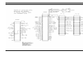
INTERCONNECTION DIAGRAM
LBI-38715
SYSTEM
(P29/9030005000, Rev. 1)
7
LBI-38715
OUTLINE DIAGRAM
OUTLINE DIAGRAM
COMPONENT SIDE
(P29/3700119000, Rev. 1.0)
(P29/3700119000, Rev. 1.0)
SOLDER SIDE
AUDIO TOWER REAR PANEL
(P29/9030007000, Rev. 1)
8
(P29/3700119000, Rev. 1.0)
(P29/3700119000, Rev. 1.0)
SPREADER BOARD
LBI-38715
LBI-38715
SCHEMATIC DIAGRAM
PARTS LIST
LBI-38715
SPREADER BOARD
P29/5000064000
Revised: August 28, 1991
Revision: 1.0
ITEM
QUANTITY
1
2
2
4
5
6
7
2
1
1
1
1
1
1
REFERENCE
J3, J2
J1
J4
J5
R1
R2
LED1
PART
DB9 FEMALE
DB15 FEMALE
WEIDMULLER 12593.6 BL4
AMP 641964-1
PTC KEYSTONE KC0055-ND
820 Ohms
LED
ALL RESISTORS 1/4 WATT 10% CARBON UNLESS NOTED.
BACKPLANE
P29/500058000
Revised: August 26, 1991
Revision: 1.0
ITEM
QUANTITY
1
2
3
4
5
6
7
3
1
2
2
2
1
1
J1, J3, J4
J2
J6, J5
J7, J8
R1, R2820 Ohms
PCS
2 FOOT CABLE,
BACKPLANE TO
POWER SUPPLY
AMP102567-6
AMP1-102692-4
AMP 641964-1
AMP 640456-2
8
1
2 FOOT CABLE,
BACKPLANE TO
FRONT LED
AMP 640440-2
9
10
1
1
POWER SUPPLY
CONDOR GPC80-15
REFERENCE
PART
AMP 350777-1
LED ON FRONT
CABINET
11
1
2 FOOT CABLE TO
SPREADER BOARD
12
1
POWER RECEPTACLE
FUSED
13
1
POWER SWITCH
AMP350777-1 TO
AMP350777-1
ALL RESISTORS 1/4 WATT 10% CARBON UNLESS NOTED.
SPREADER BOARD
9
OUTLINE DIAGRAM
LBI-38715
COMPONENT SIDE
(P29/3700114000, Rev. 1.0)
(P29/3700114000, Rev. 1.0)
BACKPLANE
10
LBI-38715
SOLDER SIDE
(P29/3700114000, Rev. 1.0)
(P29/3700114000, Rev. 1.0)
LBI-38715
SCHEMATIC DIAGRAM
LBI-38715
BACKPLANE
11
LBI-38715
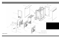
MECHANICAL PARTS BREAKDOWN
LBI-38715
13
12
11
10
9
8
7
6
5
4
3
2
1
ITEM
AUDIO TOWER
(P29/9030002000, Sh. 1, Rev. 1)
12
OVERLAY (GE MOBILE COMMUNICATIONS)
SIDE PANEL
FRONT DOOR ASSEMBLY
LOCK ASSEMBLY
REAR DOOR
FILLER PANEL ASSEMBLY
INPUT/OUTPUT CARD ASSEMBLY
POWER AMPLIFIER CARD ASSEMBY
AUDIO MATRIX CARD ASSEMBLY
HINGE
VERTICAL PANEL
CARD CAGE
FRAME BASE ASSEMBLY
DESCRIPTION
614088000
6090208000
6090209000
6090258000
6090210000
6090282000
5000057000
5000055000
5000056000
6090304000
6090283000
6090224000
PART NUMBER
2
2
1
1
1
1
1
1
1
2
1
1
1
QTY.
LBI-38715
SCHEMATIC DIAGRAM
LBI-38715
CONSOLE SYSTEM CONNECTIONS
13
ADDENDUM NO. 1 TO LBI-38715A
(PCCR)
1.
INTRODUCTION
This addendum provides details about the C3 Maestro Audio Tower hardware revisions designated as “Phase 2”. It also
provides information on the Call Director (CD) telephone patch feature.
1.1.
“PHASE 1” AND “PHASE 2”
The Phase 2 Audio Tower replaces the original Audio Tower which will be referred to as “Phase 1” in this document. All
boards in the tower, the Audio Matrix Board, the Audio PA Board, the I/O Board and the Backplane, have been revised to
support the Call Director telephone patch feature. Performance and reliability has also been improved. Except for minor
changes noted in this document, the Phase 2 boards are designed to be backward compatible with Phase 1 boards. A revised
maintenance manual documenting the Phase 2 hardware will be issued at a later date. Contact your service representative for
additional information.
1.2.
CALL DIRECTOR PATCH
The CD patch feature allows the Call Director to be "patched" to specific units, talk groups, conventional channels and
radio patches in the CEC/IMC. The term patch or patched is used to convey the CD is connected to the CEC/IMC. This is
derived from phone patch. The term radio patch shall be used to mean a collection of interconnected radio talk groups.
The CD-to-radio patch operates independently of the normal operator-to-radio communications. Using the CD interface,
the operator is only required to connect the CD with the target entity. After that, no other operator intervention is required
until the CD-to-radio connection must be disconnected.
The audio connections between the CD and the CEC/IMC are done inside the C3 Maestro Audio Tower as controlled by
the Logic Board within the computer. The console application program has minimal involvement in the control of audio
switching.
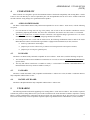
CALL
DIRECTOR
MAESTRO
AND
AUDIO
TOWER
CEC/IMC
Figure 1 − Basic Call Director Audio Routing
The terms incoming, outgoing, inbound, and outbound shall be referenced from the console. Unless otherwise noted, all
audio and signal descriptions are referenced from the Audio Tower.
Message-trunked calls are used to perform the patch operation. The console uses a secondary LID for the patch channel
requests, thus allowing CD patch operation to work separately from, and concurrently with, the normal operator-to-radio
communication. From the standpoint of the radio user, the patch will appear to operate the same as a telephone interconnect
call.
2.
2.1.
PART NUMBERS
TOWER AND BOARD ASSEMBLIES
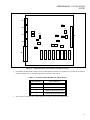
Part numbers for the new (Phase 2) Audio Tower and board assemblies are shown in Table 1. With the exception of the
Audio PA Board, the Call Director patch feature requires all Phase 2 boards. Phase 1 Audio PA Boards (P29/500005500, any
revision) may be used in an Audio Tower that supports CD patch.
1
ADDENDUM NO. 1 TO LBI-38715A
(PCCR)
TABLE 1 − PHASE 2 AUDIO TOWER ASSEMBLIES
ASSEMBLY
2-Speaker Audio Tower
4-Speaker Audio Tower
Audio PA Board
Backplane Board
Audio Matrix Board
I/O Board
*
PART NUMBER
P29/7720033000
P29/7720033001
P29/7720028000
P29/7720029000
P29/7720030000
P29/7720031000
REVISION
n/a
n/a
A* (or later)
A* (or later)
A* (or later)
A* (or later)
Initial Revision
A board’s part number and revision can be checked by removing it from the Audio Tower and verifying the vendor part
number specified in the table above. Vendor parts are not marked with the “P29/” part number prefix. All Phase 1 boards
have P29/50000xx00x part numbers.
2.2.
UPGRADE KITS
An upgrade kit is available for upgrading Phase 1 C3 Maestro 4-speaker consoles to CD Patch capability. Each kit
includes new (Phase 2) Audio Matrix, I/O, and Backplane Boards. Order CD Patch Upgrade Kit P29/7720034000 from
Ericsson GE Service Parts.
Two-speaker Phase 1 consoles must be upgraded to 4-speaker consoles before the Call Director patch upgrade is
performed. To upgrade a Phase 1 C3 Maestro 2-speaker console to a 4-speaker console, order option number CRFK1B.
3.
“PHASE 1”-TO-“PHASE 2” HARDWARE CHANGES
3.1.
AUDIO MATRIX BOARD
The following circuits have been eliminated in the Phase 2 Audio Matrix Board:
•
•
CD VOX
CD PTT
The following circuits have been added:
•
•
•
•
Summing of incoming call director audio with line inputs for conversation monitoring
Supervisor headset mic to call director
Boom/gooseneck sense
Call director on-hook relay
The following circuits have been changed:
•
•
•
•
CD interface transformers are isolated
Headset sidetone levels are controlled by digital pots
Boom/gooseneck mic gain increased
Paging tone level to speakers and headsets reduced
The Phase 2 Audio Matrix Board is required for the Call Director patch feature.
3.1.1.
3.1.1.1.
Summing Of Incoming CD Audio
Phase 1
Incoming CD audio summation did not exist.
2
ADDENDUM NO. 1 TO LBI-38715A
(PCCR)
3.1.1.2.
Phase 2
Incoming CD audio may be summed with incoming select or unselect radio audio so that both sides of a CD patch
conversation can be monitored by the dispatcher.
3.1.2.
3.1.2.1.
Supervisor Headset Mic To CD
Phase 1
The supervisor headphone could not be connected to the CD input via the Audio Matrix Board’s audio switches. A
modification was made by adding a resistor that connected the headphone to the CD when the operator headset was plugged
in. However, the supervisor headset mic could not be connected to the CD output.
3.1.2.2.
Phase 2
The supervisor headset is properly connected to both the CD input and output via the Audio Matrix Board’s audio
switches when the headset is plugged in. It is not affected by the operator headset.
3.1.3.
3.1.3.1.
Boom/Gooseneck Mic Sense
Phase 1
The sensing of a boom or gooseneck mic was not supported by hardware. If a headset was plugged in or unplugged, the
Logic Board’s firmware would switch the microphone between the headset mic or the default desk mic. A software-based
method was utilized, where the C3 Maestro would set a "boom/gooseneck mic bit" in a Logic Board DPRAM options byte,
and the firmware would check the bit before switching to the desk mic. If the bit was set, it would switch to the
boom/gooseneck mic. The Maestro read the bit from CONFIG.DAT, which was set with the Editor program (see LBI-39056).
It was desirable to have direct hardware sense support and eliminate the indirect support via the Editor program.
3.1.3.2.
Phase 2
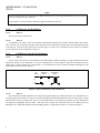
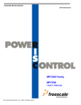
The unused Phase 1 CD PTT input has been changed to a boom/gooseneck sense input in the Phase 2 hardware. The
Logic Board now has a direct hardware input to read to determine if a boom or gooseneck mic is connected. A connected
boom/gooseneck mic will take priority over the default desk mic when a headset is unplugged or not sensed. The
EDITOR/CONFIG.DAT/option bit method has been removed from the Maestro V3.0 Editor program. Existing Audio Matrix
Boards, Rev 2.0 - Rev G, may be modified to duplicate the sense circuit so they will be compatible with Logic Board V3.0
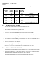
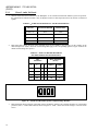
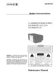
firmware. See section 4.1 for specific modification instructions. Figure 2 shows the pin-out of the Phase 2 boom/gooseneck
mic connector J4.
1
2
Ground
4
3
Sense
6
PTT
5
Mic Lo
9
Mic Hi
J4
Figure 2 - Boom/Gooseneck Mic Connector J4
3
ADDENDUM NO. 1 TO LBI-38715A
(PCCR)
NOTE
All boom and gooseneck mic connectors (male DB-9) must have pins 2 and 3 jumpered together so the sense circuit
will be active when the mic is connected.
Logic Board V3.0 firmware must be installed to support the hardware sense line.
3.1.4.
3.1.4.1.
Call Director On-Hook Relay
Phase 1
The CD on-hook relay did not exist.
3.1.4.2.
Phase 2
A momentary relay contact closure is provided for automatically placing the CD on-hook without operator intervention.
This "on-hook" relay is energized when the console disconnects the CD from the CEC/IMC due to operator manual operation
or site time-out. Since most CDs do not have an on-hook input, use of this relay is optional. The relay contacts are available
at CD connector J3 on the I/O Board (see Figure 6).
3.1.5.
3.1.5.1.
Call Director Interface Transformers
Phase 1
One leg of the external side of each transformer was inadvertently grounded, resulting in a single-ended interface which
defeated the purpose of the transformers. An in-line “transformer box” was provided to isolate the call director from the
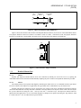
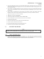
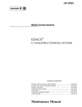
Audio Tower’s circuit grounds. The external Phase 1 CD connections from the I/O Board, through the Backplane to the
Audio Matrix Board are shown in Figure 3.
I/O
Board
Backplane
Board
Audio Matrix
Board
J3
Figure 3 - Phase 1 CD Interface (Mic and Receive)
3.1.5.2.
Phase 2
The external sides of both transformers are isolated from ground, resulting in a balanced interface. The transformer box is
no longer required if the Phase 2 revisions of both the Audio Matrix Board and I/O Board are used. If only a Phase 2 Audio
Matrix Board is used, two jumpers (JP1, JP2), one for each transformer, are provided to ground one leg of the transformers
for backwards compatibility with the Phase 1 I/O Board. The external CD connections from the I/O Board across the
Backplane to the Audio Matrix Board, and the grounding jumpers, as implemented in Phase 2, are shown in Figure 4.
4
ADDENDUM NO. 1 TO LBI-38715A
(PCCR)
I/O
Board
Backplane
Board
Audio Matrix
Board
J3
JPx
Figure 4 − Phase 2 CD Interface (Mic and Receive)
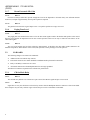
Figure 5 shows the locations of JP1 and JP2 near Backplane Board connector (J6) at the rear of the Audio Matrix Board.
The jumpers should be removed if a Phase 2 I/O Board is used. If a Phase 1 I/O Board is used, the jumpers should be
inserted. If a call director is not attached to the Audio Tower, the placement of the jumpers is insignificant.
JP1
J6
Transformer
JP2
Figure 5 − CD Transformer Jumper Locations
3.1.6.
3.1.6.1.
Headset Sidetone Pots
Phase 1
Operator and supervisor headset sidetone levels were controlled by manual pots. The levels were set by placing the
Audio Matrix Board on an extender board and manually adjusting the pots. No other level adjustment method was provided.
3.1.6.2.
Phase 2
The manual pots have been replaced with digitally-controlled pots which can be set via commands from the Logic Board.
From new software in the Maestro V3.0 application, the Logic Board can be commanded to vary the sidetone level.
Operator and supervisor sidetone levels are stored in the user profile of each setup. The Maestro application reads the
values from SETUPS.DAT at startup and sends commands to the Logic Board to set the pots to those values. The user adjusts
the operator sidetone level using the <Alt>+ <Vol Up> and <Alt>+ <Vol Down> keys. The supervisor sidetone cannot be
adjusted from the application. It is set via the Editor program by editing the user profile and setting the “Sup Sidetone” field
to a value between 0 - 255. See LBI-39056 for specific details.
5
ADDENDUM NO. 1 TO LBI-38715A
(PCCR)
3.1.7.
3.1.7.1.
Boom/Gooseneck Mic Gain
Phase 1
Gain was not always sufficient to provide enough mic level for the dispatcher to be heard clearly. For sufficient transmit
audio level, an input of approximately 20 mV peak-to-peak was required.
3.1.7.2.
Phase 2
The gain has been increased. Typical input is now 7 mV peak-to-peak at an average voice level.
3.1.8.
3.1.8.1.
Paging Tone Level
Phase 1
The paging tone was summed at the same level as all other audio signals routed to the headset and speakers. This caused
the tones to be heard at an unpleasant level for most console operators. There was no way to reduce the tone relative to the
other audio signals.
3.1.8.2.
Phase 2
The level of the paging tone has been reduced by approximately 16 dB below the other audio signals summed to the
headsets and speakers. This reduction value is fixed, but it provides a more pleasing level to the operator.
3.2.
I/O BOARD
The following changes were made to the I/O Board:
•
•
•
•
Addition of the CD on-hook relay contacts
Footswitch connectors now match standard C3 Modular/Desktop footswitch connections
Relay-1 and Relay-2 connectors are correct
All unused connections to the Backplane Board are no longer grounded
The Phase 2 I/O Board is required for the Call Director patch feature.
3.2.1.
3.2.1.1.
CD On-Hook Relay
Phase 1
The on-hook relay did not exist. Connector J3 pin 6 carried the CD PTT signal and pin 1 was not used.
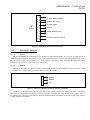
3.2.1.2.
Phase 2
Signal lines to carry the call director on-hook relay contacts from the Backplane Board to connector J3 have been added.
Pin 1 and pin 6 carry the relay contacts. Figure 6 shows the pin-out of J3 on the Phase 2 I/O Board.
6
ADDENDUM NO. 1 TO LBI-38715A
(PCCR)
1
On-Hook Relay Contacts
6
To
Call
Director
2
Handset Jack Sense
3
Off-Hook Sense
4
Ground
5
CD Mic (balanced line)
9
7
CD Receiver (balanced line)
8
J3
Figure 6 - I/O Board Call Director Connector J3
3.2.2.
3.2.2.1.
Footswitch Connectors
Phase 1
The PTT and MONITOR connections for FOOTSWITCH-1 and FOOTSWITCH-2 were reversed. A single footswitch
would activate the MONITOR signal when pressed. Single footswitches had to be rewired so the corresponding Audio Tower
PTT pin was used. Many dual footswitches were wired with their connections reversed. Therefore, these dual footswitches
worked correctly with the reversed Audio Tower connections.
3.2.2.2.
Phase 2
The new I/O Board has pin 6 as PTT and pin 4 as MONITOR on both footswitch connectors as shown in Figure 7. This
is consistent with C3 Modular/Desktop consoles which are used as the standard.
2
Ground
4
Monitor
6
PTT
Figure 7 − Phase 2 I/O Board Footswitch Connectors J5 And J6
If a Phase 2 I/O Board is inserted into the Audio Tower, users with footswitches that operate with Phase 1 I/O Boards
must rewire the footswitch DB-9 connectors to conform to the Phase 2 pin-outs. This can be done by reversing pins 4 and 6 in
the connector or by placing an in-line adapter between the I/O Board and the footswitch to reverse the signals. Figure 8 shows
a simple schematic of an adapter.
7
ADDENDUM NO. 1 TO LBI-38715A
(PCCR)
2
2
4
4
6
6
Female DB-9
Male DB-9
Figure 8 − Footswitch Adapter
3.2.3.
3.2.3.1.
Relay Connections
Phase 1
The contacts for Relay-1 were actually available at the connector (J8 or ST5) labeled “RELAY 2” and the contacts for
Relay-2 were never available.
3.2.3.2.
Phase 2
With a Phase 2 I/O Board, both sets of relay contacts are available at connector J8. Relay-1 is the relay that follows
console PTTs. Relay-2 is reserved for future use. The pin-out of the connector did not change.
3.3.
PA BOARD
The following changes were made to the Audio PA Board:
•
•
3.3.1.
A maximum audio output selection DIP switch was added.
Audio source jumpers JP1 and JP2 were replaced with DIP switches.
Audio Output Switches
These switches (SW1) are new to Phase 2, and provide a method to limit the maximum audio output from each speaker
power amplifier. Levels of 5 watts (recommended) or 8 watts are available. See Table 6 and Figure 10 for details. The
switches have no effect on headset outputs.
3.3.2.
Audio Source Switches
These switches (SW2) and their Phase 1 jumper counterparts are provided for testing. The audio source for each speaker
power amplifier can be selected to be either the corresponding Line Input or the Audio Matrix Board. The Audio Matrix
Board source is the normal selection, but the Line Input selection can be used to test the entire Audio PA Board by bypassing
the Audio Matrix Board. The Line Input is fed directly into the power amplifier. See Table 7 and Figure 11 for details.
3.4.
BACKPLANE BOARD
The following changes were made to the Backplane Board:
•
•
•
Signal lines to carry the call director on-hook relay contacts were added.
The previously grounded legs of both CD interface transformers were added as isolated signals.
Criss-crossed Line B Out and Line D Out signals were fixed. These signals were not used in Phase 1 Audio Towers.
The Phase 2 Backplane is required for the Call Director patch feature.
8
ADDENDUM NO. 1 TO LBI-38715A
(PCCR)
4.
COMPATIBILITY
Phase 2 boards were designed to provide the maximum amount of backwards compatibility with existing Phase 1 Audio
Towers in the event that they are used as replacement parts. The incompatibilities that do exist can be worked around with
external connector wiring changes or Logic Board firmware updates.
4.1.
AUDIO MATRIX BOARD
The Phase 2 Audio Matrix Board is fully backwards compatible for use in a Phase 1 Audio Tower, with the following
exceptions:
1.
If a Call Director is being used, one leg of the primary side of each of the CD interface transformers must be
grounded by jumpering JP1 and JP2. Also, the in-line “transformer” box must be used. See section 3.1.5 for details.
2.
The supervisor headset mic to unselect recorder connection is not supported using Logic Board V2.11 or earlier
firmware. This connection is supported by using Logic Board V3.0 firmware.
3.
If a boom/gooseneck mic is used with the Audio Tower, the following modifications must be made if the Audio
Matrix Board is a Phase 1 board and the Logic Board is equipped with 344A4245G10 (or later) firmware:
•
•
•
4.2.
remove Q1 (disconnects VOX output)
jumper P8 pin 3 to the collector of Q1 (connects new boom/gooseneck sense input to CD PTT)
jumper P8 pin 1 to P8 pin 2 (grounds pin 2)
I/O BOARD
The Phase 2 I/O Board is fully backwards compatible for use in a Phase 1 Audio Tower, with the following exceptions:
The footswitch connector PTT and Monitor connections are reversed. See section 3.2.2 Footswitch Connectors for
specific details.
2.
The relay that follows console PTT is available as “Relay 1” on the Phase 2 I/O Board. Unmodified Phase 1 I/O
Boards had these PTT relay contacts available as “Relay 2”.
4.3.
1.
PA BOARD
The Phase 2 Audio PA Board is fully compatible with the Phase 1 Audio Tower. Also, the Phase 1 Audio PA Board is
fully compatible with the Phase 2 Tower.
4.4.
BACKPLANE BOARD
The Phase 2 Backplane Board is fully compatible with the Phase 1 Audio Tower.
5.
UPGRADING
The following instructions detail the upgrading of an existing Phase 1 Audio Tower to Phase 2. This would be required if
Call Director patch was being added to the system. Table 2 summarizes the items that must be added or replaced in existing
Phase 1 console configurations to implement Call Director patch. The Logic Board in the PC does not have to be changed;
however the firmware may need to be updated. CD patch requires Logic Board firmware 344A4245G10 (or later) firmware.
9
ADDENDUM NO. 1 TO LBI-38715A
(PCCR)
TABLE 2 − HARDWARE ADDITIONS AND REPLACEMENTS REQUIRED
FOR CALL DIRECTOR PATCH
EXISTING (Phase 1) CONSOLE CONFIGURATION
2 Speakers
with CD
2 Speakers
without CD
4 Speakers
with CD
4 Speakers
without CD
Add
5.1.
Replace
Add
Call Director
Replace
Phase 1 Audio Matrix Board, I/O Board
and Backplane Board with Phase 2 Rev. A
(or later) boards
Replace
Replace
Add
Add
Add
Add
Add
Add
Line D In to CIM TX4 (CIM out) wiring (if
not already present)
Add
Add
Add
Add
Line D Out to CIM RX4 (CIM in) wiring
a second Audio PA Board
(Phase 1 or Phase 2)
EXTRACTING PHASE 1 BOARDS
1.
Turn off the power switches on the PC and the Audio Tower and disconnect power.
2.
Unlock and open the Audio Tower rear access door.
3.
Wear an anti-static strap from this point in the procedure forward.
4.
Remove all cables connected to boards in the Audio Tower.
5.
Loosen screws on the I/O Board and pull the board from the Audio Tower by the ejector handles.
6.
Loosen screws on the Audio Matrix Board and pull the board from the Audio Tower by the ejector handles. Place
the Audio Matrix Board in an anti-static bag.
7.
Loosen screws on the Audio PA Board and pull the board from the Audio Tower by the ejector handles. Place the
Audio PA Board in an anti-static bag.
8.
If the system has a second Audio PA Board, pull the board from the Audio Tower by the ejector handles. Place the
second Audio PA Board in an anti-static bag. Otherwise, loosen screws on the Filler Panel and remove it from the
Audio Tower.
9.
Remove the front snap-on cover of the Audio Tower.
10. Disconnect the LED plug from J7 on the Backplane.
11. Disconnect the power plugs from J5 and J6 on the Backplane.
12. Remove the six (6) screws from the Backplane and remove the Backplane from the Audio Tower.
5.2.
10
INSTALLATION OF PHASE 2 BOARDS
1.
Attach the Phase 2 Backplane to the card-cage with six (6) screws. Leave the screws just loose enough to slightly
slide the Backplane.
2.
Insert an Audio PA Board into the far right card slot. Seat the edge connector firmly in the Backplane connector.
Minor lateral positioning of the Backplane may be necessary to make this connection.
3.
Insert a second Audio PA Board adjacent to the first board. Seat the edge connector firmly in the Backplane
connector. Minor lateral positioning of the Backplane may be necessary to make this connection.
ADDENDUM NO. 1 TO LBI-38715A
(PCCR)
4.
Remove the shorting plug from JP1 on the Audio Matrix Board and place shorting plug back on one of the header
pins for storage. Remove the shorting plug from JP2 on the Audio Matrix Board and place shorting plug back on one
of the header pins storage.
5.
Insert the Phase 2 Audio Matrix Board into the correct position in the card-cage. Seat the Audio Matrix Board edge
connector firmly in the Backplane connector. Minor lateral positioning of the Backplane may be necessary to make
this connection.
6.
Insert the Phase 2 I/O Board into the correct position in the card-cage. Seat the edge connector firmly in the
Backplane connector. Minor lateral positioning of the Backplane may be necessary to make this connection.
7.
Tighten the front panel screws on all four (4) boards.
8.
Tighten the six (6) screws on the Backplane.
9.
Attach the power plugs to the Backplane connectors J5BP and J6BP.
10. Attach the LED plugs to connector J7BP located at the bottom of the Backplane.
11. Attach the front snap-on panel.
12. Attach the external cables to the I/O, Audio PA and Audio Matrix Board.
13. Close the rear door of the Audio Tower and lock it.
14. Re-connect and switch on power to the PC and the Audio Tower.
15. After PC has booted, run the Maestro software application.
5.3.
ALIGNMENT PROCEDURES
NOTE
The Phase 2 Matrix and PA boards have been aligned at the factory for typical operating conditions. Further
adjustment is not recommended unless a non-typical signal level is present in the field situation.
5.3.1.
1.
Phase 2 Audio Matrix Board
With the Audio Matrix Board connected to the Backplane via an Audio Matrix Board extender board, and the
Maestro system in operation, the potentiometers indicated in Table 3 may be adjusted to achieve desired operating
levels for the corresponding signals. Figure 9 indicates the positions of the potentiometers.
11
ADDENDUM NO. 1 TO LBI-38715A
(PCCR)
TABLE 3- AUDIO MATRIX BOARD
SIGNAL
POTENTIOMETER
TEST POINT
BOOM/GOOSENECK MIC GAIN
R86
TP19
DESK MIC GAIN
R88
TP20
OPERATOR HEADSET MIC GAIN
R59
TP18
OPERATOR SIDETONE LEVEL
R194
TP31
SUPERVISOR-TO-OPERATOR SIDETONE LEVEL
R90
n/a
SUPERVISOR MIC GAIN
R55
TP33
SUPERVISOR SIDETONE LEVEL
R178
TP32
OPERATOR-TO-SUPERVISOR SIDETONE LEVEL
R213
n/a
CALL DIRECTOR INPUT
R182
TP39, TP40
CALL DIRECTOR OUTPUT
R204
TP43, TP46
SELECT RECORDER OUTPUT
R202
TP44
UNSELECT RECORDER OUTPUT
R187
TP45
PAGING ENCODER INPUT
R199
TP41
VU_METER *
R219
TP48
* Adjustment not recommended
12
ADDENDUM NO. 1 TO LBI-38715A
(PCCR)
J1
R182
J2
R199
R55
J3
SW1
R59
R204
R187
J6
R202
R86
R219
J4
R88
R178 R194
R213
R90
J5
U1
U2
U3
U4
U5
U6
U7
U8
Figure 9 − Audio Matrix Board Potentiometer And SW1 Locations
2.
Switch SW1 (unmarked DIP switch) is used to enable/disable automatic level control (ALC) for the inputs indicated
in Table 4. Enable ALC by setting the appropriate switch to its ON position.
TABLE 4 − AUDIO MATRIX BOARD ALC SWITCH SW1
3.
SW1 POSITION
INPUT SIGNAL
1
B/G MIC
2
DESK MIC
3
OPERATOR HEADSET MIC
4
SUPERVISOR HEADSET MIC
Turn off power and remove the extender board to restore the system to the standard setup.
13
ADDENDUM NO. 1 TO LBI-38715A
(PCCR)
5.3.2.
1.
Phase 2 Audio PA Board
With the Audio PA Board connected to the Backplane via an extender board and the Maestro system in operation,
the potentiometers indicated in Table 5 may be adjusted to achieve desired operation levels for the line A and line B
signals.
TABLE 5 − AUDIO PA BOARD LINE A AND B ADJUSTMENTS
2.
SIGNAL
POTENTIOMETER
TEST POINT.
LINE A IN
R56
TP16
LINE B IN
R58
TP17
LINE A OUT
R95
TP3, TP7
LINE B OUT
R97
TP5,TP9
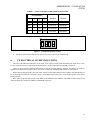
DIP switch SW1 allows selection of the maximum power level available to the speakers. Set the switches to the
desired output level. Table 6 shows the switch settings that apply to the corresponding speakers. Figure 10 shows the
default switch settings (low power).
TABLE 6 − AUDIO PA BOARD MAXIMUM
SPEAKER POWER LEVEL SELECTION
SW1
POSITION
MAX. OUTPUT
(Watts)
1
2
3
4
SPKR 1
SPKR 2
OFF
OFF
x
x
5W
5W
ON
OFF
x
x
8W
5W
OFF
ON
x
x
5W
8W
ON
ON
x
x
8W
8W
"x" = either position
ON
1
2
3
4
Figure 10 − Switch SW1 Maximum Speaker Output Settings (Default)
3.
14
DIP switch SW2 allows selection of the audio sources feeding the speakers. The switches should be set to the default
positions (source = Audio Matrix Board) shown in Figure 11. Table 7 shows the switch settings to select the audio
source.
ADDENDUM NO. 1 TO LBI-38715A
(PCCR)
TABLE 7 − AUDIO PA BOARD AUDIO SOURCE SELECTION
SW2 POSITION
SOURCE
OUTPUT
x
MATRIX BD.
SPEAKER 1
x
x
LINE A IN
SPEAKER 1
x
ON
OFF
MATRIX BD.
SPEAKER 2
x
OFF
ON
LINE B IN
SPEAKER 2
1
2
3
4
ON
OFF
x
OFF
ON
x
x
"x" = either position
ON
1
2
3
4
Figure 11 − SW2 Default Selection Settings
4.
6.
Turn power off and remove the extender board to restore the system to the standard setup.
CD ELECTRICAL INTERCONNECTIONS
The CD-to-CEC/IMC interconnections via the Audio Tower require a second Audio PA Board in the Audio Tower. Also,
a 4-wire CD audio line between this Audio PA Board and the console’s CIM within the CEC/IMC is required.
Figure 12 shows the basic equipment interconnection with all CD patch hardware installed. The number of conductors
required for the patch-related cables is shown. See section 6.2 SIGNAL INTERCONNECTIONS for wiring details.
Both Audio PA Boards will have the same LINE A IN/OUT and LINE B IN/OUT labels. LINE A and LINE B labels on
the second Audio PA Board are considered as LINE C and LINE D respectively. Figure 13 shows the locations of the various
LINE connectors.
Both Audio PA Boards will have the same SPKR A and SPKR B labels. SPKR A and SPKR B labels on the second
Audio PA Board are considered as SPKR C and SPKR D respectively.
15
ADDENDUM NO. 1 TO LBI-38715A
(PCCR)
DISPLAY
CUSTOM
KEYBOARD
COMPUTER
BASE UNIT
LOGIC BOARD
PC
KEYBOARD
CEC/IMC
DATA
COM1
(RS-232 = 3 WIRES)
(RS-422 = 4 WIRES)
AUDIO TOWER
CIM
CONTROLLER
BOARD
MATRIX
LINE A IN
PA-1
LINE A OUT
LINE B IN
PA-2
I/O
LINE B IN
LINE B OUT
{
CD
SELECT
MIC
(2 WIRES)
(2 WIRES)
TX1
RX1
UNSELECT
(2 WIRES)
TX2
PATCHED RADIO
(2 WIRES)
TX4
CD/DISP MIC
(2 WIRES)
RX4
CD RECEIVER
(2 WIRES)
CD MIC
CONTROL
(2 WIRES)
(5 WIRES)
CALL
DIRECTOR
Figure 12 − Basic Equipment Interconnection with CD Patch
PA #1
PA #2
RELAY 2
RELAY 2
LINE A
LINE A
SELECT/MIC
UNSELECT-2
(LINE C)
LINE B
LINE B
CIM CHAN. 4
CD PATCH AUDIO
(LINE D)
UNSELECT-1
DIG. IN 1
DIG. IN 1
DIG. IN 2
DIG. IN 2
Figure 13 − Audio PA Board LINE Connectors
16
CIM
AUDIO
BOARD
PHONE
LINES
ADDENDUM NO. 1 TO LBI-38715A
(PCCR)
6.1.
SIGNAL DESCRIPTIONS
6.1.1.
I/O Board-To-Call Director
Table 8 describes the various signals between the Audio Tower’s I/O Board and the Call Director. The descriptions are
relative to the Audio Tower.
TABLE 8 − I/O BOARD-TO-CALL DIRECTOR SIGNAL DESCRIPTIONS
TYPE
INPUT
OR
OUTPUT
USE
Handset Jack Sense
(optional)
Input
Active low when a handset is plugged into the CD. This handset overrides all audio
connections to the Audio Tower. The operator talks directly to the phone via the
handset instead of using the console’s headset or mic/speaker. Dry contact.
Off-Hook Sense
Input
Active low when the CD is placed off-hook. Dry contact.
Output
Radio/operator mic audio to the CD (telephone receiver). This audio is heard by
the telephone. 600-ohm balanced output:
CD Receiver
-45 dBm to -20 dBm, typically -25 dBm.
CD Mic
Input
Audio from the CD (telephone mic). This audio is heard by a radio in patch
operation, or by operator headset in normal operation.
600-ohm balanced input: -37 dBm to +8 dBm, typically -25 dBm.
On-Hook Relay
(optional)
Output
Normally open dry contact. Closure generated when the console disconnects the
CD from the CEC/IMC. Used to put CD on-hook, if an input exists. The relay
contact is normally-open and remains energized for approximately 1.2 seconds.
This value is fixed in the Logic Board firmware and cannot be changed. Relay
contact ratings are:
0.6 A @ 125 Vac
0.6 A @ 110 Vdc
2.0 A @ 30 Vdc
Ground
6.1.2.
Input
Signal ground for dry contact sense lines.
Audio PA Board #2-To-CIM
Table 9 describes the audio signals between the Audio Tower’s Audio PA Board #2 and the CIM within the CEC/IMC.
The descriptions are relative to the Audio Tower. These signals are interfaced via 600-ohm balanced lines and they have
typical levels of 0 dBm.
TABLE 9 − AUDIO PA BOARD #2-TO-CIM SIGNAL DESCRIPTIONS
TYPE
INPUT
OR
OUTPUT
USE
Patched Radio
Input
Radio audio from CIM TX channel 4. This audio is heard by the telephone.
CD/Operator Mic
Output
Telephone/operator mic audio to CIM RX channel 4. This audio is heard by a radio.
17
ADDENDUM NO. 1 TO LBI-38715A
(PCCR)
6.2.
SIGNAL INTERCONNECTIONS
6.2.1.
I/O Board-To-Call Director
All Audio Tower-to-CD wiring should be included in a single cable that terminates at the Audio Tower in a male DB-9
connector. Since the connections at the CD vary according to manufacturer and model, no specific pin-outs are provided in
the drawing below. The signal names at the CD will not necessarily be the same as those used in this document. It is left to
the end user to determine the proper connections at the CD, based on the previous descriptions given.
To
I/O Board
Call Director
(J3)
1
6
2
3
4
5
9
7
8
On-Hook Relay Contacts (optional)
Handset Jack Sense (optional)
Off-Hook Sense
Ground
CD Mike
CD Receiver
DB-9 Male
Figure 14 − CD-To-I/O Board DB-9 Wiring
NOTE
Some existing call director installations have an in-line "transformer box" installed between the CD and J3. The box
may be removed and the DB-9 from the CD going into the box's cable can be plugged directly into J3. Audio Matrix
Board jumpers JP1 and JP2 must be removed if the transformer box is removed. One jumper is located just above
each of the two transformers near the Backplane connector. See section 3.1.5 for additional details.
6.2.2.
Audio PA Board #2-To-CIM
On the second Audio PA Board (#2), the LINE A IN/OUT connections physically become LINE C IN/OUT and the
LINE B IN/OUT connections physically become LINE D IN/OUT.
Since the CEC/IMC is using RX4/TX4 for CD audio, the console uses the Audio Tower’s LINE D IN and LINE D OUT
connections to keep CD connections to a "fourth" channel on all hardware. This allows the console to use CIM RX3 for
Unselect Speaker 2, connected to LINE C IN (labeled LINE A IN) on Audio PA Board #2.
Install two (2) pairs of audio cables between the CEC/IMC CIM Audio Board and Audio PA Board #2 in the Audio
Tower. Terminate the Audio PA Board’s connection with an RJ-11 connector. The RJ-11 pin-outs are shown in Figure 15.
Due to the distances involved, shielded cable is recommended for these interconnections between the Audio Tower and the
CEC/IMC.
18
ADDENDUM NO. 1 TO LBI-38715A
(PCCR)
To
P.A. Board #2
Line B
("Line D")
1
2
5
3
4
6
NOT USED
CIM TX 4 (balanced line)
CIM RX 4 (balanced line)
NOT USED
RJ-11
Figure 15 − Audio PA Board #2-To-CIM RJ-11 Wiring
6.3.
CONSOLE CONFIGURATION
The C3 Maestro console must be properly configured to support Call Director patch. This configuration is set at the
CEC/IMC Manager (MOM PC) and sent via the CIM to the console. If the configuration is not valid, the console will reject
attempts to patch to the CD.
6.3.1.
Audio Slots
The CEC/IMC Manager’s System Audio Configuration for Console Audio Slots must be set to four (4) for each console
that is equipped with CD patch.
6.3.2.
Hardware
The following procedure must be executed at the CEC/IMC Manager for each console that uses CD patch:
1.
From the Main Menu, access "Console Configuration", then "Console Hardware Configuration".
2.
Set "Console Number" to the number of the target console.
3.
Set "Phone Configuration" to "b) CD".
4.
Set "Call Director ID" to an unused LID. Each "Call Director ID" must be unique, i.e. not used by any radio or
console. This LID must be programmed or reserved in the System Manager.
5.
Set "Number of PA Boards" to two (2).
6.
Press <F5> to save the configuration to disk.
7.
Press <F7> to send the configuration to the target console.
19