1
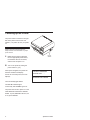
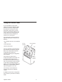
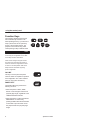
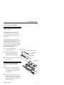
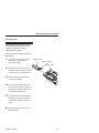
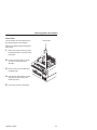
R P/N 172059–001, Rev B Communication Notices Federal Communications Commission (FCC) Statement: This equipment has been tested and found to comply with the limits for a Class A digital device, pursuant to Part 15 of the FCC Rules. These limits are designed to provided reasonable protection against harmful interference when the equipment is operated in a commercial environment. This equipment generates, uses, and can radiate radio frequency energy and, if not installed and used in accordance with the instruction manual, may cause harmful interference to radio communications. Operation of this equipment in a residential area is likely to cause harmful interference, in which case the user will be required to correct the interference at his own expense. Properly shielded and grounded cables and connectors must be used in order to meet FCC emission limits. Printronix is not responsible for any radio or television interference caused by using other than recommended cables and connectors or by any unauthorized changes or modifications to this equipment. Unauthorized changes or modifications could void the user’s authority to operate the equipment. This device complies with Part 15 of the FCC Rules. Operation is subject to the following two conditions: (1) this device may not cause harmful interference, and (2) this device must accept any interference received, including interference that may cause undesired operation. Canadian Department of Communications Compliance Statement: This Class A digital apparatus complies with Canadian ICES–003. Avis de conformite aux normes du ministere des Communcations du Canada: Cet appareil numerique de la classe A est conform á norme NMB–003 du Canada. European Community (EC) Conformity Statement: This product is in conformity with the protection requirements of EC Council Directive 89/336/EEC on the approximation of the laws of the Member States relating to electromagnetic compatibility. Printronix cannot accept responsibility for any failure to satisfy the protection requirements resulting from a non–recommended modification of the product, including the fitting of non–Printronix option cards. German Conformity Statement: Zulassungsbescheinigung Gesetz über die elektromagnetische Verträglichkeit von Geraten (EMVG) vom 30. August 1995 Dieses Gerät ist berechtigt in Übereinstimmung mit dem deutschen das EG–Konformitätszelchen – CE – zu führen. Der Außteller der Konformitätserklärung ist die Printronix......(1) Informationen in Hinsicht EMVG Paragraph 3 Abs. (2) 2: Das Gerät erfüllt die Schutzanforderungen nach EN 50082–1 und EN 55022 Klasse A. EN 55022 Klasse A Geräte bedürfen folgender Hinweise: Nach dem EMVG: “Geräte dürfen an Orten, für die sie nicht asreichend entstört sind, nur mit besonderer Genehmigung des Bundesminesters für Post und Telekommunikation oder des Bundesamtes für Post und Telekommunikation betrieben werden. Die Genehmigung wird erteilt, wenn keine elektromagnetischen Störungen zu erwarten sind.” (Auszug aus dem EMVG, Paragraph 3, Abs. 4) Dieses Genehmigungsverfahren ist nach Paragraph 9 EMVG in Verbindung mit der entsprechenden Kostenverordnung (Amtsblatt 14/93) kostenpflichtig. Nach der EN 55022: “Dies ist eine Einrichtung der Klasse A. Diese Einrichtung kann im Wohnbereich Funkstörungen verursachen; in diesem Fall kann vom Betreiber verlangt werden, angemessene Maßnahmen durchzuführen und dafür aufzkommen.” Anmerkung: Um die Einhaltung des EMVG sicherzustellen sind die Geräte, wie in den Handbüchern angegeben, zu installieren und zu betreiben. This product has been tested and found to comply with the limits for Class A Information Technology Equipment according to European Standard EN 55022. The limits for Class A equipment were derived for commercial and industrial environments to provide reasonable protection against interference with licensed communication equipment. warning This is a Class A product. In a domestic environment this product may cause radio interference in which case the user may be required to take adequate measures. Trademark Acknowledgments Printronix is a registered trademark of Printronix, Inc. IGP is a registered trademark of Printronix, Inc. PhoenixPage PCL 5 is a registered trademark of Phoenix Technologies Ltd. HP is a registered trademark of Hewlett–Packard Company. PCL is a trademark of Hewlett–Packard Company. 14600 Myford Road, P.O. Box 19559 Irvine, California 92713 Telephone (714) 368–2300 FAX (714) 368–2600 Technical Support (714) 368–2686 COPYRIGHT 2000, PRINTRONIX, INC. Printronix wants you to feel comfortable and confident using the Continuous Form Laser Printer and this guide. This guide is designed to meet the needs of all users, from beginners to those experienced with page printers. Follow the directions in this guide along with those in your Setup Guide in order to avoid injury to you and damage to the printer. Conventions Notes, Cautions, and Warnings Notes provide supplemental information that could affect printer operation or use. note Cautions describe conditions that could damage the printer. caution Warnings describe conditions that could harm you as well as damage the equipment. warning Message Display These boxes show display messages as they appear on the printer. ON LINE Hardware Options ................................................... 1 Powering up the Printer . . . . . . . . . . . . . . . . . . . . . . . . . . . . . . . . . . . . . . . . . . . . . . . 2 Using the Control Panel . . . . . . . . . . . . . . . . . . . . . . . . . . . . . . . . . . . . . . . . . . . . . . . 4 Loading Paper . . . . . . . . . . . . . . . . . . . . . . . . . . . . . . . . . . . . . . . . . . . . . . . . . . . . . . . 9 Media Requirements . . . . . . . . . . . . . . . . . . . . . . . . . . . . . . . . . . . . . . . . . . . . . . . . . 11 Clearing Paper Jams . . . . . . . . . . . . . . . . . . . . . . . . . . . . . . . . . . . . . . . . . . . . . . . . 12 Cleaning the Printer . . . . . . . . . . . . . . . . . . . . . . . . . . . . . . . . . . . . . . . . . . . . . . . . . 18 Adjusting the Print Image . . . . . . . . . . . . . . . . . . . . . . . . . . . . . . . . . . . . . . . . . . . . . 21 Replacing Printer Consumables . . . . . . . . . . . . . . . . . . . . . . . . . . . . . . . . . . . . . . . 22 Status and Error Messages . . . . . . . . . . . . . . . . . . . . . . . . . . . . . . . . . . . . . . . . . . . 34 Consumables Information Consumables design, specification, and selection are critical and integral to the development of any computer printer imaging system. Printronix’s extensive manufacturing and research capabilities, along with years of experience in the design of printers and their applications, assures that you receive the exact materials you require to maximize the performance of your printer. For the name of your nearest Printronix full service distributor, please call: United States Europe Singapore * (800) 733–1900 (33) 1-46-25-1900 (65) 548–4116 Part Number Description Life (in pages) * 704539–006 Toner Kit: 2 Toner Bottles 2 Fuser Felts 2 Waste Toner Bottles 16,000 (8,000 pages per item) 704539–008 OPC 30,000 704539–007 Developer Kit: Developer Unit Starter Toner Ozone Filter Cleaner Kit 100,000 704539–011 Fuser Felts Replace as needed to maintain print quality 704539–012 ** Fuser Unit, 120V 300,000 704539–013** Fuser Unit, 230V 300,000 Consumable life is based on a 5% page density using 20 lb. bond paper. Use of other media types and weight will affect consumable life. ** The fuser module is a service replaceable consumable. This module, though purchased by the end–user, should be replaced by your authorized service representative. The following hardware options are available for the printer. • Paper stacker with printer stand The paper stacker provides for properly stacked paper from the beginning to completion of the print job. The stacker supports form lengths from 9.0 to 14.0 inches and will hold an entire box of paper. • DRAM Memory expansion (64 MB) The printer has 32 MB of DRAM memory factory installed as a standard configuration. • Flash Memory (16 and 32 MB) The printer has 8 MB of flash memory factory installed as a standard configuration. • Local Area Network (LAN) connection A hardware option is available for connecting the printer to a LAN. • Coax/Twinax connection A hardware option is available for connecting the printer for Coax/Twinax operation. • Optional fonts Optional printer fonts can be purchased and loaded into the printer. Operator’s Guide 1 The power switch is located on the right side of the printer near the rear. It is marked f for power off, and | for power on. note Refer to the power requirements in the Setup Guide for more information on proper power sources. 1 2 Power Switch Make sure the printer is plugged into the appropriate power source, the interface cable is connected, and the host computer is on. Turn on the printer by setting the power switch to | (on). When power is applied, the printer will read the emulation and display: TESTING HARDWARE PLEASE WAIT. . . . . If there are no bootup errors, the LCD displays: DIAGNOSTICS PASSED Then the standby light flashes. The ONLINE indicator lights continuously and STANDBY goes out. The printer can be set to power on in the OFFLINE state instead of the ONLINE STATE. To print, ONLINE must be lit; if it is not, press ONLINE. 2 Operator’s Guide Using the Control Panel If your self adhesive control panel overlay has not been attached, please attach it. The printer is shipped with a thin plastic film covering the control panel plastic housing keys. This film must be removed before attaching the overlay. Remove the backing from the control panel overlay and apply the overlay to the control panel. The control panel, located on the front right side of the printer, consists of the following: • An LCD with two lines of 16 characters each • Three indicators • Seven function keys On Line Indicator Check Indicator LCD The LCD, indicators, and function keys are described in the following sections. Refer to the Setup Guide for specific configuration procedures and information regarding the configuration menu structure. The function keys permit you to configure the options of the printer. You can access these selections via a structured menu of options and values which are presented through messages on the LCD. To navigate through the options, use the UP, DOWN, NEXT, and PREV keys. Press ENTER to select an option that appears on the LCD. Job In Process Indicator The enter key can be locked and unlocked. The power up default is “locked.” A detailed overview of the configuration menu structure is provided in the Setup Guide. Operator’s Guide 3 using the control panel Liquid Crystal Display Located at the top of the control panel, the two–line LCD does the following: • Displays printer status and fault codes. Refer to the “Status and Error Messages” section for instructions on correcting fault conditions. • Displays information for the diagnostics menu display of engine life data. • Displays each item in the configuration menu as you navigate through the menu to make selections. 4 Operator’s Guide using the control panel Indicators The three indicators on the control panel display the current operational status of the printer. ON LINE ON LINE lights when the printer is online, or when the printer is ready to print and accept data from the host. It flashes when the printer is offline. When the printer stops because of an error, the printer goes offline and the ON LINE light flashes. CHECK CHECK flashes when the printer is unavailable for printing because of an internal fault condition. JOB IN PROCESS When the printer is receiving or processing data, JOB IN PROCESS flashes. If data has been processed and is waiting to be printed, JOB IN PROCESS is lit continuously. JOB IN PROCESS is not on when: • The printer is not processing data and no data exists in the buffer. • The printer is not receiving data. Operator’s Guide 5 using the control panel Function Keys The pressure–sensitive function keys are located directly below the LCD. When pressing the keys, you will hear a “beep” (also known as the “panel key sound”), which verifies contact. The purpose of each function key (under normal printing mode) is defined below. ON LINE PREV UP DOWN NEXT You can enable or disable the panel key sound using the configuration menu. Refer to the Setup Guide for information. Printer values changed using the function keys will not be saved when the printer is turned off unless the configuration is saved as shown in the Setup Guide. Refer to the Setup Guide for information regarding printer configuration. ON LINE ON LINE This key is used to place the printer online or offline as required for operation and configuration. The online indicator works in conjunction with this key. PAGE EJECT The PAGE EJECT key performs the following functions: • When the printer is offline, PAGE EJECT moves the paper forward one physical page length, regardless of the JOB IN PROCESS indicator. • When the printer is online and JOB IN PROCESS is on continuously, pressing PAGE EJECT allows the data in the buffer to print and then moves the paper forward one physical page length. 6 Operator’s Guide using the control panel • If the printer is online and the JOB IN PROCESS indicator is not on, PAGE EJECT will move paper one physical page length. • When the printer is online and JOB IN PROCESS is flashing, pressing PAGE EJECT causes the printer to attempt to print any data in the buffer. The paper motion caused by the page eject operation may interrupt the printing of data that is not currently in the buffer. Once the paper motion has occurred, the data will print. ENTER When the printer is offline and the LCD shows a desired configuration value, press ENTER to select the value. The printer will confirm your selection by placing an asterisk (*) next to the value in the LCD. Press UP and DOWN simultaneously to toggle the ENTER key lock. The ENTER key must be unlocked to enter configuration selections. UP or DOWN When the printer is offline and in the configuration menu, either press UP or DOWN to move between the different levels of the menu. UP DOWN Press UP and DOWN simultaneously to toggle the ENTER key lock. The ENTER key must be unlocked to enter configuration selections. The ENTER key must be unlocked when changing configuration settings. Operator’s Guide 7 using the control panel NEXT or PREV When the printer is in the configuration menu, press NEXT or PREV to move between the options on the current menu level. The NEXT and PREV function keys can also be used, together and in conjunction with other keys, to perform a Cancel and a Reset function. The cancel function will not stop the host computer from sending more data to the input buffer. Make sure the host computer cancels the print job. Cancel Function The Cancel function will terminate all jobs, clear the data input buffer, clear any bit maps that have been formed, and extinguish the JOB IN PROCESS light. If the printer is offline, but there is a job in process, pressing NEXT and PREV simultaneously will perform the Cancel function. If the printer is online or if there is no job in process, this cancel function will have no effect. The cancel function may perform additional operations depending on the emulation being used. See your emulation documentation for more information. PREV Cancel Function Reset Function The Reset function is used to clear any error condition where “Call Service” appears on the second line of the control panel LCD. When “Call Service” is displayed on the LCD, press the UP and NEXT function keys simultaneously to perform the Reset function. If the error condition continues after the reset function, contact your authorized service provider. 8 UP Reset Function Operator’s Guide note Verify that all installation procedures in the Setup Guide have been completed before loading the paper. Top Cover Latch Before loading paper, make sure the Paper Length and Paper Width options are set properly in the Paper Control configuration menu. Refer to the Setup Guide for details. Verify that the media meets the requirements as described on page 11. Tension Release To load paper: 1 2 3 4 5 6 Raise the top of the printer by firmly pressing the top cover latch on the left side of the front panel. Insert paper into the front of the printer. Press the tension release as required to insert the paper. Unlock the tractors by pushing up the tractor locks. Paper Entrance Tractor Gate Tractor Pins Tractor Locks Adjust the width of the tractors so that the paper is in the proper position. Open the tractor gates on the tractor unit, place the paper on the pins, and close the tractor gates. Lock the tractor unit by pushing down on the tractor locks. Operator’s Guide 9 7 To ensure that the printer will start at the top of a page, check the following: • The leading edge should be straight; not torn, crooked, or curled. • The leading edge of the paper should not extend beyond the tractors. This allows the printer to set the top of form accurately and automatically at the leading edge of the paper. 8 Close the top cover of the printer. After the paper is loaded and the top cover is closed, the printer automatically sets the top of form at the leading edge of the paper. ON LINE must be lit to begin printing. If it is not, press the ON LINE key. note Repeat the paper loading procedure whenever top of form must be reset (e.g., after clearing a paper jam, loading new paper, etc.). For details on clearing paper jams, refer to the “Clearing Paper Jams” section. If the printer runs out of paper during printing, you do not need to turn power off to replace paper. If power is maintained, the printer will resume printing automatically after the paper has been replaced. 10 Operator’s Guide The printer requires continuous form media with 0.5 inch pitch tractor feed pin holes. The media capabilities and requirements are listed in the following table: Dimension Specification Width 4.0 to 10.0 inches edge to edge (3.5 to 9.5 inches pin to pin) Length 3.0 to 33.0 inches in 1/8 or 1/6 inch increments Weight 18 to 42 lb. bond 110 lb. tag stock 99 lb. card stock Labels: Face Stock Carrier Adhesive 40 to 60 lb. book stock 50 lb. book stock acrylic Cut to Tie (page perf) ≥ 2.9:1 (8 cuts/inch) bond (and microperf) ≥ 6.5:1 (4 cuts/inch) tag/card stock ≥ 6.5:1 (4 cuts/inch) label stock Percent Recycled paper 20% maximum Moisture Content 5% + 1% Resistivity 108 to 1012 ohms Bond paper weight based on 17 X 22 inch base size. Tag stock based on 24 X 36 inch base size. Card stock based on 22 1/2 X 28 1/2 inch base size. Book carrier stock based on 25 X 38 inch base size. Operator’s Guide 11 When a paper jam occurs, the printer stops, displays an error message, and saves the page (image) in a buffer for reprinting. Paper jams can be caused by several problems, including: 06 CLEAR JAM AT FUSER INPUT • Using paper of the wrong weight • Using paper that is wrinkled • Using paper that does not have a straight edge on the first page, causing improper automatic top of form setting 07 CLEAR JAM AT FUSER EXIT 08 CLEAR JAM NEAR TOF LEVER • Placing paper improperly on the tractors During normal operation, the paper feeds smoothly through the printer. However, paper jams can result. When a paper jam occurs the LCD shows one of the adjacent messages: 09 CHECK TOF LEVER 19 PAPER CTL ERR Reload Paper When a paper jam occurs, the toner has not been fused to the paper still inside of the printer. Be careful not to stain your hands, clothes, or the interior of the printer with toner. If toner is spilled, use a toner vacuum to clean up the loose toner. Do not use water to clean the toner from the printer. Any toner remaining on clothes can be removed with a cloth dampened in cold water; never use hot water to remove toner from clothes or skin. 12 Operator’s Guide After removing the jammed paper, reload paper as described in the “Loading Paper” section. To clear the printer, close the top cover and press ON LINE. For most emulation modes, the jammed pages will automatically be reprinted. After printing, verify that no pages remain unprinted. If a paper jam occurs while running either a test print or a configuration printout, pressing online is not necessary to resume printing. Jam at Fuser Input warning The fuser operates at extremely high temperature. Avoid touching the fuser. Refer to the adjacent figure and perform these steps: 1 2 3 4 5 Raise the top of the printer by firmly pressing the button on the left side of the front panel. OPC Drum Tear off the paper at the perforation nearest the OPC drum unit and remove the paper. Perforation Reload the paper. Refer to the “Loading Paper” section. Close the top cover of the printer and wait for the printer to warm up. Loose Toner Paper Jam Press ON LINE. Printing will resume. Operator’s Guide 13 Jam at Fuser Exit warning The fuser operates at extremely high temperature. Avoid touching the fuser. Refer to the adjacent figure and perform these steps: 1 2 Raise the top of the printer by firmly pressing the button on the left side of the front panel. OPC Drum Tear the paper at a perforation between the OPC drum unit and the fuser unit. Perforation Fuser Unit 3 Open the rear cover of the fuser unit by rotating it back and down. caution Pull the jammed paper toward the rear cover of the fuser unit only. Pulling the paper back over the rollers may damage the top of form sensor. Fuser Roller Paper Jam Pressure Roller Rear Cover Be careful not to scratch or nick the rollers when removing the jammed paper. 4 5 6 7 8 14 Carefully pull the jammed paper from between the fuser roller and the pressure roller. Close the rear cover of the fuser unit. Reload the paper. Refer to the “Loading Paper” section. Close the top cover of the printer and wait for the printer to warm up. Press ON LINE. Printing will resume. Operator’s Guide Tractor Feed warning The fuser operates at extremely high temperature. Avoid touching the fuser. Refer to the adjacent figure and perform these steps: 1 2 3 4 Raise the top of the printer by firmly pressing the button on the left side of the front panel. Open the rear cover of the fuser unit by rotating it back and down. OPC Drum Pull and remove the tractor feed strips from between the fuser rollers or the tractor feed strips between the tractors. Perforation Fuser Unit At the closest perforation, tear off the paper and pull it out from the back of the fuser rollers in the fuser unit. caution Pull the jammed paper toward the rear cover of the fuser unit only. Pulling the paper back over the rollers may damage the top of form sensor. Tractor Feed Strip Rear Cover Be careful not to scratch or nick the rollers when removing the jammed paper. 5 6 7 8 Reload the paper. Refer to the “Loading Paper” section. Close the rear cover of the fuser unit. Close the top cover of the printer and wait for the printer to warm up. Press ON LINE. Printing will resume. Operator’s Guide 15 Skewed Paper warning The fuser operates at extremely high temperature. Avoid touching the fuser. OPC Drum Refer to the adjacent figure and perform these steps: 1 2 3 4 Perforation Raise the top of the printer by firmly pressing the button on the left side of the front panel. Tear the paper at a perforation between the OPC drum unit and the fuser unit. Open the rear cover of the fuser unit by rotating it back and down. Fuser Unit Fuser Roller Pressure Roller Rear Cover Carefully pull the paper between the fuser roller and the pressure roller toward the rear cover of the fuser unit. caution Pull the jammed paper toward the rear cover of the fuser unit only. Pulling the paper back over the rollers may damage the top of form sensor. Be careful not to scratch or nick the rollers when removing the jammed paper. 5 16 Close the rear cover of the fuser unit. Operator’s Guide note Make sure that the width of the tractors are set to match the paper width and the paper is properly placed on the tractor feed pins. 6 7 8 Reload the paper. Refer to the “Loading Paper” section. Close the top cover of the printer and wait for the printer to warm up. Press ON LINE. Printing will resume. Operator’s Guide 17 Perform these general cleaning procedures on a regular basis to keep the printer operating properly. During normal printer operation, dust, dirt, toner, and paper chaff will accumulate. However, excess accumulation can affect printer operation and print quality. warning To prevent possible injury to yourself or damage to the printer, make sure the printer is turned off and disconnected from the power source during the cleaning process. caution Strong cleaners, such as isopropyl alcohol, ethanol, and methanol, can cause cracks after prolonged use and are not suggested. To clean the exterior surface of the printer, use water or a mild cleaning agent (such as dishwashing soap) and a soft cloth to wipe the surfaces clean. Always apply the cleaning agent to the cloth; never pour the cleaning agent directly onto the printer. 18 Operator’s Guide Cleaning the Corona Wires note Clean the corona wires as needed, or each time toner is added. The illustration with the procedure shows the developer unit removed. This is for ease of illustration only. The developer unit does not need to be removed to clean the corona wires. The printer has two corona wires that may affect print quality. One is in the top of the OPC drum unit; the other is directly underneath it, inside the printer. If a print shows a vertical streak through the whole page (light or white), the corona wires may be dirty. 1 2 3 Power off the printer and unplug the power cord. Brush Storage Raise the top of the printer by firmly pressing the button on the left side of the front panel. Corona Cleaning Brush Corona Wire Cover Corona Wire Lift the corona wire cover from the OPC drum unit. caution Corona Wire Be careful not to break the delicate corona wire. Do not press down too hard. 4 5 Slide the corona cleaning brush, located in the top of the OPC drum unit, along the corona wire in the OPC drum unit. Replace the corona wire cover on the OPC drum unit. The corona wire cover is marked with “L” and “R” to indicate the left right reference, and will snap into place. Operator’s Guide 19 caution The OPC drum unit is light sensitive. Install it within five minutes. If the OPC drum can not be installed within five minutes, place the drum in the original packaging to prevent light damage. When removing the drum unit, do not touch the surface of the drum unit. Fingerprints and scratches can damage the drum surface and cause poor print quality. Do not rotate the drum unit manually. Forced rotation will cause an incorrect count for the life of the drum unit and may cause poor print quality. 6 7 8 9 Remove any paper from the printer. Remove the OPC drum unit from the printer by lifting up and out. Set the unit aside. Slide the corona cleaning brush along the length of the transfer corona wire to remove any dust or debris. Place the OPC drum unit into the printer. 10 Replace the corona cleaning brush in its holder on top of the OPC drum unit. 11 Reload the paper. Refer to the “Loading Paper” section. 12 Close the top cover of the printer and wait for the printer to warm up. 20 Operator’s Guide The following table lists possible print quality problems and a brief description of the corrective action required. If the corrective action does not fix the problem, clean the corona wires or call your authorized service technician. Problem Corrective Action Skewed print Properly reset the paper on the tractors. (See the “Skewed Paper” section on page 16.) Wrong character size; wrong font Make sure that your software asks for the right font. In addition, make sure the font is available on the printer disk or has been downloaded to printer RAM. Light print on one side; dark print on the other Remove the developer unit and gently rock it side to side to evenly distribute the toner. Replace the developer unit into the printer; resume printing. Properly set the green locking clamps on the developer unit. Uniformly light prints Locate the green print density knob located along the left side of the printer. Turn the knob clockwise to darken the print (more toner will be consumed). Check the LCD for error messages. If “ADD TONER AND CHK WASTE BOTTLE” appears, add toner. Check the number of copies, and, if necessary, replace the OPC drum unit. (See the section on replacing printer supplies, page 22.) Uniformly dark prints Locate the green print density knob located along the left side of the printer. Turn the knob counterclockwise to lighten the print (less toner will be used). If all printer consumables have been replaced and image defects and/or paper creases persist, the fuser may need to be replaced. The fuser is the unit that heats the toner so that it adheres to the paper. When the fuser is worn, print quality may deteriorate. On average, the fuser should provide optimum print quality for 300,000 pages when using paper rated between 16 and 25 pounds. Label stock and other heavier media may reduce the life of the fuser. Contact your authorized service representative for fuser replacement. Operator’s Guide 21 Printer consumable supplies should be changed when the number of pages printed reaches the maximum amounts shown in the following table. This document contains the procedures for replacing all components with the exception of the fuser unit. Since some disassembly is required for replacement of the fuser unit, this replacement is covered in the Maintenance Manual. Each consumable component contributes to the consistent high quality available from the printer. When you buy original manufacturer consumables, you buy world class quality. And total quality commitment to our customer is our highest priority. This guarantee assures your complete satisfaction for performance and reliability. The material in the toner kit is recyclable. Save the toner box and packaging materials for recycling. A recycling shipping label is provided with instructions attached. Part Number Description Life (in pages) 704539–006 Toner Kit: 2 Toner Bottles 2 Fuser Felts 2 Waste Toner Bottles 16,000 (8,000 pages per item) 704539–008 OPC Drum Unit 30,000 704539–007 Developer Kit: Developer Unit Starter Toner Ozone Filter Cleaner Kit 100,000 704539–011 Fuser Felts Replace as needed to maintain print quality 704539–012 Fuser Unit, 120V 300,000 704539–013 Fuser Unit, 230V 300,000 22 Operator’s Guide replacing printer consumables Consumables design, specification, and selection are critical and integral to the development of any computer printer imaging system. The yield of the supplies is based on a 5% page coverage using 20 lb bond paper. In a typical business letter, for example, text covers approximately 5% of the page. However, applications that print more densely, such as graphics and bar codes, will use the consumables at a faster rate. In addition, the type of media used will determine the yield of the consumables. Optimum print quality and consumable life is obtained by using bond media rated between 18 and 20 pounds. Label stock and heavier media can also be used, but the print quality and consumable life, as well as the life of the fuser, may be reduced. Refer to the “Media Requirements”on page 11. When a consumable needs to be replaced, an appropriate message will be displayed on the LCD. Refer to “Status and Error Messages” on page 34 for a description of possible messages. Operator’s Guide 23 replacing printer consumables note The following applies to all replacement procedures: Be careful not to stain your hands, clothes, or the interior of the printer with toner. If toner is spilled, use a toner vacuum to clean up the loose toner. Do not use water to clean the toner from the printer. Any toner remaining on clothes can be removed with a cloth dampened in cold water; never use hot water to remove toner from clothes or skin. Adding Toner caution Do not add toner until the printer displays a toner low message. Replace the fuser cleaner felt and waste toner bottle every 8,000 pages of printing or each time a new toner bottle is opened, except when replacing starter toner. The toner kit contains two toner bottles, two fuser cleaner felts, and two waste toner containers. A single bottle of toner is rated for approximately 8,000 pages, based on a 5% page coverage. Most applications will yield an amount close to this rating. However, your yield may vary according to your print application. Toner is light and easily becomes airborne and can contaminate the printer. 24 Operator’s Guide replacing printer consumables note If toner is spilled, use a toner vacuum to clean up the loose toner. Do not use water to clean the toner from the printer. Any toner remaining on clothes can be removed with a cloth dampened in cold water; never use hot water to remove toner from clothes or skin. Use care when handling toner. Do not turn off the printer during a print job to add toner; otherwise, all unprinted data will be lost. Once the toner is added and the cover is closed, press ON LINE to continue printing. When the toner is low, the printer will stop and the LCD will show: 03 ADD TONER AND CHK WASTE BOTTLE Refer to the adjacent figure and perform these steps: 1 2 3 Raise the top of the printer by firmly pressing the button on the left of the front panel. Developer Unit Cover (shown in the open position) Open the toner bottle and attach the spout. Carefully open the developer unit cover. caution Do not squeeze the toner bottle as you pour the toner. Doing so could cause the loose toner to be blown out of the hopper and contaminate the printer and soil hands and clothes. If the toner bottle does not empty completely, gently tap the end of the bottle while holding it over the hopper. 4 Toner Bottle (with spout attached) Carefully pour the toner into the developer unit. Make sure to spread the toner evenly from side to side. Operator’s Guide 25 replacing printer consumables 5 6 Tap the toner bottle several times to loosen toner. Close the developer unit cover. Press until you hear a “click” which indicates that the developer unit is closed completely. note It is not necessary to replace the waste toner bottle or fuser felt if the toner that was last added was toner from a starter toner bottle. caution Failure to replace the waste toner bottle, after using a standard toner bottle, can cause a toner overflow, requiring a service call to properly clean the printer. 7 8 Replace waste toner bottle and fuser felt if it is 2/3 full, or more. Close the printer top cover. note Some software stops communicating with the printer if the printer is offline for more than two minutes. In this case, you may need to restart your print job. 26 Operator’s Guide replacing printer consumables Fuser Cleaner Felt The fuser cleaner felt should be replaced each time a new toner bottle is opened, except when replacing starter toner. The cleaner felt should also be replaced when toner has built up on the felt and begins to flake off. Be sure to monitor print quality and condition of the cleaner felt. Replace the fuser cleaner felt if print quality deteriorates and caked toner is found on the cleaner felt. warning The fuser operates at extremely high temperatures. The fuser and fuser cleaner felt may be very hot. Use caution when performing this procedure. Refer to the adjacent figure and perform these steps: 1 2 3 4 5 Raise the top of the printer by firmly pressing the button on the left of the front panel. Fuser Cleaner Felt Fuser Cleaner Felt Cover (shown in the open position) Open the fuser cleaner felt cover. This cover is hinged and will not be removed. Remove the old cleaner felt by lifting it straight up and out the top of the fuser. Place the new fuser cleaner felt in the top of the fuser and close the fuser cleaner felt cover. Close the printer cover. Operator’s Guide 27 replacing printer consumables Waste Toner Container The waste toner container must be replaced each time a new toner bottle is opened, except when replacing start toner. note If toner is spilled, use a toner vacuum to clean up the loose toner. Do not use water to clean the toner from the printer. Any toner remaining on clothes can be removed with a cloth dampened in cold water; never use hot water to remove toner from clothes. Use care when handling toner. Refer to the adjacent figure and perform these steps: 1 Raise the top of the printer by firmly pressing the button on the left of the front panel. OPC Drum Unit Waste Toner Container caution Handle the OPC drum unit with care. The OPC drum unit can be damaged by extended exposure to light and the drum is easily scratched. Place the unit on a flat surface while it is not in the printer. 2 3 4 28 Remove the OPC drum unit by lifting it carefully out of the printer and place it on a flat surface. Before removing the waste toner container, place the green cap over the filling hole. Once in place, the green cap can not be removed. Remove the old waste toner container from the printer and discard. Operator’s Guide replacing printer consumables note The waste toner container must be properly seated in the printer or the printer will display an error message when the printer cover is closed. 5 6 7 Place the new waste toner container in the printer in the same position as the old one. Carefully replace the OPC drum unit. The OPC drum unit is not held in place and rests in the printer. Close the printer cover. Operator’s Guide 29 replacing printer consumables OPC Drum Unit The OPC drum unit is replaced after 30,000 pages have been printed. The OPC drum unit may need to be replaced if there is background shading in unprinted areas. caution OPC Drum Unit Handle the OPC drum unit with care. The OPC drum unit can be damaged by extended exposure to light and the drum is easily scratched. Refer to the adjacent figure and perform these steps: 1 2 3 4 5 30 Raise the top of the printer by firmly pressing the button on the left of the front panel. Remove the OPC drum unit by lifting it carefully out of the printer and place it on a flat surface. Use the appropriate material and pack the used OPC drum for recycling. Carefully place the new OPC drum unit into the printer. The OPC drum unit is not held in place and rests properly in the printer. Close the printer cover. Operator’s Guide replacing printer consumables Developer Unit caution When replacing the developer unit, you must fill the unit using the starter toner. The starter toner bottle contains magnetic carrier and toner. Refer to the adjacent figure and perform these steps: 1 Unlock the old developer unit by pushing up on the two green lock–down clamps. Developer Unit Roller (not shown) Green Clamp 2 3 4 5 6 Slide the developer unit out along the plastic rails on either side of the printer and pull it out of the printer. Remove the new developer unit from the foil package. Hold the new developer unit with the roller facing into the printer and slide the unit along the plastic rails on either side of the printer. Lock the developer unit in place by pushing the two green lock–down clamps down until they click into place. Move the developer unit to verify that it is locked. Operator’s Guide 31 replacing printer consumables caution Only add Starter Toner to the developer unit during installation. DO NOT ADD TONER. Toner should only be added following a toner low message on the control panel LCD. (The starter toner will print approximately 200 pages at 5%.) The procedure on page 24 shows a toner bottle being used. Make sure you use starter toner from the developer unit kit. 7 8 9 32 Add the starter toner that comes with the developer unit kit in the same manner as directed on page 24. Verify that the developer unit cover is closed. Close the top cover of the printer. Operator’s Guide replacing printer consumables Ozone Filter The ozone filter must be replaced every time the developer unit is replaced. Ozone Filter Refer to the adjacent figure and perform these steps: Raise the top of the printer by firmly pressing the button on the left of the front panel. Pull the old ozone filter, by its tab, up and out of the printer and discard it. Remove the new ozone filter from the plastic bag. Hold the new ozone filter by its tab and place the filter into the slot inside the printer. Close the top cover of the printer. Operator’s Guide 33 You can correct most faults by performing a simple procedure, such as clearing a paper jam or reloading paper. For more serious faults, a field service representative may be needed. Errors not described in this guide can be found in your Setup Guide. The following is a list of status messages. These messages inform you of the operational condition of the printer. They do not indicate an error situation. Status Messages Message 34 Description RUNNING SELF TEST .... Displayed during printer power–up, this message indicates that the printer is running internal diagnostics. ONLINE The printer is online. OFFLINE The printer is offline. STANDBY The printer is accessing the disk (e.g., loading or saving configurations). TEST PRINTING The test print function has been activated. The printer prints test page(s). Operator’s Guide Error Messages This section provides a description of error messages that indicate possible printer problems. Note that these errors are warnings only, and do not cause the print job to be lost. Once the corrective action has been taken, printing will resume. Message Problem Corrective Action 01 CLOSE THE COVER The printer cover is open. Close the cover. 02 LOAD PAPER Printer is out of paper. Load paper. Refer to page 9. 03 ADD TONER AND CHK WASTE BOTTLE Printer is out of toner. Add toner and check waste toner bottle level. Refer to page 24. 04 INSTALL TONER CUP Toner waste bottle is not installed or not detected. Install or reseat toner waste bottle. 05 INSTALL OPC DRUM The OPC drum unit is not installed or not detected. Install or reseat the OPC drum unit. 06 CLEAR JAM AT FUSER INPUT Entry jam sensor is on. Clear the paper jam. Refer to page 13. 07 CLEAR JAM AT FUSER EXIT Exit jam sensor is on. Clear the paper jam. Refer to page 14. 08 CLEAR JAM NEAR TOF LEVER Jam occurred in paper path. Clear the paper jam. Refer to page 15. O9 CHECK TOF LEVER Top of form sensor malfunction. Inspect top of form sensor lever and call service if necessary. 19 PAPER CTL ERR Reload Paper A paper motion error has been detected. Burst paper at tractors and reload paper. Refer to page 9. 34 REPLACE OPC DRUM Call Service The OPC drum unit has exceeded its life of 30,000 printed pages. Replace the OPC drum unit. Operator’s Guide 35 Fatal Error Messages This section provides a description of error conditions that cause printing to stop. These errors are provided for information only. The corrective action in all cases is to first perform the reset function (described on page 8). If the printer reset does not solve the problem, cycle the printer power. If a reset or power cycle does not solve the problem, call your authorized service representative. Message 36 Problem 15 FUSER FAIL Call Service A rotation error of the pressure roller cam has occurred. There is an unfused image at fuser. 16 FUSER FAIL Call Service Pressure roller cam did not stop or is out of position after stop attempt or the sensor is bad. 17 FUSER FAIL Call Service Pressure roller cam did not start or the sensor is bad. 18 FUSER FAIL Call Service The sensor that detects the position of the speed control plate is defective. 23 THRMISTR FAIL Call Service Thermistor wire broken or thermistor is open. 24 THRMISTR FAIL Call Service Thermistor shorted or extraordinarily high temperature. 25 ENCODER FAIL Call Service Defective or dirty encoder needs to be replaced. 26 HEATER FAIL Call Service Fuser did not warm up within specified time. 27 HEATER FAIL Call Service Fuser temperature not maintained during printing. 28 BEAM DET FAIL Call Service Beam detect failure. Motor spinning but not generating interrupts. Operator’s Guide Message Problem 29 LSU FAIL Call Service No “ready” returned from LSU phase lock circuit. 30 LSU FAIL Call Service LSU phase lock lost. 31 LSU FAIL Call Service “Ready” returned from LSU phase lock circuit but LSU motor not enabled. 32 MISPRINT ERROR Call Service Failed handshaking between engine and CPU controller board. 33 REPLACE EEPRM Call Service Engine controller EEPROM has exceeded its life expectancy of 100,000 writes. 35 EC CKSUM FAIL Call Service A checksum error occurred while reading the EEPROM on the engine controller board. Operator’s Guide 37 38 Operator’s Guide (! ! ' !% ' ! % ' $&& & # #!" ' "$# "#!# "$# $"#! "## " ! ' 172059–001B