1
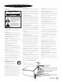
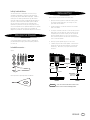
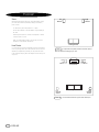
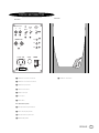
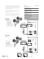
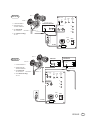
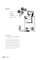
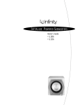
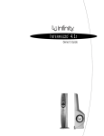
INTERLUDE™ SPEAKER SYSTEMS
Owner’s Guide
• IL50
• IL60
CAUTION
RISK OF ELECTRIC SHOCK
DO NOT OPEN
WARNING: SHOCK HAZARD, DO NOT OPEN.
AVIS: RISQUE DE CHOC ELECTRIQUE – NE PAS OUVRIR.
CUIDADO: PELIGRO DE CHOQUE ELÉCTRICO – NO ABRIR.
CAUTION: TO REDUCE THE RISK OF ELECTRIC SHOCK
DO NOT REMOVE COVER (0R BACK)
NO USER SERVICEABLE PARTS INSIDE
REFER SERVICING TO QUALIFIED PERSONNEL
THIS INFINITY PRODUCT IS DESIGNED FOR 120-VOLT USE ONLY! FOR
DETAILED SAFETY PRECAUTIONS, PLEASE SEE FOLLOWING PAGE IN THIS
OWNER’S MANUAL FOR “IMPORTANT SAFETY INSTRUCTIONS.”
The lightning flash with arrowhead symbol, within an equilateral triangle, is
intended to alert the user to the presence of uninsulated “dangerous voltage” within
the product’s enclosure that may be of sufficient magnitude to constitute a risk of
electric shock to persons.
The exclamation point within an equilateral triangle is intended to alert the user
to the presence of important operating and maintenance (servicing) instructions in
the literature accompanying the product.
L’éclair avec le symbole de la flèche, placé dans les limites d’un triangel équilatéral est
prévu pour avertir l’utilisateur de la présence de “tension dangereuse” non isolée dans
l’enceinte du produit qui pourrait être d’une importance suffisante pour présenter un
risque d’électrocution aux personnes.
Le point d’exclamation dans un triangel équilateral est prévu pour avertir l’utilisateur
de la présence d’instructions importantes pour les opérations et l’entretien (service)
dans les manuels fournis avec l’appareil.
ATTENTION: POUR EVITER LES CHOCS ELECTRIQUES, INTRODUIRE
LA LAME LA PLUS LARGE DE LA FICHE DANS LA BORNE
CORRESPONDANTE DE LA PRISE ET POUSSER JUSQUAU FOND.
Este destello luminoso con un símbolo de punta de flecha dentro de un triángulo
equilátero tiene el objectivo de alertar al usuario sobre la presencia de “voltaje
peligroso” no aislado dentro de la caja del producto que puede ser de magnitud lo
suficientemente grande para constituir un riesgo de choque eléctrico para las personas.
Este punto de exclamación dentro de un triángulo equilátero tiene el objectivo de
alertar al usuario sobre la existencia de instrucciones operativas y de mantenimiento
(servicio) importantes en la literatura que acomaña el aparato.
CUIDADO: PARA REDUCIR EL RIESGO DE CHOQUE ELÉCTRICO, NO
RETIRE LA CUBIERTA (O RESPALDO). DENTRO NO HAY PEIZAS A LAS
QUE EL USUARIO PUEDE DAR SERVICIO. REMITA EL SERVICIO AL
PERSONAL DE SERVICIO CALIFICADO.
ii
INTERLUDE
IMPORTANT SAFETY PRECAUTIONS
Read First!
CAUTION
RISK OF ELECTRIC SHOCK
DO NOT OPEN
The lightning flash with arrowhead
symbol within an equilateral triangle is
intended to alert the user to the presence
of uninsulated “dangerous voltage” within
the product’s enclosure that may be of
sufficient magnitude to constitute a risk of
electric shock to persons.
The exclamation point within an
equilateral triangle is intended to alert the
user to the presence of important
operating and maintenance (servicing)
instructions in the literature accompanying
the appliance.
1. Read Instructions. All the safety and operating
instructions should be read before the product is
operated.
2. Retain Instructions. The safety and operating
instructions should be retained for future reference.
3. Heed Warnings. All warnings on the product and in
the operating instructions should be adhered to.
4. Follow Instructions. All operating and use
instructions should be followed.
5. Cleaning. Unplug this product from the wall outlet
before cleaning. Do not use liquid cleaners or aerosol
cleaners. Use a damp cloth for cleaning.
6. Attachments. Do not use attachments not
recommended by the product manufacturer,
as they may cause hazards.
7. Water and Moisture. To reduce the risk of fire or
electric shock, do not use this product outdoors or
near water–for example, near a bathtub, wash bowl,
kitchen sink or laundry tub; in a wet basement; near a
swimming pool; or the like.
8. Accessories. Do not place this product on an
unstable cart, stand, tripod, bracket or table.The
product may fall, causing serious injury to a child or
adult, and serious damage to the product. Use only
with a cart, stand, tripod, bracket or table
recommended by the manufacturer, or sold with the
product. Any mounting of the product should follow the
manufacturer’s instructions, and should use a
mounting accessory recommended by the
manufacturer.
9. A Product and Cart Combination
Should Be Moved with Care. Quick
stops, excessive force and uneven
surfaces may cause the product and
cart combination to overturn.
10. Ventilation. Slots and openings in the cabinet are
provided for ventilation and to ensure reliable
operation of the product and to protect it from
overheating, and these openings must not be blocked
or covered.The openings should never be blocked by
placing the product on a bed, sofa, rug or other
similar surface.This product should not be placed in a
built-in installation, such as a bookcase or rack,
unless proper ventilation is provided or the
manufacturer’s instructions have been adhered to.
11. Power Sources. This product should be operated
only from the type of power source indicated on the
marking label. If you are not sure of the type of power
supply to your home, consult your product dealer or
local power company. For products intended to operate
from battery power, or other sources, refer to the
operating instructions.
12. Grounding or Polarization. This product may be
equipped with a polarized alternating-current-line plug
(a plug having one blade wider than the other).This
plug will fit into the power outlet only one way.This is
a safety feature. If you are unable to insert the plug
fully into the outlet, try reversing the plug. If the plug
should still fail to fit, contact your electrician to
replace your obsolete outlet. Do not defeat the safety
purpose of the polarized plug.
13. Power-Cord Protection. Power-supply cords should
be routed so that they are not likely to be walked on or
pinched by items placed upon or against them, paying
particular attention to cords at plugs, convenience
receptacles, and the point where they exit from the
product.
14. Nonuse Periods. The power cord of the product
should be unplugged from the outlet when left unused
for long periods of time.
15. Outdoor Antenna Grounding. If an outside antenna
or cable system is connected to the product, be sure
the antenna or cable system is grounded so as to
provide some protection against voltage surges and
built-up static charges. Article 810 of the National
Electrical Code, ANSI/NFPA 70, provides information
with regard to proper grounding of the mast and
supporting structure, grounding of the lead-in wire to
an antenna discharge unit, size of grounding
conductors, location of antenna-discharge unit,
connection to grounding electrodes, and requirements
for the grounding electrode. See Figure A.
16. Lightning. For added protection for this product
during a lightning storm, or when it is left unattended
and unused for long periods of time, unplug it from
the wall outlet and disconnect the antenna or cable
system.This will prevent damage to the product due to
lightning and power-line surges.
17. Power Lines. An outside antenna system should not
be located in the vicinity of overhead power lines or
other electric light or power circuits, or where it can
fall into such power lines or circuits. When installing
an outside antenna system, extreme care should be
taken to keep from touching such power lines or
circuits, as contact with them might be fatal.
Figure A.
Example of Antenna Grounding as per
National Electrical Code ANSI/NFPA 70
18. Overloading. Do not overload wall outlets, extension
cords, or integral convenience receptacles, as this can
result in a risk of fire or electric shock.
19. Object and Liquid Entry. Never push objects of any
kind into this product through openings, as they may
touch dangerous voltage points or short-out parts that
could result in a fire or electric shock. Never spill
liquid of any kind on the product.
20. Servicing. Do not attempt to service this product
yourself, as opening or removing covers may expose
you to dangerous voltage or other hazards. Refer all
servicing to qualified service personnel.
21. Damage Requiring Service. Unplug this product
from the wall outlet and refer servicing to qualified
service personnel under the following conditions:
a. The power-supply cord or the plug has been
damaged; or
b. Objects have fallen onto, or liquid has been spilled
into, the product; or
c. The product has been exposed to rain or water; or
d. The product does not operate normally when
following the operating instructions. Adjust only those
controls that are covered by the operating instructions,
as an improper adjustment of other controls may
result in damage and will often require extensive work
by a qualified technician to restore the product to its
normal operation; or
e. The product has been dropped or damaged in any
way; or
f. The product exhibits a distinct change in
performance; this indicates a need for service.
22. Replacement Parts. When replacement parts are
required, be sure the service technician has used
replacement parts specified by the manufacturer or
that have the same characteristics as the original
part. Unauthorized substitutions may result in fire,
electric shock or other hazards.
23. Safety Check. Upon completion of any service or
repairs to this product, ask the service technician to
perform safety checks to determine that the product is
in proper operating condition.
24. Wall or Ceiling Mounting. The product should be
mounted to a wall or ceiling only as recommended by
the manufacturer.
25. Heat. The product should be situated away from
heat sources such as radiators, heat registers, stoves
or other products (including amplifiers) that produce
heat.
Antenna Lead-In Wire
Ground Clamp
Antenna Discharge Unit (NEC Section 810-20)
Grounding Conductors (NEC Section 810-21)
Electric Service Equipment
Ground Clamps
Power Service Grounding Electrode System
(NEC Art. 250, Part H)
INTERLUDE
iii
IL50 & IL60 OWNER’S GUIDE
Table of Contents
ii
Caution
iii
Important Safety Precautions
1
Unpacking the Speakers/Included Accessories
1
Installing Feet
2
Placement
3
Controls and Connections
4
Connection Methods 1–4
7
Operation
7
Bass Optimization System™
8
Maintenance and Service
9
Specifications
10
iv
INTERLUDE
Notes
Infinity Interlude Series
The Interlude Series of loudspeakers continues Infinity’s
longstanding commitment to accurate sound reproduction.
Our proprietary Ceramic Metal Matrix Diaphragm™ (C.M.M.D.™)
drivers, precision dividing networks and rigid, well-braced
enclosures combine to deliver uncompromised performance in
any stereo or multichannel home-theater system. In addition,
the IL50 and IL60 incorporate Infinity’s proprietary Bass
Optimization System, which allows you to easily and precisely
fine-tune the speaker’s built-in powered subwoofers for optimum
performance in your listening room. Also, both models are
magnetically shielded for safe placement adjacent to a television.
UNPACKING THE SPEAKERS
If you suspect damage from transit, report it immediately to
your dealer. Keep the shipping carton and packing materials
for future use.
Included Accessories . . .
INSTALLING FEET
Refer to Figure 1 as you perform the following steps:
1. Open each accessory pack and locate the following items:
four feet (with spike/round ends), four locking nuts, four
nylon domes and one wrench.
2. Lay each speaker on its side and locate the four threaded
holes on the bottom.
3. For carpets, screw the round end of a foot into each hole and
hand-tighten a nut onto each one. Leave a minimum of 5/8"
of exposed spike. (On thicker carpets, you can increase the
length of exposed spike up to 1-1/8.") For hard-surface
floors, screw the spike end into each hole instead and leave
5/8" of round end exposed.
4. Carefully flip each speaker upright to sit on its feet.
5. If needed, adjust the feet so each speaker is level and then
tighten each nut with the enclosed wrench.To protect hard
surfaces (e.g., wood floors), slip a nylon dome onto each
round end.
Spikes
Bottom
of Speaker
Locking Nut
5 ⁄ 8"
min.
5 ⁄ 8"
Foot
11 ⁄ 8" max.
round end
spike end
Nylon Dome
(optional for
wood floors)
Bass Optimization System Adjustment Screwdriver
CARPETED
FLOORS
HARD-SURFACE
FLOORS
FIGURE 1 – This cross section shows how to install a foot
onto the bottom of an IL50 or IL60 floorstanding speaker.
INTERLUDE
1
PLACEMENT
Stereo
Before deciding where to place your Interlude speakers, survey
your room and think about placement, keeping the following
points in mind:
Right
Channel
Left
Channel
• For best results, place the speakers 6'– 8' apart.
• Position each speaker so that the tweeter is approximately at
ear level.
• Generally, bass output will increase as the speaker is moved
closer to a wall or corner.
• Refer to “Home Theater” below if you also plan to use the
speakers for home-theater reproduction.
Listening Position
Home Theater
For front-channel use, place one speaker on the left and another
on the right along either side of the television monitor. Since the
speakers are magnetically shielded, you can place them close
to the TV without worrying about the magnetic field distorting the
TV picture.
FIGURE 2 – Experiment with speaker placement to obtain the best
bass level and stereo imaging in your room.
Front
Left
Channel
Left
Surround
Channel
FIGURE 3
2
INTERLUDE
Center Channel
Listening Position
Front
Right
Channel
Right
Surround
Channel
– This overhead view shows a typical home-theater plan.
CONTROLS AND CONNECTIONS
Front Panel
Rear Panel
Sub
Input
Subwoofer Line Level
In
Out
Low-Pass
Filter
On
Bass
Optimization
System
On
Line
Level
Off
Off
3
4
Speaker
8
1
2
Speaker Level
–
5
+
3A 120V – 60HZ
3A 250V
Freq.
9
Level
J
Width
K
POWER
On
¢›
6
CAUTION
Off
L
7
RISK OF ELECTRIC SHOCK
DO NOT OPEN
1 Subwoofer Line-Level-In Connector
L Subwoofer Level Control
2 Subwoofer Line-Level-Out Connector
3 Subwoofer Input Selector
4 Low-Pass Filter Switch
5 Speaker-Level Input
6 AC-Cord Input
7 Power Switch
Bass Optimization System
8 Bass Optimization System Selector
9 Center-Frequency Adjustment
J Bass Optimization System Level
K Bandwidth Adjustment
INTERLUDE
3
System Type
The Interlude IL50 and IL60 offer unprecedented flexibility for
connecting the system to any type of audio or home-theater system.
Consult the table at right to determine which system description
most closely matches your own, then follow the hook-up method
corresponding to that system.
If none of these system configurations seem to match yours,
consult your dealer or Infinity customer service for direction on
how best to hook up your system.
For Methods 2, 3a, 3b and 4, make sure all bass-management
features are properly set.The Audio channels should all be set to
“Small” or “High-Pass” and the subwoofer set to “On.”
RED =
+
Connection Methods
2-Channel receiver or integrated amplifier
that has no subwoofer output or
Pre-out/Main-In connectors
1
2-Channel receiver or integrated amplifier
with preamp output and input connectors
2
2-Channel system with separate preamplifier
and power amplifier
2
Dolby* Pro Logic* with THX®, Dolby Digital,
or DTS® receiver with a filtered subwoofer
(or LFE) output connector
3a
Dolby Digital or DTS processor with separate
power amplifiers or multichannel amplifier
3b
Non-THX certified Dolby Pro Logic receiver
with full-range subwoofer outputs
4
Method 1
BLACK =
–
Sub
Input
Subwoofer Line Level
1. LOOSEN TERMINALS
In
2. INSERT BARE END;
TIGHTEN TERMINALS
Out
Speaker
Line
Level
(ONE CHANNEL SHOWN)
3. SET SUB INPUT 3
TO “SPEAKER”
NO STRIPE =
Low-Pass
Filter
On
Bass
Optimization
System
On
Off
Off
AMPLIFIER/RECEIVER
–
STRIPE =
4. SET LOW-PASS FILTER 4
ON
Speaker Level
SPEAKER
OUTPUTS
+
+
–
–
Freq.
Level
+
–
+
Width
3A 120V – 60HZ
3A 250V
POWER
On
Off
AC CORD
CAUTION
RISK OF ELECTRIC SHOCK
DO NOT OPEN
Method 2
RED =
+
In
BLACK =
Out
Speaker
–
Line
Level
AMPLIFIER/RECEIVER
SPEAKER OUTPUTS
1. LOOSEN TERMINALS
+
–
–
LEFT
NO STRIPE =
–
STRIPE =
Low-Pass
Filter
On
Bass
Optimization
System
On
Off
Off
Speaker Level
SPEAKER
OUTPUTS
2. INSERT BARE END;
TIGHTEN TERMINALS
3. SET SUB INPUT 3
TO “LINE LEVEL”
Sub
Input
Subwoofer Line Level
Freq.
Level
+
RIGHT
–
+
Width
+
4. SET LOW-PASS FILTER 4
“ON”
3A 250V
POWER
On
Off
AC CORD
CAUTION
RISK OF ELECTRIC SHOCK
DO NOT OPEN
(ONE CHANNEL SHOWN)
PREAMP OUTPUTS
L
AMPLIFIER INPUTS
L
R
R
4
INTERLUDE
RED =
Method 3a
+
Sub
Input
Subwoofer Line Level
BLACK =
In
–
Speaker
Line
Level
(ONE CHANNEL SHOWN)
1. LOOSEN TERMINALS
SURROUND RECEIVER
SUBWOOFER (LFE)
OUTPUT
2. INSERT BARE END;
TIGHTEN TERMINALS
3. SET SUB INPUT 3
TO “LINE LEVEL”
Out
NO STRIPE =
–
STRIPE =
FRONT SPEAKER
OUTPUTS
Off
Off
Speaker Level
Freq.
Level
–
TO SECOND IL50/IL60
Bass
Optimization
System
On
+
–
+
Low-Pass
Filter
On
+
Width
Y-Connector
4. SET LOW-PASS FILTER 4
TO “OFF”
3A 250V
POWER
On
Off
AC CORD
CAUTION
RISK OF ELECTRIC SHOCK
DO NOT OPEN
RED =
+
(ONE CHANNEL SHOWN)
AMPLIFIER
Method 3b
BLACK =
SPEAKER
OUTPUT
–
–
+
PROCESSOR
FRONT CHANNEL
OUTPUT
L
INPUT
SUBWOOFER (LFE)
OUTPUT
L
R
R
1. LOOSEN TERMINALS
2. INSERT BARE END;
TIGHTEN TERMINALS
3. SET SUB INPUT 3
TO “LINE LEVEL”
Y-Connector
TO SECOND IL50/IL60
NO STRIPE =
–
STRIPE =
+
Sub
Input
Subwoofer Line Level
In
Out
4. SET LOW-PASS FILTER 4
TO “OFF”
Speaker
Line
Level
Low-Pass
Filter
On
Bass
Optimization
System
On
Off
Off
Speaker Level
Freq.
Level
–
+
Width
3A 250V
POWER
On
Off
AC CORD
CAUTION
RISK OF ELECTRIC SHOCK
DO NOT OPEN
INTERLUDE
5
RED =
Method 4
+
(ONE CHANNEL SHOWN)
BLACK =
–
RECEIVER
SPEAKER
OUTPUTS
SUBWOOFER
OUTPUTS
1. LOOSEN TERMINAL
–
+
L
2. INSERT BARE
END; TIGHTEN
TERMINAL
3. SET SUB INPUT 3
TO “LINE LEVEL”
R
NO STRIPE =
–
STRIPE =
RIGHT
+
Sub
Input
Subwoofer Line Level
In
Out
4. SET LOW-PASS FILTER 4
TO “ON”
Speaker
Line
Level
Low-Pass
Filter
On
Bass
Optimization
System
On
Off
Off
Speaker Level
Freq.
Level
–
+
Width
3A 250V
POWER
On
Off
AC CORD
CAUTION
RISK OF ELECTRIC SHOCK
DO NOT OPEN
Final Positioning
After correctly connecting the loudspeaker and verifying that
both the subwoofer and main section portions are playing, it is
time to optimize the system for your particular listening room.
Earlier, you placed the loudspeakers in their general location.
Finding the exact location for optimum performance sometimes
only involves moving the speakers a few inches in any direction.
We urge you, therefore, to experiment with placement until your
speakers deliver their full potential. When the speakers are
moved inward (toward each other) there is generally better focus
of instruments and vocalists; however, moving the speakers too
close together can reduce the spaciousness of the stage effect
and you may need to experiment with the trade-off between focus
and imaging. If your listening room is larger than average and
your listening position is relatively far from the speakers, wider
placement of the speakers may be required.
6
INTERLUDE
OPERATION
Power On
Plug your speakers’AC cords into a wall outlet. Do not use the
outlets on the back of the receiver.
Initially set the subwoofer Level Controls L to the “O” position.
Turn on your subwoofers by pressing the power buttons 7 on the
rear panel of the speakers.
Turn on your entire audio system and start a CD or movie soundtrack at a moderate level.
Adjust Gain
Turn both subwoofer Level Controls L up to the “5” position
(half way). If no sound emanates from the subwoofers, check the
AC-line cords and input cables.Are the connectors on the cables
making proper contact? Are the AC plugs connected to “live”
receptacles? Have the power buttons 7 been pressed to the
“On” position? (Note:The Level Control on the front panel will
turn green when the power is on and there is a signal present.
After about ten minutes with no audio signal, the indicator will
turn red.) Once you have confirmed that the subwoofers are
active, proceed by playing a CD, record or cassette. Use a
selection that has ample bass information.
Set the overall volume control of the preamplifier or stereo to a
comfortable level. Adjust the subwoofer Level Controls L until
you obtain a pleasing blend of bass. Bass response should not
overpower the room but rather be adjusted so there is a
harmonious blend across the entire musical range. Many users
have a tendency to set subwoofer volume too loud, adhering to
the belief that a subwoofer is there to produce lots of bass.
This is not entirely true. A subwoofer is there to enhance bass,
extending the response of the entire system so the bass can be
felt as well as heard. However, overall balance must be
maintained or the music will not sound natural. An
experienced listener will set the volume of the subwoofer so
its impact on bass response is always there but never obtrusive.
BASS OPTIMIZATION SYSTEM™
Infinity’s Bass Optimization System is a simple-to-use, yet
sophisticated, low-frequency calibration system. Each
Interlude IL50 or IL60 subwoofer contains a parametric
equalizer that you can adjust by following the directions below.
By following these instructions, you can improve the sound of
your system.
The Bass Optimization System Goal
It is a fact of audio that what we hear at low frequencies is
determined as much or more by the listening room than by the
loudspeaker itself. Placement of the loudspeakers and listeners
and the acoustical characteristics of the room surfaces are all
important determinants of bass quantity and quality. In most
practical situations, there is little that can be done about this,
except for patient trial-and-error repositioning of the loudspeakers and listeners. Usually, the practical constraints of
a living space and the impracticality of massive acoustical
treatment mean that equalization is the only practical solution.
Professional sound engineers routinely employ sophisticated
measurement systems and equalizers to optimize speakers to the
installation.This was never practical for the home audiophile.
This is why the Bass Optimization System was created. It
enables you to identify the dominant low-frequency response
characteristic of your room. Once you know the problem, the
Bass Optimization System provides the tools needed to optimize
the low-frequency characteristics of the speakers to the room
they are in, exactly as the professional sound engineers do it.
Preparations
Before beginning the bass tests, please check the following:
• Make sure all three Bass Optimization System controls, 9,
J and K, on both speakers are turned fully clockwise.
• Make sure the loudness contour (if any) on your receiver/
processor/preamp is turned off.
• Set the tone controls (Bass and Treble) to their center or
flat positions.
• Bypass all surround and effects features of your receiver/
processor/preamp or set to Stereo Bypass.
• If you are using a multichannel surround processor or
receiver, make sure all bass-management features are properly
set.The Audio channels should all be set to “Small” or “HighPass” and the subwoofer set to “On.”
• Set the Bass Optimization System selectors 8 to “On.”
For best results, it is recommended that all major furnishings
are in place and that all doors and windows in the listening
area are in their normal positions.That is, if you normally listen
to music with all doors closed, then this is how they should be
during this procedure.
To solve a problem, it helps to first identify whether you have one
and, if so, what it is. First, play a variety of music and films with
energetic bass sounds, like bass guitar, kick drum, keyboards,
etc. A kick drum should produce a tight “thump”
, not a flabby
“boom.” Bass melody or harmony lines should have notes that are
about equally loud. If some notes disappear, or stand out
because they are consistently too loud, there is a problem.
Disappearing notes have to be handled by moving the listening
position, or the loudspeakers, to slightly different locations.
Often, but not always, this will be enough. Excesses in bass tend
to be most annoying, and energetic resonances that cause
“boomy” or “lumpy” bass can be truly aggravating over a period
of time. Infinity’s Bass Optimization System can fix this.
So, the first step is to exercise your music collection, and listen
for low-frequency problems that crop up in several different
recordings. Something that only happens in one recording is
likely to be a problem in the recording – it happens! If you
identify something that is consistently wrong, select a record that
shows it very clearly, and put your CD/DVD player into a repeat
mode (A-B repeat is especially helpful, because you can isolate a
short musical passage).
INTERLUDE
7
NOTE: It is important that you make the same
adjustments to both loudspeakers.
Set the Bass Optimization System Bandwidth adjustments K to
a middle position (10 clicks from a fully clockwise position) and
set Level adjustments J for a –6dB (8 clicks from a fully
clockwise position).Then, while the music is playing, sit in your
favorite chair and have somebody else slowly adjust the
Frequency controls 9 from fully clockwise to fully counterclockwise. At a certain frequency, you should hear the problem
lessen and the overall bass performance improve. When you are
satisfied that you have found the best frequency, have your
assistant vary the Levels J slowly up and down until you have
maximized the improvement. If you have really keen ears, you
can also have the Bandwidth controls K adjusted for
maximum benefit.
While the Bass Optimization System allows the listener to finetune the bass response to sound best in a particular room, some
listeners don’t have the skill or desire to adjust their system by
ear. In order to facilitate quicker and more accurate results,
Infinity has developed an optional test and measurement kit that
allows the user to perform a series of measurements and aids
him/her in properly setting the Bass Optimization System
controls. With the addition of this kit, the Bass Optimization
System becomes truly room-adaptive.
The kit consists of the following: a test CD, a sound-level meter
that is specifically calibrated for low frequencies, and something
we call a “Q-Finder,”a device to help find the width of the
measured curve and, finally, a measurement template. It works
as follows.The listener plays the tones from the test CD and
records the relative output level of each test tone, using the
sound-level meter, on the provided measurement template. After
all the tones are complete, the template contains a response
curve for the frequencies below 100Hz.The user simply notes
the frequency of the largest bass peak, calculates the correct
amount of attenuation, and uses the “Q-Finder”to determine the
width of the curve.These three values are dialed into the Bass
Optimization System controls located on the speaker.The entire
process takes less than twenty minutes.
If your dealer does not stock the Bass Optimization System test
and measurement kit, you may purchase it directly from Infinity.
U.S. residents can visit our Web site at www.infinitysystems.com
or call 1-800-553-3332. Canadian residents should contact
their dealer or call 1-800-567-3275.
8
INTERLUDE
MAINTENANCE AND SERVICE
The enclosure may be cleaned using a soft cloth, dampened with
water only, to remove fingerprints or to wipe off dust.
The grille may be gently vacuumed. Stains may be removed with
an aerosol cleaner, following its instructions. Do not use any
solvents on the grille.
All wiring connections should be inspected and cleaned or
remade periodically.The frequency of maintenance depends on
the metals involved in the connections, atmospheric conditions,
and other factors, but once per year is the minimum.
If a problem occurs, make sure that all connections are properly
made and clean. If a problem exists in one loudspeaker, reverse
the connection wires to the left and right system. If the problem
remains in the same speaker, then the fault is with the loudspeaker. If the problem appears in the opposite speaker, the
cause is in another component or cable. In the event that your
Interlude loudspeaker system ever needs service, contact your
local Infinity dealer or Infinity directly at 1-800-553-3332 or
www.infinitysystems.com for a service center near you.
SPECIFICATIONS
IL50
IL60
Frequency Range:
32Hz – 22,000Hz (±3dB)
28Hz – 22,000Hz (±3dB)
Recommended
Amplifier Power Range:
15 – 150 watts
15 – 175 watts
Subwoofer Amplifier Output:
250 watts
500 watts
88dB
89dB
Nominal Impedance:
8Ω
8Ω
Crossover Frequency:
150Hz, 2500Hz; 24dB/octave
150Hz, 500Hz, 2800Hz; 24dB/octave
Low-Frequency Driver:
10" C.M.M.D.,
magnetically shielded
12" C.M.M.D.,
magnetically shielded
Mid-Bass Driver:
6-1/2" C.M.M.D.,
magnetically shielded
6-1/2" C.M.M.D.,
magnetically shielded
Midrange Driver:
N/A
4" C.M.M.D.,
magnetically shielded
High-Frequency Driver:
1" C.M.M.D.,
magnetically shielded
1" C.M.M.D.,
magnetically shielded
Dimensions (H x W x D):
42" x 8-3/4" x 14-1/2"
(1067mm x 222mm x 368mm)
48" x 9-1/4" x 17-1/4"
(1219mm x 235mm x 438mm)
Weight:
60 lb (27kg)
75 lb (34kg)
(In to 8Ω from 20Hz – 100Hz
with no more than 0.1% THD)
Sensitivity:
(2.83V @ 1 meter)
Infinity continually strives to update and improve existing products as well
as create new ones.The specifications and construction details in this and
related Infinity publications are therefore subject to change without notice.
INTERLUDE
9
Notes:
10
INTERLUDE
Notes:
INTERLUDE
11
© 2000 Infinity Systems, Inc., 250 Crossways Park Drive, Woodbury, NY 11797 USA (800) 553-3332 (USA Only) www.infinitysystems.com
*Trademarks of Dolby Laboratories.THX is a registered trademark of Lucasfilm, Ltd. DTS is a registered trademark of Digital Theater Systems, Inc. Infinity is a registered trademark of Infinity Systems, Inc.
Printed in USA 3/00 Part No. 335832-001