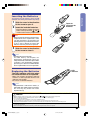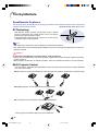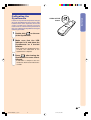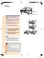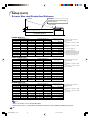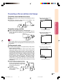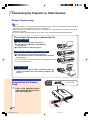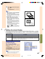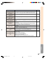
1
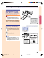
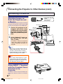
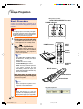
OPERATION MANUAL PG-M25X Introduction MODEL Setup and Connections Basic Operation Easy to Use Functions DIGITAL MULTIMEDIA PROJECTOR Appendix PG-M25X#E#Hyo1.p65 1 02.4.29, 3:01 PM IMPORTANT For your assistance in reporting the loss or theft of your Projector, please record the Serial Number located on the bottom of the projector and retain this information. Before recycling the packaging, please be sure that you have checked the contents of the carton thoroughly against the list of “Supplied accessories” on page 20. Model No.: PG-M25X Serial No.: This equipment complies with the requirements of Directives 89/336/EEC and 73/23/EEC as amended by 93/68/ EEC. Dieses Gerät entspricht den Anforderungen der EG-Richtlinien 89/336/EWG und 73/23/EWG mit Änderung 93/ 68/EWG. Ce matériel répond aux exigences contenues dans les directives 89/336/CEE et 73/23/CEE modifiées par la directive 93/68/CEE. Dit apparaat voldoet aan de eisen van de richtlijnen 89/336/EEG en 73/23/EEG, gewijzigd door 93/68/EEG. Dette udstyr overholder kravene i direktiv nr. 89/336/EEC og 73/23/EEC med tillæg nr. 93/68/EEC. Quest’ apparecchio è conforme ai requisiti delle direttive 89/336/EEC e 73/23/EEC, come emendata dalla direttiva 93/68/EEC. Η εγκατάσταση αυτή ανταποκρίνεται στις απαιτήσεις των οδηγιών της Ευρωπαϊκής Ενωσης 89/336/ ΕΟΚ και 73/23/ΕΟΚ, #πως οι κανονισµοί αυτοί συµπληρώθηκαν απ# την οδηγία 93/68/ΕΟΚ. Este equipamento obedece às exigências das directivas 89/336/CEE e 73/23/CEE, na sua versão corrigida pela directiva 93/68/CEE. Este aparato satisface las exigencias de las Directivas 89/336/CEE y 73/23/CEE, modificadas por medio de la 93/68/CEE. Denna utrustning uppfyller kraven enligt riktlinjerna 89/336/EEC och 73/23/EEC så som kompletteras av 93/68/ EEC. Dette produktet oppfyller betingelsene i direktivene 89/336/EEC og 73/23/EEC i endringen 93/68/EEC. Tämä laite täyttää direktiivien 89/336/EEC ja 73/23/EEC vaatimukset, joita on muutettu direktiivillä 93/68/EEC. GyroRemote This equipment complies with the requirements of Directive 1999/5/EC. GyroRemote-Fernbedienung Dieses Gerät entspricht den Anforderungen der EU-Richtlinie 1999/5/EG. GyroRemote Cet appareil est conforme aux exigences de la directive 1999/5/CE. GyroRemote Dit apparaat voldoet aan de eisen van de richtlijn 1999/5/EG. GyroFjernbetjening Dette udstyr overholder kravene i direktiv 1999/5/EF. GyroRemote Quest’ apparecchio è conforme ai requisiti delle direttiva 1999/5/CE. √ıÒÔÛÍÔÈ͸ TÁΘÂÈÒÈÛÙfiÒÈÔ « ÛıÛÍÂıfi ·ıÙfi ÂÌ·ÒÏÔÌflÊÂÙ·È Ï ÙÈÚ ··ÈÙfiÛÂÈÚ ÙÁÚ Ô‰Á„fl·Ú 1999/5/EK. GyroRemoto Este equipamento obedece às exigências da directiva 1999/5/CE. GyroRemote Este aparato satisface las exigencias de las Directiva 1999/5/CE. Gyrofjärrkontroll Denna utrustning uppfyller kraven enligt direktiv 1999/5/EC. GyroRemote Dette produktet oppfyller kravene i direktiv 1999/5/EC. Gyro-kauko-ohjain Tämä laite täyttää direktiivin 1999/5/EY vaatimukset. PG-M25X#E#Hyo2.p65 1 02.4.29, 3:03 PM PG-M25X#Ep00.p65 2 02.4.29, 3:05 PM SPECIAL NOTE FOR USERS IN THE U.K. The mains lead of this product is fitted with a non-rewireable (moulded) plug incorporating a 13A fuse. Should the fuse need to be replaced, a BSI or ASTA approved BS 1362 fuse marked or and of the same rating as above, which is also indicated on the pin face of the plug, must be used. Always refit the fuse cover after replacing the fuse. Never use the plug without the fuse cover fitted. In the unlikely event of the socket outlet in your home not being compatible with the plug supplied, cut off the mains plug and fit an appropriate type. DANGER: The fuse from the cut-off plug should be removed and the cut-off plug destroyed immediately and disposed of in a safe manner. Under no circumstances should the cut-off plug be inserted elsewhere into a 13A socket outlet, as a serious electric shock may occur. To fit an appropriate plug to the mains lead, follow the instructions below: IMPORTANT: The wires in the mains lead are coloured in accordance with the following code: Blue: Neutral Brown: Live As the colours of the wires in the mains lead of this product may not correspond with the coloured markings identifying the terminals in your plug, proceed as follows: • The wire which is coloured blue must be connected to the plug terminal which is marked N or coloured black. • The wire which is coloured brown must be connected to the plug terminal which is marked L or coloured red. Ensure that neither the brown nor the blue wire is connected to the earth terminal in your three-pin plug. Before replacing the plug cover make sure that: • If the new fitted plug contains a fuse, its value is the same as that removed from the cut-off plug. • The cord grip is clamped over the sheath of the mains lead, and not simply over the lead wires. IF YOU HAVE ANY DOUBT, CONSULT A QUALIFIED ELECTRICIAN. The supplied CD-ROM contains operation instructions in English, German, French, Swedish, Spanish, Italian, Dutch, Portuguese, Chinese and Korean. Carefully read through the operation instructions before operating the projector. Die mitgelieferte CD-ROM enthält Bedienungsanleitungen in Englisch, Deutsch, Französisch, Schwedisch, Spanisch, Italienisch, Niederländisch, Portugiesisch, Chinese, und Koreanisch. Bitte lesen Sie die Bedienungsanleitung vor der Verwendung des Projektors sorgfältig durch. Le CD-ROM fourni contient les instructions de fonctionnement en anglais, allemand, français, suédois, espagnol, italien, néerlandais, portugais, chinois et coréen. Veuillez lire attentivement ces instructions avant de faire fonctionner le projecteur. Den medföljande CD-ROM-skivan innehåller bruksanvisningar på engelska, tyska, franska, svenska, spanska, italienska, holländska, portugisiska, kinesiska och koreanska. Läs noga igenom bruksanvisningen innan projektorn tas i bruk. El CD-ROM suministrado contiene instrucciones de operación en inglés, alemán, francés, sueco, español, italiano, holandés, portugués, chino y coreano. Lea cuidadosamente las instrucciones de operación antes de utilizar el proyector. Il CD-ROM in dotazione contiene istruzioni per l’uso in inglese, tedesco, francese, svedese, spagnolo, italiano, olandese, portoghese, cinese e coreano. Leggere attentamente le istruzioni per l’uso prima di usare il proiettore. De meegeleverde CD-ROM bevat handleidingen in het Engels, Duits, Frans, Zweeds, Spaans, Italiaans, Nederlands, Portugees, Chinees en Koreaans. Lees de handleiding zorgvuldig door voor u de projector in gebruik neemt. O CD-ROM fornecido contém instruções de operação em Inglês, Alemão, Francês, Sueco, Espanhol, Italiano, Holandês, Português, Chinês e Coreano. Leia cuidadosamente todas as instruções de operação antes de operar o projetor. PG-M25X#Ep00.p65 1 02.4.29, 3:05 PM Before using the projector, please read this operation manual carefully. Introduction Introduction ENGLISH There are two important reasons for prompt warranty registration of your new SHARP Projector, using the REGISTRATION CARD packed with the projector. 1. WARRANTY This is to assure that you immediately receive the full benefit of the parts, service and labor warranty applicable to your purchase. 2. CONSUMER PRODUCT SAFETY ACT To ensure that you will promptly receive any safety notification of inspection, modification, or recall that SHARP may be required to give under the 1972 Consumer Product Safety Act, PLEASE READ CAREFULLY THE IMPORTANT “LIMITED WARRANTY” CLAUSE. U.S.A. ONLY WARNING: High brightness light source. Do not stare into the beam of light, or view directly. Be especially careful that children do not stare directly into the beam of light. WARNING: To reduce the risk of fire or electric shock, do not expose this product to rain or moisture. See bottom of actual set. CAUTION RISK OF ELECTRIC SHOCK. DO NOT REMOVE SCREWS EXCEPT SPECIFIED USER SERVICE SCREWS. CAUTION: TO REDUCE THE RISK OF ELECTRIC SHOCK, DO NOT REMOVE COVER. NO USER-SERVICEABLE PARTS EXCEPT LAMP UNIT. REFER SERVICING TO QUALIFIED SERVICE PERSONNEL. WARNING: The lightning flash with arrowhead symbol, within an equilateral triangle, is intended to alert the user to the presence of uninsulated “dangerous voltage” within the product’s enclosure that may be of sufficient magnitude to constitute a risk or electric shock to persons. The exclamation point within a triangle is intended to alert the user to the presence of important operating and maintenance (servicing) instructions in the literature accompanying the product. FCC Regulations state that any unauthorized changes or modifications to this equipment not expressly approved by the manufacturer could void the user’s authority to operate this equipment. U.S.A. ONLY INFORMATION This equipment has been tested and found to comply with the limits for a Class A digital device, pursuant to Part 15 of the FCC Rules. These limits are designed to provide reasonable protection against harmful interference when the equipment is operated in a commercial environment. This equipment generates, uses, and can radiate radio frequency energy and, if not installed and used in accordance with the operation manual, may cause harmful interference to radio communications. Operation of this equipment in a residential area is likely to cause harmful interference, in which case the user will be required to correct the interference at his own expense. U.S.A. ONLY The enclosed computer cable must be used with the device. The cable is provided to ensure that the device complies with FCC Class A verification. U.S.A. ONLY WARNING: This is a Class A product. In a domestic environment this product may cause radio interference in which case the user may be required to take adequate measures. -1 PG-M25X#E#p01_07.p65 1 02.4.29, 3:06 PM “Operation is subject to the following two conditions: (1) this device may not cause interference, and (2) this device must accept any interference, including interference that may cause undesired operation of the device”. CANADA ONLY For GyroRemote unit (RRMCG1631CESA) This device complies with part 15 of the FCC rules. Operation is subject to the following two conditions: (1) This device may not cause harmful interference, and (2) This device must accept any interference received, including interference that may cause undesired operation. This device operates in the frequency band of 49.82 to 49.90 MHz with RF output power of less than 30 MicroWatts EIRP (Effective Isotropic Radiated Power). Caution Any changes made to this device not expressly approved by the manufacturer could void the users right to operate this device. U.S.A. ONLY WARNING: The cooling fan in this projector continues to run for about 90 seconds after the projector is turned off. During normal operation, when turning the power off always use the POWER button on the projector or on the remote control. Ensure the cooling fan has stopped before disconnecting the power cord. DURING NORMAL OPERATION, NEVER TURN THE PROJECTOR OFF BY DISCONNECTING THE POWER CORD. FAILURE TO OBSERVE THIS WILL RESULT IN PREMATURE LAMP FAILURE. PRODUCT DISPOSAL This projector utilizes tin-lead solder, and a pressurized lamp containing a small amount of mercury. Disposal of these materials may be regulated due to environmental considerations. For disposal or recycling information, please contact your local authorities or, if you are located in the United States of America, the Electronic Industries Alliance: www.eiae.org . Caution Concerning the Lamp Replacement See “Replacing the Lamp” on page 111. LAMP REPLACEMENT CAUTION BEFORE REMOVING THE SCREW, DISCONNECT POWER CORD. HOT SURFACE INSIDE. ALLOW 1 HOUR TO COOL BEFORE REPLACING THE LAMP. REPLACE WITH SAME SHARP LAMP UNIT TYPE BQC-PGM20X//1 ONLY. UV RADIATION : CAN CAUSE EYE DAMAGE. TURN OFF LAMP BEFORE SERVICING. MEDIUM PRESSURE LAMP : RISK OF EXPLOSION. POTENTIAL HAZARD OF GLASS PARTICLES IF LAMP HAS RUPTURED. HANDLE WITH CARE. SEE OPERATION MANUAL. PRECAUTIONS A OBSERVER LORS DU REMPLACEMENT DE LA LAMPE. DEBRANCHER LE CORDON D’ALIMENTATION AVANT DE RETIRER LES VIS. L’INTERIEUR DU BOITIER ETANT EXTREMEMENT CHAUD, ATTENDRE 1 HEURE AVANT DE PROCEDER AU REMPLACEMENT DE LA LAMPE. NE REMPLACER QUE PAR UNE LAMPE SHARP DE TYPE BQC-PGM20X//1. RAYONS ULTRAVIOLETS : PEUVENT ENDOMMAGER LES YEUX. ETEINDRE LA LAMPE AVANT DE PROCEDER A L’ENTRETIEN. LAMPE A MOYENNE PRESSION : RISQUE D’EXPLOSION. DANGER POTENTIEL DE PARTICULES DE VERRE EN CAS D’ECLATEMENT DE LA LAMPE A MANIPULER AVEC PRECAUTION, SE REPORTER AU MODE D’EMPLOI. -2 PG-M25X#E#p01_07.p65 2 02.4.29, 3:06 PM Outstanding Features Introduction 1. Image Quality • Superior image quality with Fujinon™ optical lens system. • Newly developed DDR (Double Data Rate) chip eliminates Color Breaking phenomena common with previous generation DLP™ projectors. • Newly developed 12° DMD™ chip provides significantly improved optical efficiency and excellent contrast ratio. 2. Light, Compact, and Unique Slim Design • A new optical engine creates a unique slim design and compact size (4.2 liters, 5.8 lbs. (2.6 kg)). 3. Superior PC Compatibility • Supports a refresh rate (vertical frequency) of up to 200 Hz and a wide range of synchronous signals. • Using Advanced Compression Technology, computer screens of UXGA (1,600 # 1,200) resolution can be displayed with minimal distortion. 4. Advanced Computer & Video lntegrated Composer Technology • Realizes vivid images using the latest high image quality circuitry. • New I/P conversion algorithm enhances the performance of the motion detect I/P conversion. Extensive improvements on the jagged edges or slanted lines in moving images. • Contrast Control Dynamic Gamma Improved contrast and natural color gradation by minimizing hue change. • Color Management Function Supports sRGB (color management). • Noise Reduction Allows for a clear image even with noisy source signals. • New Edge Up-Scaling Reduces jaggies and flickering when up-scaling edges of slanted lines, enabling sharper quality images. -3 PG-M25X#E#p01_07.p65 3 02.4.29, 3:06 PM 6. Built-in PCMCIA card slot (Type II) • Wireless presentations using a wireless LAN PC card. Supports the global wireless LAN standard, IEEE802.11b. This wireless LAN PC card complies with IEEE802.11b wireless LAN standards. Computers with built-in wireless LAN PC cards that support this standard allow for wireless connections. Note • A wireless connection with all IEEE802.11b compliant computers is not guaranteed. The projector or computer can be placed anywhere you want! You can expand your presentation efficiency through a wireless connection, for example, by projecting computer images through a projector installed on the ceiling. You can display images from a computer selected from a group of computers. Effective presentations can now be realized without having to reconnect data cables all the time. • PC-less presentations using a memory card. Just by inserting an IC media (a memory card) such as CompactFlash in the projecter using a PCMCIA card (Type II) adapter, you can make presentations or auto demonstrations without using a computer. Note • For wireless presentations using the wireless LAN PC card, as well as PC-less presentations using memory cards, please refer to the Wireless Reality operation manual. 7. GyroRemote • Using the Gyro function, you can realize more effective and advanced presentations. • The crisp screen pointer gives your presentations a more intuitive touch. • Using the multi-directional wireless remote control, your transmission range can be expanded, as well as perform the same operations as a USB mouse on a computer. -4 PG-M25X#E#p01_07.p65 4 02.4.29, 3:06 PM Contents Outstanding Features ......................................... 3 Contents ............................................................... 5 IMPORTANT SAFEGUARDS ............................... 8 How to Access the PDF Operation Manuals (Windows, Macintosh) ................................. 13 Part Names ........................................................ 14 Projector (Front and Top View) ................................ 14 Projector (Side View) .............................................. 15 GyroRemote ............................................................. 16 Inserting the Batteries ............................................. 17 Replacing the Batteries ........................................... 17 The GyroRemote ............................................... 18 GyroRemote Features .............................................. 18 Calibrating the GyroRemote ................................... 19 Accessories ....................................................... 20 Introduction Introduction Gesture Operation (Selecting OSD Menus, Operating Presentation Tools) .................................................................... 40 Function Assign ....................................................... 41 GyroRemote Channel Setting .................................. 42 Registering the GyroRemote in the Projector .......... 42 Registering Multiple GyroRemotes in One Projector43 Using the Presentation Tools ........................... 44 Using the Pointer .................................................... 44 Using the Stamp Function ....................................... 45 Using the Line Function ........................................... 46 Using the Wireless Presentation Function of the GyroRemote ...................................... 47 Connecting the Computer and the Projector ................................. 47 Using as a Wireless Mouse ..................................... 48 Connecting the GyroRemote with a Cable ............. 48 Turning Off the GyroRemote ................................... 49 Using the Menu Screen .................................... 50 Setup and Connections Setup .................................................................. 22 Using the Adjustment Feet ..................................... 22 Setting up the Screen .............................................. 23 Screen Size and Projection Distance ...................... 24 Projecting a Reversed/Inverted Image ................... 25 Connecting the Projector to Other Devices .... 26 Before Connecting .................................................. 26 Connecting the Power Cord ................................... 26 Connecting the Projector to a Computer ......... 27 Connecting to Video Equipment ...................... 29 Installing / Removing the PC Card ................... 31 Connecting to a Monitor .................................. 32 Basic Operation Image Projection ............................................... 34 Basic Procedure ...................................................... 34 Selecting the On-screen Display Language ........... 37 Adjusting the Lens .................................................. 37 Correcting the Trapezoidal Distortion (Keystone Correction) ................................. 38 Menu Selections on the Projector (Adjustments) .... 50 Menu Selections on the projector (Settings) ........... 52 Using the GyroRemote to Navigate the On-screen Menu (Adjustments) ............................................. 54 Using the GyroRemote to Navigate the On-screen Menu (Settings) .................................................... 55 Menu Bar Items ................................................. 56 Adjusting the Picture ........................................ 59 Adjusting Image Preferences .................................. 59 Selecting the Signal Type ....................................... 59 Progressive Mode .................................................... 60 Adjusting Computer Images ............................ 61 When Auto Sync is OFF ........................................... 61 Saving Adjustment Settings ..................................... 61 Selecting Adjustment Settings ................................ 62 Special Mode Settings ............................................ 62 Checking the Input Signal ....................................... 63 Auto Sync Adjustment ............................................. 63 Auto Sync Display Function ................................... 64 Easy to Use Functions Using the Network ............................................. 66 Correcting the Trapezoidal Distortion ...................... 38 Before setting the network ....................................... 66 Using the GyroRemote ..................................... 40 Using a Wireless LAN PC Card ........................ 68 Before Using the GyroRemote ................................. 40 Installing a Wireless LAN PC Card .......................... 68 Ejecting the Card .................................................... 68 -5 PG-M25X#E#p01_07.p65 5 02.4.29, 3:06 PM Network Settings ............................................... 69 Setting Up a Projector Name ................................... 69 Setting the IP Address ............................................. 70 Setting the Wireless Channel ................................... 71 Setting the SSID ...................................................... 72 Setting the DHCP Server ......................................... 73 Resetting the Network Settings .............................. 74 Capturing the Image .............................................. 94 Deleting the Captured Image .................................. 94 Setting a Background Image ............................ 95 Selecting a Background Image .............................. 95 Using an RGB Monitor Loop-out Adaptor ...... 96 Using an RGB Monitor Loop-out Adaptor ............... 96 Displaying the Lamp Usage Time .................... 96 Wireless LAN PC card: Troubleshooting ......... 74 Confirming the Lamp Usage Time .......................... 96 Using a Memory Card ....................................... 75 Displaying the Break Timer .............................. 97 Displaying of the Contents in the Card as an Index 75 Ejecting the Card .................................................... 75 Setting the Thumbnail Display ................................. 76 Setting Lists ............................................................. 77 Displaying and Setting the Break Timer ................. 97 To cancel the break time ......................................... 97 Memory Card Settings ...................................... 78 Setting Files ............................................................. 78 Setting the Display Order of Files ............................ 78 Setting the Display Format of the Index Mode ........ 79 Using Autorun ......................................................... 79 Setting the Display Interval for Image Files ............. 80 Displaying a Still Image .................................... 81 Storing an Image in Still Image Format ................... 81 Selecting the Picture Display Mode ................ 82 Switching the Picture Display Using Different Input Signals .................................................................. 82 Enlarging a Specific Portion of an Image ....... 84 Displaying an Enlarged Portion of an Image ........... 84 Gamma Correction Function ............................ 86 Adjusting Gamma Correction .................................. 86 Reversing/Inverting Projected Images ............ 98 Setting the Projection Mode ................................... 98 Locking the Operation Buttons on the Projector ........................................... 99 Setting up the Keylock ............................................ 99 Canceling the Keylock Setting ................................ 99 Setting up a Password .................................... 100 Entering the Password ........................................... 100 Changing the Password ....................................... 101 If You Forget Your Password ................................. 101 Setting the Anti-Theft...................................... 102 Entering the Keycode ............................................ 102 Changing the Keycode ......................................... 104 Initializing the Settings ................................... 105 Returning to the Default Settings .......................... 105 Displaying the Adjustment Settings .............. 106 Overview of ALL Menu Settings ............................ 106 Selecting the Power Save Mode ...................... 87 Setting the Power Save Mode ................................. 87 Automatic Power Shutoff Function .......................... 87 Displaying Dual Pictures (Pict in Pict) ............ 88 Displaying the Inset Picture ..................................... 88 Setting On-screen Display ............................... 89 Turning Off the On-screen Display .......................... 89 Activating the sRGB Color Management Function ................................ 90 Setting the Color Management Function (sRGB) .... 90 Auto Search Function ....................................... 91 Using Auto Search .................................................. 91 Video Digital Noise Reduction (DNR) System 92 Reducing Image Noise ............................................ 92 Setting the Video Signal ................................... 93 Selecting a Startup Image ................................ 93 Selecting a Startup Image ....................................... 93 Saving Projected Images .................................. 94 Appendix Carrying the Projector .................................... 108 How to Use the Carrying Case .............................. 108 Maintenance .................................................... 109 Maintenance Indicators .................................. 110 Regarding the Lamp ....................................... 111 Lamp .................................................................... 111 Caution Concerning the Lamp .............................. 111 Replacing the Lamp .............................................. 111 Removing and Installing the Lamp Unit ............... 112 Resetting the Lamp Timer ..................................... 113 Connecting Pin Assignments ........................ 114 Computer Compatibility Chart ....................... 115 Troubleshooting .............................................. 116 For SHARP Assistance ................................... 118 Specifications .................................................. 119 -6 PG-M25X#E#p01_07.p65 6 02.4.29, 3:06 PM Introduction Wireless LAN PC Card Specification ............ 120 Usable Cards and Their Capacity .................. 121 Dimensions ...................................................... 122 Glossary ........................................................... 123 Index ................................................................. 125 -7 PG-M25X#E#p01_07.p65 7 02.4.29, 3:06 PM IMPORTANT SAFEGUARDS CAUTION: Please read all of these instructions before you operate this product and save these instructions for later use. Electrical energy can perform many useful functions. This product has been engineered and manufactured to assure your personal safety. BUT IMPROPER USE CAN RESULT IN POTENTIAL ELECTRICAL SHOCK OR FIRE HAZARDS. In order not to defeat the safeguards incorporated in this product, observe the following basic rules for its installation, use and servicing. 11. Power Sources 1. Read Instructions All the safety and operating instructions should be read before the product is operated. 2. Retain Instructions The safety and operating instructions should be retained for future reference. 3. Heed Warnings All warnings on the product and in the operating instructions should be adhered to. 4. Follow Instructions All operating and use instructions should be followed. 5. Cleaning Unplug this product from the wall outlet before cleaning. Do not use liquid cleaners or aerosol cleaners. Use a damp cloth for cleaning. 6. Attachments Do not use attachments not recommended by the product manufacturer as they may cause hazards. 7. Water and Moisture Do not use this product near water–for example, near a bath tub, wash bowl, kitchen sink, or laundry tub; in a wet basement; or near a swimming pool; and the like. 8. Accessories Do not place this product on an unstable cart, stand, tripod, bracket, or table. The product may fall, causing serious injury to a child or adult, and serious damage to the product. Use only with a cart, stand, tripod, bracket, or table recommended by the manufacturer, or sold with the product. Any mounting of the product should follow the manufacturer’s instructions, and should use a mounting accessory recommended by the manufacturer. This product should be operated only from the type of power source indicated on the marking label. If you are not sure of the type of power supply to your home, consult your product dealer or local power company. For products intended to operate from battery power, or other sources, refer to the operating instructions. 12. Grounding or Polarization This product is provided with one of the following types of plugs. If the plug should fail to fit into the power outlet, please contact your electrician. Do not defeat the safety purpose of the plug. a. Two-wire type (mains) plug. b. Three-wire grounding type (mains) plug with a grounding terminal. This plug will only fit into a grounding type power outlet. 13. Power-Cord Protection Power-supply cords should be routed so that they are not likely to be walked on or pinched by items placed upon or against them, paying particular attention to cords at plugs, convenience receptacles, and the point where they exit from the product. 14. Lightning For added protection for this product during a lightning storm, or when it is left unattended and unused for long periods of time, unplug it from the wall outlet and disconnect the cable system. This will prevent damage to the product due to lightning and power-line surges. 15. Overloading Do not overload wall outlets, extension cords, or integral convenience receptacles as this can result in a risk of fire or electric shock. 16. Object and Liquid Entry 9. Transportation A product and cart combination should be moved with care. Quick stops, excessive force, and uneven surfaces may cause the product and cart combination to overturn. 10.Ventilation Slots and openings in the cabinet are provided for ventilation to ensure reliable operation of the product and to protect it from overheating, and these openings must not be blocked or covered. The openings should never be blocked by placing the product on a bed, sofa, rug, or other similar surface. This product should not be placed in a built-in installation such as a bookcase or rack unless proper ventilation is provided or the manufacturer’s instructions have been adhered to. Never push objects of any kind into this product through openings as they may touch dangerous voltage points or short-out parts that could result in a fire or electric shock. Never spill liquid of any kind on the product. 17. Servicing Do not attempt to service this product yourself as opening or removing covers may expose you to dangerous voltage or other hazards. Refer all servicing to qualified service personnel. -8 PG-M25X#E#p08_20_a.p65 8 02.4.29, 4:55 PM Unplug this product from the wall outlet and refer servicing to qualified service personnel under the following conditions: a. When the power-supply cord or plug is damaged. b. If liquid has been spilled, or objects have fallen into the product. c. If the product has been exposed to rain or water. d. If the product does not operate normally by following the operating instructions. Adjust only those controls that are covered by the operating instructions, as an improper adjustment of other controls may result in damage and will often require extensive work by a qualified technician to restore the product to normal operation. e. If the product has been dropped or damaged in any way. f. When the product exhibits a distinct change in performance, this indicates a need for service. Introduction 18. Damage Requiring Service 19. Replacement Parts When replacement parts are required, be sure the service technician has used replacement parts specified by the manufacturer or have the same characteristics as the original part. Unauthorized substitutions may result in fire, electric shock, or other hazards. 20. Safety Check Upon completion of any service or repairs to this product, ask the service technician to perform safety checks to determine that the product is in proper operating condition. 21. Wall or Ceiling Mounting This product should be mounted to a wall or ceiling only as recommended by the manufacturer. 22. Heat This product should be situated away from heat sources such as radiators, heat registers, stoves, or other products (including amplifiers) that produce heat. -9 PG-M25X#E#p08_20_a.p65 9 02.4.29, 4:55 PM IMPORTANT SAFEGUARDS (cont.) INTELLECTUAL PROPERTY RIGHTS IMPORTANT READ BEFORE USING THE PRODUCT • You have acquired a product that includes software licensed to SHARP Corporation by Lineo, Inc. (“Lineo”). The Software is protected by copyright laws, international copyright treaties, and other intellectual property laws and treaties. Lineo and its suppliers retain all ownership of, and intellectual property rights in (including copyright), the Software components and all copies thereof, provided however, that certain components of the Software are components licensed under the GNU General Public License (version 2), which Lineo supports. You may obtain a copy of the GNU General Public License at http://www.fsf.org/ copyleft/gpl.html. Lineo will provide source code for any of the components of the Software licensed under the GNU General Public License. To obtain such source code, send email to [email protected]. • OS: Embedix (Embedded Linux) Embedix (TM) is a registered trademark of U.S.A. LINEO, Inc. • DLP™ (Digital Light Processing) and DMD™ (Digital Micromirror Device) are trademarks of Texas Instruments, Inc. • Microsoft and Windows are registered trademarks of Microsoft Corporation, in the United States and/or other countries. • PC/AT is a registered trademark of International Business Machines Corporation in the United States. • Adobe Acrobat is a trademark of Adobe Systems Incorporated. • Macintosh is a registered trademark of Apple Computer, Inc. in the United States and/or other countries. • All other company or product names are trademarks or registered trademarks of their respective companies. • Some IC chips in this product include confidential and/or trade secret property belonging to Texas Instruments. Therefore you may not copy, modify, adapt, translate, distribute, reverse engineer, reverse assemble or discompile the contents thereof. -10 PG-M25X#E#p08_20_a.p65 10 02.4.29, 4:55 PM Caution concerning the lamp unit ■ Potential hazard of glass particles if lamp ruptures. In case of lamp rupture, contact your nearest Sharp Authorized Projector Dealer or Service Center for a replacement. See “Replacing the Lamp” on page 71. Do not subject the projector to hard impact and/or vibration. ■ Take care with the lens so as not to hit or damage the surface of the lens. Rest your eyes occasionally. CAUTION PRECAUCI N PR CAUTION BQC-PGM20X//1 Cautions concerning the setup of the projector ■ For minimal servicing and to maintain high image quality, SHARP recommends that this projector be installed in an area free from humidity, dust and cigarette smoke. When the projector is subjected to these environments, the lens must be cleaned more often. As long as the projector is regularly cleaned, use in these environments will not reduce the overall operation life of the unit. Internal cleaning should only be performed by a Sharp Authorized Projector Dealer or Service Center. ■ Continuously watching the screen for long hours will make your eyes tired. Be sure to rest your eyes sometimes. Avoid locations with high or low temperature. ■ The operating temperature for the projector is from 41°F to 95°F (+5°C to +35°C) ■ The storage temperature for the projector is from –4°F to 140°F (–20°C to +60°C) Do not block the exhaust and intake vents. ■ Position the screen so that it is not in direct sunlight or room light. Light falling directly on the screen washes out the colors, making viewing difficult. Close the curtains and dim the lights when setting up the screen in a sunny or bright room. ■ Allow at least 11.8 inches (30 cm) of space between the exhaust vent and the nearest wall or obstruction. ■ Be sure that the intake vent and the exhaust vent are not obstructed. ■ If the cooling fan becomes obstructed, a protection circuit will automatically turn off the projector. This does not indicate a malfunction. Remove the projector power cord from the wall outlet and wait at least 10 minutes. Place the projector where the intake and exhaust vents are not blocked, plug the power cord back in and turn on the projector. This will return the projector to the normal operating condition. The projector may safely be tilted to a maximum angle of 10 degrees. Cautions regarding the transportation of the projector Do not set up the projector in places exposed to direct sunlight or bright light. ■ Placement should be within ±10 degrees. 10 10 ■ When transporting the projector, be sure not to subject it to hard impact and/or vibration, as this can result in damage. Take extra caution with the lens. Before moving the projector, be sure to retract the antenna and the card eject button. Also, be sure to unplug the power cord from the wall outlet, disconnect any other cables connected to it and retract the antenna. -11 PG-M25X#E#p08_20_a.p65 11 02.4.29, 4:56 PM Introduction Be sure to read the following safeguards when setting up your projector. IMPORTANT SAFEGUARDS (cont.) Other connected equipment ■ When connecting a computer or other audiovisual equipment to the projector, make the connections AFTER turning off the projector and the equipment to be connected. ■ Please read the operation manuals of the projector and the equipment to be connected for instructions on how to make the connections. Using the projector in other countries ■ The power supply voltage and the shape of the plug may vary depending on the region or country you are using the projector in. When using the projector overseas, be sure to use the appropriate power cord for the country you are in. Temperature monitor function ■ If the projector starts to overheat due to setup problems or blockage of the air vents, “ ” and “ ” will blink in the lower left corner of the picture. If the temperature continues to rise, the lamp will turn off, the TEMPERATURE WARNING indicator on the projector will blink, and after a 90-second cooling-off period the power will shut off. Refer to “Maintenance Indicators” on page 70 for details. Info • The cooling fan regulates the internal temperature, and its performance is automatically controlled. The sound of the fan may change during projector operation due to changes in the fan speed. This does not indicate malfunction. • Do not unplug the power cord during projection or cooling fan operation. This can create damage due to the rise in internal temperature, as the cooling fan also stops. -12 PG-M25X#E#p08_20_a.p65 12 02.4.29, 4:56 PM PDF operation manuals in several languages are included in the CD-ROM, so that you can work with the projector, even if you do not have this manual on hand. To utilize these manuals, you need to install Adobe Acrobat Reader on your PC (Windows or Macintosh). If you have not installed Acrobat Reader yet, you can install it from the CD-ROM. To Install Acrobat Reader from the CD-ROM For Windows: 1 Insert the CD-ROM in the CD-ROM drive. 2 Double click the “My Computer” icon. 3 Double click the “CD-ROM” drive icon. 4 Double click the “acrobat” folder. 5 Double click the “windows” folder. 6 Double click the language (name of the folder) that you want to view. 7 Double click the installation program and follow the instructions on the screen. For Macintosh: 1 Insert the CD-ROM in the CD-ROM drive. 2 Double click the “CD-ROM” icon. 3 Double click the “acrobat” icon. 4 Double click the language (name of the folder) that you want to view. 5 Double click the desired installation program and follow the instructions on the screen. For other operating systems: Please download Acrobat Reader from the Internet (http://www.adobe.com) For other languages: If you prefer using Acrobat Reader for languages other than those included in the CD-ROM, please download the appropriate version from the Internet. Accessing the PDF Manuals For Windows: 1 Insert the CD-ROM in the CD-ROM drive. 2 Double click the “My Computer” icon. 3 Double click the “CD-ROM” drive. 4 Double click the “manuals” folder. 5 Double click the language (name of the folder) that you want to view. 6 Double click the “m25x” pdf file to access the projector manuals. Double click the “soft” pdf file to access the Wireless Reality. Double click the “WC11b” pdf file to access the Wireless LAN PC Card manual. For Macintosh: 1 Insert the CD-ROM in the CD-ROM drive. 2 Double click the “CD-ROM” icon. 3 Double click the “manuals” folder. 4 Double click the language (name of folder) that you want to view. 5 Double click the “m25x” pdf file to access the projector manuals. Note • If the desired pdf file cannot be opened by double clicking the mouse, start Acrobat Reader first, then specify the desired file using the “File”, “Open” menu. • See the “readme.txt” file on the CD-ROM for important information not included in this operation manual. -13 PG-M25X#E#p08_20_a.p65 13 02.4.29, 4:56 PM Introduction How to Access the PDF Operation Manuals (Windows, Macintosh) Part Names Numbers in refer to the main pages in this Operation Manual where the topic is explained. Projector (Front and Top View) 110 TEMPERATURE 110 LAMP replacement indicator warning indicator Illuminates in green normally. Replace the lamp when the indicator illuminates in red. POWER indicator Illuminates in green normally. When the internal temperature rises, this indicator will illuminate in red. 110 Illuminates in red, when the projector is in standby. When the power is turned on, this indicator will illuminate in green. 35 For switching input mode 1, 2, 3 or 4. 50 34 POWER button MENU button For displaying adjustment and setting screens. Turns the power on or off. 38 LENS button INPUT button 35 VOLUME buttons For adjusting the speaker sound level. For adjusting Keystone or Digital Shift setting. 50 Adjustment buttons "'\ | ("'\ |) 51 UNDO button For undoing an operation or returning to the default settings. For selecting menu items. ENTER button 50 63 For setting items selected or adjusted on the menu. For automatically adjusting images when connected to a computer. 35 AV MUTE button AUTO SYNC button For temporarily turning off the sound and picture. GyroRemote Antenna 40 Zoom knob 37 37 Focus ring 14 Terminal cover 35 Speaker 18 Remote control sensor Foot releases/Adjustment 22 feet For adjusting the projector’s height. Attaching the terminal cover Attach the terminal cover by placing it on the side panel of the projector and pressing it into place, as shown in the illustration. -14 PG-M25X#E#p08_20_a.p65 14 02.4.29, 4:56 PM Introduction Projector (Side View) 47 USB terminal For connecting a computer using a USB cable. 27 INPUT 1 terminal Shared audio terminal for INPUT 1, INPUT 2, INPUT 3 and INPUT 4. 27 Port for DVI digital, computer RGB, and COMPONENT signals. INPUT AUDIO terminal 30 INPUT 3 terminal For connecting video equipment. 30 INPUT 2 terminal Terminal for connecting video equipment with an S-VIDEO terminal. AC socket 26 Exhaust vent 11 Kensington Security Standard connector 15 48 Wired remote contorl input terminal (ø3.5 mm minijack) 31 INPUT 4 terminal For inserting a wireless LAN PC card or a memory card. Using the Kensington Lock • This projector has a Kensington Security Standard connector for use with a Kensington MicroSaver Security System. Refer to the information that came with the system for instructions on how to use it to secure the projector. Attaching the lens cap After putting the lens cap strap on the lens cap, pass the other end of the strap through the hole under the projector, next to the lens, as shown in the illustration. Bottom View -15 PG-M25X#E#p08_20_a.p65 15 02.4.29, 4:56 PM Part Names (cont.) GyroRemote Front Function 1 / 2 buttons For specifying the button assignments for Function 1 and Function 2 INPUT button For switching between inputs 1,2,3 and 4. L-CLICK/ ENTER button For entering menu items or to perform a left click when using the wireless mouse. POWER button 42 LED indicator 44 POINTER button 48 R-CLICK / UNDO button 54 MENU button 35 VOLUME buttons 40 35 48 49 For turning the power on or off. LENS button For adjusting Keystone or Digital Shift setting. Function 3 / 4 buttons For registering the GyroRemote in the projector. 42 For undoing an operation or to perform a right click when using the wireless mouse. For displaying adjustment and setting screens. 41 ASSIGN button 42 RF CH+ button 40 TEACH (OK) button Holding this button down displays a pointer on the screen. For adjusting the speaker sound level. 38 For specifying the button assignments for Function 3 and Function 4 Lights up when the GyroRemote is in motion. Switches the button assignment function group. For checking the current RF channel as well as switching the channel. Rear Bottom 48 Wired remote 44 terminal (ø2.5 mm minijack) GYRO ACTIVE For moving the Gyro function for actions such as moving tool icons (such as stamp), selecting menus in the OSD, or moving the cursor using the wireless mouse. WIRE R/C JACK Gyration U.S. Patents 5698784, 5825350, 5898421 -16 PG-M25X#E#p08_20_a.p65 16 02.4.29, 4:56 PM Inserting the Batteries Introduction The batteries (four R03 batteries (“AAA” size, UM/ SUM-4, HP-16 or similar)) are included in the package. 1 Slide the cover in the direction of the arrow to open it. 2 Insert the included batteries. Tapes for removing the batteries • Insert the batteries making sure the poand larities correctly match the marks inside the battery compartment. Info • When inserting the batteries into the battery compartment of the GyroRemote, make sure that the batteries are placed over the pullstring for the easy removal in the feature. If not, it may be difficult to remove old batteries when they have to be replaced. 3 Slide the cover in the direction of the arrow to close it. Note • GyroRemote Sleep Function To avoid batter y consumption, the GyroRemote automatically enters the Sleep mode if not action takes place within 5 minutes. If the GyroRemote cannot be operated, press once the POWER button on the GyroRemote to resume operation. LED indicator Replacing the Batteries The LED indicator will blink when the batteries need to be replaced. • Make sure to replace the batteries with new batteries as soon as possible when the LED indicator starts to blink. • Be sure to use alkaline batteries. Note • If GyroRemote is idle for five minutes, it will go into sleep mode to conserve battery life. Pressing any button will make GyroRemote up. Incorrect use of the batteries may cause them to leak or explode. Please follow the precautions below. Caution • Insert the batteries making sure the polarities correctly match the and marks inside the battery compartment. • Batteries of different types have different properties, therefore do not mix batteries of different types. • Do not mix new and old batteries. This may shorten the life of new batteries or may cause old batteries to leak. • Remove the batteries from the remote control once they have run out, as leaving them can cause them to leak. Battery fluid from leaked batteries is harmful to your skin, therefore be sure to first wipe them and then remove them using a cloth. • The batteries included with this projector may be exhausteol over a short period, depending on how they are kept. Be sure to replace them as soon as possible with new batteries. • Remove the batteries from the remote control if you will not be using the remote control for a long time. -17 PG-M25X#E#p08_20_a.p65 17 02.4.29, 4:56 PM The GyroRemote GyroRemote Features This projector uses the GyroRemote technology, that allows for the following features when compared to ordinary infrared remote controls. Operation Range: Area up to a 15 m RF Technology With ordinary remote controls, the operation range is limited because of directivity; they cannot operate if there are objects between the projector and the remote. The GyroRemote can operate up to a range of 15 m (49.2 feet) by sending RF signals to the projector. Note • The control range measured is with the projector’s antenna fully extended. • The control range under actual operating conditions may be less than optimum depending on where the projector is placed. Caution Do not use the GyroRemote in restricted places, such as hospitals. • Signals from the GyroRemote may affect electronic equipment or medical electronic equipment, thereby causing accidents. • When using the GyroRemote in medical institutions, make sure to follow the directives of each institution. Multi-Projector Control This projector has a GyroRemote identification function that makes possible to perform various operations such as the ones below. ■ No interference even if other projectors of the same type are within the GyroRemote’s operating range. ■ Multiple projectors can be operated with one GyroRemote. ■ One projector can be operated using multiple GyroRemotes. • Refer to page 40 for details about using the GyroRemote. -18 PG-M25X#E#p08_20_a.p65 18 02.4.29, 4:56 PM If there are any extreme temperature changes when the GyroRemote is being used or after batteries have been replaced, the mouse cursor or pointer may continue to move by itself even if no action has been performed. In this case, calibrate the GyroRemote using the following procedure. 1 Double click on the rear of the GyroRemote. 2 Make sure that the LED indicator is lit, and place the GyroRemote on a leveled location. Introduction Calibrating the GyroRemote GYRO ACTIVE button • After leaving the GyroRemote for 6 seconds, the calibration of the GyroRemote is complete. 3 Press , after leaving the GyroRemote for more than 6 seconds. • Calibration is complete after the remote has been left for more than 6 seconds. -19 PG-M25X#E#p08_20_a.p65 19 02.4.29, 4:56 PM Accessories Supplied accessories GyroRemote (1) For U.S., Canada, etc. RRMCG1631CESA (2) For Europe, Australia, Oceania and Asia RRMCG1653CESA Four R03 batteries (“AAA” size, UM/SUM-4, HP-16 or similar) Power cord (6' (1.8m)) (1) (2) For U.S., Canada, etc. QACCDA007WJPZ (4) (3) For Europe, except U.K. QACCV4002CEZZ For Australia, New Zealand and Oceania QACCL3022CEZZ For U.K., Hong Kong and Singapore QACCB5024CENA Note • Depending on the region, projectors only ship with one power cord (see above). Use the power cord that corresponds to the wall outlet in your country. DVI to 15-pin D-sub cable (6' (1.8m)) QCNWGA010WJZZ USB cable (6' (1.8 m)) QCNWG0001WJPZ Carrying case GCASN0005CESA Two Wireless LAN PC cards AN-WC11B (RUNTKA025WJZZ) CD-ROM UDSKA001WJZZ Lens cap strap UBNDT0013CEZZ Lens cap (attached) CCAPHA001WJ01 Terminal cover (attached) GCOVD0103CESA Operation manual (this manual) Quick reference guides Wireless Reality operation manual Wireless LAN PC card precautions Optional accessories DVI cable (9'10'' (3.0 m)) AN-C3DV 3 RCA to 15-pin D-sub cable (9'10'' (3.0 m)) AN-C3CP Computer RGB cable (32'10'' (10.0 m)) AN-C10BM <for IBM-PC, PC9821, and PC98NX systems> AN-C10PC <for PC98 systems (Except PC9821 and PC98NX systems)> 5 BNC to 15-pin D-sub cable (9'10'' (3.0 m)) AN-C3BN RGB monitor loop-out adaptor (7.9'' (20 cm)) AN-A1MY DVI to 15-pin D-sub adaptor (7.9'' (20 cm)) AN-A1DV • If you cannot connect after changing computer ports, be sure to check you computer’s specifications. If you are still having difficulty connecting, a conversion connector (commercially available) may be necessary. Wireless LAN PC card AN-WC11B Note • All cables may not be available in all regions. Please check with your nearest Sharp Authorized Projector Dealer or Service Center. -20 PG-M25X#E#p08_20_a.p65 20 02.4.29, 4:56 PM Setup and Connections Setup and Connections PG-M25X#E#p21_32.p65 21 02.4.29, 3:09 PM Setup Foot releases Adjustment feet Using the Adjustment Feet The height of the projector can be adjusted using the adjustment feet when the surface of the projector is placed on is uneven or when the screen is slanted. The projection of the image can be made higher by adjusting the projector when it is in a location lower than the screen. 1 Press the foot releases. 2 Lift the projector to adjust its height and remove your hands from the foot releases. 3 Rotate the adjustment feet to make minor changes. Up Down Note • When returning the projector to its original position, hold the projector firmly, press the foot releases and then lower it. • The projector is adjustable up to approximately 5.5 degrees from the standard position. Info • Do not press the foot releases when the feet are extended without firmly holding the projector. • Do not hold the lens when lifting or lowering the projector. • When lowering the projector, be careful not to get your fingers caught in the area between the adjustment feet and the projector. -22 PG-M25X#E#p21_32.p65 22 02.4.29, 3:09 PM Setting up the Screen Position the projector perpendicular to the screen with all feet flat and level to achieve an optimal image. Note Standard Setup (Front Projection) ■ Place the projector at the required distance from the screen according to the desired picture size. (See page 24.) Example of Standard Setup • The distance from the screen to the projec- Side View tor may vary depending on the size of the screen. P.24 • The default setting can be used, when plac- 90° Audience ing the projector in front of the screen. If the projected image is reversed or inverted, readjust the setting to “Front” in “PRJ Mode”. P.98 • Place the projector so that an imaginary Top View horizontal line that passes through the center of the lens is perpendicular to the screen. 90° -23 PG-M25X#E#p21_32.p65 23 02.4.29, 3:09 PM Setup and Connections • The projector lens should be centered in the middle of the screen. If the horizontal line passing through the lens center is not perpendicular to the screen, the image will be distorted, making viewing difficult. • For optimal image, position the screen so that it is not in direct sunlight or room light. Light falling directly on the screen washes out the colors, making viewing difficult. Close the curtains and dim the lights when setting up the screen in a sunny or bright room. • A polarizing screen cannot be used with this projector. Setup (cont.) Screen Size and Projection Distance Screen Base line: Horizontal line passing through the lens center. Lens center 90° H L:Projection distance NORMAL Mode (4:3) Picture (Screen) size Diag. (X) Width Projection distance (L) Height Maximum (L1) Minimum (L2) – Distance from the lens center to the bottom of the image (H) 300" (762 cm) 240" (610 cm) 180" (457 cm) 39' 5" (12.0 m) 0" (0.0 cm) 250" (635 cm) 200" (508 cm) 150" (381 cm) 39' 8" (12.1 m) 32' 10" (10.0 m) 0" (0.0 cm) 200" (508 cm) 160" (406 cm) 120" (305 cm) 31' 9" (9.7 m) 26' 3" (8.0 m) 0" (0.0 cm) 150" (381 cm) 120" (305 cm) 90" (229 cm) 23' 9" (7.2 m) 19' 8" (6.0 m) 0" (0.0 cm) 100" (254 cm) 80" (203 cm) 60" (152 cm) 15' 10" (4.8 m) 13' 1" (4.0 m) 0" (0.0 cm) 84" (213 cm) 67" (170 cm) 50" (127 cm) 13' 3" (4.0 m) 10' 11" (3.3 m) 0" (0.0 cm) 72" (183 cm) 58" (147 cm) 43" (109 cm) 11' 4" (3.5 m) 9' 4" (2.9 m) 0" (0.0 cm) 60" (152 cm) 48" (122 cm) 36" (91 cm) 9' 5" (2.9 m) 7' 9" (2.4 m) 0" (0.0 cm) 40" (102 cm) 32" (81 cm) 24" (61 cm) 6' 3" (1.9 m) 5' 2" (1.6 m) 0" (0.0 cm) The formula for picture size and projection distance L1 (ft) = (0.048539X – 0.037278) / 0.3048 L2 (ft) = (0.040172X – 0.037561) / 0.3048 H (in) = 0 X: L: L1: L2: H: Picture size (diag.) (in) Projection distance (m) Maximum projection distance (ft) Minimum projection distance (ft) Distance from the lens center to the bottom of the image (in) STRETCH Mode (16:9) Picture (Screen) size Diag. (X) Width Projection distance (L) Height Maximum (L1) – Minimum (L2) Distance from the lens center to the bottom of the image (H) 250" (635 cm) 218" (554 cm) 123" (312 cm) 225" (572 cm) 196" (498 cm) 110" (279 cm) 38' 11" (11.9 m) 32' 2" (9.8 m) 35'9" (10.9 m) –20 27 / 64" (–51.9 cm) –18 25 / 64" (–46.7 cm) 200" (508 cm) 174" (442 cm) 98" (249 cm) 34' 7" (10.5 m) 28' 7" (8.7 m) –16 22 / 64" (–41.5 cm) 150" (381 cm) 131" (333 cm) 74" (188 cm) 25' 11" (7.9 m) 21' 5" (6.5 m) –12 16 / 64" (–31.1 cm) 133" (338 cm) 116" (295 cm) 65" (165 cm) 22' 11" (7.0 m) 18' 12" (5.8 m) –10 56 / 64" (–27.6 cm) 106" (269 cm) 92" (234 cm) 52" (132 cm) 18' 3" (5.6 m) 15' 1" (4.6 m) –8 42 / 64" (–22.0 cm) 100" (254 cm) 87" (221 cm) 49" (124 cm) 17' 3" (5.3 m) 14' 3" (4.3 m) –8 11 / 64" (–20.8 cm) 92" (234 cm) 80" (203 cm) 45" (114 cm) 15' 10" (4.8 m) 13' 1" (4.0 m) –7 33 / 64" (–19.1 cm) 84" (213 cm) 73" (185 cm) 41" (104 cm) 14' 5" (4.4 m) 11' 11" (3.6 m) –6 55 / 64" (17.4 cm) 72" (183 cm) 63" (160 cm) 35" (89 cm) 12' 4" (3.8 m) 10' 3" (3.1 m) –5 57 / 64" (–14.9 cm) 60" (152 cm) 52" (132 cm) 29" (74 cm) 10' 3" (3.1 m) 8' 6" (2.6 m) –4 58 / 64" (–12.5 cm) 40" (102 cm) 35" (89 cm) 20" (51 cm) 6' 10" (2.1 m) 5' 7" (1.7 m) –3 17 / 64" (–8.3 cm) The formula for picture size and projection distance L1 (ft) = (0.052882X – 0.037278) / 0.3048 L2 (ft) = (0.043766X – 0.037561) / 0.3048 H (in) = –0.08171X BORDER Mode (4:3) Picture (Screen) size Diag. (X) Width Projection distance (L) Height Maximum (L1) – Minimum (L2) Distance from the lens center to the bottom of the image (H) 200" (508 cm) 160" (406 cm) 120" (305 cm) 180" (457 cm) 144" (366 cm) 108" (274 cm) 38' 1" (11.6 m) 31' 6" (9.6 m) 35' 0" (10.7 m) –20" –18" (–50.8 cm) (–45.7 cm) 150" (381 cm) 120" (305 cm) 90" (229 cm) 31' 9" (9.7 m) 26' 3" (8.0 m) –15" (–38.1 cm) 100" (254 cm) 80" (203 cm) 60" (152 cm) 21' 1" (6.4 m) 17' 5" (5.3 m) –10" (–25.4 cm) 84" (213 cm) 67" (170 cm) 50" (127 cm) 17' 9" (5.4 m) 14' 8" (4.5 m) –8 26 / 64" (–21.3 cm) –7 13 / 64" (–18.3 cm) 72" (183 cm) 58" (147 cm) 43" (109 cm) 15' 2" (4.6 m) 12' 6" (3.8 m) 60" (152 cm) 48" (122 cm) 36" (91 cm) 12' 7" (3.8 m) 10' 5" (3.2 m) –6" (–15.2 cm) 40" (102 cm) 32" (81 cm) 24" (61 cm) 8' 4" (2.6 m) 6' 11" (2.1 m) –4" (–10.2 cm) The formula for picture size and projection distance L1 (ft) = (0.064719X – 0.037278) / 0.3048 L2 (ft) = (0.053563X – 0.037561) / 0.3048 H (in) = 0.100X Note • There is an error of ± 3% in the formula above. • Values with a minus (–) sign indicate the distance of the lens center below the bottom of the image. -24 PG-M25X#E#p21_32.p65 24 02.4.29, 3:09 PM Projecting a Reversed/Inverted Image Projection from behind the screen ■ Place a translucent screen between the projector and the audience. ■ Reverse the image by setting “Rear” in “PRJ Mode”. See page 98 for use of this function. When using the default setting. ▼On-screen Display Setup and Connections Projection using a mirror ■ Place a mirror (normal flat type) in front of the lens. ■ Reverse the image by setting “Rear” in “PRJ Mode”, when the mirror is placed on the audience side. See page 98 for use of this function. The image is reversed. When using the default setting. ▼On-screen Display Info • When using a mirror, be sure to carefully position both the projector and the mirror so the light does not shine into the eyes of the audience. The image is reversed. Ceiling-mount setup ■ It is recommended that you use the optional Sharp ceiling-mount bracket for this installation. Before mounting the projector, contact your nearest Sharp Authorized Projector Dealer or Service Center to obtain the recommended ceiling-mount bracket (sold separately.) (ANPGCM90 ceiling-mount bracket, its AN-EP101B extension tube and AN-JT200 universal bracket, adaptor for non-level ceiling installation (for U.S.A.), BB-M20T ceiling adaptor, its BBNVHOLDER280, BB-NVHOLDER550, BB-NVHOLDER900 ceiling mount systems (for GERMANY), or AN-60KT ceilingmount bracket, its AN-TK301/AN-TK201 and AN-TK302/ANTK202 extension tubes (for countries other than the U.S.A. and GERMANY)) ■ Be sure to adjust the position of the projector to match the distance (H) from the lens center position (see page 24) to the lower edge of the image, when mounting the projector on the ceiling. ■ Invert the image by setting “Ceiling + Front” in “PRJ Mode”. When using the default setting. ▼On-screen Display The image is inverted. -25 PG-M25X#E#p21_32.p65 25 02.4.29, 3:09 PM Connecting the Projector to Other Devices Before Connecting Note • Before connecting, be sure to turn off both the projector and the devices to be connected. After making all connections, turn on the projector and then the other devices. When connecting a computer, be sure that the computer is the last device to be turned on after all the connections are made. • Be sure to read the operation manuals of the devices to be connected before making connections. This projector can be connected to: A computer using: ■ A DVI to 15-pin D-sub cable (See page 27.) ■ A DVI cable (type AN-C3DV) (sold separately) (See page 28.) ■ A wireless LAN PC card (See page 31.) Component video or audio-visual equipment: ■ A DVD player or DTV* decoder (See page 29.) ■ A VCR, Laser disc player or other audio-visual equipment (See page 30.) *DTV is the umbrella term used to describe the new digital television system in the United States. A monitor using: ■ An RGB monitor loop-out adaptor (AN-A1MY) (sold separately) and an RGB cable (commercially available). (See page 32.) Connecting the Power Cord 1 Supplied accessory Power cord Plug in the supplied power cord into the AC socket on the rear of the projector. -26 PG-M25X#E#p21_32.p65 26 02.4.29, 3:09 PM Connecting the Projector to a Computer Connecting to a Computer Using the DVI to 15-pin D-sub Cable DVI to 15-pin D-sub cable To RGB Output port To Audio Output port Connect the projector to the computer using the supplied DVI to 15-pin D-sub cable. Setup and Connections 1 Supplied accessory Notebook computer • Secure the connectors by tightening the thumbscrews. 2 To input audio signal, connect the projector to the computer using a ø3.5 mm stereo audio cable (commercially available or available as Sharp service part QCNW-4870CEZZ). 2 ø3.5 mm stereo audio cable (commercially available or available as Sharp service part QCNW-4870CEZZ) 1 DVI to 15-pin D-sub cable Note • See page 115 “Computer Compatibility Chart” for a list of computer signals compatible with the projector. Use with computer signals other than those listed may cause some of the functions not to work. • When connecting the projector to a computer in this way, select “RGB” for “Signal Type” in the “Picture” menu. See page 60. • A Macintosh adaptor may be required for use with some Macintosh computers. Contact your nearest Shar p Authorized Projector Dealer or Service Center. Connecting the thumbscrew cables ■ Connect the thumbscrew cable making sure that it fits correctly into the port. Then, firmly secure the connectors by tightening the screws on both sides of the plug. ■ Do not remove the ferrite core attached to the DVI to 15-pin D-sub cable. Ferrite core -27 PG-M25X#E#p21_32.p65 27 02.4.29, 3:09 PM Connecting the Projector to Other Devices (cont.) Connecting to a Computer Using a DVI Cable (Sold Separately) This projector comes installed with a DVI digital input terminal in which computer digital image signals can be directly input. 1 Connect the projector to the computer using the DVI cable. 2 To input audio signal, connect the projector to the computer using a ø3.5 mm stereo audio cable (commercially available or available as Sharp service part QCNW-4870CEZZ). DVI