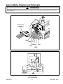
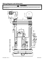
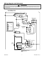
1
Amana Domestic Washer Technical Information 120 V, 60 Hz Models ALW480DA* PALW480DA* •Due to possibility of personal injury or property damage, always contact an authorized technician for servicing or repair of this unit. •Refer to Service Manual RS3100007 for detailed installation, operating, testing, troubleshooting, and disassembly instructions. •Refer to Parts Manual RP3100017 for part number information. ! CAUTION All safety information must be followed as provided in this Technical Sheet and in Service Manual RS3100007. ! WARNING To avoid risk of electrical shock, personal injury, or death, disconnect power to unit and discharge capacitor before servicing, unless testing requires it. Models Power Source Voltage AC Amperage (Single Unit) Frequency Motor horsepower Receptacle Plug Dimensions Cabinet Height− overall Height of cabinet Width Depth Clearance− washer lid Weight Crated March 2001 ALW480DA* 120 VAC 10 A 60 Hz 1/2 6-20R 6-20P 43” 36” 27” 28” 17 1/2” 193 lbs. Models Wash cycles Water temperatures Water level Features Steady Spin Balance System Self-cleaning lint filter Self-adjusting rear leveling legs 210 Agitation stroke Tri− Action wash system Fabric softener dispenser Extra rinse Motor speed Spin speed (revolutions per minute) Agitation speed (strokes per minute) High Medium 1 ALW480DA* 12 4 Variable X X X X X X X 2 speed 640 / 427 rpm 69 spm 46 spm RT3100007 Rev. 1 Component Testing Information ! WARNING To avoid risk of electrical shock, personal injury, or death, disconnect power to washer before servicing, unless testing requires it. Illustration 40046601 Component Temperature switch 2 1 40097701 Mixing valve 40073801 Timer Results >1 Ω L1-2 L1-1, L1-2, L2-2 L2-1, L2-L1, 1-2 Warm / Cold L1-1, L1-2, 1-2 Cold / Cold L1-1 Measure resistance of terminals on each valve. Resistance across each valve. Approximately 1000 Ω ± 10% Verify input and output voltage is present. See timing sequence chart for functional description of the component. Hot / Cold Warm / Warm L2 L1 Test Procedure Disconnect wires from component to properly measure the resistance of the component. Place switch in the following positions and measure across the terminals below: >1 Ω >1 Ω >1 Ω Verify wiring is correctly connected to the timer. 40055101 Pressure switch 2 1 3 40035001 R0000014 Lid switch− SPST Brake pad kit Do not disconnect the pressure hose from pressure switch to perform measurements. Measure resistance across the following terminals on the pressure switch: Terminal 1 to 2 Terminal 1 to 3 Disconnect wire terminals from switch. Test terminals with switch closed. Test terminals with switch open. If washtub does not stop spinning within seven seconds after opening loading door. If brake pads make noises. 038424W RT3100007 Rev. 1 Rocker switch (Extra Rinse) Measure resistance of switch positions: Closed (ON position) Open (OFF position) 2 Refer to wiring diagram/schematic for correct contacts. Air pressure that actuates switch is determined by the water level of the tub. Continuity (no pressure) Continuity (pressure) Continuity Infinite >1 Ω 1 MΩ Replace all three brake pads. Apply a thin layer of silicone (26594P) on pads, see Service Bulletin “ASQ− 213− B” Continuity Infinite >1 Ω 1 MΩ March 2001 Component Testing Information ! WARNING To avoid risk of electrical shock, personal injury, or death, disconnect power to washer before servicing, unless testing requires it. Illustration 40095003 Component Motor Test Procedure Type of motor: Two speed Results See following section “Internal Motor Diagram and Schematic” for correct wiring contacts. 40040301 Drain pump Verify drain pump is not clogged or damaged. Remove clog and verify proper operation. Replace drain pump if damaged. 40065301 Transmission assembly Type of transmission: 640 rpm Externally identical, must be identified by part number. If transmission locks-up, replace. 40053602 Drive belt Type of drive belt: 640 rpm Refer to “Parts Manual”, to verify which drive belt and pulley size is required. Refer to “Parts Manual” for proper pulley size. 40098701 Power Cord Measure resistance of wires. Continuity should be indicated on each wire. Verify polarity and grounding. March 2001 3 RT3100007 Rev. 1 Internal Motor Diagram and Schematic ! WARNING To avoid risk of electrical shock, personal injury, or death, disconnect power to washer before servicing, unless testing requires it. One or Two Speed Motors Continuity exists between switch terminal R and Red wire. Start Terminals YES Manually depress actuator. Continuity broken between switch terminal R and Red wire. YES Continuity exists between switch terminal P and Red wire. High Speed Terminals Low Speed Terminals NO NO Inoperative start switch. Replace switch. NO YES Manually depress actuator. Continuity broken between switch terminal P and Red wire. YES Continuity broken between switch terminal P and Violet wire. NO Inoperative high speed switch. Replace switch. NO YES Manually depress actuator. Continuity exists between switch terminal P and Violet wire. YES NO Inoperative low speed switch. Replace switch. Motor switch checks OK. Start Winding 4-5 ohms between Brown wire and Red wire. NO Inoperative start winding. Replace motor. NO Inoperative high speed winding. Replace motor. NO Inoperative low speed winding. Replace motor. NO Inoperative common lead. Replace motor. YES High Speed Winding 1-2 ohms between Blue wire and Yellow wire. YES Low Speed Winding 1-2 ohms between Yellow wire and Violet wire. YES Protector Continuity exists between Yellow wire and White wire. YES All motor windings checks OK. RT3100007 Rev. 1 4 March 2001 Internal Motor Diagram and Schematic ! WARNING To avoid risk of electrical shock, personal injury, or death, disconnect power to washer before servicing, unless testing requires it. BR W BU Y P R Wire harness connection block White Brown Yellow Red Blue G P W R White RUN BR BU Y START Violet Red Violet Blue Brown Yellow 4P M Yellow Overload protector 6P M Aux. Motor Assembly (two speed motor) March 2001 5 RT3100007 Rev. 1 RT3100007 Rev. 1 TM 6 18 16 6 8 10 11 14 5 LO EX TM K F G A 4 17 LO BP TM PS 15 3 19 22 24 21 20 BLU VLT BRN BLK 18 GA. BLU/WHT WHT/BLK PNK PNK WHT/RED GRY/BLK PNK/BLU PNK/BLU WHT/BLK GRY BLK/PNK RED BLU/BLK RED/BLK 24 PIN HOUSING GROUND TO TOP WHT GRN 1A EXTRA RINSE SWITCH 1 N.O. 4 POSITION TEMP. SWITCH ORG CONNECTOR L2 1 L1 2 2 3 COM. PNK/BLU ORG GRY WHT/RED GRN/YEL 9 1 3 2 POWER CORD PNK 7 BLU 6 VLT 5 BRN 4 WHT 8 RIDGE OR TINNED TERMINAL = NEUTRAL LID SWITCH PRESSURE SWITCH 1 GROUND TO TOP 9 7 6 5 4 8 1 3 2 WHT/RED PNK BLU VLT BRN WHT 5 8 3 7 1 6 4 5 8 3 7 1 6 4 RED NATURAL MOTOR HOUSING GRY ORG WHT/RED GRN/YEL GRN/YEL PLUG RECEPTACLE ! L P V W R H TIMER CONNECTION DIAGRAM GROUND TO CABINET MIXING VALVE HOT COLD Wiring Diagram and Schematic To avoid risk of electrical shock, personal injury, or death, disconnect power to washer before servicing, unless testing requires it. WARNING March 2001 Wiring Diagram and Schematic ! WARNING To avoid risk of electrical shock, personal injury, or death, disconnect power to washer before servicing, unless testing requires it. SCHEMATIC L1 N 120 VOLTS A.C. 60 HZ A EX PS A BP EXTRA RINSE SWITCH PRESSURE SWITCH MIXING VALVE COLD 3 1 2 HOT P LID SWITCH 4 POSITION WATER TEMP. SWITCH HOT COLD WARM WARM WARM COLD COLD COLD L1-2 N.O. L1-L2-1-2 V H L1-1-2 R W 4 POSITION L1 WATER TEMP. SWITCH L2 L1-1 SPRAY RINSES = COLD TM LO LO 1 2 TM HI 3 MOTOR HIGH K TIMER MOTOR LOW 7 F 4 1 L START 6 TP AGITATE K SPIN G 8 L INDICATES INTERNAL TIMER BUSS March 2001 7 RT3100007 Rev. 1 Timer Cycle Chart ! WARNING To avoid risk of electrical shock, personal injury, or death, disconnect power to washer before servicing, unless testing requires it. WATER TEMPERATURE SELECT MOTOR SPEED CYCLE TIME hh:mm:ss hot, warm, & cold hot, warm, & cold - S S 0:02:22 0:12:04 0:02:51 0:17:17 - - 0:03:43 PREWASH Fill & Agitate Pause Spin Pause hot, warm, & cold - F S - 0:05:04 0:00:29 0:02:31 0:00:29 0:08:33 REGULAR Wash: Fill & Agitate Pause Spin Spin & Spray Spin Pause Rinse: Fill & Agitate Pause Spin hot, warm, & cold cold warm, & cold - F F F F F F 0:14:04 0:00:29 0:02:38 0:00:27 0:02:26 0:00:29 0:02:31 0:00:29 0:05:31 0:29:04 CYCLE / FUNCTION SOAK Fill & Agitate Soak Spin OFF Pause for Extra Rinse Rinse: Fill & Agitate Pause Spin warm, & cold - F F 0:00:32 0:02:28 0:00:29 0:05:44 0:09:13 - - 0:03:43 PERMANENT PRESS/KNITS Wash: Fill & Agitate Pause hot, warm, & cold - F - 0:08:04 0:00:29 Spin Spin & Spray Spin Pause Rinse: Fill & Agitate Pause Spin cold warm, & cold - S S S F F 0:02:38 0:00:27 0:02:26 0:00:29 0:02:31 0:00:29 0:05:31 0:23:04 Pause for Extra Rinse Rinse: Fill & Agitate Pause Spin warm, & cold - F F 0:00:32 0:02:28 0:00:29 0:05:44 0:09:13 OFF WATER TEMPERATURE SELECT MOTOR SPEED CYCLE TIME hh:mm:ss hot, warm, & cold hot, warm, & cold hot, warm, & cold hot, warm, & cold hot, warm, & cold hot, warm, & cold hot, warm, & cold - S S S S 0:02:11 0:00:27 0:02:33 0:00:27 0:02:33 0:00:27 0:02:55 0:02:38 Spin & Spray Spin Pause Rinse: Fill & Agitate Pause Spin cold cold - S S S S 0:00:27 0:02:26 0:00:29 0:02:31 0:00:29 0:02:31 0:23:04 Pause for Extra Rinse Rinse: Fill & Agitate Pause Spin cold - S S 0:00:32 0:02:28 0:00:29 0:02:44 0:06:13 - - 0:03:43 hot, warm, & cold cold warm, & cold - F F F F F F 0:05:04 0:00:29 0:02:38 0:00:27 0:02:26 0:00:29 0:02:31 0:00:29 0:02:44 CYCLE / FUNCTION DELICATE Wash: Fill & Soak Agitate Soak Agitate Soak Agitate Soak Spin OFF Quick Wash Wash: Fill & Agitate Pause Spin Spin & Spray Spin Pause Rinse: Fill & Agitate Pause Spin 0:17:17 OFF RT3100007 Rev. 1 - OFF - - 0:03:43 0:03:43 8 March 2001