1
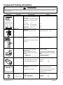
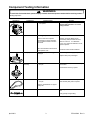
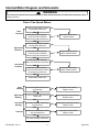
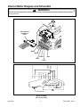
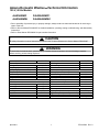
Amana Domestic WasherTechnical Information 120 V, 60 Hz Models ALW540RMC ALW540RMW PALW540RMC1 PALW540RMW1 • Due to possibility of personal injury or property damage, always contact an authorized technician for servicing or repair of this unit. • Refer to Service Manual RS3100007 for detailed installation, operating, testing, troubleshooting, and disassembly instructions. • Refer to Parts Manual RP3100020 for part number information. ! CAUTION All safety information must be followed as provided in this Technical Sheet and in Service Manual RS3100007. ! WARNING To avoid risk of electrical shock, personal injury, or death, disconnect power to unit and discharge capacitor before servicing, unless testing requires it. Models Power Source Voltage AC Amperage (minimum requirement) Amperage (maximum load) Frequency Motor horsepower Receptacle Plug Dimensions Cabinet Height−overall Height of cabinet Width Depth Clearance−washer lid Weight Crated April 2001 ALW540RM* 120 VAC 15 A 13 A 60 Hz 1/2 6-20R 6-20P 43” 36” 27” 28” 17 1/2” 193 lbs. Models Wash cycles Water temperatures Water level Features Steady Spin Balance System Self-cleaning lint filter Self-adjusting rear leveling legs 210 Agitation stroke Tri−Action wash system Fabric softener dispenser Extra rinse ALW540RM* 12 3 Variable Motor speed Spin speed (revolutions per minute) Agitation speed (strokes per minute) High Medium 2 speed 710 / 473 rpm 1 X X X X X X X 69 spm 46 spm RT3100022 Rev. 0 Component Testing Information ! WARNING To avoid risk of electrical shock, personal injury, or death, disconnect power to washer before servicing, unless testing requires it. Illustration 40077101 Component Temperature switch 2 1 Hot / Cold Warm / Warm L2 L1 Test Procedure Disconnect wires from component to properly measure the resistance of the component. Place switch in the following positions and measure across the terminals below: Warm / Cold Cold / Cold 40097701 Mixing valve 40058901 Timer L1-2 ........................... L1-1, L1-2, L2-2 L2-1, L2-L1, 1-2 ......... L1-1, L1-2, 1-2 ........... L1-1 ........................... Results >1 Ω >1 Ω >1 Ω >1 Ω Measure resistance of terminals on each valve. Resistance across each valve ............. Approximately 1000 Ω ± 10% Verify input and output voltage is present. See timing sequence chart for functional description of the component. Verify wiring is correctly connected to the timer. 40055101 Pressure switch 2 1 3 40035001 Lid switch−SPST Do not disconnect the pressure hose from pressure switch to perform measurements. Measure resistance across the following terminals on the pressure switch: Terminal 1 to 2 ................................ Terminal 1 to 3 ................................ Brake pad kit If washtub does not stop spinning within seven seconds after opening loading door. If brake pads make noises................... 038424* Rocker switch (Extra Rinse) *− Indicates color RT3100022 Rev. 0 Air pressure that actuates switch is determined by the water level of the tub. Continuity (no pressure) Continuity (pressure) Disconnect wire terminals from switch. Test terminals with switch closed ...... Test terminals with switch open......... R0000014 Refer to wiring diagram/schematic for correct contacts. Measure resistance of switch positions: Closed (ON position) ......................... Open (OFF position) ........................ 2 Continuity Infinite >1 Ω 1 MΩ Replace all three brake pads. Apply a thin layer of silicone (26594P) on pads, see Service Bulletin “ASQ−213−B” Continuity Infinite >1 Ω 1 MΩ April 2001 Component Testing Information ! WARNING To avoid risk of electrical shock, personal injury, or death, disconnect power to washer before servicing, unless testing requires it. Illustration 40116402 Component Motor Test Procedure Type of motor: Two speed 40084501 Capacitor Discharge Capacitors 40040301 Drain pump Results See following section “Internal Motor Diagram and Schematic” for correct wiring contacts. Remove wires from capacitor terminals and connect ohmmeter, set on highest resistance scale to terminals. Between Terminals: Meter should momentarily deflect towards zero then return to over 5 MΩ. If no deflection occurs, or if continuous deflection occurs, replace capacitor. Also check between each terminal and capacitor case. Verify drain pump is not clogged or damaged. Terminal to Case: Infinite resistance Remove clog and verify proper operation. Replace drain pump if damaged. 40032701 Transmission assembly Type of transmission: 710 rpm Externally identical, must be identified by part number. If transmission locks-up, replace. 40053601 Drive belt Type of drive belt: 710 rpm Refer to “Parts Manual”, to verify which drive belt and pulley size is required. Refer to “Parts Manual” for proper pulley size. 40098701 Power cord Measure resistance of wires. Continuity should be indicated on each wire. Verify polarity and grounding. April 2001 3 RT3100022 Rev. 0 Internal Motor Diagram and Schematic ! WARNING To avoid risk of electrical shock, personal injury, or death, disconnect power to washer before servicing, unless testing requires it. One or Two Speed Motors Continuity exists between switch terminal R and Red wire. Start Terminals YES Manually depress actuator. Continuity broken between switch terminal R and Red wire. YES Continuity exists between switch terminal P and Red wire. High Speed Terminals Low Speed Terminals NO NO Inoperative start switch. Replace switch. NO YES Manually depress actuator. Continuity broken between switch terminal P and Red wire. YES Continuity broken between switch terminal P and Violet wire. NO Inoperative high speed switch. Replace switch. NO YES Manually depress actuator. Continuity exists between switch terminal P and Violet wire. YES NO Inoperative low speed switch. Replace switch. Motor switch checks OK. Start Winding 4-5 ohms between Brown wire and Red wire. NO Inoperative start winding. Replace motor. NO Inoperative high speed winding. Replace motor. NO Inoperative low speed winding. Replace motor. NO Inoperative common lead. Replace motor. YES High Speed Winding 1-2 ohms between Blue wire and Yellow wire. YES Low Speed Winding 1-2 ohms between Yellow wire and Violet wire. YES Protector Continuity exists between Yellow wire and White wire. YES All motor windings checks OK. RT3100022 Rev. 0 4 April 2001 Internal Motor Diagram and Schematic ! WARNING To avoid risk of electrical shock, personal injury, or death, disconnect power to washer before servicing, unless testing requires it. BR W BU Y P R Wire harness connection block White Brown Yellow Red Blue WHITE RED BLUE 4 POLE MAIN VIOLET Y BU BR G W P R WHITE BR O W YE N LL O W RUN START Violet 6 POLE MAIN PROTECTOR AUX Motor Assembly (two speed motor) April 2001 5 RT3100022 Rev. 0 RT3100022 Rev. 0 6 F G A 10 11 14 5 K BLU VLT BRN BLU BLK 18 GA. BLU/WHT 6 9 PNK 8 WHT/RED GRY/BLK PNK/BLU PNK/BLU WHT/BLK 16 HI EX LO TM PS TM BP L GRY BLK/PNK BLU/BLK BLU/BLK RED/BLK 24 PIN HOUSING 3 1 GROUND TO TOP WHT GRN 1A EXTRA RINSE SWITCH 1 N.O. 3 POSITION TEMP. SWITCH ORG CONNECTOR A B GROUND TO CONTROL HOOD DIAGRAM 2 3 COM. PNK/BLU ORG GRY WHT/RED GRN/YEL 9 1 3 2 POWER CORD PNK 7 BLU 6 VLT 5 BRN 4 WHT 8 RIDGE OR TINNED TERMINAL = NEUTRAL LID SWITCH PRESSURE SWITCH 1 GROUND TO TOP GRN/YEL RECEPTACLE 9 7 6 5 4 8 1 3 2 SPIN VLT BRN WHT 5 8 3 7 1 6 4 RED WHT/RED PNK BLU GRN/YEL 5 8 3 7 1 6 4 RED NATURAL HOT COLD CAPACITOR MOTOR HOUSING GRY ORG WHT/RED PLUG GRN/YEL GROUND TO CABINET MIXING VALVE ! 15 3 4 21 20 H P 19 22 V W TIMER CONNECTION Wiring Diagram and Schematic To avoid risk of electrical shock, personal injury, or death, disconnect power to washer before servicing, unless testing requires it. WARNING April 2001 Wiring Diagram and Schematic ! WARNING To avoid risk of electrical shock, personal injury, or death, disconnect power to washer before servicing, unless testing requires it. SCHEMATIC L1 N 120 VOLTS A.C. 60 HZ A BP PS A EX PRESSURE SWITCH 3 1 2 EXTRA RINSE SWITCH TEMP. SWITCH A-1 HOT P LID SWITCH 3 POSITION WATER HOT COLD WARM COLD COLD COLD MIXING VALVE COLD V H N.O. W 3 POSITION WATER TEMP. SWITCH A-1, B-3 B A B-3 SPRAY RINSES = COLD LO TM 3 1 LO TM HI 3 K F 4 1 L START 6 AGITATE K G MOTOR HIGH 7 TIMER MOTOR LOW 8 TP SPIN L INDICATES INTERNAL TIMER BUSS April 2001 7 RT3100022 Rev. 0 Timer Cycle Chart To avoid risk of electrical shock, personal injury, or death, disconnect power to washer before servicing, unless testing requires it. R A D T SWITCH FUNCTION FILL TERM IDENT SPIN AGITATE MOTOR HI B EX RINSE ENABLE G-K F-K F-L TM-HI A-BP A-EX A-PS SPIN G-L T PRES/SW BYPASS AGITATE TM-LO T 12 B T B T B T B T MOTOR LO MOTOR LO P-V P-H TM-LO COLD WATER HOT WATER V-W T INTERVAL NUMBER ST O PM F I F N 6 S S S P P & P A I S I U N N S E R I N S E P A U S E C C P A U S E C 90 A 80 170 R I N S E W A S H P A U S E ST P PM A I U N S E R I N S E P A U S E ST O PM F I F N W A S H S O A K W A S H S O A K S S S P P & P A I S I U N N S E HAND WASH EXTRA RINSE S O A K 330 DELICATE R I N S E R I N S E PST O APM F UI F SN E W A S H 360 S S S P P & P A I S I U N N S E 350 S O A K 320 A C C 340 W A S H B B 310 S O A K 300 S O A K 290 EXTRARINSE W A S H 280 S O A K 270 A C CC C 260 P T O A SPIN M F U F S E 240 CONTACTS OPEN TPR S MA I P UN I SS N EE 230 B B B 250 PART NO. 40118201 220 P A U S E CC 210 S S S P P & P A I S I U N N S E 180 C 200 PERMANENTPRESS P A U S E A 160 WASH 150 CONTACTS CLOSED 190 EXTRA RINSE 130 P T O A SPIN M F U F S E 120 TPR MA I UN SS EE C C 110 SPIN 100 THIS MACHINE MANUFACTURED UNDER ONE OR MORE OF THE FOLLOWING PATENTS: UNITED STATES NO: 3,253,874; 3,838,755; 3,8453642 CANADIAN NO: 1,008,265; 994,685 OTHER PATENTS PENDING 140 Failure to install, maintain, and/or operate this machine according to manufacture's instructions may result in conditions which can produce bodily injury and/or property damage. 70 REGULARWASH WASH 60 7 8 9 10 11 12 13 14 15 16 17 18 19 20 21 22 23 24 25 26 27 28 29 30 31 32 33 34 35 36 37 38 39 40 41 42 43 44 45 46 47 48 49 50 51 52 50 SOAK 5 40 SOAK 4 30 W A S H 2 3 DEGREES 1 20 TIMER CHART WASH 10 B 8 6 4 2 0B CAM 14 B 10 PS EX HI L L LO H A A TM F K LO K TM V W P G BP KEY "A" INDICATES 27 SECOND WATER ON ±7 SECONDS. "B" INDICATES 27 SECOND MOTOR ON ±7 SECONDS. V 3 5 2 4 1 24 PIN HOUSING WIRE POSITION 6 GRY/ BLK 9 8 11 10 7 BLU/ BLK PNK/ BLU WHT X2 VLT 13 BLU X2 17 19 PNK 16 14 BLU WHT/ BLK 12 15 18 20 WHT/ BRN RED 21 23 BLK/ PNK 22 BLU/ RED/ GRY BLK BLK 24 April 2001 8 RT3100022 Rev. 0 WARNING !