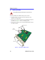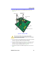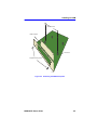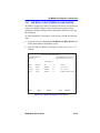
1
HSIM-A6DP User’s Guide APIM 1 R 9032077-06 HSIM-A6DP APIM 2 R Only qualified personnel should perform installation procedures. NOTICE Cabletron Systems reserves the right to make changes in specifications and other information contained in this document without prior notice. The reader should in all cases consult Cabletron Systems to determine whether any such changes have been made. The hardware, firmware, or software described in this manual is subject to change without notice. IN NO EVENT SHALL CABLETRON SYSTEMS BE LIABLE FOR ANY INCIDENTAL, INDIRECT, SPECIAL, OR CONSEQUENTIAL DAMAGES WHATSOEVER (INCLUDING BUT NOT LIMITED TO LOST PROFITS) ARISING OUT OF OR RELATED TO THIS MANUAL OR THE INFORMATION CONTAINED IN IT, EVEN IF CABLETRON SYSTEMS HAS BEEN ADVISED OF, KNOWN, OR SHOULD HAVE KNOWN, THE POSSIBILITY OF SUCH DAMAGES. 1999 by Cabletron Systems, Inc., P.O. Box 5005, Rochester, NH 03866-5005 All Rights Reserved Printed in the United States of America Part Number: 9032077-06 March 1999 Cabletron Systems, LANVIEW, and SecureFast are registered trademarks; and SmartSwitch is a trademark of Cabletron Systems, Inc. All other product names mentioned in this manual may be trademarks or registered trademarks of their respective companies. HSIM-A6DP User’s Guide i Notice FCC NOTICE This device complies with Part 15 of the FCC rules. Operation is subject to the following two conditions: (1) this device may not cause harmful interference, and (2) this device must accept any interference received, including interference that may cause undesired operation. NOTE: This equipment has been tested and found to comply with the limits for a Class A digital device, pursuant to Part 15 of the FCC rules. These limits are designed to provide reasonable protection against harmful interference when the equipment is operated in a commercial environment. This equipment uses, generates, and can radiate radio frequency energy and if not installed in accordance with the operator’s manual, may cause harmful interference to radio communications. Operation of this equipment in a residential area is likely to cause interference in which case the user will be required to correct the interference at his own expense. WARNING: Changes or modifications made to this device which are not expressly approved by the party responsible for compliance could void the user’s authority to operate the equipment. INDUSTRY CANADA NOTICE This digital apparatus does not exceed the Class A limits for radio noise emissions from digital apparatus set out in the Radio Interference Regulations of the Canadian Department of Communications. Le présent appareil numérique n’émet pas de bruits radioélectriques dépassant les limites applicables aux appareils numériques de la class A prescrites dans le Règlement sur le brouillage radioélectrique édicté par le ministère des Communications du Canada. VCCI NOTICE This is a Class A product based on the standard of the Voluntary Control Council for Interference by Information Technology Equipment (VCCI). If this equipment is used in a domestic environment, radio disturbance may arise. When such trouble occurs, the user may be required to take corrective actions. ii HSIM-A6DP User’s Guide Notice CABLETRON SYSTEMS, INC. PROGRAM LICENSE AGREEMENT IMPORTANT: THIS LICENSE APPLIES FOR USE OF PRODUCT IN THE FOLLOWING GEOGRAPHICAL REGIONS: CANADA MEXICO CENTRAL AMERICA SOUTH AMERICA BEFORE OPENING OR UTILIZING THE ENCLOSED PRODUCT, CAREFULLY READ THIS LICENSE AGREEMENT. This document is an agreement (“Agreement”) between You, the end user, and Cabletron Systems, Inc. (“Cabletron”) that sets forth your rights and obligations with respect to the Cabletron software program (“Program”) in the package. The Program may be contained in firmware, chips or other media. UTILIZING THE ENCLOSED PRODUCT, YOU ARE AGREEING TO BECOME BOUND BY THE TERMS OF THIS AGREEMENT, WHICH INCLUDES THE LICENSE AND THE LIMITATION OF WARRANTY AND DISCLAIMER OF LIABILITY. IF YOU DO NOT AGREE TO THE TERMS OF THIS AGREEMENT, RETURN THE UNOPENED PRODUCT TO CABLETRON OR YOUR DEALER, IF ANY, WITHIN TEN (10) DAYS FOLLOWING THE DATE OF RECEIPT FOR A FULL REFUND. IF YOU HAVE ANY QUESTIONS ABOUT THIS AGREEMENT, CONTACT CABLETRON SYSTEMS (603) 332-9400. Attn: Legal Department. 1. LICENSE. You have the right to use only the one (1) copy of the Program provided in this package subject to the terms and conditions of this License Agreement. You may not copy, reproduce or transmit any part of the Program except as permitted by the Copyright Act of the United States or as authorized in writing by Cabletron. 2. OTHER RESTRICTIONS. You may not reverse engineer, decompile, or disassemble the Program. 3. APPLICABLE LAW. This License Agreement shall be interpreted and governed under the laws and in the state and federal courts of New Hampshire. You accept the personal jurisdiction and venue of the New Hampshire courts. 4. EXPORT REQUIREMENTS. You understand that Cabletron and its Affiliates are subject to regulation by agencies of the U.S. Government, including the U.S. Department of Commerce, which prohibit export or diversion of certain technical products to certain countries, unless a license to export the product is obtained from the U.S. Government or an exception from obtaining such license may be relied upon by the exporting party. If the Program is exported from the United States pursuant to the License Exception CIV under the U.S. Export Administration Regulations, You agree that You are a civil end user of the Program and agree that You will use the Program for civil end uses only and not for military purposes. HSIM-A6DP User’s Guide iii Notice If the Program is exported from the United States pursuant to the License Exception TSR under the U.S. Export Administration Regulations, in addition to the restriction on transfer set forth in Sections 1 or 2 of this Agreement, You agree not to (i) reexport or release the Program, the source code for the Program or technology to a national of a country in Country Groups D:1 or E:2 (Albania, Armenia, Azerbaijan, Belarus, Bulgaria, Cambodia, Cuba, Estonia, Georgia, Iraq, Kazakhstan, Kyrgyzstan, Laos, Latvia, Libya, Lithuania, Moldova, North Korea, the People’s Republic of China, Romania, Russia, Rwanda, Tajikistan, Turkmenistan, Ukraine, Uzbekistan, Vietnam, or such other countries as may be designated by the United States Government), (ii) export to Country Groups D:1 or E:2 (as defined herein) the direct product of the Program or the technology, if such foreign produced direct product is subject to national security controls as identified on the U.S. Commerce Control List, or (iii) if the direct product of the technology is a complete plant o r any major component of a plant, export to Country Groups D:1 or E:2 the direct product of the plant or a major component thereof, if such foreign produced direct product is subject to national security controls as identified on the U.S. Commerce Control List or is subject to State Department controls under the U.S. Munitions List. 5. UNITED STATES GOVERNMENT RESTRICTED RIGHTS. The enclosed Product (i) was developed solely at private expense; (ii) contains “restricted computer software” submitted with restricted rights in accordance with section 52.227-19 (a) through (d) of the Commercial Computer Software-Restricted Rights Clause and its successors, and (iii) in all respects is proprietary data belonging to Cabletron and/or its suppliers. For Department of Defense units, the Product is considered commercial computer software in accordance with DFARS section 227.7202-3 and its successors, and use, duplication, or disclosure by the Government is subject to restrictions set forth herein. 6. EXCLUSION OF WARRANTY. Except as may be specifically provided by Cabletron in writing, Cabletron makes no warranty, expressed or implied, concerning the Program (including its documentation and media). CABLETRON DISCLAIMS ALL WARRANTIES, OTHER THAN THOSE SUPPLIED TO YOU BY CABLETRON IN WRITING, EITHER EXPRESS OR IMPLIED, INCLUDING BUT NOT LIMITED TO IMPLIED WARRANTIES OF MERCHANTABILITY AND FITNESS FOR A PARTICULAR PURPOSE, WITH RESPECT TO THE PROGRAM, THE ACCOMPANYING WRITTEN MATERIALS, AND ANY ACCOMPANYING HARDWARE. 7. NO LIABILITY FOR CONSEQUENTIAL DAMAGES. IN NO EVENT SHALL CABLETRON OR ITS SUPPLIERS BE LIABLE FOR ANY DAMAGES WHATSOEVER (INCLUDING, WITHOUT LIMITATION, DAMAGES FOR LOSS OF BUSINESS, PROFITS, BUSINESS INTERRUPTION, LOSS OF BUSINESS INFORMATION, SPECIAL, INCIDENTAL, CONSEQUENTIAL, OR RELIANCE DAMAGES, OR OTHER LOSS) ARISING OUT OF THE USE OR INABILITY TO USE THIS CABLETRON PRODUCT, EVEN IF CABLETRON HAS BEEN ADVISED OF THE POSSIBILITY OF SUCH DAMAGES. BECAUSE SOME STATES DO NOT ALLOW THE EXCLUSION OR LIMITATION OF LIABILITY FOR CONSEQUENTIAL OR INCIDENTAL DAMAGES, OR IN THE DURATION OR LIMITATION OF IMPLIED WARRANTIES IN SOME INSTANCES, THE ABOVE LIMITATION AND EXCLUSIONS MAY NOT APPLY TO YOU. iv HSIM-A6DP User’s Guide Notice CABLETRON SYSTEMS SALES AND SERVICE, INC. PROGRAM LICENSE AGREEMENT IMPORTANT: THIS LICENSE APPLIES FOR USE OF PRODUCT IN THE UNITED STATES OF AMERICA AND BY UNITED STATES OF AMERICA GOVERNMENT END USERS. BEFORE OPENING OR UTILIZING THE ENCLOSED PRODUCT, CAREFULLY READ THIS LICENSE AGREEMENT. This document is an agreement (“Agreement”) between You, the end user, and Cabletron Systems Sales and Service, Inc. (“Cabletron”) that sets forth your rights and obligations with respect to the Cabletron software program (“Program”) in the package. The Program may be contained in firmware, chips or other media. UTILIZING THE ENCLOSED PRODUCT, YOU ARE AGREEING TO BECOME BOUND BY THE TERMS OF THIS AGREEMENT, WHICH INCLUDES THE LICENSE AND THE LIMITATION OF WARRANTY AND DISCLAIMER OF LIABILITY. IF YOU DO NOT AGREE TO THE TERMS OF THIS AGREEMENT, RETURN THE UNOPENED PRODUCT TO CABLETRON OR YOUR DEALER, IF ANY, WITHIN TEN (10) DAYS FOLLOWING THE DATE OF RECEIPT FOR A FULL REFUND. IF YOU HAVE ANY QUESTIONS ABOUT THIS AGREEMENT, CONTACT CABLETRON SYSTEMS (603) 332-9400. Attn: Legal Department. 1. LICENSE. You have the right to use only the one (1) copy of the Program provided in this package subject to the terms and conditions of this License Agreement. You may not copy, reproduce or transmit any part of the Program except as permitted by the Copyright Act of the United States or as authorized in writing by Cabletron. 2. OTHER RESTRICTIONS. You may not reverse engineer, decompile, or disassemble the Program. 3. APPLICABLE LAW. This License Agreement shall be interpreted and governed under the laws and in the state and federal courts of New Hampshire. You accept the personal jurisdiction and venue of the New Hampshire courts. 4. EXPORT REQUIREMENTS. You understand that Cabletron and its Affiliates are subject to regulation by agencies of the U.S. Government, including the U.S. Department of Commerce, which prohibit export or diversion of certain technical products to certain countries, unless a license to export the product is obtained from the U.S. Government or an exception from obtaining such license may be relied upon by the exporting party. If the Program is exported from the United States pursuant to the License Exception CIV under the U.S. Export Administration Regulations, You agree that You are a civil end user of the Program and agree that You will use the Program for civil end uses only and not for military purposes. HSIM-A6DP User’s Guide v Notice If the Program is exported from the United States pursuant to the License Exception TSR under the U.S. Export Administration Regulations, in addition to the restriction on transfer set forth in Sections 1 or 2 of this Agreement, You agree not to (i) reexport or release the Program, the source code for the Program or technology to a national of a country in Country Groups D:1 or E:2 (Albania, Armenia, Azerbaijan, Belarus, Bulgaria, Cambodia, Cuba, Estonia, Georgia, Iraq, Kazakhstan, Kyrgyzstan, Laos, Latvia, Libya, Lithuania, Moldova, North Korea, the People’s Republic of China, Romania, Russia, Rwanda, Tajikistan, Turkmenistan, Ukraine, Uzbekistan, Vietnam, or such other countries as may be designated by the United States Government), (ii) export to Country Groups D:1 or E:2 (as defined herein) the direct product of the Program or the technology, if such foreign produced direct product is subject to national security controls as identified on the U.S. Commerce Control List, or (iii) if the direct product of the technology is a complete plant o r any major component of a plant, export to Country Groups D:1 or E:2 the direct product of the plant or a major component thereof, if such foreign produced direct product is subject to national security controls as identified on the U.S. Commerce Control List or is subject to State Department controls under the U.S. Munitions List. 5. UNITED STATES GOVERNMENT RESTRICTED RIGHTS. The enclosed Product (i) was developed solely at private expense; (ii) contains “restricted computer software” submitted with restricted rights in accordance with section 52.227-19 (a) through (d) of the Commercial Computer Software-Restricted Rights Clause and its successors, and (iii) in all respects is proprietary data belonging to Cabletron and/or its suppliers. For Department of Defense units, the Product is considered commercial computer software in accordance with DFARS section 227.7202-3 and its successors, and use, duplication, or disclosure by the Government is subject to restrictions set forth herein. 6. EXCLUSION OF WARRANTY. Except as may be specifically provided by Cabletron in writing, Cabletron makes no warranty, expressed or implied, concerning the Program (including its documentation and media). CABLETRON DISCLAIMS ALL WARRANTIES, OTHER THAN THOSE SUPPLIED TO YOU BY CABLETRON IN WRITING, EITHER EXPRESS OR IMPLIED, INCLUDING BUT NOT LIMITED TO IMPLIED WARRANTIES OF MERCHANTABILITY AND FITNESS FOR A PARTICULAR PURPOSE, WITH RESPECT TO THE PROGRAM, THE ACCOMPANYING WRITTEN MATERIALS, AND ANY ACCOMPANYING HARDWARE. 7. NO LIABILITY FOR CONSEQUENTIAL DAMAGES. IN NO EVENT SHALL CABLETRON OR ITS SUPPLIERS BE LIABLE FOR ANY DAMAGES WHATSOEVER (INCLUDING, WITHOUT LIMITATION, DAMAGES FOR LOSS OF BUSINESS, PROFITS, BUSINESS INTERRUPTION, LOSS OF BUSINESS INFORMATION, SPECIAL, INCIDENTAL, CONSEQUENTIAL, OR RELIANCE DAMAGES, OR OTHER LOSS) ARISING OUT OF THE USE OR INABILITY TO USE THIS CABLETRON PRODUCT, EVEN IF CABLETRON HAS BEEN ADVISED OF THE POSSIBILITY OF SUCH DAMAGES. BECAUSE SOME STATES DO NOT ALLOW THE EXCLUSION OR LIMITATION OF LIABILITY FOR CONSEQUENTIAL OR INCIDENTAL DAMAGES, OR IN THE DURATION OR LIMITATION OF IMPLIED WARRANTIES IN SOME INSTANCES, THE ABOVE LIMITATION AND EXCLUSIONS MAY NOT APPLY TO YOU. vi HSIM-A6DP User’s Guide Notice CABLETRON SYSTEMS LIMITED PROGRAM LICENSE AGREEMENT IMPORTANT: THIS LICENSE APPLIES FOR THE USE OF THE PRODUCT IN THE FOLLOWING GEOGRAPHICAL REGIONS: EUROPE MIDDLE EAST AFRICA ASIA AUSTRALIA PACIFIC RIM BEFORE OPENING OR UTILIZING THE ENCLOSED PRODUCT, CAREFULLY READ THIS LICENSE AGREEMENT. This document is an agreement (“Agreement”) between You, the end user, and Cabletron Systems Limited (“Cabletron”) that sets forth your rights and obligations with respect to the Cabletron software program (“Program”) in the package. The Program may be contained in firmware, chips or other media. UTILIZING THE ENCLOSED PRODUCT, YOU ARE AGREEING TO BECOME BOUND BY THE TERMS OF THIS AGREEMENT, WHICH INCLUDES THE LICENSE AND THE LIMITATION OF WARRANTY AND DISCLAIMER OF LIABILITY. IF YOU DO NOT AGREE TO THE TERMS OF THIS AGREEMENT, RETURN THE UNOPENED PRODUCT TO CABLETRON OR YOUR DEALER, IF ANY, WITHIN TEN (10) DAYS FOLLOWING THE DATE OF RECEIPT FOR A FULL REFUND. IF YOU HAVE ANY QUESTIONS ABOUT THIS AGREEMENT, CONTACT CABLETRON SYSTEMS (603) 332-9400. Attn: Legal Department. 1. LICENSE. You have the right to use only the one (1) copy of the Program provided in this package subject to the terms and conditions of this License Agreement. You may not copy, reproduce or transmit any part of the Program except as permitted by the Copyright Act of the United States or as authorized in writing by Cabletron. 2. OTHER RESTRICTIONS. You may not reverse engineer, decompile, or disassemble the Program. 3. APPLICABLE LAW. This License Agreement shall be governed in accordance with English law. The English courts shall have exclusive jurisdiction in the event of any disputes. 4. EXPORT REQUIREMENTS. You understand that Cabletron and its Affiliates are subject to regulation by agencies of the U.S. Government, including the U.S. Department of Commerce, which prohibit export or diversion of certain technical products to certain countries, unless a license to export the product is obtained from the U.S. Government or an exception from obtaining such license may be relied upon by the exporting party. If the Program is exported from the United States pursuant to the License Exception CIV under the U.S. Export Administration Regulations, You agree that You are a civil end user of the Program and agree that You will use the Program for civil end uses only and not for military purposes. HSIM-A6DP User’s Guide vii Notice If the Program is exported from the United States pursuant to the License Exception TSR under the U.S. Export Administration Regulations, in addition to the restriction on transfer set forth in Sections 1 or 2 of this Agreement, You agree not to (i) reexport or release the Program, the source code for the Program or technology to a national of a country in Country Groups D:1 or E:2 (Albania, Armenia, Azerbaijan, Belarus, Bulgaria, Cambodia, Cuba, Estonia, Georgia, Iraq, Kazakhstan, Kyrgyzstan, Laos, Latvia, Libya, Lithuania, Moldova, North Korea, the People’s Republic of China, Romania, Russia, Rwanda, Tajikistan, Turkmenistan, Ukraine, Uzbekistan, Vietnam, or such other countries as may be designated by the United States Government), (ii) export to Country Groups D:1 or E:2 (as defined herein) the direct product of the Program or the technology, if such foreign produced direct product is subject to national security controls as identified on the U.S. Commerce Control List, or (iii) if the direct product of the technology is a complete plant o r any major component of a plant, export to Country Groups D:1 or E:2 the direct product of the plant or a major component thereof, if such foreign produced direct product is subject to national security controls as identified on the U.S. Commerce Control List or is subject to State Department controls under the U.S. Munitions List. 5. UNITED STATES GOVERNMENT RESTRICTED RIGHTS. The enclosed Product (i) was developed solely at private expense; (ii) contains “restricted computer software” submitted with restricted rights in accordance with section 52.227-19 (a) through (d) of the Commercial Computer Software-Restricted Rights Clause and its successors, and (iii) in all respects is proprietary data belonging to Cabletron and/or its suppliers. For Department of Defense units, the Product is considered commercial computer software in accordance with DFARS section 227.7202-3 and its successors, and use, duplication, or disclosure by the Government is subject to restrictions set forth herein. 6. EXCLUSION OF WARRANTY. Except as may be specifically provided by Cabletron in writing, Cabletron makes no warranty, expressed or implied, concerning the Program (including its documentation and media). CABLETRON DISCLAIMS ALL WARRANTIES, OTHER THAN THOSE SUPPLIED TO YOU BY CABLETRON IN WRITING, EITHER EXPRESS OR IMPLIED, INCLUDING BUT NOT LIMITED TO IMPLIED WARRANTIES OF MERCHANTABILITY AND FITNESS FOR A PARTICULAR PURPOSE, WITH RESPECT TO THE PROGRAM, THE ACCOMPANYING WRITTEN MATERIALS, AND ANY ACCOMPANYING HARDWARE. 7. NO LIABILITY FOR CONSEQUENTIAL DAMAGES. IN NO EVENT SHALL CABLETRON OR ITS SUPPLIERS BE LIABLE FOR ANY DAMAGES WHATSOEVER (INCLUDING, WITHOUT LIMITATION, DAMAGES FOR LOSS OF BUSINESS, PROFITS, BUSINESS INTERRUPTION, LOSS OF BUSINESS INFORMATION, SPECIAL, INCIDENTAL, CONSEQUENTIAL, OR RELIANCE DAMAGES, OR OTHER LOSS) ARISING OUT OF THE USE OR INABILITY TO USE THIS CABLETRON PRODUCT, EVEN IF CABLETRON HAS BEEN ADVISED OF THE POSSIBILITY OF SUCH DAMAGES. BECAUSE SOME STATES DO NOT ALLOW THE EXCLUSION OR LIMITATION OF LIABILITY FOR CONSEQUENTIAL OR INCIDENTAL DAMAGES, OR IN THE DURATION OR LIMITATION OF IMPLIED WARRANTIES IN SOME INSTANCES, THE ABOVE LIMITATION AND EXCLUSIONS MAY NOT APPLY TO YOU. viii HSIM-A6DP User’s Guide Notice SAFETY INFORMATION CLASS 1 LASER TRANSCEIVERS THE FE-100F3 FAST ETHERNET INTERFACE MODULE, FPIM-05 AND FPIM-07 FDDI PORT INTERFACE MODULES, AND APIM-29 ATM PORT INTERFACE MODULE USE CLASS 1 LASER TRANSCEIVERS. READ THE FOLLOWING SAFETY INFORMATION BEFORE INSTALLING OR OPERATING THESE MODULES. The Class 1 laser transceivers use an optical feedback loop to maintain Class 1 operation limits. This control loop eliminates the need for maintenance checks or adjustments. The output is factory set, and does not allow any user adjustment. Class 1 laser transceivers comply with the following safety standards: • 21 CFR 1040.10 and 1040.11 U.S. Department of Health and Human Services (FDA). • IEC Publication 825 (International Electrotechnical Commission). • CENELEC EN 60825 (European Committee for Electrotechnical Standardization). When operating within their performance limitations, laser transceiver output meets the Class 1 accessible emission limit of all three standards. Class 1 levels of laser radiation are not considered hazardous. SAFETY INFORMATION CLASS 1 LASER TRANSCEIVERS LASER RADIATION AND CONNECTORS When the connector is in place, all laser radiation remains within the fiber. The maximum amount of radiant power exiting the fiber (under normal conditions) is -12.6 dBm or 55 x 10-6 watts. Removing the optical connector from the transceiver allows laser radiation to emit directly from the optical port. The maximum radiance from the optical port (under worst case conditions) is 0.8 W cm-2 or 8 x 10³ W m2 sr-1. Do not use optical instruments to view the laser output. The use of optical instruments to view laser output increases eye hazard. When viewing the output optical port, power must be removed from the network adapter. HSIM-A6DP User’s Guide ix Notice DECLARATION OF CONFORMITY Application of Council Directive(s): Manufacturer’s Name: Manufacturer’s Address: European Representative Name: European Representative Address: Conformance to Directive(s)/Product Standards: Equipment Type/Environment: 89/336/EEC 73/23/EEC Cabletron Systems, Inc. 35 Industrial Way PO Box 5005 Rochester, NH 03867 Mr. J. Solari Cabletron Systems Limited Nexus House, Newbury Business Park London Road, Newbury Berkshire RG13 2PZ, England EC Directive 89/336/EEC EC Directive 73/23/EEC EN 55022 EN 50082-1 EN 60950 Networking Equipment, for use in a Commercial or Light Industrial Environment. We the undersigned, hereby declare, under our sole responsibility, that the equipment packaged with this notice conforms to the above directives. Manufacturer Legal Representative in Europe Mr. Ronald Fotino ___________________________________ Full Name Mr. J. Solari ___________________________________ Full Name Principal Compliance Engineer ___________________________________ Title Managing Director - E.M.E.A. ___________________________________ Title Rochester, NH, USA ___________________________________ Location Newbury, Berkshire, England ___________________________________ Location x HSIM-A6DP User’s Guide CONTENTS Figures ....................................................................................................xv Tables.................................................................................................... xvii PREFACE Who Should Use This Guide ........................................................ xix Using This Manual........................................................................ xix Related Manuals............................................................................xx Document Conventions ................................................................ xxi CHAPTER 1 INTRODUCTION 1.1 Overview...................................................................................... 1-1 1.1.1 ATM Port Interface Modules (APIMs) ............................. 1-2 1.1.2 MIB Support .................................................................... 1-2 1.1.3 LANVIEW Diagnostic LEDs ............................................ 1-2 1.2 Getting Help................................................................................. 1-3 CHAPTER 2 INSTALLATION 2.1 Unpacking the HSIM.................................................................... 2-1 2.2 Installing APIMs........................................................................... 2-2 2.3 Installing an HSIM ....................................................................... 2-4 2.3.1 Installing an HSIM in an Interface Module ...................... 2-4 2.3.2 Installing an HSIM in a Standalone Device..................... 2-7 CHAPTER 3 LOCAL MANAGEMENT 3.1 Using Local Management Screens.............................................. 3-2 3.1.1 Local Management Screen Elements ............................. 3-2 3.1.2 Local Management Keyboard Conventions .................... 3-5 3.1.3 Navigating Local Management Screens ......................... 3-5 3.1.3.1 Selecting Local Management Menu Screen Items .................................................. 3-7 3.1.3.2 Exiting Local Management Screens............... 3-7 3.2 Accessing the HSIM-A6DP ATM Screen..................................... 3-8 3.3 ATM Connections Screen.......................................................... 3-11 3.4 ATM Connection Setup Screen ................................................. 3-12 HSIM-A6DP User’s Guide xi Contents 3.5 3.6 3.7 3.8 3.9 3.10 3.11 3.12 3.13 3.14 3.15 3.16 3.17 3.18 xii Add/Delete Entry Screen ...........................................................3-16 3.5.1 Adding an Entry (PVC) ..................................................3-18 3.5.2 Modifying an Entry (PVC)..............................................3-18 3.5.3 Deleting an Entry (PVC) ................................................3-19 ATM Setup by Virtual Interface Screen......................................3-20 3.6.1 Selecting a Virtual Interface ..........................................3-22 Physical Port Configuration Menu Screen .................................3-23 Port Framer Configuration Screen .............................................3-25 3.8.1 Configuring an APIM .....................................................3-27 ATM Redundancy Configuration Screen ...................................3-28 3.9.1 Setting the Redundancy Status.....................................3-31 3.9.2 Setting the Primary Port ................................................3-31 3.9.3 Setting the Active Port...................................................3-32 3.9.4 Setting the Activation of Redundant Port Field..............3-32 3.9.5 Setting the Revert to Primary Port Field........................3-32 3.9.6 Setting the Periodic Test Status Field ...........................3-33 3.9.7 Setting the Periodic Test Time ......................................3-33 3.9.8 Using the TEST PORTS NOW Command ....................3-34 3.9.9 Using the RESET TO FACTORY DEFAULTS Command......................................................................3-34 ATM LEC Screen .......................................................................3-35 ATM LEC Table Screen .............................................................3-37 LEC Administration Screen ........................................................3-40 3.12.1 Changing the LEC Status of an Existing LEC ...............3-43 3.12.2 Configuring a New LEC Automatically ..........................3-44 3.12.3 Configuring a New LEC Manually .................................3-45 3.12.4 Modifying an Existing LEC ............................................3-46 3.12.5 Deleting an Existing LEC...............................................3-48 ELAN Properties Screen ............................................................3-49 3.13.1 Viewing Multiple ELANs ................................................3-52 LEC ARP Cache Screen ............................................................3-53 3.14.1 Performing a Search .....................................................3-55 Traffic Management LEC Priority Queues Screen .....................3-56 3.15.1 Assigning a Traffic Profile to a LEC...............................3-58 Signalling Screen .......................................................................3-60 3.16.1 Changing the UNI Version.............................................3-62 3.16.2 Changing the ILMI Status to Disabled...........................3-62 3.16.3 Changing the UNI Status...............................................3-63 3.16.4 Restarting UNI...............................................................3-63 3.16.5 Restarting the ILMI ........................................................3-63 The MPOA Client Menu Screen.................................................3-64 The MPC Table Screen .............................................................3-67 HSIM-A6DP User’s Guide Contents 3.19 The MPC Client Administration Screen ..................................... 3-69 3.19.1 Creating an MPC .......................................................... 3-72 3.19.2 Modifying an MPC ........................................................ 3-74 3.19.3 Deleting an MPC........................................................... 3-76 3.20 The MPOA Client Properties Screen......................................... 3-77 3.20.1 Viewing an MPC ........................................................... 3-79 3.21 The MPOA Client Assignment Screen ...................................... 3-80 3.21.1 Assigning a LEC to an MPC ......................................... 3-82 3.22 MPOA Client Operational Summary Screen ............................. 3-84 3.22.1 Selecting an MPC ......................................................... 3-89 3.23 MPOA Client Statistics Screen .................................................. 3-90 3.23.1 Selecting an MPC ......................................................... 3-95 3.23.2 Using the CLEAR Command ........................................ 3-95 3.24 The MPOA Client Ingress Cache Screen .................................. 3-96 3.24.1 Selecting an MPC ....................................................... 3-100 3.25 The MPOA Client Egress Cache Screen................................. 3-101 3.25.1 Selecting an MPC ....................................................... 3-103 3.26 Traffic Management Descriptor Profiles Screen...................... 3-104 3.26.1 Creating a Traffic Profile ............................................. 3-108 3.27 Enabling LANE Services ......................................................... 3-110 3.28 LANE Services Configuration Menu Screen............................ 3-113 3.29 ELAN Table Screen................................................................. 3-115 3.30 LANE Services Configuration Screen...................................... 3-117 3.30.1 Creating an ELAN ....................................................... 3-119 3.30.2 Deleting an ELAN ....................................................... 3-119 3.31 Client Info Screen .................................................................... 3-120 3.32 LANE 1.0 Established Service Redundancy Screen ............... 3-122 3.32.1 Creating a Redundant LANE Services Group ............ 3-123 3.33 LANE Services Properties Screen........................................... 3-125 3.33.1 Changing the Status of the LE SERVICES Field ........ 3-126 3.33.2 Changing the Status of the WELLKNOWN LECS Field ............................................................................ 3-126 3.33.3 Changing the Status of the LES/BUS Field ................ 3-127 3.34 Advanced LANE Services Configuration Screen..................... 3-128 3.34.1 Using the Advanced LANE Services Configuration Screen .................................................. 3-129 3.34.2 LECS Configuration Screen........................................ 3-131 3.35 Discovery ELAN Setup Screen................................................ 3-133 3.35.1 Assigning the HSIM-A6DP to a Discovery ELAN ....... 3-135 HSIM-A6DP User’s Guide xiii Contents CHAPTER 4 LANVIEW LEDS 4.1 HSIM-A6DP LEDs........................................................................4-1 APPENDIX A HSIM-A6DP SPECIFICATIONS A.1 Specifications .............................................................................. A-1 APPENDIX B APIM SPECIFICATIONS B.1 APIM-11 Specifications ............................................................... B-1 B.2 APIM-21 Specifications ............................................................... B-2 B.3 APIM-29 Specifications ............................................................... B-3 B.4 APIM-29LR Specifications .......................................................... B-4 B.5 APIM-22 Specifications ............................................................... B-5 B.6 APIM-67 Specifications ............................................................... B-6 INDEX xiv HSIM-A6DP User’s Guide FIGURES Figure 1-1 2-1 2-2 2-3 2-4 3-1 3-2 3-3 3-4 3-5 3-6 3-7 3-8 3-9 3-10 3-11 3-12 3-13 3-14 3-15 3-16 3-17 3-18 3-19 3-20 3-21 3-22 3-23 3-24 3-25 3-26 3-27 3-28 3-29 3-30 3-31 Page HSIM-A6DP.............................................................................. 1-1 Removing the APIM Coverplate ............................................... 2-2 Installing an APIM .................................................................... 2-3 Removing the HSIM Coverplate............................................... 2-5 Installing the HSIM-A6DP......................................................... 2-6 Example of a Local Management Screen ................................ 3-3 HSIM-A6DP Local Management Screen Hierarchy ................. 3-6 HSIM-A6DP ATM Screen......................................................... 3-8 ATM Connections Screen ...................................................... 3-11 ATM Connection Setup Screen.............................................. 3-12 Add/Delete Entry Screen........................................................ 3-16 ATM Connection Setup by Virtual Interface Screen............... 3-20 Physical Port Configuration Menu Screen.............................. 3-23 Port Framer Configuration Screen ......................................... 3-25 ATM Redundancy Configuration Screen................................ 3-29 ATM LEC Screen ................................................................... 3-35 ATM LEC Table Screen ......................................................... 3-37 LEC Administration Screen .................................................... 3-40 ELAN Properties Screen ........................................................ 3-49 LEC ARP Cache Screen ........................................................ 3-53 Traffic Management LEC Priority Queues Screen ................. 3-57 Signalling Screen ................................................................... 3-60 MPOA Client Menu Screen .................................................... 3-64 MPOA Client Table Screen .................................................... 3-67 MPOA Client Configuration Screen........................................ 3-69 MPOA Client Properties Screen............................................. 3-77 MPOA Client Assignment Screen .......................................... 3-80 MPOA Client Assignment Warning Screen ............................ 3-83 MPOA Client Operational Summary Screen .......................... 3-84 MPOA Client Statistics Screen............................................... 3-90 MPOA Client Ingress Cache Screen ...................................... 3-96 MPOA Client Egress Cache Screen..................................... 3-101 Traffic Management Descriptor Profiles Screen................... 3-104 LANE Services Properties Screen ....................................... 3-111 LANE Services Configuration Menu Screen ........................ 3-113 ELAN Table Screen.............................................................. 3-115 HSIM-A6DP User’s Guide xv Figures Figure 3-32 3-33 3-34 3-35 3-36 3-37 3-38 4-1 B-1 B-2 B-3 B-4 B-5 B-6 B-7 xvi Page LANE Services Configuration Screen...................................3-117 Client Info Screen .................................................................3-120 LANES 1.0 Established Service Redundancy Screen..........3-122 LANE Services Properties Screen........................................3-125 Advanced LANE Services Configuration Screen..................3-128 LECS Configuration Screen..................................................3-131 ATM Discovery ELAN Setup Screen ....................................3-134 HSIM-A6DP and APIM LEDs....................................................4-1 APIM-11................................................................................... B-1 APIM-21................................................................................... B-2 APIM-29................................................................................... B-3 APIM-29LR .............................................................................. B-4 APIM-22 Pin Assignments ....................................................... B-5 APIM-67R Default Jumper Settings......................................... B-7 APIM-67................................................................................... B-7 HSIM-A6DP User’s Guide TABLES Table 3-1 3-2 3-3 3-4 3-5 3-6 3-7 4-1 4-2 Page Event Messages....................................................................... 3-4 Keyboard Conventions ............................................................ 3-5 Possible Values Displayed in the Time Field ........................ 3-98 UBR Traffic Class Modifiable Fields..................................... 3-106 CBR Traffic Class Modifiable Fields..................................... 3-106 nrt-VBR Traffic Class Modifiable Fields................................ 3-107 ABR Traffic Class Modifiable Fields ..................................... 3-108 HSIM LEDs............................................................................... 4-2 APIM LEDs............................................................................... 4-2 HSIM-A6DP User’s Guide xvii Tables xviii HSIM-A6DP User’s Guide PREFACE Welcome to the Cabletron Systems HSIM-A6DP User’s Guide. This manual provides the following information: • Describes HSIM-A6DP features • Explains how to install the HSIM-A6DP in a Cabletron Systems interface module or standalone device • Outlines specifications for the Cabletron Systems Asynchronous Transfer Mode (ATM) High Speed Interface Module (HSIM) The HSIM-A6DP provides additional connectivity/functionality to various Cabletron Systems interface modules and standalone devices by providing redundant uplinks to networks using Asynchronous Transfer Mode (ATM). WHO SHOULD USE THIS GUIDE This guide is for Cabletron Systems service personnel and qualified customer maintenance personnel who are familiar with installing networking systems and have a working knowledge of ATM networks and LAN Emulation, and for system managers and others who perform network management tasks. USING THIS MANUAL Read through this manual completely to familiarize yourself with its content and to gain an understanding of the features and capabilities of the HSIM-A6DP. The following list provides an overview of each section in this manual: Chapter 1, Introduction, outlines the contents of this manual, describes HSIM-A6DP features and concludes with a list of related manuals. Chapter 2, Installation, describes how to install ATM Port Interface Modules (APIMs) into the HSIM-A6DP. This chapter also explains how to install an HSIM-A6DP into an interface module or a standalone device. HSIM-A6DP User’s Guide xix Preface Chapter 3, Local Management, describes how to use the HSIM-A6DP Local Management screens to configure the HSIM-A6DP for connection to an ATM network. Chapter 4, LANVIEW LEDs, describes how to use the HSIM-A6DP LEDs to monitor HSIM performance and status. Appendix A, HSIM-A6DP Specifications, describes environmental specifications and safety requirements for the HSIM-A6DP. Appendix B, APIM Specifications, describes specifications and features for each of the APIMs available for the HSIM-A6DP. RELATED MANUALS Use the following manuals to supplement the procedures and other technical data provided in this manual. Cabletron Systems ATM Technology Guide Cabletron Systems Cabling Guide NOTE The documentation for the interface module or standalone device in which the HSIM-A6DP will be installed will also assist you in the installation and setup of the HSIM-A6DP. The manuals referenced above can be obtained on the World Wide Web in Adobe Acrobat Portable Document Format (PDF) at the following site: http://www.cabletron.com/ NOTE For additional information on ATM technology, visit the ATM Forum’s web site at www.atmforum.com All documentation for Cabletron Systems SecureFast VLAN Manager software can be found on the VLAN Manager CD-ROM. xx HSIM-A6DP User’s Guide Preface DOCUMENT CONVENTIONS The following conventions are used throughout this document: NOTE TIP ! Note symbol. Calls the reader’s attention to any item of information that may be of special importance. Tip symbol. Conveys helpful hints concerning procedures or actions. Caution symbol. Contains information essential to avoid damage to the equipment. CAUTION Electrical Hazard Warning symbol. Warns against an action that could result in personal injury or death due to an electrical hazard. bold type Bold type denotes text that the user should highlight or input on a screen. Bold type is also used for emphasis and cross references to other sections and titles of this manual. RETURN Indicates either the ENTER or RETURN key, depending on your keyboard. ESC Indicates the keyboard Escape key. SPACE bar Indicates the keyboard space bar key. BACKSPACE Indicates the keyboard backspace key. arrow keys Refers to the four keyboard arrow keys. [-] Indicates the keyboard – key. DEL Indicates the keyboard delete key. italic type Italic type emphasizes important information, indicates variables, and indicates titles of referenced documents. n.nn A period in numerals signals the decimal point indicator (e.g., 1.75 equals one and three fourths). x A lowercase italic x indicates the generic use of a letter (e.g., xxx indicates any combination of three alphabetic characters). HSIM-A6DP User’s Guide xxi Preface n A lowercase italic n indicates the generic use of a number (e.g., 19nn indicates a four-digit number in which the last two digits are unknown). [] In the Local Management screens, brackets indicate that a value may be entered or selected. xxii HSIM-A6DP User’s Guide CHAPTER 1 INTRODUCTION This chapter provides a brief overview of the HSIM-A6DP and provides information on obtaining additional help from Cabletron Systems. APIM 1 HSIM-A6DP APIM 2 R R 20770 Figure 1-1 1.1 HSIM-A6DP OVERVIEW The HSIM-A6DP extends the functionality of the Cabletron Systems interface module or standalone device to include remote uplink capability. It allows remote connectivity using ATM technology. Two APIMs can be installed in the HSIM-A6DP to provide redundant ATM links from the HSIM to a switched ATM network. Cabletron Systems provides a variety of APIMs that allow the user to select the type of configuration that best meets the network requirements. If port redundancy is not a requirement, then only one APIM needs to be installed. The HSIM-A6DP supports two types of Virtual Channels: Permanent Virtual Channels (PVCs), and Switched Virtual Channels (SVCs), which are compliant with the ATM Forum’s User-Network-Interface (UNI) for SVC signaling specification (versions 3.0, 3.1, and 4.0). HSIM-A6DP User’s Guide 1-1 Chapter 1: Introduction 1.1.1 ATM Port Interface Modules (APIMs) The HSIM-A6DP supports two Cabletron Systems APIMs for ATM connectivity and redundancy. You can install APIMs into the HSIM-A6DP for the interface of your choice. The two APIMs installed may be of any combination of physical layer cable type and bandwidth. For example, the APIM installed in slot 1 could support twisted pair cable and provide 155 Mbps of bandwidth, while the APIM installed in slot 2 could support coaxial cable and provide 45 Mbps of bandwidth. Appendix B details all of the APIMs available for the HSIM-A6DP. 1.1.2 MIB Support For additional information on how to extract and compile individual MIBs, refer to the Release Notes, or contact Cabletron Systems. Refer to Section 1.2 for details. 1.1.3 LANVIEW Diagnostic LEDs Cabletron Systems provides a visual diagnostic and monitoring system called LANVIEW. The HSIM-A6DP LANVIEW LEDs help to quickly identify transmit/receive and link status. 1-2 HSIM-A6DP User’s Guide Getting Help 1.2 GETTING HELP For additional support related to this device or document, contact Cabletron Systems using one of the following methods: World Wide Web http://www.cabletron.com/ Phone (603) 332-9400 Internet mail [email protected] FTP ftp://ftp.cabletron.com/ anonymous your email address Login Password To send comments or suggestions concerning this document, contact the Cabletron Systems Technical Writing Department via the following email address: [email protected] Make sure to include the document Part Number in the email message. Before calling Cabletron Systems, have the following information ready: • Your Cabletron Systems service contract number • A description of the failure • A description of any action(s) already taken to resolve the problem (e.g., changing mode switches, rebooting the unit, etc.) • The serial and revision numbers of all involved Cabletron Systems products in the network • A description of your network environment (layout, cable type, etc.) • Network load and frame size at the time of trouble (if known) • The device history (i.e., have you returned the device before, is this a recurring problem, etc.) • Any previous Return Material Authorization (RMA) numbers HSIM-A6DP User’s Guide 1-3 Chapter 1: Introduction 1-4 HSIM-A6DP User’s Guide CHAPTER 2 INSTALLATION This chapter contains instructions for the following tasks: • Unpacking the HSIM (Section 2.1) • Installing APIMs (Section 2.2) • Installing an HSIM (Section 2.3) To install the HSIM and APIMs, the following tools are required: • Antistatic wrist strap (provided with the 6C105 chassis or standalone device) • Phillips screwdriver 2.1 UNPACKING THE HSIM Unpack the HSIM as follows: ! CAUTION The HSIM-A6DP and the host module or device are sensitive to static discharges. Use an antistatic wrist strap and observe all static precautions during this procedure. Failure to do so could result in damage to the HSIM-A6DP, the host module, or device. 1. Remove the shipping box material covering the HSIM. 2. Carefully remove the module from the shipping box. Leave the module in its non-conductive bag until you are ready to install the module. 3. Attach the antistatic wrist strap (refer to the instructions on the antistatic wrist strap package). 4. After removing the module from its non-conductive bag, visually inspect the device. If you notice any signs of damage, contact Cabletron Systems immediately. Refer to Section 1.2. HSIM-A6DP User’s Guide 2-1 Chapter 2: Installation 2.2 INSTALLING APIMs Only qualified personnel should install or service this unit. To install an APIM into the HSIM-A6DP, proceed as follows: 1. Attach the antistatic wrist strap (refer to the instructions on the antistatic wrist strap package). 2. Remove and save the three faceplate screws attaching the faceplate to the HSIM. See Figure 2-1. Remove the HSIM faceplate. 3. Remove and save the three screws from the HSIM standoffs. Remove the APIM coverplate. Standoff Screws APIM Coverplate AP IM LN K 1 WID EA RE ST A1 S TE LC O AP IM 1 LN K ST S AS YN C AP IM WID LN 2 EA K RE ST A2 S TE LC O AP IM Faceplate Screws 2 HS IM -A 6D P 207733 Figure 2-1 2-2 Removing the APIM Coverplate HSIM-A6DP User’s Guide Installing APIMs 4. Insert the APIM connector into the HSIM connector pins. See Figure 2-2. Optional Third APIM Screw APIM Screws APIM Connector HSIM HSIM Connector Pins Standoffs 207734 Figure 2-2 ! CAUTION Installing an APIM Ensure that the APIM connector aligns with the HSIM connector pins to prevent bending the pins. This can damage both the HSIM and the module. 5. Press down firmly on the APIM until the pins slide all the way into the connector. Ensure the APIM sits flush on the standoffs. 6. Secure the APIM with the screws saved in step 3. The screw used to attach the rear of the APIM to the standoff is optional, and is not necessary for proper installation. Refer to Figure 2-2. 7. Reattach the faceplate to the HSIM using the three screws saved in step 2. HSIM-A6DP User’s Guide 2-3 Chapter 2: Installation 2.3 INSTALLING AN HSIM Only qualified personnel should install or service this unit. You can install an HSIM in any Cabletron Systems device that supports HSIM technology (e.g., 2E42-27, 6E132-25). Refer to the release notes for the version of firmware running on the Cabletron Systems device to ensure that the HSIM-A6DP is supported. The following subsections provide generic instructions for installing an HSIM-A6DP in a module or in a standalone device. 2.3.1 Installing an HSIM in an Interface Module To install an HSIM-A6DP in a module that supports HSIM technology proceed as follows: 1. Disconnect all cables from the interface module. Note the ports to which these cables attach. 2. Attach the antistatic wrist strap (refer to the instructions outlined on the antistatic wrist strap package). 3. Unlock the top and bottom plastic locking tabs of the module faceplate. 4. Slide out the module, and place it on its side with the internal components facing up. 5. Remove and save the two faceplate mounting screws securing the HSIM coverplate and remove the coverplate. See Figure 2-3. 6. Remove and save the two standoff screws. See Figure 2-3. 2-4 HSIM-A6DP User’s Guide Installing an HSIM Standoff Screws HSIM Coverplate Host Device Faceplate Mounting Screws 207735 Figure 2-3 HSIM-A6DP User’s Guide Removing the HSIM Coverplate 2-5 Chapter 2: Installation 7. Place the HSIM behind the module faceplate. See Figure 2-4. Standoff Screws HSIM HSIM Connector Host Device Faceplate AP IM 1 AP IM Pins 2 Host Device Faceplate Mounting Screws Standoffs 207736 Figure 2-4 ! CAUTION Installing the HSIM-A6DP Ensure that the HSIM connector aligns with the HSIM connector pins to prevent bending the pins. This can damage both the HSIM and the module. 8. Insert the connector of the HSIM into the HSIM connector pins on the module. 9. Press down firmly on the back of the HSIM until the pins slide all the way into the connector holes. 2-6 HSIM-A6DP User’s Guide Installing an HSIM 10. Secure the HSIM to the faceplate using the two screws saved in step 5. ! CAUTION In step 11 ensure that the standoffs on the interface module align with the standoff screw holes on the HSIM to prevent bending pins. 11. Secure the HSIM to the standoffs with the two screws saved in step 6. 12. Reinstall the interface module in the chassis. 13. Reattach the network cabling to the interface module. 14. Refer to Chapter 3 for instructions on configuring the HSIM-A6DP using Local Management. 2.3.2 Installing an HSIM in a Standalone Device To install an HSIM into a standalone device that supports HSIM technology, perform the following steps: 1. Power down the device and remove the power cord. 2. Disconnect all cables from the device. Note the ports to which these cables attach. Ensure that you remove the power cord and ONLY the screws required to remove the chassis cover. Failure to comply could result in an electric shock hazard. 3. Attach the antistatic wrist strap (refer to the instructions outlined on the antistatic wrist strap package). 4. Remove the device chassis cover (refer to your specific device documentation for instructions on removing the device chassis cover). 5. Remove and save the two faceplate mounting screws securing the HSIM coverplate and remove the coverplate as shown back in Figure 2-3. 6. Remove and save the two standoff screws as shown back in Figure 2-3. 7. Place the HSIM behind the device faceplate as shown back in Figure 2-4. HSIM-A6DP User’s Guide 2-7 Chapter 2: Installation 8. Insert the connector of the HSIM into the HSIM connector pins on the device. ! In step 9 ensure that the standoffs on the device align with the standoff screw holes on the HSIM to prevent bending the pins. CAUTION 9. Press down firmly on the back of the HSIM until the pins slide all the way into the connector holes. 10. Secure the HSIM to the faceplate using the screws saved in step 5. 11. Secure the HSIM to the standoffs using the screws saved in step 6. Ensure that the chassis cover is in place before reconnecting the power cord. 12. Reattach the chassis cover to the device, reconnect the power cord, and reconnect the device to your network. 13. Refer to Chapter 3 for instructions on configuring the HSIM-A6DP using Local Management. 2-8 HSIM-A6DP User’s Guide CHAPTER 3 LOCAL MANAGEMENT NOTE This chapter provides information on all Local Management screens for the HSIM-A6DP. Depending on the firmware revision of the host device, some screens described in this chapter will not be available. Refer to the Release Notes to verify which screens are available for the applicable firmware revision. This chapter explains the following: • How to view current ATM connections. • Configure Permanent Virtual Channels (PVCs). • Configure LAN Emulation Clients (LECs). • View Emulated LAN (ELAN) properties. • Perform searches of the HSIM-A6DP LEC ARP Cache. • Create traffic profiles that may be assigned to LECs and PVCs. • Configure the APIMs installed in the HSIM-A6DP for redundancy. • Configure operating parameters for Switched Virtual Channels (SVCs) and optional LAN Emulation Services using Local Management. • Enable and configure LANE Services, allowing the HSIM-A6DP to perform as a LAN Emulation Configuration Server (LECS), LAN Emulation Server (LES), and a Broadcast and Unknown Server (BUS). NOTE When installed, the HSIM-A6DP provides additional Local Management features. These features are accessed by entering Local Management of the host interface module or standalone device. Refer to the host device user’s guide to establish a Local Management connection. HSIM-A6DP User’s Guide 3-1 Chapter 3: Local Management The following must be completed before configuring the HSIM-A6DP through Local Management: • Installation of an APIM in the HSIM-A6DP. Refer to Chapter 2 for instructions. • Installation of the HSIM-A6DP in the host interface module or standalone device with the host device operational. Refer to Chapter 2 for instructions. NOTE • If the HSIM-A6DP will be installed in a network using LAN Emulation, and the LANE Services option of the HSIM-A6DP will not be used, the HSIM-A6DP must have access to a LAN Emulation Server (LES), Broadcast and Unknown Server (BUS), and a LAN Emulation Configuration Server (LECS). Configuration and proper connection of a Local Management terminal to the host interface module or standalone device in which the HSIM-A6DP resides. 3.1 USING LOCAL MANAGEMENT SCREENS Section 3.1.1 through Section 3.1.3 describe Local Management screen elements, keyboard conventions and how to navigate through the Local Management screens of the HSIM-A6DP. 3.1.1 Local Management Screen Elements There are five types of screens used in Local Management: password, menu, configuration, status, and warning screens. Each type of screen can consist of one to five basic elements, or fields. Figure 3-1 shows an example of the fields in a screen. A description of each field follows the figure. NOTE 3-2 The following definitions apply to most Cabletron Systems Local Management screens. Exceptions to these definitions may occur in the Local Management screens of some Cabletron Systems devices. HSIM-A6DP User’s Guide Using Local Management Screens Event Message Field Event Message Line Selection/Toggle Fields 6E132-25 LOCAL MANAGEMENT Physical Interface 25 ATM Redundancy Configuration Device Name:6E132-25 Slot Number:X Flash Image Revision: XX.XX.XX BOOTPROM Revision: XX.XX.XX Input Field Redundancy Status: [Enabled] Primary port: 1 Active port: 1 Activation of redundant port: [Automatic] Display Field Revert to Primary port: [Automatic] Periodic test status: [Enabled] Periodic test time: 01:00.00 Result of previous test: [ ] No test performed since system startup TEST PORTS NOW RESET TO FACTORY DEFAULTS SAVE EXIT RETURN Command Fields Figure 3-1 Example of a Local Management Screen The following list explains each of the Local Management fields: Event Message Field This field briefly displays messages that indicate if a Local Management procedure was executed correctly or incorrectly, that changes were saved or not saved to Non-Volatile Random Access Memory (NVRAM), or that a user did not have access privileges to an application. NOTE Only the password, configuration and status screens have event message fields. Table 3-1 describes the most common event messages. Event messages related to specific Local Management applications are described with those applications throughout this manual. HSIM-A6DP User’s Guide 3-3 Chapter 3: Local Management Table 3-1 Event Messages Message What it Means SAVED OK One or more fields were modified, and saved to NVRAM. NOT SAVED--PRESS SAVE TO KEEP CHANGES Attempting to exit the LM screen after one or more fields were modified, but not saved to NVRAM. NOTHING TO SAVE The SAVE command was executed, but nothing was saved to NVRAM. Display Fields Display fields cannot be edited. These fields may display information that never changes, or information that may change as a result of Local Management operations, user selections and configurations, or network monitoring information. In the screens shown in this guide, the characters in the display fields are in plain type (not bold). In the field description, the field is identified as being “read-only”. Input Fields Input Fields require the entry of keyboard characters. IP addresses, subnet mask, default gateway and device time are examples of input fields. In the screens shown in this guide, the characters in the input fields are in bold type. In the field description, the field is identified as being “modifiable”. Selection/Toggle Fields Selection/Toggle fields provide a series of possible values. Only applicable values appear in a selection field. In the screens shown in this guide, the selections display within brackets and in bold type. In the field description, the field is identified as being either “selectable” when there are more than two possible values, or “toggle” when there are only two possible values. Command Fields Command fields are located at the bottom of Local Management screens. Command fields are used to exit Local Management screens, save Local Management entries, or navigate to another display of the same screen. In the screens shown in this guide, the characters in this field are all upper case and in bold type. In the field description, the field is identified as being a “command” field. 3-4 HSIM-A6DP User’s Guide Using Local Management Screens 3.1.2 Local Management Keyboard Conventions All key names appear in this manual as capital letters. For example, the Enter key appears as ENTER and the Backspace key appears as BACKSPACE. Table 3-2 explains the keyboard conventions used in this manual as well as the key functions. Table 3-2 Keyboard Conventions Key Function ENTER Key and RETURN Key These are selection keys that perform the same Local Management function. For example, “Press ENTER” means that you can press either ENTER or RETURN, unless this manual specifically instructs you otherwise. SPACE Bar and BACKSPACE Key These keys cycle through selections in some Local Management fields. Use the SPACE bar to cycle forward through selections and use the BACKSPACE key to cycle backward through selections. Arrow Keys These are navigation keys. Use the UP-ARROW, DOWN-ARROW, LEFT-ARROW, and RIGHT-ARROW keys to move the screen cursor. For example, “Use the arrow keys” means to press whichever arrow key moves the cursor to the desired field on the Local Management screen. 3.1.3 Navigating Local Management Screens The HSIM-A6DP Local Management application consists of a series of menu screens. Navigate through Local Management by selecting items from the menu screens. Figure 3-2 shows the hierarchy of all of the possible HSIM-A6DP Local Management screens. HSIM-A6DP User’s Guide 3-5 High Speed Configuration CONNECTION TABLE Add/Delete Entry CONNECTIONS BY VIRTUAL INTERFACE CONNECTIONS ATM Screens PHYSICAL PORT CONFIGURATION PORT FRAMER CONFIGURATION LAN EMULATION CLIENTS ATM PORT REDUNDANCY SIGNALLING LEC TABLE TRAFFIC MANAGEMENT LEC ADMINISTRATION DISCOVERY ELAN SETUP LEC PROPERTIES MPOA CLIENT LEC ARP CACHE LES MENU LEC TRANSMIT QUEUES ELAN TABLE HSIM-A6DP User’s Guide CONFIGURE SERVICES MPC TABLE DISPLAY CLIENTS MPC ADMINISTRATION REDUNDANCY MPC PROPERTIES LE PROPERTIES MPC ASSIGNMENT ADVANCED OPTIONS MPC STATISTICS INGRESS CACHE TABLE EGRESS CACHE TABLE Figure 3-2 HSIM-A6DP Local Management Screen Hierarchy Chapter 3: Local Management 3-6 ATM Connections Screens Using Local Management Screens 3.1.3.1 Selecting Local Management Menu Screen Items Select items on a menu screen by performing the following steps: 1. Use the arrow keys to highlight a menu item. 2. Press ENTER. The selected Local Management screen displays. 3.1.3.2 Exiting Local Management Screens There are two ways to exit Local Management (LM). Using the EXIT Command To exit an LM screen using the EXIT command, proceed as follows: 1. Use the arrow keys to highlight the EXIT command at the bottom of the Local Management screen. 2. Press ENTER. The Password screen displays and the session ends. Using the RETURN Command 1. Use the arrow keys to highlight the RETURN command at the bottom of the Local Management screen. 2. Press ENTER. The previous screen in the Local Management hierarchy displays. NOTE The user can also exit Local Management screens by pressing ESC twice. This exit method does not warn about unsaved changes and all unsaved changes will be lost. 3. Exit from HSIM-A6DP Local Management by repeating steps 1 and 2 until the Main Menu screen displays. 4. Use the arrow keys to highlight the RETURN command at the bottom of the Main Menu screen. 5. Press ENTER. The Password screen displays and the session ends. HSIM-A6DP User’s Guide 3-7 Chapter 3: Local Management 3.2 ACCESSING THE HSIM-A6DP ATM SCREEN To access the HSIM-A6DP ATM screen in a standalone device (e.g., 2E42-27), navigate through the Local Management screens until the High Speed Configuration screen displays. Select HSIM-A6DP CONFIGURATION from the High Speed Configuration screen and press ENTER. The HSIM-A6DP ATM screen displays. See Figure 3-3. To access the HSIM-A6DP ATM screen from an interface module (e.g., 6E132-25) navigate through the Local Management screens until the Module Specific Configuration Menu screen displays. Select HIGH SPEED CONFIGURATION from the Module Specific Menu screen and press ENTER. The HSIM-A6DP ATM screen displays. See Figure 3-3. 6E132-25 LOCAL MANAGEMENT ATM Screens Flash Image Revision: XX.XX.XX BOOTPROM Revision: XX.XX.XX Device Name: 6E132-25 Slot Number: X CONNECTIONS PHYSICAL PORT CONFIGURATION LAN EMULATION CLIENTS SIGNALLING MPOA CLIENT TRAFFIC MANAGEMENT LES MENU DISCOVERY ELAN SETUP RETURN EXIT Figure 3-3 3-8 HSIM-A6DP ATM Screen HSIM-A6DP User’s Guide Accessing the HSIM-A6DP ATM Screen NOTE This chapter provides information on all Local Management screens for the HSIM-A6DP. Depending on the firmware revision of the host device, some screens described in this chapter will not be available. Refer to the Release Notes to verify which screens are available for the applicable firmware revision. The HSIM-A6DP ATM screen displays up to eight menu items for configuration and monitoring of the HSIM-A6DP. The following list explains each of the HSIM-A6DP ATM screen fields: CONNECTIONS Opens the ATM Connections screen. This screen is used to view the current configured virtual connections (PVCs and SVCs) of the HSIM-A6DP and to view the ATM connections by virtual interface. The ATM Connections screen also provides access to the Add/Delete Entry screen, which is used to add, modify, or delete PVCs. For details, refer to Section 3.3. PHYSICAL PORT CONFIGURATION Displays the Physical Port Configuration Menu screen. This screen provides two menu items that allow the user to configure the physical ports of the HSIM-A6DP. For details, refer to Section 3.7. LAN EMULATION CLIENTS Displays the ATM LEC screen. This screen contains multiple options for performing tasks related to the creation and maintenance of LAN Emulation Clients (LECs) and Emulated LANs (ELANs). For details, refer to Section 3.10. SIGNALLING Opens the Signalling screen. This screen is used to view the current version of User-Network Interface (UNI) being used by the HSIM-A6DP, the current state of the Integrated Local Management Interface (ILMI) and provides the options of restarting the UNI and the ILMI. For details, refer to Section 3.16. MPOA CLIENT Opens the MPOA Client menu screen. This screen provides a series of menu items for configuring and maintaining MPOA clients. For details, refer to Section 3.17. HSIM-A6DP User’s Guide 3-9 Chapter 3: Local Management NOTE The TRAFFIC MANAGEMENT menu item will display only if the HSIM-A6DP has the optional Traffic Management daughter card installed. TRAFFIC MANAGEMENT Opens the Traffic Management Descriptor Profiles screen. This screen allows the user to create up to 32 separate traffic profiles that can be assigned to LECs and PVCs. For details, refer to Section 3.26. LES MENU Opens the LANE Services Properties screen. This screen is used to enable or disable optional LAN Emulation Services, and provides access to further configure LANE Services. For details, refer to Section 3.27. NOTE The DISCOVERY ELAN SETUP menu item will display only if the host device has been set to operate as a SecureFast switch. Refer to the Local Management chapter of the host device for instructions on configuring the host device for this type of operation. DISCOVERY ELAN SETUP Opens the ATM Discovery ELAN Setup screen. This screen is used to enable or disable the default ELAN that is created when the HSIM-A6DP is first initialized in SecureFast mode. This screen also is used to enable or disable any additional discovery ELANs (up to 16) that the HSIM-A6DP will belong to on the SecureFast network. For details, refer to Section 3.35. 3-10 HSIM-A6DP User’s Guide ATM Connections Screen 3.3 ATM CONNECTIONS SCREEN The ATM Connections screen allows the user to open the ATM Connections Setup screen, and the ATM Connection Setup by Virtual Interface screen. To access the ATM Connections screen from the ATM screen, perform the following steps: 1. Use the arrow keys to highlight the CONNECTIONS menu item of the HSIM-A6DP ATM screen. 2. Press ENTER, the ATM Connections screen, Figure 3-4, displays. 6E132-25 LOCAL MANAGEMENT ATM Connections Screens Device Name: 6E132-25 Slot Number: X Flash Image Revision: XX.XX.XX BOOTPROM Revision: XX.XX.XX CONNECTION TABLE CONNECTIONS BY VIRTUAL INTERFACE EXIT Figure 3-4 RETURN ATM Connections Screen The following list explains each of the ATM Connections screen fields: CONNECTION TABLE Opens the ATM Connections Setup screen. This screen is used to view all current ATM connections. This screen also provides access to the Add/Delete Entry screen, which allows the user to create, modify, or delete PVCs. HSIM-A6DP User’s Guide 3-11 Chapter 3: Local Management CONNECTIONS BY VIRTUAL INTERFACE Opens the ATM Connection Setup by Virtual Interface screen. This screen is used to view all current connections (PVCs and SVCs) on a connection-by-connection basis. 3.4 ATM CONNECTION SETUP SCREEN The ATM Connection Setup screen is used to view the current configured virtual connections, (PVCs and SVCs) on the HSIM-A6DP. This screen also allows the user to access the Add/Delete Entry screen, which is used to create, modify, or delete PVCs. To access the ATM Connection Setup screen from the ATM Connections screen, perform the following steps: 1. Use the arrow keys to highlight the CONNECTION TABLE menu item on the ATM Connections screen. 2. Press ENTER. The ATM Connection Setup screen, Figure 3-5, displays. 6E132-25 LOCAL MANAGEMENT Physical Interface 25 ATM Connection Setup Flash Image Revision: XX.XX.XX BOOTPROM Revision: XX.XX.XX Device Name: 6E132-25 Slot Number: X ATM Port Current Connections: 30 IF PORT VPI 25 0 0 25 0 0 31 1 0 ADD/DELETE VCI Encapsulation Type ATM Address(ESI) 5 UNI TRAFFIC RATE CLASS INDEX 16 ILMI 1001 VC Mux 802.3 Bdg PREVIOUS Figure 3-5 3-12 [Page 1 of 1] 00-00-1D-XX-XX-XX UBR NEXT EXIT 125Mbs 1 RETURN ATM Connection Setup Screen HSIM-A6DP User’s Guide ATM Connection Setup Screen NOTE The first two connections shown in Figure 3-5 (with VPI, VCI values of 0, 5 and 0, 16 respectively) represent UNI and ILMI. These two connections, even if they are disabled in the Signalling screen (Section 3.16), will always display on the ATM Connection Setup screen. The following list explains each of the ATM Connection Setup screen fields: ATM Port Current Connections (Read-Only) Displays the number of current connections on the HSIM-A6DP. IF (Read-Only) Represents the virtual MIB-II interface on which this Virtual Channel (VC) was created. This field can represent both Switched Virtual Channels (SVCs), and Permanent Virtual Channels (PVCs). These virtual MIB-II interfaces will also display on the Switch Configuration screen of the host device. PORT (Read-Only) Displays the application port on which the PVC or SVC resides. Once a PVC is created, it is dynamically assigned a switch port number. This port number then may be assigned to an 802.1Q or SecureFast VLAN, depending on the operational mode of the host device. If this connection is an SVC, the switch port number is assigned to the LEC to which this SVC belongs. The UNI and ILMI connections will display “0”. VPI (Read-Only) Displays the Virtual Path Identifier of the connection. This field reads 0 or 1. VCI (Read-Only) Displays the Virtual Channel Identifier of the connection. This field reads between 0 and 1019. HSIM-A6DP User’s Guide 3-13 Chapter 3: Local Management Encapsulation Type (Read-Only) Displays the type of Encapsulation being used to switch Ethernet frames to ATM cells. The three possible options for this field are as follows: • LANE - VC Based Multiplexed 802.3 LAN Emulation. This method is specified by the ATM Forum LAN Emulation specification. This option is available for SVCs only. • VC Mux 802.3 Bdg - VC Based Multiplexing for Bridged Protocols as defined by the IETF RFC 1483. This encapsulation type is for PVCs only. • LLC Encapsulated - Logical Link Control for Bridged Protocols as defined by the IETF RFC 1483. This encapsulation type is for PVCs only. NOTE UNI, ILMI and SecureFast connections display the following values in the Encapsulation Type field: UNI (User to Network Interface) ILMI (Integrated Local Management Interface) ATM VC SVC APP (SecureFast network connections) ATM Address (ESI) (Read-Only) Displays the MAC Address of the device to which the SVC or PVC is currently connected (End System Indentifier). This identifies the devices with which the HSIM-A6DP is currently communicating. The UNI and ILMI connections will not display any value in this field. NOTE The TRAFFIC CLASS field will only display if the optional Traffic Management Daughter card is installed in the HSIM-A6DP. TRAFFIC CLASS Displays the ATM traffic class that the connection is currently supporting. This field displays the following items: • UBR (Unspecified Bit Rate) • ABR (Available Bit Rate) • CBR (Constant Bit Rate) • nrt-VBR (Non-Real Time Variable Bit Rate) 3-14 HSIM-A6DP User’s Guide ATM Connection Setup Screen RATE Displays the amount of bandwidth being used by the connection. NOTE The INDEX field will only display if the optional Traffic Management Daughter card is installed in the HSIM-A6DP. INDEX Displays the user-defined traffic descriptor index assigned either to the connection (for PVCs) or to the LEC to which the SVC belongs. For more information on assigning traffic descriptor indices, refer to Section 3.26. PREVIOUS (Command) Used to scroll to the previous screen. To go to the previous screen use the arrow keys to highlight the PREVIOUS command and press ENTER. The previous screen of current connections displays. NEXT (Command) Used to scroll to the next screen if the HSIM-A6DP has more connections than can fit on the first screen. To go to the next screen use the arrow keys to highlight the NEXT command and press ENTER. The next screen of current connections displays. ADD/DELETE (Command) Used to access the Add/Delete Entry screen. The Add/Delete Entry screen allows the user to create, modify, or delete PVCs. To access this screen, refer to Section 3.5. HSIM-A6DP User’s Guide 3-15 Chapter 3: Local Management 3.5 ADD/DELETE ENTRY SCREEN The Add/Delete entry screen is used to create, modify, or delete PVCs. To access the Add/Delete Entry screen from the ATM Connection Setup screen perform the following steps: 1. Use the arrow keys to highlight the ADD/DELETE command at the bottom of the ATM Connection Setup screen. 2. Press ENTER, the Add/Delete Entry screen, Figure 3-6, displays. 6E132-25 LOCAL MANAGEMENT Physical Interface 25 ATM Add/Delete Entry Device Name: 6E132-25 Slot Number: X VPI 0 ADD/MODIFY VCI 0 Flash Image Revision: XX.XX.XX BOOTPROM Revision:XX.XX.XX AAL Type [5] DELETE Figure 3-6 Encapsulation Type [VC Mux 802.3 Bdg] Traffic Profile Index [1] "Default UBR Traffic" EXIT RETURN Add/Delete Entry Screen The following list explains each Add/Delete Entry screen field: VPI (Modifiable) Used to enter the Virtual Path Identifier of the PVC. The available range for this field is 0 or 1, with a default value of 0. VCI (Modifiable) Used to enter the Virtual Channel Identifier of the PVC. The available range for this field is 32 through 1019. 3-16 HSIM-A6DP User’s Guide Add/Delete Entry Screen AAL Type (Read-Only) Displays the ATM Adaptation Layer (AAL) being used by the PVC. The HSIM-A6DP uses AAL 5. Encapsulation Type (Toggle) Displays the type of data encapsulation that the HSIM-A6DP will use to perform LAN to ATM translation. This field toggles between the following options: • VC Mux 802.3 Bdg - VC Based Multiplexing for Bridged Protocols as defined by the IETF RFC 1483. • LLC Encapsulated - Logical Link Control for Bridged Protocols as defined by the IETF RFC 1483. NOTE The Traffic Profile Index field will only display if the optional Traffic Management Daughter Card is installed in the HSIM-A6DP. Traffic Profile Index Used to select the traffic descriptor profile that will be used by the PVC. Traffic descriptor profiles are created, modified and deleted in the Traffic Management Descriptor Profiles screen, as described in Section 3.17. ADD/MODIFY (Command) Used to add the PVC, or the modified PVC, to the HSIM-A6DP connection table. DELETE (Command) Displays only if a valid VPI/VCI pair of an existing PVC has been entered in the respective fields of the Add/Delete Entry screen. This command deletes the PVC from the HSIM-A6DP connection table. HSIM-A6DP User’s Guide 3-17 Chapter 3: Local Management 3.5.1 Adding an Entry (PVC) To add an entry (PVC), perform the following steps: 1. Use the arrow keys to highlight the VPI field and enter 0 or 1. NOTE The VCI values 0 through 31 are reserved for ATM Forum use only. 2. Use the arrow keys to highlight the VCI field and enter a VCI value from 32–1019. 3. Use the arrow keys to highlight the Encapsulation Type field and press the SPACE bar until the appropriate Encapsulation Type displays. NOTE Step 4 may only be performed if the optional Traffic Management Daughter Card is installed in the HSIM-A6DP. 4. Use the arrow keys to highlight the Traffic Profile Index field and press the SPACE bar until the desired traffic profile index displays. 5. Use the arrow keys to highlight the ADD/MODIFY command. 6. Press ENTER. The “PVC HAS BEEN CREATED” message appears at the top of the screen indicating that Local Management has added the PVC. 3.5.2 Modifying an Entry (PVC) To modify an existing entry (PVC), perform the following steps: 1. Use the arrow keys to highlight the VPI field, and enter the VPI value of the existing PVC to be modified. 2. Use the arrow keys to highlight the VCI field, and enter the VCI value of the existing PVC to be modified. 3. Use the arrow keys to highlight the Encapsulation Type field and press the SPACE bar until the appropriate Encapsulation Type displays. 3-18 HSIM-A6DP User’s Guide Add/Delete Entry Screen NOTE Step 4 may only be performed if the optional Traffic Management Daughter Card is installed in the HSIM-A6DP. 4. Use the arrow keys to highlight the Traffic Profile Index field and press the SPACE bar until the desired traffic profile index displays. 5. Use the arrow keys to select the ADD/MODIFY command. 6. Press ENTER. The “PVC HAS BEEN CREATED ” message displays at the top of the screen indicating that Local Management has modified the PVC. 3.5.3 Deleting an Entry (PVC) To delete an entry (PVC), perform the following steps: 1. Use the arrow keys to highlight the VPI field and enter the VPI. 2. Use the arrow keys to highlight the VCI field and enter the VCI. NOTE The DELETE command appears only if a valid VPI and VCI of an existing PVC has been entered in their respective fields. 3. Use the arrow keys to highlight the DELETE command. 4. Press ENTER. The “PVC DELETED” message displays at the top of the screen indicating that Local Management has deleted the PVC. HSIM-A6DP User’s Guide 3-19 Chapter 3: Local Management 3.6 ATM SETUP BY VIRTUAL INTERFACE SCREEN The ATM Connection Setup by Virtual Interface screen is used to view all current connections for each LAN Emulation Client (LEC) that has been configured on the HSIM-A6DP on a LEC-by-LEC basis. This screen will also display individual PVCs that have been setup on the HSIM-A6DP. PVCs will display one at a time, because they are considered individual Virtual Interfaces. To access the ATM Setup by Virtual Interface screen, perform the following steps: 1. Use the arrow keys to highlight the CONNECTIONS BY VIRTUAL INTERFACE menu item on the ATM Connections screen. 2. Press ENTER. The ATM Setup by Virtual Interface screen, Figure 3-7, displays. 6E132-25 LOCAL MANAGEMENT Physical Interface 25 ATM Connection Setup By Virtual Interface Flash Image Revision: XX.XX.XX BOOTPROM Revision: XX.XX.XX Device Name: 6E132-25 Slot Number: X Virtual Interface #: VPI 0 30 VCI Name ATM Address 999 VC Mux 802.3 Bdg 0x00.0000.00.000000.0000.0000.0000.000000000000.00 NEXT Figure 3-7 3-20 Application Port #: [30] PREV EXIT RETURN ATM Connection Setup by Virtual Interface Screen HSIM-A6DP User’s Guide ATM Setup by Virtual Interface Screen The following list explains each of the ATM Connection Setup by Virtual Interface screen fields: Virtual Interface # (Modifiable) Displays the virtual interface number that this LEC or PVC has been assigned by the HSIM-A6DP. Each LEC and PVC configured on the HSIM-A6DP is automatically assigned a virtual interface number once the LEC or PVC is activated by Local/Remote Management. In addition, each LEC and PVC is an entry in the MIB-II interface table. Section 3.12 provides instructions on creating LECs via Local Management. Section 3.5 provides instructions on creating PVCs via Local Management. NOTE Section 3.4 also provides instructions on how to view all PVCs that have been created via Local/Remote Management. The Virtual Interface # and Application Port # fields may be assigned the same value, but the two fields are unrelated. Application Port # (Read-Only) Displays the application port number that this connection (LEC or PVC) has been assigned by the HSIM-A6DP. Each connection configured on the HSIM-A6DP is automatically assigned an application port number once the connection is activated by Local/Remote Management. Section 3.12 provides instructions on creating LECs using Local Management. VPI (Read-Only) Displays the VPI of each connection that this LEC/PVC is currently supporting. VCI (Read-Only) Displays the VCI of each connection that this LEC/PVC is currently supporting. Name (Read-Only) Displays the Encapsulation Type being used by the connection. HSIM-A6DP User’s Guide 3-21 Chapter 3: Local Management ATM Address (Read-Only) Displays the ATM address that each connection has been assigned by the LAN Emulation Server (LES). NEXT (Command) Allows the user to view the next page of information for the current virtual interface, if there are more lines of connection information than will fit on the screen. PREV (Command) Allows the user to view the previous page of information for the current virtual interface, if there are more lines of connection information than will fit on the screen. 3.6.1 Selecting a Virtual Interface To specify which virtual interface (PVC or LEC) to jump to, proceed as follows: NOTE Refer to the following sections to identify the virtual interface number that has been assigned to each PVC and LEC respectively: For PVCs, refer to Section 3.3. For LECs, refer to Section 3.11. 1. Use the arrow keys to highlight the Virtual Interface field. 2. Using the number keys, enter the number of the virtual interface. NOTE The user may also press the SPACE bar or BACKSPACE key to scroll through the virtual interfaces one at a time. 3. Press ENTER. All current connections for that virtual interface display on the screen. 3-22 HSIM-A6DP User’s Guide Physical Port Configuration Menu Screen 3.7 PHYSICAL PORT CONFIGURATION MENU SCREEN The Physical Port Configuration Menu screen contains two menu items that allow the user to access the Port Framer Configuration screen and the ATM Redundancy Configuration screen. To access the Physical Port Configuration Menu screen, perform the following steps: 1. Use the arrow keys to highlight the PHYSICAL PORT CONFIGURATION menu item from the ATM Screen. 2. Press ENTER. The Physical Port Configuration Menu screen, Figure 3-8, displays. 6E132-25 LOCAL MANAGEMENT Physical Port Configuration Menu Device Name: 6E132-25 Slot Number: X Flash Image Revision: XX.XX.XX BOOTPROM Revision: XX.XX.XX PORT FRAMER CONFIGURATION ATM PORT REDUNDANCY EXIT Figure 3-8 RETURN Physical Port Configuration Menu Screen HSIM-A6DP User’s Guide 3-23 Chapter 3: Local Management The following list explains each of the Physical Port Configuration Menu screen items: PORT FRAMER CONFIGURATION Opens the Port Framer Configuration screen. This screen is used to enable or disable ATM statistics and alarms, and to specify, if applicable, the transmission type of the APIM. For details, refer to Section 3.8. ATM PORT REDUNDANCY Opens the ATM Redundancy Configuration screen. This screen is used to configure the APIMs for redundancy in the event the primary APIM becomes disabled. For details, refer to Section 3.9. 3-24 HSIM-A6DP User’s Guide Port Framer Configuration Screen 3.8 PORT FRAMER CONFIGURATION SCREEN The Port Framer Configuration screen is used to enable or disable ATM statistics and alarms, and to specify, if applicable, the transmission type that the APIM will use (SONET or SDH). The Port Framer Configuration screen allows these configurations to be performed on both the primary and redundant APIMs. To access the Port Framer Configuration screen, perform the following steps: 1. Use the arrow keys to highlight the PORT FRAMER CONFIGURATION menu item from the Physical Port Configuration Menu screen. 2. Press ENTER. The Port Framer Configuration screen, Figure 3-9, displays. 6E132-25 LOCAL MANAGEMENT Physical Interface 25 Port Framer Configuration Device Name: 6E132-25 Slot Number: X Flash Image Revision: XX.XX.XX BOOTPROM Revision: XX.XX.XX Physical Port: [1] ATM Port Type: ATM IF: 155Mbps, SONET/SDH, OC-3, MMF, SC Statistics: [ OFF ] Alarms: [ OFF ] Transmission Type: [ SONET ] SAVE EXIT Figure 3-9 RETURN Port Framer Configuration Screen HSIM-A6DP User’s Guide 3-25 Chapter 3: Local Management The following list explains each of the Port Framer Configuration screen fields. Physical Port (Toggle) This field is used to select which APIM is configured. This field toggles between 1 (APIM 1) and 2 (APIM 2). ATM Port Type (Read-Only) Displays the type of APIM installed in the HSIM-A6DP. This field displays all important information about the APIM. For example, the ATM Port Type field in Figure 3-9 is defined as follows: • 155 Mbps signifies the amount of bandwidth the APIM supports. • SONET/SDH displays the two transmission types that the APIM supports. • OC-3 signifies the class of ATM service the APIM provides. • MMF signifies that this APIM supports multi-mode fiber optic cabling. • SC signifies that the APIM has SC style connectors to attach the physical cabling. For details on the available APIMs, refer to Appendix B. Statistics (Toggle) This field toggles between OFF and ON. The default setting for this field is OFF. Alarms (Toggle) This field toggles between OFF and ON. The default setting for this field is OFF. 3-26 HSIM-A6DP User’s Guide Port Framer Configuration Screen Transmission Type (Toggle) Depending on the APIMs installed, this field may display one of the following options: • SONET • SDH • TAXI • DS3 • STS3 NOTE The Transmission Type field is only a toggle field for specific Cabletron Systems APIMs. SAVE (Command) This command saves all changes to memory. 3.8.1 Configuring an APIM To configure an APIM to use custom settings, perform the following steps: 1. Use the arrow keys to highlight the Physical Port field. 2. Press the SPACE bar to select APIM 1 ([1]) or APIM 2 ([2]). 3. Use the arrow keys to highlight the Statistics field. 4. Press the SPACE bar to toggle between OFF and ON until the desired setting displays. 5. Use the arrow keys to highlight the Alarms field. 6. Press the SPACE bar to toggle between OFF and ON until the desired setting displays. 7. If the APIM being configured supports SONET or SDH perform the following substeps: a. Use the arrow keys to highlight the Transmission Type field. b. Press the SPACE bar to toggle between SONET and SDH until the desired setting displays. HSIM-A6DP User’s Guide 3-27 Chapter 3: Local Management 8. Use the arrow keys to highlight the SAVE command at the bottom of the screen. 9. Press ENTER. The changes are saved to memory. 3.9 ATM REDUNDANCY CONFIGURATION SCREEN The ATM Redundancy Configuration screen allows the user to perform the following tasks: • Enable or disable the automatic redundancy check feature of the HSIM-A6DP. • Set which port (APIM) is the primary port of the HSIM-A6DP. • Set the HSIM-A6DP to either automatically activate the redundant port if a problem is detected with the primary port, or to wait until the user performs this task manually. • Set the HSIM-A6DP to either automatically reactivate the primary port after any problems have been resolved, or to wait until the user performs this task manually. • Set the time at which the HSIM-A6DP will test the redundancy status of the APIMs installed in the HSIM-A6DP. • View the results of APIM redundancy tests. • Set the interval at which the HSIM-A6DP will perform APIM redundancy tests. • Test the ports manually, without having to wait for the periodic test time to elapse. • Reset all configurations in the ATM Redundancy Configuration screen to their factory default settings. 3-28 HSIM-A6DP User’s Guide ATM Redundancy Configuration Screen NOTE There MUST be two APIMs installed in the HSIM-A6DP to make the redundancy feature available. To access the ATM Redundancy Configuration screen from the ATM screen, perform the following steps: 1. Use the arrow keys to highlight the ATM PORT REDUNDANCY menu item from the Physical Port Configuration Menu screen. 2. Press ENTER. The ATM Redundancy Configuration screen, Figure 3-10, displays. 6E132-25 LOCAL MANAGEMENT Physical Interface 25 ATM Redundancy Configuration Device Name: 6E132-25 Slot Number:X Flash Image Revision BOOTPROM Revisio Redundancy Status: [Enabled] Primary port: 1 Active port: 1 Activation of redundant port: [Automatic] Revert to Primary port: [Automatic] Periodic test status: [Enabled] Periodic test time: 01:00.00 Result of previous test: [ ] No test performed since system startup TEST PORTS NOW SAVE Figure 3-10 RESET TO FACTORY DEFAU EXIT R ATM Redundancy Configuration Screen The following list explains each ATM Redundancy Configuration screen field: Redundancy Status (Toggle) Used to enable or disable the APIM redundancy feature of the HSIM-A6DP. This field toggles between Enabled and Disabled. The default value of this field is Enabled. HSIM-A6DP User’s Guide 3-29 Chapter 3: Local Management Primary Port (Modifiable) Used to determine which APIM installed in the HSIM-A6DP will be the primary port. Entering 1 in this field signifies that the APIM in slot APIM 1 on the HSIM-A6DP will be the primary port. Entering 2 signifies that the APIM in slot APIM 2 on the HSIM-A6DP will be the primary port. The default setting for this field is 1. Active Port (Modifiable) Displays which APIM is currently acting as the active port for the HSIM-A6DP. The Active port field displays 1 or 2. This field may be configured manually to “1” or “2”, however, it is possible this value may change if the Activation of redundant port or Revert to primary port fields are set to “Automatic”. Activation of redundant port (Toggle) Used to configure how the HSIM-A6DP will activate the redundant port if a problem arises with the primary port. The field toggles between Automatic and Manual. The default setting for this field is Automatic. Revert to Primary port (Toggle) Used to configure how the HSIM-A6DP will reactivate the primary port once any problems have been resolved. This field toggles between Automatic and Manual. The default setting for this field is Automatic. Periodic test status (Toggle) Used to enable or disable the redundancy test feature of the HSIM-A6DP. This field toggles between Enabled and Disabled. The default setting for this field is Enabled. Periodic test time (Modifiable) Allows the user to set the time of day that the HSIM-A6DP will perform APIM redundancy tests. The default setting for this field is 01:00.00 (1:00 A.M.). The available range for this field is 00:00.00 (12:00 A.M.) to 23:59:59 (11:59.59 P.M.). 3-30 HSIM-A6DP User’s Guide ATM Redundancy Configuration Screen Port Usability Status (Read-Only) Displays the current status of redundant ports of the HSIM-A6DP. NOTE Some status results may display a “port unusable” message. This does NOT necessarily indicate a hardware failure. This test result may be due to no link to the APIM, faulty cabling, etc. If the HSIM-A6DP or an APIM has a hardware failure, it will be reflected in their LEDs. Refer to Chapter 4 for details. A “port unusable” message only indicates that the port may not be used for redundancy. TEST PORTS NOW (Command) Used to instruct the HSIM-A6DP to perform an APIM redundancy test immediately. When the test is completed, the results are displayed in the Port Usability/Status field. RESET TO FACTORY DEFAULTS (Command) Used to reset all the fields in the ATM Redundancy Configuration screen to their default settings. SAVE (Command) Used to save all changes to memory. 3.9.1 Setting the Redundancy Status To set the Redundancy Status, perform the following steps: 1. Use the arrow keys to highlight the Redundancy Status field. 2. Press the SPACE bar to toggle between the choices until the appropriate mode displays (Enabled or Disabled). 3. Use the arrow keys to highlight the SAVE command at the bottom of the screen and press ENTER. The changes are saved to memory. 3.9.2 Setting the Primary Port To set the Primary port, perform the following steps: 1. Use the arrow keys to highlight the Primary port field. 2. Enter 1 or 2. Entering 1 signifies APIM 1 of the HSIM-A6DP. Entering 2 signifies APIM 2 of the HSIM-A6DP. 3. Use the arrow keys to highlight the SAVE command at the bottom of the screen and press ENTER. The changes are saved to memory. HSIM-A6DP User’s Guide 3-31 Chapter 3: Local Management 3.9.3 Setting the Active Port To set the Active port, perform the following steps: 1. Use the arrow keys to highlight the Active port field. 2. Enter 1 or 2. Entering 1 signifies APIM 1 of the HSIM-A6DP. Entering 2 signifies APIM 2 of the HSIM-A6DP. NOTE This field may be configured manually to “1” or “2”, however, it is possible this value may change if the Activation of redundant port or Revert to primary port fields are set to “Automatic”. 3. Use the arrow keys to highlight the SAVE command at the bottom of the screen and press ENTER. The changes are saved to memory. 3.9.4 Setting the Activation of Redundant Port Field To set the Activation of redundant port field (automatic or manual), perform the following steps: 1. Use the arrow keys to highlight the Activation of redundant port field. 2. Press the SPACE bar to toggle between the choices until the appropriate mode displays (Automatic or Manual). NOTE If the Activation of redundant port field is set to Manual, the redundant port must be activated by the user via Local/Remote Management. 3. Use the arrow keys to highlight the SAVE command at the bottom of the screen and press ENTER. The changes are saved to memory. 3.9.5 Setting the Revert to Primary Port Field To set the Revert to Primary port field (automatic or manual), perform the following steps: 1. Use the arrow keys to highlight the Revert to Primary port field. 2. Press the SPACE bar to toggle between the choices until the appropriate mode displays (Automatic or Manual). 3-32 HSIM-A6DP User’s Guide ATM Redundancy Configuration Screen NOTE If the Revert to Primary port field is set to Manual, the primary port must be re-activated by the user via Local/Remote Management. 3. Use the arrow keys to highlight the SAVE command at the bottom of the screen and press ENTER. The changes are saved to memory. 3.9.6 Setting the Periodic Test Status Field To enable or disable the Periodic test status feature, perform the following steps: 1. Use the arrow keys to highlight the Periodic test status field. 2. Press the SPACE bar to toggle between the choices until the appropriate mode displays (Enabled or Disabled). 3. Use the arrow keys to highlight the SAVE command at the bottom of the screen and press ENTER. The changes are saved to memory. 3.9.7 Setting the Periodic Test Time To change the Periodic test time field from the default value of 01:00.00 (1:00 A.M.), perform the following steps: 1. Use the arrow keys to highlight the Periodic test time field. 2. Enter the time in this format: HH:MM.SS NOTE When entering the time in the Periodic test time field, separators between hours, minutes, and seconds must be added. For example, to set the Periodic test time to 12:00 P.M. (Noon), type “12:00.00” in the Periodic test time field. 3. Press ENTER to set the test time entered in the Periodic test time field. 4. Use the arrow keys to highlight the SAVE command at the bottom of the screen and press ENTER. 5. If the time entered is a valid format, the Event Message Line at the top of the screen displays “SAVED OK”. If the entry is not valid, Local Management does not alter the current value and refreshes the Periodic test time field with the previous value. HSIM-A6DP User’s Guide 3-33 Chapter 3: Local Management 3.9.8 Using the TEST PORTS NOW Command To force the HSIM-A6DP to perform a redundancy test immediately, perform the following steps: 1. Use the arrow keys to highlight the TEST PORTS NOW command. 2. Press ENTER. The HSIM-A6DP performs the redundancy test, and displays the results in the Port Usability/Status field. 3.9.9 Using the RESET TO FACTORY DEFAULTS Command To reset all the values of the ATM Redundancy Configuration screen to the factory default values, perform the following steps: 1. Use the arrow keys to highlight the RESET TO FACTORY DEFAULTS command. 2. Press ENTER. All configurable options on this screen are reset to their default values. 3-34 HSIM-A6DP User’s Guide ATM LEC Screen 3.10 ATM LEC SCREEN The ATM LEC screen contains up to five menu items that open Local Management screens used to create, maintain, and monitor LAN Emulation Clients (LECs). It also may be used to search the ARP cache for specific MAC addresses. To access the ATM LEC screen from the ATM screen, perform the following steps: 1. Use the arrow keys to highlight the LAN EMULATION CLIENTS menu item. 2. Press ENTER. The ATM LEC screen, Figure 3-11, displays. 6E132-25 LOCAL MANAGEMENT ATM LEC Screens Flash Image Revision: XX.XX.XX BOOTPROM Revision: XX.XX.XX Device Name: 6E132-25 Slot Number: X LEC TABLE LEC ADMINISTRATION LEC PROPERTIES LEC ARP CACHE LEC TRANSMIT QUEUES EXIT Figure 3-11 RETURN ATM LEC Screen The following list explains each of the menu items on the ATM LEC screen: LEC TABLE This menu item opens the ATM LEC Table screen. This screen is a read-only screen used to view all LECs currently configured on the HSIM-A6DP. HSIM-A6DP User’s Guide 3-35 Chapter 3: Local Management LEC ADMINISTRATION This menu item opens the ELAN Administration screen. This screen is used to create, modify, and delete LAN Emulation Clients. LEC PROPERTIES This menu item opens the ELAN Properties screen. The ELAN Properties screen is a read-only screen that allows the user to view current information on multiple LAN Emulation components. LEC ARP CACHE This menu item opens the LEC ARP Cache screen. This screen is used to view the ARP Cache of the LECs configured on the HSIM-A6DP. This screen also allows the user to search the HSIM-A6DP LEC ARP Cache for a specific MAC Address VPI, VCI or ATM address. If a match is found, the screen displays the LEC to which the search term is bound, the MAC address, the name of the ELAN to which the LEC belongs, and the VPI, VCI, and ATM address used by the LEC to connect to the listed ELAN. In addition, the screen displays the MIB-II interface and LEC index of the MAC address for which the search was performed. NOTE The LEC TRANSMIT QUEUES menu item will display only if the optional Traffic Management Daughter Card is installed in the HSIM-A6DP. LEC TRANSMIT QUEUES This menu item opens the Traffic Management LEC Priority Queues screen. This screen is used to assign user-defined traffic descriptor profiles to existing LECs. For details, refer to Section 3.15. For information on creating traffic descriptor profiles, refer to Section 3.17. 3-36 HSIM-A6DP User’s Guide ATM LEC Table Screen 3.11 ATM LEC TABLE SCREEN The ATM LEC Table screen is a read-only screen that is used to view the status of all LECs currently configured on the HSIM-A6DP. To access the ATM LEC Table screen from the ATM LEC screen, perform the following steps: 1. Use the arrow keys to highlight the LEC TABLE menu item on the ATM LEC screen. 2. Press ENTER. The ATM LEC Table screen, Figure 3-12, displays. 6E132-25 LOCAL MANAGEMENT Physical Interface 25 ATM LEC Table Flash Image Revision: XX.XX.XX BOOTPROM Revision: XX.XX.XX Device Name: 6E132-25 Slot Number: X All values correspond with the lecStatusTable of the ATM Forum LEC MIB. IF Port Index 25 29 1 LEC ID 0 Ver 2.0 ELAN ID ELAN Name LEC State 0 Ctron1 Operational EXIT Figure 3-12 RETURN ATM LEC Table Screen The following list explains each of the ATM LEC Table screen fields: IF (Read-Only) Displays the MIB-II Interface that this LEC has been assigned dynamically. The value assigned to this field is necessary when using the ATM Connection Setup by Virtual Interface screen (Section 3.6). Port (Read-Only) Displays the application port number that this LEC has been dynamically assigned. HSIM-A6DP User’s Guide 3-37 Chapter 3: Local Management Index (Read-Only) Displays the Index of the LEC. LEC ID (Read-Only) This value is dynamically assigned by the LES to uniquely identify this LEC. Ver (Read-Only) Displays the version of LAN Emulation (LANE) that the LEC is currently using. ELAN ID (Read-Only) This value is dynamically assigned by the LES to uniquely identify this ELAN. ELAN Name (Read-Only) Displays the name assigned to the Emulated LAN (ELAN) by the user in the ELAN Administration screen (Section 3.12) or by the LECS. LEC State (Read-Only) Displays the current state of the LEC. The LEC goes through a series of initialization phases, which may result in this field displaying different states as the initialization process proceeds. The possible states are as follows: NOTE • In most cases, the initialization process occurs very rapidly, and the following initialization states, with the exception of “Operational”, may not display. Initial State - While in Initial State the LEC receives two types of configuration parameters: • From the User: LECS ATM Address, ELAN Name, MTU Size, and LAN Type. • From the ATM Switch: The ATM Address of the switch. • LECS Connect - During the LECS Connect phase, the LEC establishes a Configuration Direct VCC with the LECS. Configure - During the Configure phase the LEC discovers the LES before going on to the join phase. • 3-38 HSIM-A6DP User’s Guide ATM LEC Table Screen Join - During the Join phase, the LEC establishes a Control Direct VCC with the LES. After this connection is made, the LEC is assigned a LEC ID, is assigned the name of the ELAN it will join, is notified of the maximum frame size allowed on the ELAN, and the LAN type that is being emulated (IEEE 802.3). The initialization process then proceeds to the Initial Registration phase. • Initial Reg. - The Initial Registration phase is used by the LEC to confirm that its MAC Address(es) is unique before becoming fully operational on the network. During this phase, the LEC may also register any additional unicast LAN destinations and Route Descriptors. • BUS Connect - While in the BUS Connect phase, the LEC connects to the Broadcast and Unknown server (BUS). At the end of this phase, the LEC has a BUS Multicast Send VCC and a BUS Multicast Forward VCC with the BUS. Once these VCCs have been created, the LEC becomes operational on the network. • • Operational - The LEC is now fully configured, and is switching traffic. HSIM-A6DP User’s Guide 3-39 Chapter 3: Local Management 3.12 LEC ADMINISTRATION SCREEN The LEC Administration screen is used to add, modify and delete LAN Emulation Clients (LECs). To access the LEC Administration screen from the ATM screen, perform the following steps: 1. Use the arrow keys to highlight the LEC ADMINISTRATION menu item from the ATM screen. 2. Press ENTER; the LEC Administration screen, Figure 3-13, displays. 6E132-25 LOCAL MANAGEMENT Physical Interface 25 LEC Administration Device Name: 6E132-25 Flash Image Revision: XX.XX.XX Slot Number: X BOOTPROM Revision: XX.XX.XX LEC Index: 2 LEC Status: [Active] LANE Version [2.0] Configure LEC: [Automatic] ELAN Name: _________ MTU Size: [1516] Selective Multicast: [Disable] SCREEN IS IN CREATE MODE This LEC does not exist yet. Select ADD to create it. All values correspond with the lecConfigTable of the ATM Forum LEC MIB LLC Multiplex Capable [Disable] Topology Change Frames: [Disable] LES/LECS Address: 0x00.0000.00.000000.0000.0000.0000.000000000000.00 ADD LEC MODIFY MODE Figure 3-13 3-40 EXIT RETURN LEC Administration Screen HSIM-A6DP User’s Guide LEC Administration Screen The following list explains each of the LEC Administration screen fields and commands: LEC Index (Modifiable) Used to identify this LEC in the ATM Forum’s LEC MIB. This value is provided dynamically and is not modifiable by the user. This field is used to enter the index of the LEC that will be viewed or changed while in MODIFY MODE. LEC Status (Toggle) Displays the current status of this LEC. This field displays “Active” or “Not In Service”. For instructions on changing the LEC status refer to Section 3.12.1. LANE Version (Toggle) Toggles between 2.0 and 1.0 with a default value of 2.0. Configure LEC (Toggle) Used to specify if the LEC is configured manually by the user, or automatically by the HSIM-A6DP. This field toggles between Automatic and Manual. For instructions on how to configure the LEC automatically and manually, refer to Section 3.12.2 and Section 3.12.3. ELAN Name (Modifiable) Used to provide a user-specified ELAN for this LEC to join. This field is modifiable when the LEC is configured in both automatic and manual mode. NOTE If the LEC is created manually, the name entered in the ELAN Name field is the ONLY ELAN the LEC will join. The LEC will not take another ELAN name from the LES. MTU Size (Toggle) Used to define the maximum MTU size that this LEC allows to be used. This field toggles between [1516] and [unspecified], with [1516] being the default value. HSIM-A6DP User’s Guide 3-41 Chapter 3: Local Management Selective Multicast (Toggle) Toggles between Disable and Enable, with a default value of Disable. The Selective Multicast field is specific to LANE 2.0, and is not supported if LANE 1.0 is used. LLC Multiplex Capable (Toggle) Toggles between Disable and Enable, with a default value of Disable. The Selective Multicast field is specific to LANE 2.0, and is not supported if LANE 1.0 is used. Topology Change Frames (Toggle) Toggles between Disable and Enable, with a default value of Disable. NOTE The LES ATM Address field does not display if the LEC is configured automatically. Instead, the field reads LECS ATM Address. If the LEC is configured automatically, the LES ATM Address is learned dynamically from the LECS. LES ATM Address (Modifiable) The address of the LAN Emulation Server with which the LEC registers. If the LEC is configured manually, the LES ATM Address must be supplied by the user. NOTE The LECS ATM Address field does not display if the LEC is configured manually. Instead, the field reads LES ATM Address. If the LEC is configured manually, the LECS is not used. LECS ATM Address (Modifiable) Displays the ATM address of the LAN Emulation Configuration Server (LECS). It is not necessary to enter the LECS address. Some network configurations, however, may have more than one LECS. To specify which LECS to connect with, the address must be entered in this field. ADD LEC (Command) Used to add the LEC to the HSIM-A6DP. This command is only available if the screen is in CREATE MODE. DELETE (Command) Deletes the LEC from the HSIM-A6DP LEC Index. This command is only available if the screen is in MODIFY MODE. 3-42 HSIM-A6DP User’s Guide LEC Administration Screen MODIFY MODE (Command) Allows the modification of all LECs that have been previously configured by putting the LEC Administration screen into MODIFY MODE. This command is only available if the screen is in CREATE MODE. CREATE MODE (Command) Allows the creation of new LECs by putting the LEC Administration screen into CREATE MODE. This command is only available when the screen is in MODIFY MODE. SAVE (Command) Only displays if the screen is in MODIFY MODE. When performed, all changes are saved to memory. 3.12.1 Changing the LEC Status of an Existing LEC To change the LEC Status, perform the following steps: 1. Use the arrow keys to highlight the MODIFY MODE command at the bottom of the screen and press ENTER. 2. Use the arrow keys to highlight the LEC Index field. NOTE To discover the Index of the LEC that will be modified, refer to Section 3.11. 3. Enter the Index of the LEC to be modified, and press ENTER. 4. Use the arrow keys to highlight the LEC Status field. 5. Use the SPACE bar to toggle between the options (Active or Not In Service) until the desired option displays. 6. Use the arrow keys to highlight the SAVE command and press ENTER. The new LEC Status becomes enabled. HSIM-A6DP User’s Guide 3-43 Chapter 3: Local Management 3.12.2 Configuring a New LEC Automatically To configure a new LEC automatically, perform the following steps: 1. Ensure the LEC Administration screen is in CREATE MODE. If the screen does not display “CREATE MODE”, perform the following substeps: a. Use the arrow keys to highlight the CREATE MODE command at the bottom of the screen. b. Press ENTER. The LEC Administration screen, in CREATE MODE, displays. 2. Use the arrow keys to highlight the LANE Version field. 3. Press the SPACE bar to toggle between the options (1.0 or 2.0) until the desired LANE version displays. 4. Use the arrow keys to highlight the Configure LEC field. 5. Press the SPACE bar to toggle between the options until Automatic displays. 6. Use the arrow keys to highlight the ELAN Name field. Enter a name for the ELAN that is no more than 32 characters in length. This step is optional, and does not have to be performed to configure the LEC automatically. NOTE Steps 7 through 12 are not necessary if LANE 1.0 will be used. Although these fields may be enabled, LANE 1.0 does not support the corresponding features. 7. Use the arrow keys to highlight the Selective Multicast field. 8. Press the SPACE bar to toggle between the options (Enable or Disable) until the desired option displays. 9. Use the arrow keys to highlight the LLC Multiplex Capable field. 10. Press the SPACE bar to toggle between the options (Enable or Disable) until the desired option displays. 11. Use the arrow keys to highlight the Topology Change Frames field. 12. Press the SPACE bar to toggle between the options (Enable or Disable) until the desired option displays. 3-44 HSIM-A6DP User’s Guide LEC Administration Screen 13. Use the arrow keys to highlight the LECS ATM Address field. Enter the ATM Address of the LECS. This step is optional, and should be performed only when a specific LECS, out of multiple servers, is desired for this LEC. 14. Use the arrow keys to highlight the ADD LEC command at the bottom of the screen and press ENTER. The LEC will now be configured automatically by the HSIM-A6DP. 3.12.3 Configuring a New LEC Manually To configure a new LEC manually, perform the following steps: 1. Ensure the LEC Administration screen is in CREATE MODE. If the screen does not display “CREATE MODE”, perform the following substeps: a. Use the arrow keys to highlight the CREATE MODE command at the bottom of the screen. b. Press ENTER. The LEC Administration screen, in CREATE MODE, displays. 2. Use the arrow keys to highlight the LANE Version field. 3. Press the SPACE bar to toggle between the options (1.0 or 2.0) until the desired LANE version displays. 4. Use the arrow keys to highlight the Configure LEC field. 5. Use the SPACE bar to toggle between the options until Manual displays. NOTE The following step is optional, and does not have to be performed to configure the LEC manually. If an ELAN name is specified, however, the LEC will ONLY join the specified ELAN, and will not accept an ELAN name from the LES. 6. Use the arrow keys to highlight the ELAN Name field. Enter a name for the ELAN that is no more than 32 characters in length. 7. Use the arrow keys to highlight the MAX MTU Size field. 8. Use the SPACE bar to toggle between the options until the desired MTU size displays. HSIM-A6DP User’s Guide 3-45 Chapter 3: Local Management NOTE Steps 9 through 14 are not necessary if LANE 1.0 will be used. Although these fields may be enabled, LANE 1.0 does not support the corresponding features. 9. Use the arrow keys to highlight the Selective Multicast field. 10. Press the SPACE bar to toggle between the options (Enable or Disable) until the desired option displays. 11. Use the arrow keys to highlight the LLC Multiplex Capable field. 12. Press the SPACE bar to toggle between the options (Enable or Disable) until the desired option displays. 13. Use the arrow keys to highlight the Topology Change Frames field. 14. Press the SPACE bar to toggle between the options (Enable or Disable) until the desired option displays. 15. Use the arrow keys to highlight the LES ATM Address field. 16. Enter the LES ATM Address in the field. Ensure that a valid ATM address is used. 17. Use the arrow keys to highlight the ADD LEC command at the bottom of the screen and press ENTER. The manually configured LEC is now entered into the HSIM-A6DP LEC Index. 3.12.4 Modifying an Existing LEC To modify a LEC that has already been created, perform the following steps: 1. Use the arrow keys to highlight the MODIFY MODE command and press ENTER. 2. Use the arrow keys to highlight the LEC Index field. NOTE To discover the Index of the LEC to be modified, refer to Section 3.11. 3. Enter the LEC Index of the LEC to be modified. 4. Use the arrow keys to highlight the LANE Version field. 3-46 HSIM-A6DP User’s Guide LEC Administration Screen 5. Press the SPACE bar to toggle between the options (1.0 or 2.0) until the desired LANE version displays. 6. Use the arrow keys to highlight the Configure LEC field. 7. Use the SPACE bar to toggle between the options until the appropriate mode displays. 8. If the LEC will be configured manually, perform the following substeps: NOTE Substeps a through j are optional, and are not necessary to modify the LEC to be configured manually. a. Use the arrow keys to highlight the ELAN Name field. b. Enter a name for the ELAN that is no more than 32 characters in length. c. Use the arrow keys to highlight the MTU Size field. d. Use the SPACE bar to toggle between the options until the desired MTU size displays. e. Use the arrow keys to highlight the Selective Multicast field. f. Press the SPACE bar to toggle between the options (Enable or Disable) until the desired option displays. g. Use the arrow keys to highlight the LLC Multiplex Capable field. h. Press the SPACE bar to toggle between the options (Enable or Disable) until the desired option displays. i. Use the arrow keys to highlight the Topology Change Frames field. j. Press the SPACE bar to toggle between the options (Enable or Disable) until the desired option displays. k. Use the arrow keys to highlight the LES ATM Address field. l. Enter the LES ATM Address in the field. Ensure that a valid ATM address is used. HSIM-A6DP User’s Guide 3-47 Chapter 3: Local Management 9. Use the arrow keys to highlight the SAVE command at the bottom of the screen and press ENTER. The changes will now be written to memory, and the LEC will reflect the modifications. 3.12.5 Deleting an Existing LEC To delete an existing LEC, perform the following steps: 1. Use the arrow keys to highlight the LEC Index field. NOTE To discover the Index of the LEC that is to be deleted, refer to Section 3.11. 2. Enter the LEC Index of the LEC that will be deleted. 3. Use the arrow keys to highlight the DELETE command at the bottom of the screen. 4. Press ENTER. The LEC is deleted. 3-48 HSIM-A6DP User’s Guide ELAN Properties Screen 3.13 ELAN PROPERTIES SCREEN The ELAN Properties screen is a read-only screen that is used to view current information on multiple LAN Emulation components. To access the ELAN Properties screen from the ATM LEC screen, perform the following steps: 1. Use the arrow keys to highlight the LEC PROPERTIES menu item of the ATM LEC screen. 2. Press ENTER; the ELAN Properties screen, Figure 3-14, displays. 6E132-25 LOCAL MANAGEMENT Physical Interface 25 ELAN Properties Device Name: 6E132-25 Slot Number: X Flash Image Revision: XX.XX.XX BOOTPROM Revision: XX.XX.XX LEC Index: 1 LEC STATE: Initial State LEC ID: 0 Status: Not In Service ELAN ID: 0 Actual ELAN Name: LANE Version: [2.0] LEC ATM ADDR: 0x00.0000.00.000000.0000.0000.0000.000000000000.00 LECS ATM ADDR: 0x00.0000.00.000000.0000.0000.0000.000000000000.00 LES ATM ADDR: 0x00.0000.00.000000.0000.0000.0000.000000000000.00 BUS ATM ADDR: 0x00.0000.00.000000.0000.0000.0000.000000000000.00 LECS Configuration Direct VCC: LES Control Direct VCC: LES Control Distribute VCC: BUS Default Multicast Send VCC: BUS Default Multicast Forward VCC: 0, 0 0, 0 0, 0 0, 0 0, 0 All values correspond with the lecStatusTable of the ATM Forum LANE 2.0 MIB. EXIT Figure 3-14 RETURN ELAN Properties Screen The following list explains each of the ELAN Properties screen fields: LEC Index (Selectable) Used to identify this LEC both on the HSIM-A6DP and in the ATM Forum’s LEC MIB. HSIM-A6DP User’s Guide 3-49 Chapter 3: Local Management LEC ID (Read-Only) Displays the LAN Emulation Client Identifier assigned to this LEC by the LAN Emulation Server when the LEC was created. If the LEC ID field reads “0”, it signifies that this LEC is not a member of an emulated LAN, and is not connected to a LAN Emulation Server. Actual ELAN Name (Read-Only) Displays the name of the ELAN to which this LEC belongs. LEC STATE (Read-Only) Displays the current state that the LEC is in. The possible states are as follows: • Initial State • LECS Connect • Configure • Join • Initial Registration • BUS Connect • Operational NOTE Section 3.11 provides definitions for the possible states of the LEC State field. Status (Read-Only) Displays the current status of the LEC. This field displays one of the following items: • Active (LEC is operational) • Not In Service (LEC is not operational) • No Link (No connection to the network) • No ATM Address (ILMI not operating, refer to Section 3.16) • No UNI (UNI not operating, refer to Section 3.16) ELAN ID (Read-Only) Displays the ID that this ELAN was assigned by the LES. 3-50 HSIM-A6DP User’s Guide ELAN Properties Screen LANE Version (Read-Only) Displays the LANE version that the LEC is using. This field will display 1.0 or 2.0. LEC ATM ADDR (Read-Only) Displays the ATM Address of the LEC. LECS ATM ADDR (Read-Only) Displays the ATM address of the LAN Emulation Configuration Server. If this LEC was configured manually, this field can be empty. LES ATM ADDR (Read-Only) Displays the ATM Address of the LAN Emulation Server to which the LEC is connected. BUS ATM ADDR (Read-Only) Displays the ATM address of the Broadcast or Unknown Server to which the LEC is connected. LECS Configuration Direct VCC (Read-Only) Displays the VPI and VCI of the Configuration Direct Virtual Channel Connection (VCC) that the LEC has with the LECS. This connection is used to obtain LAN Emulation configuration parameters, and is also used by the LEC to learn the address of the LES. NOTE In many ELAN implementations, the LECS Configuration Direct VCC is only used temporarily, and the VCC may time out. LES Control Direct VCC (Read-Only) Displays the VPI and VCI of the Control Direct Virtual Channel Connection (VCC) that the LEC has with the LES. This connection is used by the LES and the LEC to distribute control traffic to all LECs. If this LEC is participating in an ELAN, this connection is mandatory. LES Control Distribute VCC (Read-Only) Displays the VPI and VCI of the Control Distribute Virtual Channel Connection (VCC) that the LEC has with the LES. This optional connection is used by the LES to distribute control traffic to all LECs. HSIM-A6DP User’s Guide 3-51 Chapter 3: Local Management BUS Default Multicast Send VCC (Read-Only) Displays the VPI and VCI of the Multicast Send Virtual Channel Connection (VCC) that the LEC has with the BUS. This connection is used by the LEC and the BUS to send all broadcast transmissions for address resolution. This connection is also used for unicast and multicast transmissions, when the destination address is unknown. If this LEC is participating in an ELAN, this connection is mandatory. BUS Default Multicast Forward VCC (Read-Only) Displays the VPI and VCI of the Multicast Forward Virtual Channel Connection (VCC) that the LEC has with the BUS. This connection is used by the LEC to receive data from the BUS about address resolution. If this LEC is participating in an ELAN, this connection is mandatory. 3.13.1 Viewing Multiple ELANs To view additional ELANs, perform the following steps: 1. Use the arrow keys to highlight the LEC Index field. 2. Press the SPACE bar to step through all of the LECs currently configured on the HSIM-A6DP. The user may also enter the numerical LEC index to have the applicable ELAN’s properties display immediately. 3-52 HSIM-A6DP User’s Guide LEC ARP Cache Screen 3.14 LEC ARP CACHE SCREEN The LEC ARP Cache screen is used to view the ATM address, VPI and VCI used to communicate with a MAC address. To access the LEC ARP Cache screen, perform the following steps: 1. Use the arrow keys to highlight the LEC ARP CACHE menu item on the ATM LEC screen. 2. Press ENTER, the LEC ARP Cache screen, Figure 3-15, displays. 6E132-25 LOCAL MANAGEMENT Physical Interface 25 LEC ARP Cache Screen Module Name: 6E132-25 Flash Image Revision: XX.XX.XX Slot Number: X BOOTPROM Revision: XX.XX.XX LEC Index: [1] IF: Search by [ALL ADDR] : MAC Address ff–ff–ff–ff–ff–ff NEXT VPI VCI 0, 84 ELAN Name: 31 CTRON ATM Address 0x00.0000.00.000000.0000.0000.0000.000000000000.00 PREV Figure 3-15 EXIT RETURN LEC ARP Cache Screen The following explains each of the LEC ARP Cache screen fields: LEC Index (Selectable) Displays the Index of the LEC to which the information displayed on the screen pertains. To select a new LEC Index, use the arrow keys to highlight the LEC Index field and press the SPACE bar to step through the available LECs. IF (Read-Only) Displays the MIB-II Interface to which the information displayed on the screen pertains. HSIM-A6DP User’s Guide 3-53 Chapter 3: Local Management ELAN Name (Read-Only) Displays the name of the ELAN to which this LEC is attached. Search By (Selectable) Used to step through the following options: • ALL ADDR (all addresses) • VPI, VCI (VPI/VCI pair) • MAC ADDR (MAC address) • ATM ADDR (ATM address of the LEC) • No Search (Displays the entire LEC ARP Cache for the LEC) This field allows the user to specify the way in which the LEC ARP Cache will be searched. The default setting for this field is ALL ADDR. MAC Address (Read-Only) Displays the remote MAC address(es) from which this LEC has received responses to LE-ARP requests. VPI (Read-Only) Displays the VPI being used by this LEC to contact the MAC/ATM Address pair displayed in the appropriate row. VCI (Read-Only) Displays the VCI being used by this LEC to contact the MAC/ATM Address pair displayed in the appropriate row. ATM Address (Read-Only) Displays the ATM Address that the LEC uses to create a UNI SVC to deliver frames to the associated MAC address. PREV (Command) Used to open the previous series of MAC/ATM Address pairs. To access the previous series of address pairs, highlight the PREV command by using the arrow keys and pressing ENTER. The previous series of MAC/ATM address pairs displays. 3-54 HSIM-A6DP User’s Guide LEC ARP Cache Screen NEXT (Command) Used to open the next series of MAC/ATM Address pairs. To access the next series of address pairs, highlight the NEXT command by using the arrow keys and pressing ENTER. The next series of MAC/ATM address pairs displays. SEARCH (Command) Performs a search of the LEC ARP Cache based on the search term specified in the ADDR or VPI/VCI fields below the Search By field. This command is only available if a valid search term is entered. 3.14.1 Performing a Search To perform a LEC ARP cache search, perform the following steps: 1. Use the arrow keys to highlight the LEC Index field. 2. Use the SPACE bar to move through the available indexes until the appropriate LEC Index displays. 3. Use the arrow keys to highlight the Search By field. 4. Press the SPACE bar to toggle through the options until the desired search method displays. 5. Use the arrow keys to move to the field that displays below the Search By field. 6. Enter the search term. Depending on the setting of the Search By field, enter one of the following items: • an ATM address • a VPI, VCI pair • a MAC address 7. Use the arrow keys to highlight the SEARCH command at the bottom of the screen and press ENTER. When the search is completed, the screen refreshes with the results of the search. HSIM-A6DP User’s Guide 3-55 Chapter 3: Local Management 3.15 NOTE TRAFFIC MANAGEMENT LEC PRIORITY QUEUES SCREEN The Traffic Management LEC Priority Queues Screen is only available if the HSIM-A6DP has the optional Traffic Management Daughter Card installed. The Traffic Management LEC Priority Queues screen is used to assign user-defined traffic profiles to existing LECs. This allows the user to specify the traffic priority and traffic class that each LEC uses. For example, one LEC can be assigned a traffic profile that supports Constant Bit Rate (CBR) ATM traffic only for connections. Another LEC that has lower priority can be assigned to support Unspecified Bit Rate (UBR) ATM traffic only for connections. A LEC can also be assigned multiple (up to 8) priority queues if the host device is operating as an 802.1p switch. Section 3.26 describes how to create user-defined traffic profiles. To access the traffic management LEC Priority Queues screen, perform the following steps: 1. Use the arrow keys to highlight the LEC TRANSMIT QUEUES menu item from the ATM LEC Screen. 2. Press ENTER. The Traffic Management LEC Priority Queues screen, Figure 3-16, displays. 3-56 HSIM-A6DP User’s Guide Traffic Management LEC Priority Queues Screen Flash Image Revision: XX.XX.XX BOOTPROM Revision: XX.XX.XX Device Name:6E132-25 Slot Number:X Traffic Management LEC Priority Queues Lec Index [ 1 ] Number of Profiles for this LEC [ 1 ] Priority Profile Profile Name Traffic Class 1 [ 2 ] Default QOS priority 1 ABR SAVE Figure 3-16 EXIT RETURN Traffic Management LEC Priority Queues Screen The following list explains each of the Traffic Management LEC Priority Queues screen. LEC Index (Selectable) Used to specify which LEC’s traffic profile will be modified. Section 3.11 provides details on learning the LEC ID of each configured LEC on the HSIM-A6DP. Number of Profiles for this LEC (Selectable) Used to enter the number of traffic profiles that this LEC will use. The default setting for this field is 1. This field is only selectable if the host device is operating as an 802.1p switch. Priority (Read-Only) Displays the traffic priority that this LEC has been assigned. If the host device is set to operate in 802.1p mode, this field will read in the range of 1 through 8. HSIM-A6DP User’s Guide 3-57 Chapter 3: Local Management Profile (Selectable) Allows the user to set the user-configured traffic profile for this LEC. All traffic profiles are automatically assigned numerical values. Section 3.17 describes how to create traffic profiles. Profile Name (Read-Only) Displays the name assigned to the traffic profile. For details, refer to Section 3.17. Traffic Class (Read-Only) Displays the traffic class that the traffic profile supports. This field will display one of the following items: • UBR (Unspecified Bit Rate) • ABR (Available Bit Rate) • CBR (Constant Bit Rate) • nrt-VBR (Non-real time Variable Bit Rate) 3.15.1 Assigning a Traffic Profile to a LEC To assign a traffic profile to a LEC, perform the following steps: To create traffic profiles, refer to Section 3.17. NOTE 1. Use the arrow keys to highlight the LEC Index field. 2. Press the SPACE bar to step through the existing LECs until the desired LEC Index displays. NOTE Refer to Section 3.11 to view the LEC Indices of all LECs currently configured on the HSIM-A6DP. 3. Use the arrow keys to highlight the Number of Profiles for this LEC field. 3-58 HSIM-A6DP User’s Guide Traffic Management LEC Priority Queues Screen NOTE Step 4 is applicable ONLY if the host device is set to operate as an 802.1p switch. 4. Enter a value between 1 and 8 to specify how many traffic profiles the LEC will support. 5. Use the arrow keys to highlight the Profile field. 6. Press the SPACE bar to step through the existing traffic profiles until the desired profile(s) displays. NOTE The Priority, Profile Name and Traffic Class fields automatically update to their respective settings when the SPACE bar is pressed. 7. Use the arrow keys to highlight the SAVE command. 8. Press ENTER, the LEC is assigned the new traffic profile(s). HSIM-A6DP User’s Guide 3-59 Chapter 3: Local Management 3.16 SIGNALLING SCREEN The Signalling screen is used to set the parameters for all SVCs, to view the Integrated Local Management Interface (ILMI) Physical Address, view the current version of UNI being used by the HSIM-A6DP, to disable ILMI and UNI, and to restart ILMI and UNI. To access the Signalling screen from the ATM screen, perform the following steps: 1. Use the arrow keys to highlight the SIGNALLING menu item of the ATM Screen. 2. Press ENTER; the Signalling screen, Figure 3-17, displays. 6E132-25 LOCAL MANAGEMENT INTERFACE 25 SIGNALLING Module Name:6E132-25 Slot Number: X Flash Image Revision: XX.XX.XX BOOTPROM Revision: XX.XX.XX ILMI Status: [Auto Configure Enabled] ILMI State: Enabled ILMI Physical ATM Address: 0x00.0000.00.000000.0000.0000.0000.000000000000.00 UNI Status: [Enabled] UNI Qsaal Status: Disabled UNI Q93b Status: Disabled UNI Version: [UNI3.0] SAVE RESTART UNI RESTART ILMI Figure 3-17 EXIT RETURN Signalling Screen The following list explains each of the Signalling screen fields: ILMI Status (Selectable) Used to enable or disable the ILMI. This field contains the following options: Auto Configure Enabled, Enabled, and Disabled. The default for this field is Auto Configure Enabled. For instructions on how to change the ILMI status, refer to Section 3.16.1. 3-60 HSIM-A6DP User’s Guide Signalling Screen ILMI State (Read-Only) Displays the current status of the ILMI. For ILMI to be operational this field should read “Verifying” if the ILMI Status field is set to “AutoConfig Enabled” or “Enabled”. ILMI Physical ATM Address (Read-Only) For the HSIM-A6DP to support SVCs this must be a read-only field that displays the physical ATM address of the HSIM-A6DP. This field may be set if ILMI is disabled. UNI Status (Toggle) Displays the current UNI status. This field toggles between Enabled and Disabled. For instructions on how to change the UNI status refer to Section 3.16.3. UNI Qsaal Status (Read-Only) Displays the current UNI Qsaal status. If the HSIM-A6DP is connected to an ATM network, this field reads “Enabled”. If this field reads “Disabled” ensure that ILMI is in Autoconfigure mode, and that ILMI has an ATM address. UNI Q93b Status (Read-Only) Displays the current UNI Q93b status. If this field reads “Disabled” UNI did not start up correctly, and some UNI services may not be available. If this field remains in a disabled state, check that all appropriate UNI services in the ATM network have been configured properly. UNI Version (Toggle) Displays the current version of UNI being used by the HSIM-A6DP. This field is modifiable if ILMI is not set to “Autoconfig enabled”. In autoconfigure mode the HSIM-A6DP uses either UNI 3.0, UNI 3.1, or UNI 4.0 depending on the version of UNI being used by the ATM switch to which the HSIM-A6DP is connected. SAVE (Command) Used to save all changes to memory. RESTART UNI (Command) Used to restart UNI. For instructions on how to restart UNI, refer to Section 3.16.4. RESTART ILMI (Command) Used to restart the ILMI. For instructions on how to restart the ILMI, refer to Section 3.16.5. HSIM-A6DP User’s Guide 3-61 Chapter 3: Local Management 3.16.1 Changing the UNI Version To change the UNI Version perform the following steps: 1. Use the arrow keys to highlight the ILMI Status field. 2. Use the SPACE bar until the option Enabled displays. ! Before completing the following step, ensure that this caution is fully understood. By changing the status of the ILMI, ALL SVCs currently configured on the HSIM-A6DP will be lost. NOTE In Enabled mode, the user can force the HSIM-A6DP to use a desired version of UNI, rather than the version of UNI that the ATM switch to which it is connected is currently using. CAUTION 3. Use the arrow keys to highlight the UNI Version field. 4. Press the SPACE bar to toggle between the options until the appropriate version of UNI displays. 5. Use the arrow keys to highlight the SAVE command and press ENTER. The changes are saved to memory. 3.16.2 Changing the ILMI Status to Disabled To change the ILMI status from the default state of Auto Configure Enabled, perform the following steps: 1. Use the arrow keys to highlight the ILMI Status field. 2. Press the SPACE bar until the option Disabled displays. ! CAUTION Before completing the following step, ensure that this caution is fully understood. By disabling the ILMI, ALL SVCs currently configured on the HSIM-A6DP will be lost. If the ILMI is disabled, and no ATM address is assigned in the ILMI Physical address field, the HSIM-A6DP will no longer support SVCs or LAN Emulation. 3. Use the arrow keys to highlight the SAVE command located at the bottom of the screen and press ENTER. The ILMI has been disabled. 3-62 HSIM-A6DP User’s Guide Signalling Screen 3.16.3 Changing the UNI Status To change the UNI status from the default state of Enabled, perform the following steps: 1. Use the arrow keys to highlight the UNI Status field. 2. Press the SPACE bar until the option Disabled displays. ! CAUTION Before completing the following step, ensure that this caution is fully understood. By disabling UNI, ALL SVCs currently operating on the HSIM-A6DP will be lost. If UNI is disabled, the HSIM-A6DP will no longer support SVCs or LAN Emulation. 3. Use the arrow keys to highlight the SAVE command and press ENTER. UNI has been disabled. 3.16.4 Restarting UNI To restart UNI, perform the following steps: 1. Use the arrow keys to highlight the RESTART UNI command located on the bottom of the screen. ! CAUTION Before completing the following step, ensure that this caution is fully understood. By restarting UNI, ALL SVCs currently operating on the HSIM-A6DP will be lost. 2. Press ENTER. UNI is restarted. 3.16.5 Restarting the ILMI To restart the ILMI, perform the following steps: 1. Use the arrow keys to highlight the RESTART ILMI command located on the bottom of the screen. ! CAUTION Before completing the following step, ensure that this caution is fully understood. By restarting ILMI, ALL SVCs currently operating on the HSIM-A6DP will be lost. 2. Press ENTER. The ILMI is restarted. HSIM-A6DP User’s Guide 3-63 Chapter 3: Local Management 3.17 NOTE THE MPOA CLIENT MENU SCREEN This chapter provides information on all Local Management screens for the HSIM-A6DP. Depending on the firmware revision of the host device, some screens described in this chapter will not be available. Refer to the Release Notes to verify which screens are available for the applicable firmware revision. The MPOA Client Menu screen is the access point for all Local Management screens that pertain to the creation, modification and deletion of MPOA Clients (MPCs). This screen also provides access to screens that provide statistical information on all MPCs currently active on the HSIM-A6DP. 6E132-25 LOCAL MANAGEMENT Device Name: 6E132-25 Slot Number: X MPOA Client Menu Flash Image Revision: XX.XX.XX BOOTPROM Revision: XX.XX.XX MPC TABLE MPC ADMINISTRATION MPC PROPERTIES MPC ASSIGNMENT MPC STATISTICS INGRESS CACHE TABLE EGRESS CACHE TABLE EXIT Figure 3-18 3-64 RETURN MPOA Client Menu Screen HSIM-A6DP User’s Guide The MPOA Client Menu Screen The following list explains each field of the MPOA Client Menu screen: MPC TABLE Opens the MPOA Client Table screen. This is a read-only screen that allows the user to view the basic configuration information of all the MPOA Clients (MPCs) currently configured on this HSIM-A6DP. This screen is not available until at least one MPC has been configured. For more information, refer to Section 3.18. MPC ADMINISTRATION Opens the MPOA Client Creation screen. This screen is used to create, modify, or delete MPCs. For more information, refer to Section 3.19. MPC PROPERTIES Opens the MPOA Client Properties screen. This screen is similar to the MPOA Client Table screen, but it provides more detailed information on each MPC currently configured on this HSIM-A6DP. This screen is not available until at least one MPC has been configured in the up state. For details, refer to Section 3.20. MPC ASSIGNMENT Opens the MPOA Client Assignment screen. This screen is used to assign LAN Emulation Clients (LECs), and the ELAN, to an MPC. This screen is not available until at least one MPC has been configured in the up state. The HSIM-A6DP must also have at least one active LEC for this screen to be available. For details, refer to Section 3.21. For information on creating LECs, refer to Section 3.12. NOTE MPC STATISTICS Opens the MPOA Client Statistics screen. This screen provides a series of statistics for each MPC configured on this HSIM-A6DP. These statistics are viewed on an MPC-by-MPC basis. This screen is not available until at least one MPC has been configured in the up state. For details, refer to Section 3.22. HSIM-A6DP User’s Guide 3-65 Chapter 3: Local Management INGRESS CACHE TABLE Opens the MPOA Client Ingress Cache Table screen. This screen is a read-only screen that provides detailed information on the Ingress Cache Table of each MPC configured on this HSIM-A6DP. The information is viewed on an MPC-by-MPC basis. This screen is not available until at least one MPC has been configured in the up state. For details, refer to Section 3.24. EGRESS CACHE TABLE Opens the MPOA Client Egress Cache Table screen. This screen is a read-only screen that provides detailed information on the Egress Cache Table of each MPC configured on this HSIM-A6DP. The information is viewed on an MPC-by-MPC basis. This screen is not available until at least one MPC has been configured in the up state. For details, refer to Section 3.25. 3-66 HSIM-A6DP User’s Guide The MPC Table Screen 3.18 THE MPC TABLE SCREEN The MPC Table screen is a read-only screen that provides the user with status and configuration information on each MPC currently configured on this HSIM-A6DP. To access the MPC table screen, perform the following steps: 1. Use the arrow keys to highlight the MPC TABLE menu item from the MPOA Client screen. 2. Press ENTER. The MPOA Client Table screen, Figure 3-19, displays. 6E132-25 LOCAL MANAGEMENT MPOA Client Table Device Name: 6E132-25 Flash Image Revision: XX.XX.XX Slot Number: X BOOTPROM Revision: XX.XX.XX (MIB Actual Table) Index 2 3 State Up Up Mode Automatic Automatic Shortcut Count 200 1000 Shortcut Time 1 1 EXIT Figure 3-19 Protocols IPV4 IPX RETURN MPOA Client Table Screen The following list explains each field of the MPOA Client Table screen: Index (Read-Only) Displays the Index that the MPC was dynamically assigned when the MPC was created. HSIM-A6DP User’s Guide 3-67 Chapter 3: Local Management State (Read-Only) Displays one the following items: • Up (MPC is operational) • Down (MPC is not operational) • Initial (MPC is not yet fully operational) Mode (Read-Only) Displays either Automatic or Manual. Automatic signifies that the MPC was, if applicable, created and obtained operating parameters assigned to it by the LAN Emulation Configuration Server (LECS). If the LECS did not send configuration values to the MPC, the MPC used the values set by the user. Manual signifies that the MPC was created using the parameters set by the user and ignored any configuration values sent by the LECS. Shortcut Count (Read-Only) Represents the minimum amount of frames (per shortcut time) necessary to establish a particular traffic flow as being a shortcut candidate. This field has a range of 1 through 65535. Shortcut Time (Read-Only) Represents the time period (in seconds) that the MPC uses to determine, in conjunction with the shortcut count value, if a particular traffic flow is a shortcut candidate. This field will display a value between 1 and 60. Protocols (Read-Only) Displays the type of protocols that the MPC supports. This field will display one of the following values: • IPV4 • IPX • IPV4/IPX 3-68 HSIM-A6DP User’s Guide The MPC Client Administration Screen 3.19 THE MPC CLIENT ADMINISTRATION SCREEN The MPC Client Creation screen is used to create, modify and delete MPCs. To access the MPC Client Creation screen, perform the following steps: 1. Use the arrow keys to highlight the MPC ADMINISTRATION menu item from the MPC Client Menu screen. 2. Press ENTER. The MPC Client Creation screen, Figure 3-20, displays. Device Name: 6E132-25 Slot Number: X 6E132-25 LOCAL MANAGEMENT MPOA Client Creation Flash Image Revision: XX.XX.XX BOOTPROM Revision: XX.XX.XX (MIB Configuration Table) MPC Index: MPC Status: MPC Control ATM Address: MPC Data ATM Address: MPC Configuration Mode: Short-cut Frame Count: Short-cut Frame Time: Flow Detect Protocols: Initial Retry Time: Retry Time Maximum: Hold Down Time: ADD MPC 2 [UP] 0x00.0000.00.000000.0000.0000.0000.000000000000.02 0x00.0000.00.000000.0000.0000.0000.000000000000.03 [Automatic] 10 1 [IP] 5 40 160 MODIFY MODE Figure 3-20 EXIT RETURN MPOA Client Configuration Screen HSIM-A6DP User’s Guide 3-69 Chapter 3: Local Management The following list explains each field of the MPOA Client Creation screen: MPC Index (Read-Only) Displays the next available index of the MPC to be created. When this screen is in MODIFY MODE, this field is used to select the Index of the MPC that will be modified or deleted. MPC Status (Toggle) Used to set the current status of the MPC to be created or modified. This field toggles between UP and DOWN. This allows the user to configure an MPC, but to leave the MPC in a “down” state until the user desires to modify the MPC to the “up” state. MPC Control ATM Address (Read-Only) Displays the ATM Address the MPC uses to communicate with the necessary devices on the ATM network to set up MPOA shortcuts. This address is made up of the NSAP Prefix of the ATM Switch to which the HSIM-A6DP is connected, the base MAC Address of the host device of the HSIM-A6DP, and a final selector byte which is determined by the MPC Index. MPC Data ATM Address (Read-Only) Displays the ATM Address the MPC uses for data transmission once a shortcut has been established. This address is made up of the NSAP Prefix of the ATM switch to which the HSIM-A6DP is connected, the base MAC address of the host device of the HSIM-A6DP, and a final selector byte which is usually one value higher than the selector byte of the MPC Control ATM Address. MPC Configuration Mode (Toggle) Toggles between AUTO or MANUAL. Auto signifies that the MPC will, if applicable, be created automatically using the parameters assigned to it by the LAN Emulation Configuration Server (LECS). If the LECS does not send configuration values to the MPC, the MPC will use the values set by the user. MANUAL signifies that the MPC will be created using the parameters set by the user and will ignore any configuration values sent by the LECS. Short-cut Frame Count (Modifiable) Allows the user to set the minimum amount of frames (per shortcut time) necessary to establish a particular traffic flow as being a shortcut candidate. This field has a range of 1 through 65535. 3-70 HSIM-A6DP User’s Guide The MPC Client Administration Screen Short-cut Frame Time (Modifiable) Allows the user to set the time period (in seconds) that the MPC uses to determine, in conjunction with the shortcut count value, if a particular traffic flow is a shortcut candidate. This field has a range between 1 and 60. Flow Detect Protocols (Selectable) Steps through the following three items: • IP • IPX • IP/IPX Initial Retry Time (Modifiable) Allows the user to specify the initial time-out period used for resolving data flows to egress MAC addresses. The MPC will double the value for each failed resolution attempt until the flow is resolved, or the value set in the Retry Time Maximum field is reached. For example, if this field is set to 5, the MPC will attempt to retry the resolution attempt at 5 seconds, then again at 10 seconds, then at 15 seconds, then at 35 seconds, etc. This field has a range between 1 and 300 (seconds) with a default value of 5 seconds. Retry Time Maximum (Modifiable) Allows the user to specify the maximum amount of time the MPC will attempt to resolve a particular traffic flow. This field has a range between 10 and 300 (seconds) with a default value of 40 seconds. Hold Down Time (Modifiable) Allows the user to specify a time period in which a particular flow will not be resolved. This usually occurs when the value set in the Retry Time maximum has been exceeded. ADD MPC (Command) Creates the new MPC using the parameters currently set on the screen. MODIFY MODE (Command) Puts the screen into modify mode. In this mode the user may modify or delete existing MPCs. HSIM-A6DP User’s Guide 3-71 Chapter 3: Local Management DELETE MPC (Command) This command only displays if the screen is in modify mode. This command deletes the MPC that is currently displayed on the screen. Any LECs assigned to this MPC will be unassigned. CREATE MODE (Command) This command only displays if the screen is in modify mode. This command returns the screen to create mode. 3.19.1 Creating an MPC To create an MPC, perform the following steps: 1. Use the arrow keys to highlight the MPC Status field. 2. Press the SPACE bar to toggle between UP and DOWN until the desired option displays. NOTE Only choose the DOWN option if you wish to create the MPC, but to have it remain inactive until a later date. 3. Use the arrow keys to highlight the MPC Configuration Mode field. 4. Press the SPACE bar to toggle between Automatic and Manual until the desired option displays. NOTE If the MPC Configuration Mode field has been set to Automatic, steps 5 through 16 are optional. Be aware that in Automatic mode, any changes made to the fields covered in steps 5 through 16 may be overridden by the LECS. 5. Use the arrow keys to highlight the Short-cut Frame Count field. 6. Enter a value between 1 and 65535. If you wish to have the MPC perform shortcuts for low traffic flows, enter a low value. If you wish to have the MPC to only perform shortcuts when large data transfers are requested, enter a higher value. 7. Use the arrow keys to highlight the Short-cut Frame Time field. 8. Enter value between 1 and 60. If you wish to have the MPC perform shortcuts for low traffic flows, enter a low value. If you wish to have the MPC to only perform shortcuts when longer data transfers are requested, enter a higher value. 3-72 HSIM-A6DP User’s Guide The MPC Client Administration Screen 9. Use the arrow keys to highlight the Flow Detect Protocols field. 10. Press the SPACE bar to step through the three available fields until the desired Protocol(s) displays. ! Ensure that the Protocol(s) selected is supported by the MPS/Router combination. CAUTION 11. Use the arrow keys to highlight the Initial Retry Time field. 12. Enter a value between 1 and 300. If you wish to have the MPC to retry the shortcut route quickly, enter a lower value. If you wish to have the MPC wait longer before retrying, enter a higher value. Cabletron Systems recommends keeping the default values present in these fields. 13. Use the arrow keys to highlight the Retry Time Maximum field. 14. Enter a value between 10 and 300. If you wish to have the MPC give up on this shortcut attempt after a shorter period of time, enter a lower value. If you wish to have the MPC attempt the shortcut route for a longer period of time, enter a higher value. Cabletron Systems recommends keeping the default values present in these fields. 15. Use the arrow keys to highlight the Hold Down Time field. 16. Enter a value between 30 and 1200. If you wish to have the MPC back off for a shorter period of time before attempting the shortcut again enter a lower value. If you wish to have the MPC back off for a longer period of time, enter a higher value. Cabletron Systems recommends keeping the default values present in these fields. 17. Use the arrow keys to highlight the ADD MPC command. 18. Press ENTER. The event message line will briefly display the message “MPC ADDED” indicating that the MPC has been created. HSIM-A6DP User’s Guide 3-73 Chapter 3: Local Management 3.19.2 Modifying an MPC To modify an existing MPC, perform the following steps: 1. Ensure the screen is in modify mode. To put the screen into modify mode, perform the following substeps: a. Use the arrow keys to highlight the MODIFY MODE command at the bottom of the screen. b. Press ENTER. The screen is now in modify mode. 2. Use the arrow keys to highlight the MPC Index field. 3. Press the SPACE bar to step though all of the existing MPCs until the desired MPC Index displays. 4. Use the arrow keys to highlight the MPC Status field. 5. Press the SPACE bar to toggle between UP and DOWN until the desired option displays. NOTE Only choose the DOWN option if you wish to shut down the MPC, and have it remain inactive until a later date. 6. Use the arrow keys to highlight the MPC Configuration Mode field. 7. Press the SPACE bar to toggle between Automatic and Manual until the desired option displays. NOTE If the MPC Configuration Mode field has been set to Automatic, steps 8 through 19 are optional. Be aware that in Automatic mode, any changes made to the fields covered in steps 8 through 19 may be overridden by the LECS when the MPC is created. 8. Use the arrow keys to highlight the Short-cut Frame Count field. 9. Enter a value between 1 and 65535. If you wish to have the MPC perform shortcuts for low traffic flows, enter a low value. If you wish to have the MPC only perform shortcuts when large data transfers are requested, enter a higher value. 10. Use the arrow keys to highlight the Short-cut Frame Time field. 3-74 HSIM-A6DP User’s Guide The MPC Client Administration Screen 11. Enter value between 1 and 60. If you wish to have the MPC perform shortcuts for low traffic flows, enter a low value. If you wish to have the MPC only perform shortcuts when larger data transfers are requested, enter a higher value. 12. Use the arrow keys to highlight the Flow Detect Protocols field. 13. Press the SPACE bar to step through the three available fields until the desired Protocol(s) displays. ! Ensure that the Protocol(s) selected are supported by the MPS/Router combination. CAUTION 14. Use the arrow keys to highlight the Initial Retry Time field. 15. Enter a value between 1 and 300. If you wish to have the MPC retry the shortcut route quickly, enter a lower value. If you wish to have the MPC wait longer before retrying, enter a higher value. Cabletron Systems recommends keeping the default values present in these fields. 16. Use the arrow keys to highlight the Retry Time Maximum field. 17. Enter a value between 10 and 300. If you wish to have the MPC give up on this shortcut attempt after a shorter period of time, enter a lower value. If you wish to have the MPC attempt the shortcut route for a longer period of time, enter a higher value. Cabletron Systems recommends keeping the default values present in these fields. 18. Use the arrow keys to highlight the Hold Down Time field. 19. Enter a value between 30 and 1200. If you wish to have the MPC back off for a shorter period of time before attempting the shortcut again enter a lower value. If you wish to have the MPC back off for a longer period of time, enter a higher value. Cabletron Systems recommends keeping the default values present in these fields. 20. Use the arrow keys to highlight the SAVE command. 21. Press ENTER. The event message line will briefly display the message “MPC MODIFIED” indicating that the MPC has been modified. HSIM-A6DP User’s Guide 3-75 Chapter 3: Local Management 3.19.3 Deleting an MPC To delete an existing MPC, perform the following steps: 1. Ensure the screen is in modify mode. To put the screen into modify mode, perform the following substeps: a. Use the arrow keys to highlight the MODIFY MODE command at the bottom of the screen. b. Press ENTER. The screen is now in modify mode. 2. Use the arrow keys to highlight the MPC Index field. 3. Press the SPACE bar to step though all of the existing MPCs until the desired MPC Index displays. 4. Use the arrow keys to highlight the DELETE MPC command at the bottom of the screen. 5. Press ENTER. The event message line will briefly display the message “MPC DELETED” indicating that the MPC has been deleted. 3-76 HSIM-A6DP User’s Guide The MPOA Client Properties Screen 3.20 THE MPOA CLIENT PROPERTIES SCREEN The MPC Properties screen is a read-only screen that provides detailed information on the status and configuration of all MPCs on an MPC-by-MPC basis. The values shown on this screen are the current operating values. To access the MPC Properties screen, perform the following steps: 1. Use the arrow keys to highlight the MPC Properties menu item from the MPC Client Menu screen. 2. Press ENTER. The MPOA Client Properties screen, Figure 3-21, displays. 6E132-25 LOCAL MANAGEMENT MPOA Client Properties Device Name: 6E132-25 Slot Number: X Flash Image Revision: XX.XX.XX BOOTPROM Revision: XX.XX.XX (MIB Actual Table) MPC Index: MPC Status: MPC Control ATM Address: MPC Data ATM Address: MPC Configuration Mode: Short-cut Frame Count: Short-cut frame Time: Flow Detect Protocols: Initial Retry Time: Retry Time Maximum: Hold Down Time: [2] Up 0x00.0000.00.000000.0000.0000.0000.00001d123456.02 0x00.0000.00.000000.0000.0000.0000.00001d123456.02 Automatic 10 (*) 1 (*) [IP] (*) 5 (*) 40 (*) 160 (*) NOTE: (*) indicates parameter set by the LECS) EXIT Figure 3-21 RETURN MPOA Client Properties Screen The following list explains each field of the MPOA Client Properties screen: MPC Index (Selectable) Used to select the Index of the MPC to be viewed. HSIM-A6DP User’s Guide 3-77 Chapter 3: Local Management MPC Status (Read-Only) Displays one of the following items: • Up (MPC is operating) • Down (MPC is not operating) • Initial (MPC is in the process of being created) MPC Control ATM Address (Read-Only) Displays the ATM Address the MPC uses to communicate with the MPS to set up MPOA shortcuts. MPC Data ATM Address (Read-Only) Displays the ATM Address the MPC uses for data transmission once a shortcut has been established. MPC Configuration Mode (Read-Only) Displays one of the following items: • Auto • Manual NOTE The following fields may be followed by a “(*)” symbol. If this symbol displays, it signifies that the setting for this field was set by the LECS. Shortcut Frame Count (Read-Only) Displays the value for the Short-cut Frame Count that was set for this MPC. This field has a possible range of 1 through 65535. The lower the value assigned in this field, the more often the MPC will attempt shortcut routes. Short-cut Frame Time (Read-Only) Displays the minimum amount of time that the MPC will attempt to establish a connection with another device through the inter-ELAN router before attempting to create a shortcut. This field has an available range of 1 (second) through 60 (seconds). The lower the value in this field, the more often the MPC will attempt to create shortcuts. 3-78 HSIM-A6DP User’s Guide The MPOA Client Properties Screen Flow Detect Protocols (Read-Only) Displays one of the following three items: • IP • IPX • IP/IPX Initial Retry Time (Read-Only) Displays the interval (in seconds) that the MPC will wait before attempting to create shortcut route in the event that the first attempt at a shortcut route fails. This field will display a value between 1 and 300 (seconds). Retry Time Maximum (Read-Only) Displays the maximum amount of time (in seconds) the MPC will attempt to create a shortcut route before halting the shortcut process. This field will display a value between 10 and 300 (seconds). Hold Down Time (Read-Only) Displays the minimum amount of time the MPC will wait before re-initiating a shortcut route attempt, after the previous attempt failed. This field will display a value between 30 through 1200 (seconds) 3.20.1 Viewing an MPC To view a specific MPC’s properties, perform the following steps: 1. Use the arrow keys to highlight the MPC Index field. 2. Press the SPACE bar until the desired MPC Index displays. 3. The screen automatically updates with the applicable MPC’s properties. HSIM-A6DP User’s Guide 3-79 Chapter 3: Local Management 3.21 THE MPOA CLIENT ASSIGNMENT SCREEN The MPOA Client Assignment screen is used to assign existing LECs to existing MPCs. MPCs will not perform their functions until one or more LECs that are properly configured on this HSIM-A6DP are assigned to a properly configured MPC. Refer to Section 3.12 for instructions on creating LECs. NOTE To access the MPOA Client Assignment screen, perform the following steps: 1. Use the arrow keys to highlight the MPC ASSIGNMENT menu item from the MPOA Client menu screen. 2. Press ENTER. The MPOA Client Assignment screen, Figure 3-22,displays. 6E132-25 LOCAL MANAGEMENT MPOA Client Assignment Device Name: 6E132-25 Flash Image Revision: XX.XX.XX Slot Number: X BOOTPROM Revision: XX.XX.XX LEC Index 2 LEC State Operational ELAN NAME elan1 –––> MPC Index [1] 3 Join Admin –––> [2] 4 Operational elan3 –––> [1] 5 Operational elan4 –––> [2] EXIT SAVE Figure 3-22 3-80 RETURN MPOA Client Assignment Screen HSIM-A6DP User’s Guide The MPOA Client Assignment Screen The following list explains each field of the MPOA Client Assignment screen: LEC Index (Read-Only) Displays all of the configured LECs of this HSIM-A6DP. LEC State (Read-Only) Displays the current status of the LEC. This field will display one of the following items: • Initial State • LECS Connect • Configure • Join • Initial Registration • BUS Connect • Operational NOTE Section 3.11 provides definitions of each of the possible LEC states. For an MPC to function, the LEC State field must read “Operational”. ELAN Name (Read-Only) Displays the name of the ELAN to which the LEC configured. MPC Index (Selectable) Allows the user to step through all the MPCs to select to which MPC the LEC will be assigned. SAVE (Command) This command assigns the LEC to the applicable MPC. HSIM-A6DP User’s Guide 3-81 Chapter 3: Local Management 3.21.1 Assigning a LEC to an MPC To assign an existing LEC to an MPC, perform the following steps: NOTE For the MPC to function, the LEC State field must read “Operational” and the MPC MUST have access to the MPOA Server (MPS). A LEC may only be assigned to ONE MPC. An MPC, however, can support numerous LECs. 1. Use the arrow keys to highlight the LEC Index field. 2. Press the SPACE bar to step through the available LECs, until the desired LEC index displays. NOTE Refer to Section 3.11 for information on viewing all configured LECs from the ELAN Table screen. 3. Use the arrow keys to highlight the MPC Index field. 4. Press the SPACE bar to step through the existing MPCs until the desired MPC Index displays. 5. Use the arrow keys to highlight the SAVE command at the bottom of the screen. ! CAUTION Once the SAVE command is performed, the individual LEC will restart, and all SVCs on this LEC ONLY, will be released and re-established once the LEC has completed the restart process. 6. Press ENTER. The MPOA Client Assignment Warning screen displays. Refer to Figure 3-23. 3-82 HSIM-A6DP User’s Guide The MPOA Client Assignment Screen WARNING! YOU HAVE ELECTED TO CHANGE THE LEC -> MPC ASSIGNMENT FOR LEC 1. THIS WILL RESTART THE LEC DO YOU WANT TO CONTINUE? YES Figure 3-23 NO MPOA Client Assignment Warning Screen 7. Use the arrow keys to highlight the YES command. 8. Press ENTER. The LEC is assigned to the MPC. HSIM-A6DP User’s Guide 3-83 Chapter 3: Local Management 3.22 MPOA CLIENT OPERATIONAL SUMMARY SCREEN The MPOA Client Operational Summary screen provides the user with extensive reporting on an MPC’s performance on an MPC-by-MPC basis. To access the MPOA Client Operational Summary screen, perform the following steps: 1. Use the arrow keys to highlight the MPC STATISTICS menu item from the MPOA Client Menu screen. 2. Press ENTER. The MPOA Client Operational Summary screen, Figure 3-24, displays. 6E132-25 LOCAL MANAGEMENT MPOA Client Operational Summary Ingress Cache 0 Total Entries 0 Null 0 Cached 0 Query 0 Hold down 0 Resolved 0 Refreshing 0 Flows Detected 0 Flows Exceeding Threshold 0 Flows Resolved 0 Flows with Shortcut Miscellaneous 0 MPS TLV Received 0 MPS Lost 0 MPC Restarts MPC Index: [X] Figure 3-24 3-84 DETAIL Egress Cache 0 Total Entries 0 Null 0 Imposing 0 Active 0 Flooding 0 Purging 0 Delete 0 Flows Imposed 0 Flows with Shortcut 0 Flows Flooding Operational Status [operational] Admin Status [up] EXIT RETURN MPOA Client Operational Summary Screen HSIM-A6DP User’s Guide MPOA Client Operational Summary Screen The following list describes each field of the MPOA Client Operational Summary screen: Ingress Cache (Read-Only) All of the statistical information displayed below this field is related to the ingress cache of the applicable MPC. Total Entries (Read-Only) Displays the total number of entries in the MPC’s ingress cache. Null (Read-Only) Displays the total number of entries in the ingress cache that have been tagged “null”. This field is not necessary to determine the current status or efficiency of the MPC. Cached (Read-Only) Displays the number of entries in the ingress cache that are in the cached state. The cached state occurs when the ingress cache entry is waiting to reach the threshold set in the MPC Client Creation screen. The threshold is exceeded when the Short-cut Frame Count value is exceeded during the Short-cut Frame Time. Once the threshold is reached, the MPC will attempt to create a shortcut. Query (Read-Only) Displays the number of entries in the ingress cache that are in the query state. The query state occurs when the threshold set for the MPC has been reached, and the MPC is waiting for the MPS to resolve the flow. Hold down (Read-Only) Displays the number of entries in the ingress cache that are in the hold down state. The hold down state occurs when the original shortcut request was unable to enter the resolved state, so it is now waiting for the hold down time configured for that MPC to elapse before entering the query state once again. Resolved (Read-Only) Displays the number of entries in the ingress cache that are in the resolved state. The resolved state occurs when the shortcut has been set up for the flow and frames are being sent to the destination address. HSIM-A6DP User’s Guide 3-85 Chapter 3: Local Management Refreshing (Read-Only) Displays the number of entries in the ingress cache that are in the refreshing state. The refreshing state occurs when the frames are still being forwarded (for the duration of the hold time), but the MPC is also waiting for the threshold of the ingress cache entry to be reached again so it can attempt another resolution to refresh the ingress cache entry. Flows Detected (Read-Only) Displays the number of flows detected by the MPC that are destined for the MAC address of an MPS/router, but have not exceeded the threshold. Flows Exceeding Threshold (Read-Only) Displays the number of flows detected by the MPC that are destined for the MAC address of the MPS/router that have exceeded the threshold, but have not been successfully resolved. This field is comprised of ingress cache entries that are in the query and resolved states. Flows Resolved (Read-Only) Displays the number of flows detected by the MPC for which a Resolution Request has been successfully resolved, but are not currently using a shortcut. This field is comprised of ingress cache entries that are in the resolved state. Flows with Shortcut (Read-Only) Displays the number of flows detected by the MPC that are currently using a shortcut path. Miscellaneous (Read-Only) All of the statistical information displayed below this field represent additional, miscellaneous information about the MPC. MPS TLV Received (Read-Only) Displays the number of Type Length Value (TLV) information packets received by the MPC from the MPS. MPS Lost (Read-Only) Displays the number of times that the MPC has lost contact with one or more MPSs with which it previously had contact. MPC Restarts (Read-Only) Displays the number of times the MPC has been forced to restart. Egress Cache (Read-Only) All of the statistical information displayed below this field is related to the Egress Cache of the applicable MPC. 3-86 HSIM-A6DP User’s Guide MPOA Client Operational Summary Screen Total Entries (Read-Only) Displays the total number of entries in the MPC’s egress cache. Null (Read-Only) Displays the total number of entries in the egress cache that have been tagged “null”. This field is not necessary to determine the current status or efficiency of the MPC. Imposing (Read-Only) Displays the total number of entries in the egress cache that are in the imposing state. This state indicates the cache entry is being imposed, and will either move on to the active state, or be purged from the egress cache. Active (Read-Only) Displays the total number of entries in the egress cache that are in the active state. This state indicates a valid, normal imposed egress cache entry. Flooding (Read-Only) Displays the total number of entries in the egress cache that are in the flooding state. This state indicates that there is a valid entry, but the local destination address cannot be found. The MPC will flood all local ports for 30 seconds. Purging (Read-Only) Displays the total number of entries in the egress cache that are in the purging state. This state indicates that the cache entry is invalid, and the MPC is purging it. Delete (Read-Only) Displays the total amount of entries in the egress cache that are currently being deleted. Flows Imposed (Read-Only) Displays the total number of flows that have been imposed in the egress cache. This field is comprised of egress cache entries in the active and flooding states. Flows with Shortcut (Read-Only) Displays the total number of flows that have been successfully imposed and have become active shortcuts. This field is comprised of egress cache entries in the active and flooding states. HSIM-A6DP User’s Guide 3-87 Chapter 3: Local Management Flows Flooding (Read-Only) Displays the total number of flows that were forced into the flooding state, due to an inability to reach the destination address. This field is comprised of egress cache entries in the flooding state. Operational Status (Read-Only) Displays one of the following items: NOTE The Operational Status field must display “Operational” for the MPC to function. • Initial • UNI • ILMI • UNI/ILMI • No UNI/ILMI • No ILMI • No UNI • Unknown • Operational Admin Status (Read-Only) Displays one of the following items: NOTE The Admin Status field must display “Up” for the MPC to function. • Up • Down • Unknown MPC Index (Command) Used to set which MPC’s statistics to be displayed. 3-88 HSIM-A6DP User’s Guide MPOA Client Operational Summary Screen DETAIL (Command) Opens the MPOA Client Statistics screen, which provides more detailed information about the performance of the MPC. For details, refer to Section 3.23. 3.22.1 Selecting an MPC To view the statistics of an individual MPC, perform the following steps: 1. Use the arrow keys to highlight the MPC Index field. 2. Press the SPACE bar to step through each available MPC, until the desired MPC Index displays. 3. The screen automatically updates with the current statistics of the applicable MPC. HSIM-A6DP User’s Guide 3-89 Chapter 3: Local Management 3.23 MPOA CLIENT STATISTICS SCREEN The MPOA Client Statistics screen provides additional, detailed statistical information about each MPC on an MPC-by-MPC basis. To access the MPOA Client Statistics screen, perform the following steps: 1. use the arrow keys to highlight the DETAILS command located at the bottom of the MPOA Client Operational Summary screen. 2. Press ENTER. The MPOA Client Statistics screen, Figure 3-25, displays. 6E132-25 LOCAL MANAGEMENT MPOA Client Statistics TxResReq RxResRepAcks RxResRepInsufECResources RxResRepInsufSCResources RxResRepInsufEitherResources RxResRepUnsupportedInetProt RxResRepUnsupportedMacEncaps RxResRepUnsupportedIther RxImpRequests TxImpReplyAcks TxImpRepInsufECResources TxImpRepInsufSCResources TxImpRepInsufEitherResources TxImpRepUnsupportedInetProt TxImpRepUnsupportedMacEncaps TxImpRepUnspecifiedOther TxEgressCachePurgeRequests RxErrInsufResources RxErrBindingButNotUnique KALost INDEX: Figure 3-25 0 0 0 0 0 0 0 0 0 0 0 0 0 0 0 0 0 0 0 0 RxEgressCachePurgeRep RxKeepAlives RxTriggers RxDataPlanePurges TxDataPlanePurges RxNhrpPurgeRequests TxNhrpPurgeReplies RxErrUnrecognizedExts RxErrLoopDetecteds RxErrProtoAddrUnreach RxErrProtoErrors RxErrSduSizeExceededs RxErrInvalidExtensions RxErrInvalidReplies RxErrAuthenFailures RxErrHopCountExceededs RxErrAdminProhibited RxErrNoDilaToNbmaBinding RxErrUniqueDilaAlrdyReg CLEAR EXIT 0 0 0 0 0 0 0 0 0 0 0 0 0 0 0 0 0 0 0 RETURN MPOA Client Statistics Screen The following list explains each field of the MPOA Client Statistics screen: TxResReq (Read-Only) Displays the total number of MPOA Resolution Requests transmitted by this MPC. 3-90 HSIM-A6DP User’s Guide MPOA Client Statistics Screen RxResRepAcks (Read-Only) Displays the number of MPC Resolution Replies received by this MPC. RxResRepInsufECResources (Read-Only) Displays the number of MPOA Resolution Replies received that denied the shortcut request due to insufficient resources in the egress cache entry. RxResRepInsufSCResources (Read-Only) Displays the number of MPOA Resolution Replies received that denied the shortcut request because of insufficient resources available at the time of the request. RxResRepInsufEitherResources (Read-Only) Displays the number of MPOA Resolution Replies received that denied the shortcut request because of insufficient resources to accept either the shortcut request or the egress cache entry. RxResRepUnsupportedInetProt (Read-Only) Displays the number of MPOA Resolution Replies received that denied the shortcut request because of an unsupported Internetwork Protocol contained in the request. RxResRepUnsupportedMacEncaps (Read-Only) Displays the number of MPOA Resolution Replies received that denied the shortcut request because of an unsupported MAC layer encapsulation contained in the request. RxResRepUnspecifiedOther (Read-Only) Displays the number of MPOA Resolution Replies received that denied the shortcut request for unspecified reasons. RxImpRequests (Read-Only) Displays the total amount of MPOA Cache Imposition requests received by the MPC. TxImpReplyAcks (Read-Only) Displays the number of successful MPOA Cache Imposition replies transmitted by this MPC. TxImpRepInsufECResources (Read-Only) Displays the number of MPOA Cache Imposition replies transmitted that denied the shortcut request due to insufficient resources in the egress cache entry. HSIM-A6DP User’s Guide 3-91 Chapter 3: Local Management TxImpRepInsufSCResources (Read-Only) Displays the number of MPOA Cache Imposition replies transmitted by the MPC that denied the shortcut request due to insufficient resources. TxImpRepInsufEitherResources (Read-Only) Displays the number of MPOA Cache Imposition Replies transmitted by the MPC that denied both the shortcut request and the egress cache entry due to insufficient resources. TxImpRepUnsupportedInetProt (Read-Only) Displays the number of MPOA Imposition Replies transmitted by the MPC that denied the shortcut request due to unsupported Internetwork Layer Protocols contained in the request. TxImpRepUnsupportedMacEncaps (Read-Only) Displays the number of MPOA Imposition Replies transmitted by the MPC that denied the shortcut request because of an unsupported MAC layer encapsulation contained in the request. TxImpRepUnspecifiedOther (Read-Only) Displays the number of MPOA resolution replies transmitted by the MPC that the denied the shortcut request for unspecified reasons. TxEgressCachePurgeRequests (Read-Only) Displays the number of MPOA Egress Cache Purge requests transmitted by the MPC. RxErrInsufResources (Read-Only) Displays the number of times the MPC received a shortcut request denial due to insufficient resources from the MPS. RxErrBindingButNotUnique (Read-Only) Displays the number of times the MPC received a message indicating that the requested destination address of the shortcut exists in more than place on the network (duplicate address). KALost (Read-Only) Displays the total number of times that the MPC did not receive the required keep alive packets from an MPS. RxEgressCachePurgeRep (Read-Only) Displays the number of Egress Cache Purge Replies received by the MPC. 3-92 HSIM-A6DP User’s Guide MPOA Client Statistics Screen RxKeepAlives (Read-Only) Displays the number of MPOA Keep Alive messages received by the MPC. RxTriggers (Read-Only) Displays the number of MPOA Trigger messages received by the MPC. RxDataPlanePurges (Read-Only) Displays the number of MPOA Data Plane Purge messages received by the MPC. TxDataPlanePurges (Read-Only) Displays the number of MPOA Data Plane Purge messages transmitted by the MPC. RxNhrpPurgeRequests (Read-Only) Displays the number of NHRP Purge Requests received by the MPC. TxNhrpPurgeReplies (Read-Only) Displays the number of NHRP Purge Replies transmitted by the MPC. RxErrUnrecognizedExts (Read-Only) Displays the number of control frames received by the MPC with the error code “Unrecognized Extension”. RxErrLoopDetecteds (Read-Only) Displays the number of control frames received by the MPC with the error code “Loop Detected”. RxErrProtoAddrUnreach (Read-Only) Displays the number of control frames received by the MPC with the error code “Protocol Address Unreachable”. RxErrProtoErrors (Read-Only) Displays the number of control frames received by the MPC with the error code “Protocol Errors”. RxErrSduSizeExceededs (Read-Only) Displays the number of control frames received by the MPC with the error code “SDU Size Exceeded”. RxErrInvalidExtensions (Read-Only) Displays the number of control frames received by the MPC with the error code “Invalid Extensions”. HSIM-A6DP User’s Guide 3-93 Chapter 3: Local Management RxErrInvalidReplies (Read-Only) Displays the number of control frames received by the MPC with the error code “Invalid Reply”. RxErrAuthenFailures (Read-Only) Displays the number of control frames received by the MPC with the error code “Authentication Failure”. RxErrHopCountExceededs (Read-Only) Displays the number of control frames received by the MPC with the error code “Hop Count Exceeded”. RxErrAdminProhibited (Read-Only) Displays the number of control frames received by the MPC with the error code “Administration Prohibited”. RxErrNoDilaToNbmaBinding (Read-Only) Displays the number of control frames received by the MPC that indicated the intended destination address of the shortcut could not be found on the network. RxErrUniqueDilaAlrdyReg (Read-Only) Displays the total number of control frames received by the MPC that stated the intended destination address was found in more than one place on the network (duplicate address). INDEX (Selectable) Used to step through all of the existing MPCs on this HSIM-A6DP. CLEAR (Command) Resets all counters to zero. 3-94 HSIM-A6DP User’s Guide MPOA Client Statistics Screen 3.23.1 Selecting an MPC To view the statistics of an individual MPC, perform the following steps: 1. Use the arrow keys to highlight the INDEX field. 2. Press the SPACE bar to step through each available MPC, until the desired MPC Index displays. 3. The screen automatically updates with the current statistics of the applicable MPC. 3.23.2 Using the CLEAR Command To reset all of the counters to zero, proceed as follows: 1. Use the Arrow keys to highlight the CLEAR command at the bottom of the screen. 2. Press ENTER. All fields on the screen are set to zero. HSIM-A6DP User’s Guide 3-95 Chapter 3: Local Management 3.24 THE MPOA CLIENT INGRESS CACHE SCREEN The MPOA Client Ingress Cache screen allows the user to view all current entries in each MPC’s Ingress Cache. Each shortcut, and potential shortcut, currently being performed is displayed, along with its current state, time, hold down time, packets, VPI/VCI pair and address. To access the MPOA Client Ingress Cache screen, perform the following steps: 1. Use the arrow keys to highlight the INGRESS CACHE TABLE menu item from the MPOA Client Menu screen. 2. Press ENTER. The MPOA Client Ingress Cache screen, Figure 3-26, displays. 6E132-25 LOCAL MANAGEMENT MPOA Client Ingress Cache Screen Device Name: 6E132-25 Flash Image Revision: XX.XX.XX Slot Number: X BOOTPROM Revision: XX.XX.XX Total Entries = 6 State Time Cached Hold Packets VPI/VCI Port Address 0 0 0,0 1 134.141.12.34 Query 0/10/40 0 10 0,0 3 134.141.12.37 Resolved 120/1080 1200 1654 0,56 1 134.141.12.46 Refreshing 1/120 1200 2000 0,67 3 134.141.12.123 Hold Down 10/160 0 0 0,0 2 134.141.12.10 Refreshing 5/10/40 1200 125 0,68 2 134.141.12.91 Resolved 500/1080 1200 62 0,69 1 22728631-00:00:1d:12:34:56 NEXT PREV Figure 3-26 3-96 MPC [2] EXIT RETURN MPOA Client Ingress Cache Screen HSIM-A6DP User’s Guide The MPOA Client Ingress Cache Screen The following list explains each field of the MPOA Client Ingress Cache screen: State (Read-Only) This field will display one of the following items: • Cached - Signifies that the MPC is waiting to reach the threshold set in the MPC Client Creation screen. The threshold is exceeded when the Short-cut Frame Count value is exceeded during the Short-cut Frame Time. Once the threshold is reached, the MPC will attempt to create a shortcut. • Query - Signifies that the threshold set for the MPC has been reached, and the MPC is waiting for the MPS to resolve the destination. • Resolved - Indicates that the shortcut has been set up and frames are being sent to the destination address. • Refreshing - Indicates that the frames are still being forwarded (for the duration of the hold time), but the MPC is also waiting for the threshold of the MPC to be reached again so it can attempt another resolution to refresh the ingress cache entry. • Hold Down - Indicates that the original shortcut request was unable to enter the resolved state, so it is now waiting for the Hold Down time configured for that MPC to elapse before entering the Query state once again. Time (Read-Only) The values displayed in this field are dependent on what is currently displayed in the State field. Refer to Table 3-3 for the possible values that will display in this field. HSIM-A6DP User’s Guide 3-97 Chapter 3: Local Management Table 3-3 Possible Values Displayed in the Time Field State Field Time Field (All values are in seconds) Definition Cached Time field remains blank NA X/X/X (For example, 0/10/40) The first value indicates the amount of time that this resolution request has been pending. This value will increment until the current time-out period is met. The current time-out period is represented by the second value. If the first value exceeds the second value, the second value is doubled. If the doubled value exceeds the third value, the resolution process is configured to have failed, and the cache entry goes into the hold down state. If the doubled value does not exceed the third value, a new resolution request is sent and the first value is reset to begin a new time out period. At any time the MPS may resolve the resolution request while queries are being sent. If the resolution reply is successful, the cache entry moves to the resolved state. If the MPS sends a resolution reply with a failure code, the cache entry goes into the hold down state. X/X (For example, 120/1080) The first value indicates the current amount of time that the MPC has been forwarding packets via the shortcut that has been created. The second value represents the time when the connection will go into the “Refreshing” state. This value is usually 90% of the value of the Hold Down time configured for this MPC. Query Resolved 3-98 HSIM-A6DP User’s Guide The MPOA Client Ingress Cache Screen Table 3-3 Possible Values Displayed in the Time Field (Continued) Time Field (All values are in seconds) Definition Refreshing X/X (For example, 120/1080) OR X/X/X (For example, 0/10/40) The first value indicates the current amount of time that the MPC has been forwarding packets via the shortcut. The second value represents the time left before the hold down time expires. OR If the first value exceeds the second value, the second value is doubled. If the doubled value exceeds the third value, the resolution process is configured to have failed, and the cache entry goes into the hold down state. If the doubled value does not exceed the third value, a new resolution request is sent and the first value is reset to begin a new time out period. At any time the MPS may resolve the resolution request while queries are being sent. If the resolution reply is successful, the cache entry moves to the resolved state. If the MPS sends a resolution reply with a failure code, the cache entry goes into the hold down state. Hold Down Field remains blank NA State Field Hold (Read-Only) Displays the Hold Down time that was obtained through the Resolution process. This field reads “0” unless the State field displays “Resolved” or “Refreshing”. Packets (Read-Only) Displays the current number of packets forwarded by each shortcut on this MPC. When the state field displays “Cached”, the value in this field represents the current frame count. This field reads “0” unless the State field displays “Resolved”, “Cached” or “Refreshing”. HSIM-A6DP User’s Guide 3-99 Chapter 3: Local Management VPI/VCI (Read-Only) Displays the VPI/VCI pair being used by the MPC to perform the shortcut data transfer. This field reads 0,0 unless the State field displays “Resolved” or “Refreshing”. Port (Read-Only) Displays the LEC port used for this cache entry. Address (Read-Only) Displays the destination internetwork address (DILA) of the shortcut in either IP or hexadecimal (for IPX entries) format. NEXT (Command) Opens the next series of current entries in the Ingress Cache. To execute the command, use the arrow keys to highlight the NEXT command and press ENTER. The next screen of Ingress Cache entries displays. PREV (Command) Opens the previous series of current entries in the Ingress Cache. To execute the command, use the arrow keys to highlight the PREV command and press ENTER. The previous screen of Ingress Cache entries displays. MPC [X] (Command) Allows the user to specify which MPC’s Ingress Cache entries to be displayed. Total Entries (Read-Only) Displays the total number of entries for this MPC. 3.24.1 Selecting an MPC To select which MPC to view, perform the following steps: 1. Use the arrow keys to highlight the MPC [X] command at the bottom of the screen. 2. Use the SPACE bar to toggle through the configured MPCs, until the desired MPC Index displays. 3. The screen automatically updates with the current entries in the Ingress Cache. 3-100 HSIM-A6DP User’s Guide The MPOA Client Egress Cache Screen 3.25 THE MPOA CLIENT EGRESS CACHE SCREEN The MPOA Client Egress Cache screen allows the user to view all current entries in each MPC’s Egress Cache. Each shortcut currently being performed is displayed, along with its current state, hold down time, tag, ID and address. To access the MPOA Client Egress Cache screen, perform the following steps: 1. Use the arrow keys to highlight the EGRESS CACHE TABLE menu item from the MPOA Client Menu screen. 2. Press ENTER. The MPOA Client Egress Cache screen, Figure 3-27, displays. 6E132-25 LOCAL MANAGEMENT MPOA Client Egress Cache Screen Device Name: 6E132-25 Flash Image Revision: XX.XX.XX Slot Number: X BOOTPROM Revision: XX.XX.XX Total Entries = 2 State Hold Time Tag ID Active 6/1200 09234587 26 Flooding 6/1200 15623896 75 134.141.12.234 Active 6/1200 09234587 26 22728631-00:00:1d:12:34:56 NEXT PREV Figure 3-27 MPC [2] Address 134.141.12.63 EXIT RETURN MPOA Client Egress Cache Screen HSIM-A6DP User’s Guide 3-101 Chapter 3: Local Management The following list explains each field of the MPOA Client Egress Cache screen: State (Read-Only) This field displays one of the following states: • Active - Signifies a valid, normal imposed egress cache entry. • Flooding - Signifies a valid entry, but the local destination address cannot be found. The MPC will flood all local ports for 30 seconds. NOTE The following two states will display on rare occasions, and only for brief periods of time. • Imposing - The cache entry is being imposed. • Purging - The cache entry is invalid, and the MPC is purging it. Hold Time (Read-Only) Displays the holding time, followed by the elapsed time (in seconds) that the egress cache entry is valid for when it was imposed. Tag (Read-Only) Displays an 8-digit numerical code (MPOA Tag) that uniquely identifies this egress cache entry. ID (Read-Only) Displays the Cache ID that uniquely identifies this egress cache entry with the MPS. Address (Read-Only) Displays the address of the local DILA for which this shortcut was created. NEXT (Command) Opens the next series of current entries in the Egress Cache. To execute the command, use the arrow keys to highlight the NEXT command and press ENTER. The next screen of Egress Cache entries displays. PREV (Command) Opens the previous series of current entries in the Egress Cache. To execute the command, use the arrow keys to highlight the PREV command and press ENTER. The previous screen of Egress Cache entries displays. 3-102 HSIM-A6DP User’s Guide The MPOA Client Egress Cache Screen MPC [X] (Command) Allows the user to specify which MPC’s Egress Cache entries to be displayed. 3.25.1 Selecting an MPC To select which MPC to view, perform the following steps: 1. Use the arrow keys to highlight the MPC [X] command at the bottom of the screen. 2. Use the SPACE bar to toggle through the configured MPCs, until the desired MPC Index displays. 3. The screen automatically updates with the current entries in the Egress Cache. HSIM-A6DP User’s Guide 3-103 Chapter 3: Local Management 3.26 TRAFFIC MANAGEMENT DESCRIPTOR PROFILES SCREEN The Traffic Management Descriptor Profiles screen is available only if the HSIM-A6DP has the optional traffic management Daughter card installed. NOTE The Traffic Management Descriptor Profiles screen allows the user to create specific traffic profiles that may be assigned to LECs and PVCs. Once the traffic profile is assigned, the LEC or PVC will only support the traffic parameters configured from this screen. To access the Traffic Management Descriptor Profiles screen, perform the following steps: 1. Use the arrow keys to highlight the TRAFFIC MANAGEMENT menu item from the ATM screen. 2. Press ENTER. The Traffic Management Descriptor Profiles screen, Figure 3-28, displays. 6E132-25 LOCAL MANAGEMENT Traffic Management Descriptor Profiles Module Name: 6E132-25 Slot Number: X Profile Index Profile Name Traffic Class Flash Image Revision: XX.XX.XX BOOTPROM Revision: XX.XX.XX [ 1 ] Unassigned Profile Name [ UBR ] Traffic Parameters Transmit Units: Cells/Second Peak Cell Rate (PCR) Peak Cell Rate (PCR) 366792 366792 Cells/Second Cells/Second SAVE DELETE Figure 3-28 3-104 EXIT RETURN Traffic Management Descriptor Profiles Screen HSIM-A6DP User’s Guide Traffic Management Descriptor Profiles Screen The following list provides definitions of each field of the Traffic Management Descriptor Profiles screen: Profile Index (Selectable) Used to specify the numerical value that will be assigned to uniquely identify this traffic profile. Profile Name (Modifiable) Used to assign a user-defined name to the traffic profile. Traffic Class (Selectable) Allows the user to assign the specific ATM traffic class that the traffic profile will use for establishing ATM connections. This field steps through the following options: • UBR (Unspecified Bit Rate) • CBR (Constant Bit Rate) • nrt-VBR (non-real time Variable Bit Rate) • ABR (Available Bit Rate) The default setting for this field is UBR. Traffic Parameters (Selectable) Allows the user to set which type of units are displayed on the screen for further configuring the traffic profile. This field steps through the following options: • Transmit Units: [Cells/Second] • Transmit Units: [Mbits/Second] • Transmit Units: [Kbits/Second] When this field is changed, the fields directly below the Traffic Parameters field automatically update to the applicable transmit unit. NOTE Depending on the traffic class selected in the Traffic Class field, different fields will display beneath the Traffic Parameters field. Refer to Table 3-4 through Table 3-7 for definitions of the fields that will display for each traffic class. HSIM-A6DP User’s Guide 3-105 Chapter 3: Local Management Table 3-4 UBR Traffic Class Modifiable Fields Field Name Description Peak Cell Rate (PCR) Allows the user to set the maximum amount of bandwidth the LEC or PVC may use while using UBR to switch traffic. The user may define this level in terms of cells/second, Mbits/second, or Kbits/second. The range for this field depends on the type of APIM installed in the HSIM-A6DP. The default setting for this field is the maximum amount of bandwidth provided by the APIM. Table 3-5 CBR Traffic Class Modifiable Fields Field Name Description Peak Cell Rate (PCR) Allows the user to set the maximum amount of bandwidth the LEC or PVC may use while using CBR to switch traffic. The user may define this level in terms of cells/second, Mbits/second, or Kbits/second. The range for this field depends on the type of APIM installed in the HSIM-A6DP. The default setting for this field is the maximum amount of bandwidth provided by the APIM. 3-106 HSIM-A6DP User’s Guide Traffic Management Descriptor Profiles Screen Table 3-6 nrt-VBR Traffic Class Modifiable Fields Field Name Description Peak Cell Rate (PCR) Allows the user to set the maximum amount of bandwidth the LEC or PVC may use while using nrt-VBR to switch traffic. The user may define this level in terms of cells/second, Mbits/second, or Kbits/second. The range for this field depends on the type of APIM installed in the HSIM-A6DP. The default setting for this field is the maximum amount of bandwidth provided by the APIM. Sustained Cell Rate (SCR) Allows the user to set the minimum amount of bandwidth that the LEC or PVC must be allowed while using nrt-VBR to switch traffic. The LEC or PVC is guaranteed at least the amount of bandwidth set in this field. The user may define this level in terms of cells/second, Mbits/second, or Kbits/second. The range for this field depends on the type of APIM installed in the HSIM-A6DP. The default setting for this field is 0 (no bandwidth guaranteed). Max Burst Size (MBS) Allows the user to set the maximum limit on the amount of bandwidth that may be used in the event of a connection that requires periodic bursts of larger bandwidth requirements. The user may define this level in terms of cells/second, Mbits/second, or Kbits/second. The range for this field depends on the type of APIM installed in the HSIM-A6DP. The default setting for this field is 0 (no bursts allowed). HSIM-A6DP User’s Guide 3-107 Chapter 3: Local Management Table 3-7 ABR Traffic Class Modifiable Fields Field Name Description Peak Cell Rate (PCR) Allows the user to set the maximum amount of bandwidth the LEC or PVC may use while using ABR to switch traffic. The user may define this level in terms of cells/second, Mbits/second, or Kbits/second. The range for this field depends on the type of APIM installed in the HSIM-A6DP. The default setting for this field is the maximum amount of bandwidth provided by the APIM. Minimum Cell Rate (MCR) Allows the user to set the minimum amount of bandwidth the LEC or PVC may use while using ABR to switch traffic. The user may define this level in terms of cells/second, Mbits/second, or Kbits/second. The range for this field depends on the type of APIM installed in the HSIM-A6DP. The default setting for this field is 0 (no minimum bandwidth guarantee). 3.26.1 Creating a Traffic Profile To create a traffic profile, perform the following steps: 1. Use the arrow keys to highlight the Profile Index field. 2. Press the SPACE bar until the next available index displays. This field displays [NEWENTRY: X] to indicate this index. 3. Use the arrow keys to highlight the Profile Name field. 4. Enter a name to describe this index. 5. Use the arrow keys to highlight the Traffic Class field. 6. Press the SPACE bar to toggle through the four available options until the desired traffic class displays. 7. Use the arrow keys to highlight the Traffic Parameters field. 8. Press the SPACE bar to step through the available options until the desired units per second display. 3-108 HSIM-A6DP User’s Guide Traffic Management Descriptor Profiles Screen NOTE The setting in the Traffic Class field determines which fields will display below the Traffic parameters field. Refer to Table 3-4 through Table 3-7 to determine which fields will display, and their default values before performing the remaining steps. 9. Use the arrow keys to highlight the applicable fields that display below the Traffic Parameters field. 10. Define the minimum and maximum levels of each field as applicable to suit the needs of the traffic profile. 11. Use the arrow keys to highlight the SAVE command at the bottom of the screen. 12. Press ENTER. The traffic profile is created. To assign traffic profiles to PVCs, refer to Section 3.5. NOTE To assign traffic profiles to LECs, refer to Section 3.15. HSIM-A6DP User’s Guide 3-109 Chapter 3: Local Management 3.27 NOTE NOTE ENABLING LANE SERVICES This chapter provides information on all Local Management screens for the HSIM-A6DP. Depending on the firmware revision of the host device, some screens described in this chapter will not be available. Refer to the Release Notes to verify which screens are available for the applicable firmware revision. The following section describes how to enable the LANE Services option of the HSIM-A6DP. The LANE Services Properties screen, shown in this section, is described in Section 3.33. The HSIM-A6DP MUST be connected to an ATM switch before LANE Services can be enabled. The HSIM-A6DP provides the option of configuring the device to perform LANE Services. With this option enabled, the HSIM-A6DP not only performs its switching functions as an ATM uplink device, but also acts as a LAN Emulation Configuration Server (LECS), a LAN Emulation Server (LES) and Broadcast and Unknown Server (BUS). This option is disabled by default. To enable LANE Services, perform the following steps: 1. Use the arrow keys to highlight the LES MENU menu item from the ATM Screen. 2. Press ENTER. The LANE Properties screen, Figure 3-29, displays. NOTE When LANE Services are disabled, the LES MENU menu item opens the LANE Services Properties screen, as shown in Figure 3-29. This screen is used to enable LANE Services. If LANE Services have already been enabled, the LES MENU item will open the LANE Services Configuration screen, as described in Section 3.28. 3-110 HSIM-A6DP User’s Guide Enabling LANE Services 6E132-25 LOCAL MANAGEMENT LANE SERVICES PROPERTIES Flash Image Revision: XX.XX.XX BOOTPROM Revision: XX.XX.XX Device Name: 6E132-25 Slot Number: X LE SERVICES [Disable] WELLKNOWN LECS [Disable] LES/BUS [Disable] EXIT SAVE Figure 3-29 RETURN LANE Services Properties Screen 3. Use the arrow keys to highlight the LE SERVICES field. 4. Press the SPACE bar to toggle the field until Enable displays. NOTE Steps 5 and 6 are required only if the HSIM-A6DP will be used as a wellknown LECS. If a wellknown LECS already is present on the network, DO NOT enable the WELLKNOWN LECS field. 5. Use the arrow keys to highlight the WELLKNOWN LECS field. 6. Press the SPACE bar to toggle the field until Enable displays. NOTE Steps 7 and 8 are required only if the HSIM-A6DP will be used as a LES and a BUS. 7. Use the arrow keys to highlight the LES/BUS field. 8. Press the SPACE bar to toggle the field until Enable displays. HSIM-A6DP User’s Guide 3-111 Chapter 3: Local Management NOTE Before performing the following the step ensure that the following configuration does NOT exist: If the HSIM-A6DP is attached to the ATM network, ensure that there is NOT another device acting as the Wellknown LECS. Network problems will occur if two devices attempt to function as the Wellknown LECS. 9. Use the arrow keys to highlight the SAVE command at the bottom of the screen. 10. Press ENTER. The message “SET STATUS ACTIVE” displays at the top of the screen, indicating LANE Services have become operational. 11. Use the arrow keys to highlight the RETURN command at the bottom of the screen. 12. Press ENTER. The LANE Services Configuration Menu screen displays. Proceed to the following section. 3-112 HSIM-A6DP User’s Guide LANE Services Configuration Menu Screen 3.28 LANE SERVICES CONFIGURATION MENU SCREEN The LANE Services Configuration Menu screen provides five menu items that open screens used for configuring LANE Services for the HSIM-A6DP. To access the LANE Services Configuration screen for an HSIM-A6DP that has already had LANE Services enabled, perform the following steps: 1. Use the arrow keys to highlight the LES MENU menu item from the ATM Screen. 2. Press ENTER. The LANE Services Configuration screen, Figure 3-30, displays. 6E132-25 LOCAL MANAGEMENT LANE SERVICES CONFIGURATION Flash Image Revision: XX.XX.XX BOOTPROM Revision: XX.XX.XX Device Name: 6E132-25 Slot Number: X ELAN TABLE CONFIGURE SERVICES DISPLAY CLIENTS REDUNDANCY LE PROPERTIES ADVANCED OPTIONS EXIT Figure 3-30 RETURN LANE Services Configuration Menu Screen HSIM-A6DP User’s Guide 3-113 Chapter 3: Local Management The following list describes each field of the LANE Services Configuration Menu screen: ELAN TABLE This menu item opens the ELAN Table screen. This screen displays all of the ELANs that the HSIM-A6DP is supporting, the LAN Type being emulated, the Max MTU Size, and the LES ATM Address of each ELAN. For details, refer to Section 3.29. CONFIGURE SERVICES This menu item opens the LANE Services Configuration screen. This screen is used to create new ELANs that will be supported by the LECS of the HSIM-A6DP. This screen also allows the deletion of existing ELANs that the HSIM-A6DP is supporting. For details, refer to Section 3.30. If the HSIM-A6DP is only performing the services of a LES and a BUS, refer to Section 3.34 to create new ELANs. DISPLAY CLIENTS This menu item opens the Client Info screen. This screen is used to view all LECs that are attached to the ELANs the HSIM-A6DP supports. These LECs are viewed on an ELAN-by-ELAN basis. For details, refer to Section 3.31. REDUNDANCY This menu item opens the LANE 1.0 Established Service Redundancy screen. This screen is used when there are multiple HSIM-A6DPs in the network. This screen allows the user to configure LANE Services to perform actively on the network (primary mode) or to act as redundant LANE services. In redundant mode, the HSIM-A6DP will not begin performing LANE Services until it senses that the primary HSIM-A6DP has gone down. Specific HSIM-A6DPs may be grouped together, and the order in which these devices will come on-line if others fail may be specified. For details, refer to Section 3.32. LE PROPERTIES This screen is used to enable or disable LANE Services. For details, refer to Section 3.33. ADVANCED OPTIONS This menu item opens the Advanced LANE Services Configuration screen. This screen allows the user to create ELANs that will be supported by a remote LECS. For details, refer to Section 3.34. If the HSIM-A6DP is acting as the LECS, refer to Section 3.30 to create ELANs. 3-114 HSIM-A6DP User’s Guide ELAN Table Screen 3.29 ELAN TABLE SCREEN The ELAN Table screen is used to view all ELANs that LANE Services of the HSIM-A6DP is currently supporting. Access the ELAN Table screen from the LANE Services Configuration Menu screen by performing the following steps: 1. Use the arrow keys to highlight the ELAN TABLE menu item. 2. Press ENTER. The ELAN Table screen, Figure 3-31, displays. 6E132-25 LOCAL MANAGEMENT ELAN Table Flash Image Revision: XX.XX.XX BOOTPROM Revision: XX.XX.XX Device Name: 6E132-25 Slot Number: X ELAN Name MTU SIZE LAN TYPE LES Address Ctron1 Ctron2 Ctron3 1516 1516 1516 802.3 802.3 802.3 0x00.0000.00.000000.0000.0000.0000.000000000000.00 0x00.0000.00.000000.0000.0000.0000.000000000000.00 0x00.0000.00.000000.0000.0000.0000.000000000000.00 [ON THIS DEVICE] PREV NEXT Figure 3-31 EXIT RETURN ELAN Table Screen The following list describes each field of the ELAN Table screen: ELAN Name (Read-Only) Displays the name of each ELAN that the HSIM-A6DP is currently supporting. To create ELANs, refer to Section 3.30. MTU SIZE (Read-Only) Displays 1516. This is the only MTU size currently supported by the HSIM-A6DP. LAN TYPE (Read-Only) Displays 802.3. This is the only type of LAN Emulation supported by the HSIM-A6DP. HSIM-A6DP User’s Guide 3-115 Chapter 3: Local Management LES Address (Read-Only) Displays the ATM Address of the LES that has been assigned to each ELAN. ON THIS DEVICE (Toggle) Toggles between ON THIS DEVICE and ON THIS LECS. If the HSIM-A6DP is acting as the LECS, toggling this field will result in the same information being displayed, although not necessarily in the same order. If the LECS is in a remote location, only the ELANs configured on the HSIM-A6DP will display. To use this option, use the arrow keys to highlight the ON THIS DEVICE command at the bottom of the screen and press the SPACE bar. The new information displays. NEXT (Command) Opens the next series of ELANs supported by the HSIM-A6DP. Execute the command by using the arrow keys to highlight the NEXT command and pressing ENTER. The next group of ELANs displays. PREV (Command) Opens the previous series of ELANs supported by the HSIM-A6DP. Execute the command by using the arrow keys to highlight the PREV command and pressing ENTER. The previous group of ELANs displays. 3-116 HSIM-A6DP User’s Guide LANE Services Configuration Screen 3.30 LANE SERVICES CONFIGURATION SCREEN The LANE Services Configuration screen is used to create or delete ELANs that LANE Services of the HSIM-A6DP will support. The LANE Services Configuration screen must only be used to create new ELANs when the HSIM-A6DP is acting as the LECS. Refer to Section 3.34 to create new ELANs using a remote LECS. NOTE Access the LANE Services Configuration screen from the LANE Services Configuration Menu screen by performing the following steps: 1. Use the arrow keys to highlight the CONFIGURE SERVICES menu item. 2. Press ENTER. The LANE Services Configuration screen, Figure 3-32, displays. 6E132-25 LOCAL MANAGEMENT LANE SERVICES CONFIGURATION Device Name: 6E132-25 Slot Number: X Flash Image Revision: XX.XX.XX BOOTPROM Revision: XX.XX.XX LES ATM Address: BUS ATM Address: CREATING an ELAN on LOCAL LECS ELAN Name: MTU Size: 1516 LAN Type: 802.3 SAVE DELETE Figure 3-32 EXIT RETURN LANE Services Configuration Screen HSIM-A6DP User’s Guide 3-117 Chapter 3: Local Management The following list describes each field of the LANE Services Configuration screen: LES ATM Address (Read-Only) Remains blank until either a valid ELAN is created and saved, or a valid ELAN name is entered in the ELAN name field. When one of these tasks are performed, the ATM Address that LANE Services of the HSIM-A6DP is using for its LES displays. BUS ATM Address (Read-Only) Remains blank until either a valid ELAN is created and saved, or a valid ELAN name is entered in the ELAN name field. When one of these tasks are performed, the ATM Address that LANE Services of the HSIM-A6DP is using for its BUS displays. ELAN Name (Modifiable) Used to enter the name of the ELAN that is to be created or deleted. A name of up to 32 characters may be used. MTU SIZE (Read-Only) This field, although selectable, may not be changed from the value of 1516. This is the only MTU size currently supported by the HSIM-A6DP. LAN TYPE (Read-Only) This field, although selectable, may not be changed from the value of 802.3. This is the only LAN type currently supported by the HSIM-A6DP. SAVE (Command) Used to create the new ELAN. DELETE (Command) Used to delete the ELAN that is entered in the ELAN Name field. 3-118 HSIM-A6DP User’s Guide LANE Services Configuration Screen 3.30.1 Creating an ELAN To create a new ELAN, perform the following steps: 1. Use the arrow keys to highlight the ELAN Name field. 2. Enter a name for the ELAN that is no more than 32 characters in length. 3. Use the arrow keys to highlight the SAVE command at the bottom of the screen. 4. Press ENTER. The event message line reads “LES_CONFIG SAVED OK” and the LES and BUS ATM Address fields refresh with valid ATM Addresses displayed, indicating that the ELAN has been created. 3.30.2 Deleting an ELAN To delete an ELAN that has already been created, perform the following steps: 1. Use the arrow keys to highlight the ELAN Name field. 2. Enter the name of a valid ELAN and press ENTER. 3. If a valid ELAN name was entered, the LES and BUS ATM Address fields will display the appropriate ATM addresses. 4. Use the arrow keys to highlight the DELETE command at the bottom of the screen. 5. Press ENTER. The event message line displays “LES_DELETE SAVED OK” and the LES and BUS ATM Address fields refresh with “Not Available” displayed, indicating that the ELAN was deleted. HSIM-A6DP User’s Guide 3-119 Chapter 3: Local Management 3.31 CLIENT INFO SCREEN The Client Info screen is used to view all LECs that each ELAN is currently supporting. The LECs are viewed on an ELAN-by-ELAN basis. Access the Client Info screen from the LANE Services Configuration Menu screen by performing the following steps: 1. Use the arrow keys to highlight the DISPLAY CLIENTS menu item. 2. Press ENTER. The Client Info screen, Figure 3-33, displays. 6E132-25 LOCAL MANAGEMENT Client Info Device Name: 6E132-25 Slot Number:X Flash Image Revision: XX.XX.XX BOOTPROM Revision: XX.XX.XX Multi Forward: (0, 0) Attached LECs This Server: 1 ELAN Name: [Ctron1] Control Dist: (0, 0) Attached LECs This ELAN: 1 LEC ID 1 LECS LES (0, 0) (0, 124) PREV LEC ATM Address 0x0000000000000000000000000000000000000000 NEXT Figure 3-33 EXIT RETURN Client Info Screen The following list describes each field of the Client Info screen: ELAN Name (Selectable) Used to specify which ELAN’s LECs will be displayed on the screen. Control Dist (Read-Only) Currently displays only (0, 0). In future revisions, this value will change. Multi Forward (Read-Only) Currently displays only (0, 0). In future revisions, this value will change. 3-120 HSIM-A6DP User’s Guide Client Info Screen Attached LECs This ELAN (Read-Only) Displays the total number of LECs that are attached to the ELAN specified in the ELAN Name field. Attached LECs This Server (Read-Only) Displays the total number of LECs that are currently attached to the HSIM-A6DP on ALL configured ELANs that it is supporting via LANE Services. LEC ID (Read-Only) Displays the Index of each LEC on the specified ELAN. LECS (Read-Only) Currently displays only (0, 0). In future revisions, this value will change. LES (Read-Only) Displays the VPI, VCI pair of the Control Direct VCC that each LEC has with the LES. LEC ATM Address (Read-Only) Displays the ATM Address that the LEC has been assigned by LANE Services of the HSIM-A6DP. NEXT (Command) Opens the next series of LECs supported by the ELAN. Execute the command by using the arrow keys to highlight the NEXT command and pressing ENTER. The next group of LECs displays. PREV (Command) Opens the previous series of LECs supported by the ELAN. Execute the command by using the arrow keys to highlight the PREV command and pressing ENTER. The previous group of LECs displays. HSIM-A6DP User’s Guide 3-121 Chapter 3: Local Management 3.32 LANE 1.0 ESTABLISHED SERVICE REDUNDANCY SCREEN The LANE 1.0 Established Service Redundancy screen is used to configure LANE Services for primary or redundant services. If there are multiple HSIM-A6DPs on the network, one HSIM-A6DP may be configured to provide LANE Services. If this HSIM-A6DP fails, or loses connection to the network, an HSIM-A6DP that has been configured for redundant LANE Services will become operational, allowing for minimal downtime of services. Certain HSIMs may also be assigned to specific groups, and the order in which each HSIM will become active may also be specified. This allows for a highly robust and pre-determined activation of LANE Services should network problems arise. Access the LANE 1.0 Established Service Redundancy screen from the LANE Services Configuration Menu screen by performing the following steps: 1. Use the arrow keys to highlight the REDUNDANCY menu item. 2. Press ENTER. The LANE 1.0 Established Service Redundancy screen, Figure 3-34, displays. 6E132-25 LOCAL MANAGEMENT LANE 1.0 ESTABLISHED SERVICE REDUNDANCY Module Name: 6E132-25 Flash Image Revision: XX.XX.XX Slot Number: X BOOTPROM Revision: XX.XX.XX STATE: PRIMARY GROUP: 0 ORDER: 0 PEERS: 0 SAVE Figure 3-34 3-122 EXIT RETURN LANES 1.0 Established Service Redundancy Screen HSIM-A6DP User’s Guide LANE 1.0 Established Service Redundancy Screen The following list describes each field of the LANE 1.0 Established Service Redundancy screen: STATE (Read-Only) Displays Primary or Redundant. If there is only one HSIM-A6DP with LANE Services enabled on the network, or there is no connection to the network, this field displays “Primary”. If there is an HSIM-A6DP present on the network with LANE Services enabled, this field will display “Redundant”. GROUP (Modifiable) Has an acceptable range of 1 through 9. The Group field is used to specify which group of HSIM-A6DPs this particular HSIM will belong to. For example, with multiple HSIM-A6DPs running LANE Services on the network, it is possible to have 3 HSIM-A6DPs belong to group 1 and 2 HSIM-A6DPs belong to group 2, etc. ORDER (Modifiable) Has an acceptable range of 1 through 9. This field is used to specify in what order HSIM-A6DPs set as redundant LANE Servers will become operational if the primary HSIM-A6DP fails. The redundant HSIM set as order 2 would be the first device to become operational if the primary HSIM-A6DP failed. PEERS (Modifiable) Specifies how many HSIM-A6DPs are part of the group specified in the Group field. SAVE (Command) Saves all changes to memory. 3.32.1 Creating a Redundant LANE Services Group To create a redundant LANE Services group, proceed as follows: 1. Use the arrow keys to highlight the GROUP field. NOTE These instructions assume that the other HSIM-A6DP on the network is the primary provider of LANE Services. HSIM-A6DP User’s Guide 3-123 Chapter 3: Local Management 2. Enter the group value that has been assigned to the primary HSIM-A6DP (value must be between 1 and 9) and press ENTER. 3. Use the arrow keys to highlight the ORDER field. 4. Enter an order value (must be between 1 and 9) and press ENTER. If, for example, this HSIM-A6DP is to become operational if the primary HSIM-A6DP fails, enter 2 in this field. 5. Use the arrow keys to highlight the PEERS field. Enter the total number of HSIM-A6DPs that will be a part of the group number specified in the GROUP field and press ENTER. For example, if only this HSIM-A6DP and the primary HSIM-A6DP are to be part of this group, enter 2 in this field. The host device will reboot after all changes are saved. NOTE 6. Use the arrow keys to highlight the SAVE command at the bottom of the screen. 7. Press ENTER. The changes are saved to memory and the host device reboots. 3-124 HSIM-A6DP User’s Guide LANE Services Properties Screen 3.33 LANE SERVICES PROPERTIES SCREEN The LANE Services Properties screen provides three toggle fields that allow the user to enable or disable certain advanced LANE Services properties. To access the LES Menu screen from the ATM screen, perform the following steps: 1. Use the arrow keys to highlight the LES MENU menu item of the ATM Screen. 2. Press ENTER. The LANE Services Properties screen, Figure 3-35, displays. 6E132-25 LOCAL MANAGEMENT LANE SERVICES PROPERTIES Flash Image Revision: XX.XX.XX BOOTPROM Revision: XX.XX.XX Device Name: 6E132-25 Slot Number: X LE SERVICES [Enable] WELLKNOWN LECS [Enable] LES/BUS [Enable] EXIT SAVE Figure 3-35 HSIM-A6DP User’s Guide RETURN LANE Services Properties Screen 3-125 Chapter 3: Local Management The definitions for the LANE Services Properties screen fields are as follows: LE SERVICES (Toggle) Toggles between Enable and Disable. This field must be enabled for the other two fields on this screen (WELLKNOWN LECS and LES/BUS) to be enabled. If this field is disabled, any changes to the two other fields on this screen cannot be saved. To change the status of this field, refer to Section 3.33.1. WELLKNOWN LECS (Toggle) Toggles between Enable and Disable. This field, when enabled, allows the HSIM-A6DP, in addition to its ATM uplink capabilities, to perform as a wellknown LAN Emulation Configuration Server for the network. LES/BUS (Toggle) Toggles between Enable and Disable. This field, when enabled, allows the HSIM-A6DP to, in addition to its ATM uplink capabilities, function as a LAN Emulation Server, and Broadcast and Unknown Server. 3.33.1 Changing the Status of the LE SERVICES Field To enable or disable the LE SERVICES field, proceed as follows: 1. Use the arrow keys to highlight the LE SERVICES field. 2. Press the SPACE bar to toggle between the options until the appropriate mode displays (Enable or Disable). 3. Use the arrow keys to highlight the SAVE command at the bottom of the screen. 4. Press ENTER. The changes are saved to memory. 3.33.2 Changing the Status of the WELLKNOWN LECS Field To enable or disable the Wellknown LECS field, proceed as follows: 1. Ensure that the LE SERVICES field is enabled. NOTE 3-126 The LE SERVICES field MUST be enabled to change the status of the WELLKNOWN LECS field. HSIM-A6DP User’s Guide LANE Services Properties Screen NOTE Before performing the following steps ensure that the following configuration does NOT exist: If the HSIM-A6DP is attached to the ATM network, ensure that there is NOT another device acting as the Wellknown LECS. Network problems will occur if two devices attempt to function as the Wellknown LECS. 2. Use the arrow keys to highlight the WELLKNOWN LECS field. 3. Press the SPACE bar to toggle between the options until the appropriate mode displays (Enable or Disable). 4. Use the arrow keys to highlight the SAVE command at the bottom of the screen. 5. Press ENTER. The changes are saved to memory. 3.33.3 Changing the Status of the LES/BUS Field To enable or disable the LES/BUS field, proceed as follows: 1. Ensure that the LE SERVICES field is enabled. NOTE The LE SERVICES field MUST be enabled to change the status of the LES/BUS field. 2. Use the arrow keys to highlight the LES/BUS field. 3. Press the SPACE bar to toggle between the options until the appropriate mode displays (Enable or Disable). 4. Use the arrow keys to highlight the SAVE command at the bottom of the screen. 5. Press ENTER. The changes are saved to memory. HSIM-A6DP User’s Guide 3-127 Chapter 3: Local Management 3.34 ADVANCED LANE SERVICES CONFIGURATION SCREEN The Advanced LANE Services Configuration screen allows the user to create ELANs local to the HSIM-A6DP that will use a remote LECS for configuration. NOTE The Advanced LANE Services Configuration screen should be used only if the HSIM-A6DP is not performing the functions of a LECS. If the HSIM-A6DP is performing the functions of a LECS, refer to Section 3.30 to create new ELANs. To access the Advanced LANE Services Configuration screen, perform the following steps: 1. Use the arrow keys to highlight the ADVANCED OPTIONS menu item from the LANE Services Configuration screen. 2. Press ENTER. The Advanced LANE Services Configuration screen, Figure 3-36, displays. 6E132-25 LOCAL MANAGEMENT ADVANCED LANE SERVICES CONFIGURATION Device Name: 6E132-25 Slot Number: X Flash Image Revision: XX.XX.XX BOOTPROM Revision: XX.XX.XX CREATE: [ ELAN on REMOTE LECS ] ELAN Name: MTU Size: 1516 LAN Type: 802.3 SAVE Figure 3-36 3-128 CONFIGURE LECS DELETE EXIT RETURN Advanced LANE Services Configuration Screen HSIM-A6DP User’s Guide Advanced LANE Services Configuration Screen The following list provides definitions of each field of the Advanced LANE Services Configuration screen: CREATE: [ELAN on REMOTE LECS] (Toggle) Toggles between [ELAN on Remote LECS] and [ELAN on Local LECS]. In future revisions this will be a read-only field that reads [ELAN on Remote LECS]. ELAN Name (Modifiable) Used to enter the name of the ELAN that is to be created or deleted. A name of up to 32 characters may be used. MTU SIZE (Read-Only) This field, although selectable, may not be changed from the value of 1516. This is the only MTU size currently supported by the HSIM-A6DP. LAN TYPE (Read-Only) This field, although selectable, may not be changed from the value of 802.3. This is the only LAN type currently supported by the HSIM-A6DP. CONFIGURE LECS (Command) Opens the LECS Configuration screen. This screen is used to discover the LES ATM address of the ELAN that is being supported by the remote LECS. SAVE (Command) Used to create the new ELAN. DELETE (Command) Used to delete the ELAN that is entered in the ELAN Name field. 3.34.1 Using the Advanced LANE Services Configuration Screen To use the Advanced LANE Services Configuration screen to create new ELANs that will be supported by a remote LECS, perform the following steps: ! Ensure that the HSIM-A6DP is not performing the functions of a LECS before completing the following steps. CAUTION HSIM-A6DP User’s Guide 3-129 Chapter 3: Local Management 1. Ensure that the CREATE field reads [ELAN on REMOTE LECS]. If the field displays [ELAN on LOCAL LECS], perform the following substeps: To create an ELAN on the local LECS, refer to Section 3.30. NOTE a. Use the arrow keys to highlight the CREATE field. b. Press the SPACE bar until [ELAN on REMOTE LECS] displays. 2. Use the arrow keys to highlight the ELAN Name field. 3. Enter the name of the ELAN using no more than 32 characters. 4. Use the arrow keys to highlight the SAVE command at the bottom of the screen. 5. Press ENTER. The HSIM-A6DP will automatically contact the remote LECS to create the ELAN. NOTE 3-130 To delete an ELAN that is supported by a remote LECS, perform steps 1 through 3. Then, in step 4, highlight the DELETE command instead of the SAVE command. Once the DELETE command is executed, the HSIM-A6DP automatically contacts the remote LECS, and the ELAN is deleted. HSIM-A6DP User’s Guide Advanced LANE Services Configuration Screen 3.34.2 LECS Configuration Screen The LECS Configuration screen is a sub-screen of the Advanced LANE Services Configuration screen. This screen allows the user to enter the name of an ELAN that is supported by a remote LECS. When a valid ELAN name is entered, the LES ATM Address of the ELAN displays. To access the LECS Configuration screen, perform the following steps: 1. Use the arrow keys to highlight the CONFIGURE LECS command located at the bottom of the Advanced LANE Services Configuration screen. 2. Press ENTER. The LECS Configuration screen, Figure 3-37, displays. 6E132-25 LOCAL MANAGEMENT LECS CONFIGURATION Device Name: 6E132-25 Slot Number: X Flash Image Revision: XX.XX.XX BOOTPROM Revision: XX.XX.XX LES ATM Address: ELAN Name: MTU Size: 1516 LAN Type: 802.3 SAVE DELETE Figure 3-37 EXIT RETURN LECS Configuration Screen The following list provides definitions of each LECS Configuration screen field: LES ATM Address (Read-Only) Displays the LES ATM Address of the ELAN entered in the ELAN Name field. HSIM-A6DP User’s Guide 3-131 Chapter 3: Local Management ELAN Name (Modifiable) Used to enter the name of a valid ELAN that is supported by a remote LECS. MTU SIZE (Read-Only) Displays the value of 1516. This is the only MTU size currently supported by the HSIM-A6DP. LAN TYPE (Read-Only) Displays the value 802.3. This is the only LAN type currently supported by the HSIM-A6DP. SAVE (Command) Used to save any changes made to the ELAN Name field. DELETE (Command) Used to delete the ELAN that is displayed in the ELAN Name field. 3-132 HSIM-A6DP User’s Guide Discovery ELAN Setup Screen 3.35 DISCOVERY ELAN SETUP SCREEN The ATM Discovery ELAN Setup screen is used only when the host device is configured to operate as a SecureFast switch. Upon first initialization, the HSIM-A6DP attempts to contact any other HSIM-A6DPs present on the SecureFast network. Once all HSIM-A6DPs have discovered each other, they automatically create a default discovery ELAN. NOTE If the HSIM-A6DP is inserted into a SecureFast network where the default discovery ELAN has already been created, it will be instructed to join this ELAN, rather than create a new discovery ELAN. All LECs that have been configured on the HSIM-A6DP use the discovery ELAN(s) for notification of new LECs joining the discovery ELAN. In this fashion, all LECs are aware of each other on the SecureFast ATM network. The SecureFast network may be further segmented by assigning specific HSIM-A6DPs to specific discovery ELANs designated by the user in the Discovery ELAN Setup screen. Up to 16 ELANs may be designated as discovery ELANs, and the HSIM-A6DP may belong to any number of these 16 ELANs. The default ELAN is represented as Index 1 on the ATM Discovery ELAN Setup screen in Figure 3-38. The default ELAN does not have a name assigned to itself. NOTE After this default ELAN is created, the user may set existing ELANs to be discovery ELANS (to a total of 16) and assign the HSIM-A6DP to these new discovery ELANs. The ATM Discovery ELAN Setup screen also allows the user to enable or disable each ELAN, as desired. To access the Discovery ELAN Setup screen from the ATM screen, perform the following steps: 1. Use the arrow keys to highlight the DISCOVERY ELAN SETUP menu item of the ATM Screen. HSIM-A6DP User’s Guide 3-133 Chapter 3: Local Management 2. Press ENTER. The ATM Discovery ELAN Setup screen, Figure 3-38, displays. The DISCOVERY ELAN SETUP menu item displays only if the host device has been set to operate as a SecureFast switch. NOTE 6E132-25 LOCAL MANAGEMENT INTERFACE 25 ATM DISCOVERY ELAN SETUP Device Name: 6E132-25 Slot Number: X Flash Image Revision: XX.XX.XX BOOTPROM Revision: XX.XX.XX Mode Status 1 Master Enabled 2 Master Disabled 3 Master Disabled 4 Master Disabled 5 Master Disabled 6 Master Disabled Index ELAN Name SAVE PREV Figure 3-38 NEXT EXIT RETURN ATM Discovery ELAN Setup Screen The following definitions describe each of the ATM Discovery ELAN Setup screen fields: Index (Read-Only) Displays the number assigned to this ELAN. A total of 16 discovery ELANs can be assigned to the HSIM-A6DP. ELAN Name (Modifiable) Used to enter the name of the discovery ELAN that the HSIM-A6DP will join when the discovery ELAN becomes enabled. 3-134 HSIM-A6DP User’s Guide Discovery ELAN Setup Screen Mode (Toggle) Used to toggle between “Master” and “Slave”. When the HSIM-A6DP is configured to be in “Master” mode, it will accept connections from all other HSIM-A6DPs in the Discovery ELANs it belongs to. When the HSIM-A6DP is configured to be in “Slave” mode, it will only accept connections from other HSIM-A6DPs configured to be in “Master” mode. Status (Toggle) Used to toggle between Enabled and Disabled. The Status field is used to direct the HSIM-A6DP to either join the specified discovery ELAN (Enabled), or disconnect from the specified discovery ELAN (Disabled). SAVE (Command) Used to save all changes to memory. PREV (Command) Used to open the previous screen of discovery ELANs. To perform the command, use the arrow keys to highlight the PREV command and press ENTER. The previous screen of discovery ELANs displays. NEXT (Command) Used to open the next screen of discovery ELANs. To perform the command, use the arrow keys to highlight the NEXT command and press ENTER. The next screen of discovery ELANs displays. 3.35.1 Assigning the HSIM-A6DP to a Discovery ELAN To assign the HSIM-A6DP to an ELAN, perform the following steps: 1. Use the arrow keys to highlight the ELAN Name field. 2. Enter the name of the ELAN to which the HSIM-A6DP will connect. NOTE The name entered in the ELAN Name field MUST be a valid name of an ELAN that is already active on the network if the Status field will be set to Enabled. 3. Use the arrow keys to highlight the Mode field. 4. Press the SPACE bar to toggle between the options until the desired mode displays (Master or Slave). 5. Use the arrow keys to highlight the Status field. HSIM-A6DP User’s Guide 3-135 Chapter 3: Local Management 6. Press the SPACE bar until the appropriate mode displays (Enabled or Disabled). NOTE To prevent the HSIM-A6DP from joining the ELAN immediately, set the Status field to “Disabled”. To instruct the HSIM-A6DP to join the ELAN, enter this screen and toggle the Status field to “Enabled” and proceed to the following step. 7. Use the arrow keys to highlight the SAVE command at the bottom of the screen. 8. Press ENTER. The changes are saved to memory. 3-136 HSIM-A6DP User’s Guide CHAPTER 4 LANVIEW LEDs This chapter describes how to use the LANVIEW LEDs to monitor HSIM status and diagnose HSIM problems. Figure 4-1 shows the location of the LANVIEW LEDs (Transmit, Receive, STS and LNK). NOTE The terms flashing, blinking, and solid used in the LED definition tables of this chapter indicate the following: Flashing indicates an irregular LED pulse. Blinking indicates a steady LED pulse. Solid indicates a steady LED light. No pulsing. 4.1 HSIM-A6DP LEDs Refer to Table 4-1 and Table 4-2 for a description of HSIM and APIM LEDs. HSIM Transmit (TX) APIM Status (STS) APIM 1 R HSIM Receive (RX) Figure 4-1 HSIM-A6DP User’s Guide HSIM-A6DP APIM 2 APIM Link (LNK) R 207789 HSIM-A6DP and APIM LEDs 4-1 Chapter 4: LANVIEW LEDs Table 4-1 HSIM LEDs LED Color Definition Off None No activity. TX (Transmit) Green (Flashing) Cells being transmitted. RX (Receive) Green (Flashing) Cells being received. All APIMs share the same LEDs. NOTE Table 4-2 APIM LEDs LED Color Definition LNK (Link) Green (Solid) Have link. Off No link. Green (Solid) APIM OK. Red (Solid) Fault with media. In most cases, the APIM automatically corrects this condition without interrupting operations. If the LED is red and remains red, contact Cabletron Systems. Refer to Section 1.2. Red (Blinking) APIM should be replaced. The APIM will still function, but packet switching performance may be affected. If the APIM goes into this LED state contact Cabletron Systems. Refer to Section 1.2. STS (Status) 4-2 HSIM-A6DP User’s Guide APPENDIX A HSIM-A6DP SPECIFICATIONS This Appendix describes environmental specifications and safety requirements for the HSIM-A6DP. Cabletron Systems reserves the right to change these specifications at any time without notice. A.1 SPECIFICATIONS Environment Operating Temperature: Storage Temperature: Operating Relative Humidity: 5°C to 40°C (41°F to 104°F) -30°C to 73°C (-22°F to 164°F) 5% to 90% (non-condensing) Regulatory Compliance Safety: Electromagnetic Compatibility (EMC): HSIM-A6DP User’s Guide UL 1950, CSA C22.2 No. 950, EN 60950, IEC 950, and 73/23/EEC FCC Part 15, VCCI V-3, EN 55022, CSA C108.8, EN 50082-1, 89/336/EEC, AS/NZS 3548 A-1 Appendix A: HSIM-A6DP Specifications A-2 HSIM-A6DP User’s Guide APPENDIX B APIM SPECIFICATIONS This appendix provides specifications for Cabletron Systems ATM Port Interface Modules (APIMs). B.1 APIM-11 SPECIFICATIONS Physical Interface: TAXI Media Type: Multimode Fiber Data Rate: 100 Mbps Connector Type: SC Transmit Power: -14 db to -18.5 db Receive Sensitivity: -14 db to -32.5 db Loss Budget: -14 db to -18.5 db Wavelength: 1270 nm to 1380 nm Typical Link Distance: 2 km R Figure B-1 HSIM-A6DP User’s Guide APIM-11 B-1 Appendix B: APIM Specifications B.2 APIM-21 SPECIFICATIONS Physical Interface: OC3 Media Type: Multimode Fiber Data Rate: 155 Mbps Connector Type: SC Transmit Power: -14 db to -18.5 db Receive Sensitivity: -14 db to -32.5 db Loss Budget: -14 db to -18.5 db Wavelength: 1270 nm to 1380 nm Typical Link Distance: 2 km R Figure B-2 B-2 APIM-21 HSIM-A6DP User’s Guide APIM-29 Specifications B.3 APIM-29 SPECIFICATIONS Physical Interface: OC3 Media Type: Single Mode Fiber Data Rate: 155 Mbps Connector Type: SC Transmit Power: -8 db to -14 db Receive Sensitivity: -6 db to -32.5 db Loss Budget: -8 db to -24.5 db Wavelength: 1261 nm to 1360 nm Typical Link Distance: 25 km R Figure B-3 HSIM-A6DP User’s Guide APIM-29 B-3 Appendix B: APIM Specifications B.4 APIM-29LR SPECIFICATIONS Physical Interface: OC3 Media Type: Single Mode Fiber Data Rate: 155 Mbps Connector Type: SC Transmit Power: 0 db to -5 db Receive Sensitivity: -31 db Loss Budget: -26 db to -31 db Wavelength: 1280 nm to 1335 nm Typical Link Distance: 60 km LR Figure B-4 B-4 APIM-29LR HSIM-A6DP User’s Guide APIM-22 Specifications B.5 APIM-22 SPECIFICATIONS Physical Interface: STS3 Media Type: Category 5 Unshielded Twisted Pair Data Rate: 155 Mbps Connector Type: RJ45 Typical Link Distance: 100 Meters The APIM-22R is considered an ATM User Device and therefore has a different signal pin assignment than the ATM Network Equipment as specified by the ATM Forum User-Network Interface (UNI) specification. Figure B-5 shows the pin assignments for the APIM-22R. STS LNK 12345678 APIM-22R 1. Transmit + 2. Transmit 3. N/A 4. N/A 5. N/A 6. N/A 7. Receive + 8. Receive 142912 Figure B-5 HSIM-A6DP User’s Guide APIM-22 Pin Assignments B-5 Appendix B: APIM Specifications B.6 APIM-67 SPECIFICATIONS Physical Interface: DS3 Media Type: 75 Ohm Coaxial Cable Data Rate: 45 Mbps Connector Type: BNC Typical Link Distance: 136 Meters ! CAUTION The APIM-67R does not use Cell Payload Scrambling. Scrambling must be disabled on any DS3 device connected to the APIM-67R. The APIM-67 conforms to the electrical characteristics specified by ANSI T1.404-1989 Carrier-to-Customer Installation-DS3 Metallic Interface Specification, Section 5.12 Grounding Arrangements. In accordance with this specification, each channel (Transmit and Receive) must be grounded at one end. Cabletron Systems ships the APIM-67R with the following default jumper settings: • Receive channel jumper - grounded • Transmit channel jumper - not grounded Figure B-6 shows the location and default setting of each jumper. Refer to Figure B-6 if you need to change the jumper settings to properly connect the APIM-67R to another DS3 device. B-6 HSIM-A6DP User’s Guide APIM-67 Specifications RECEIVE CHANNEL JUMPER (GROUNDED) TRANSMIT CHANNEL JUMPER (NOT GROUNDED) 142910 Figure B-6 APIM-67R Default Jumper Settings R Figure B-7 HSIM-A6DP User’s Guide APIM-67 B-7 Appendix B: APIM Specifications B-8 HSIM-A6DP User’s Guide INDEX A D Add/Delete Entry Screen 3-16 creating PVCs 3-18 deleting PVCs 3-19 encapsulation type 3-17 modifying PVCs 3-18 VCI 3-16 VPI 3-16 APIM Redundancy Configuration Screen 3-28 activation of redundant port 3-30 primary port 3-30 redundancy status 3-29 revert to primary port 3-30 test ports now command 3-31 APIMs APIM-11 specifications B-1 APIM-21 specifications B-2 APIM-22 specifications B-5 APIM-29 specifications B-3 APIM-29LR specifications B-4 APIM-67 specifications B-6 installation of 2-2 LED definitions 4-2 ATM Connections Screen 3-11 connection table 3-11 connections by virtual interface 3-12 ATM LEC Screen 3-35 ATM LEC Table Screen viewing active LECs 3-37 ATM Screen discovery ELAN setup 3-10 LAN emulation clients 3-9 LES menu 3-10 signalling 3-9 ATM Setup by Virtual Interface Screen 3-20 Discovery ELAN Setup Screen 3-133 assigning to 3-135 Document Conventions xxi HSIM-A6DP User’s Guide E ELAN Properties Screen 3-49 BUS ATM addr 3-51 BUS multicast send VCC 3-52 LEC ATM addr 3-51 LECS ATM addr 3-51 LECS configuration direct VCC 3-51 LES ATM addr 3-51 LES control direct VCC 3-51 LES control distribute VCC 3-51 Environmental Specifications A-1 F Features APIMs 1-2 LANVIEW LEDs 1-2 MIB support 1-2 G Getting Help 1-3 H HSIM environmental specifications A-1 installation of 2-4 LED definitions 4-2 overview of 1-1 regulatory compliance A-1 I Installation APIMs 2-2 HSIM 2-4 Index-1 Index K S Keyboard conventions 3-5 Safety information laser ix Screen Elements 3-2 command fields 3-4 event message field 3-3 input fields 3-4 selection/toggle fields 3-4 Screens add/delete entry 3-16 creating PVCs 3-18 deleting PVCs 3-19 encapsulation type 3-17 modifying PVCs 3-18 VCI 3-16 VPI 3-16 APIM redundancy configuration 3-28 activation of redundant port 3-30 primary port 3-30 redundancy status 3-29 revert to primary port 3-30 test ports now command 3-31 APIM redundancy configuration screen reset to factory defaults command 3-31 ATM connections 3-11 connection table 3-11 connections by virtual interface 3-12 ATM LEC screen 3-35 ATM LEC table viewing active LECs 3-37 ATM screen connections 3-9 discovery ELAN setup 3-10 LAN emulation clients 3-9 LES menu 3-10 signalling 3-9 L LANVIEW LEDs definitions 4-2 LEC Administration Screen 3-40 configuring LECs automatically 3-44 deleting LECs 3-48 enabling/disabling LECs 3-43 modifying LECs 3-46 LEC ARP Cache Screen 3-53 searching the LEC ARP cache 3-55 LES Menu Screen LE services 3-126 LES/BUS 3-126 wellknown LECS 3-126 Local Management accessing 3-8 exiting 3-7 navigation of 3-5 screen elements 3-2 command field 3-4 display field 3-4 event message field 3-3 input field 3-4 screen hierarchy 3-5 selecting items 3-7 N Navigating Local Management exiting local management 3-7 selecting items 3-7 O Overview 1-1 R Regulatory Compliance A-1 Related manuals xx Index-2 HSIM-A6DP User’s Guide Index ATM setup by virtual interface 3-20 jump to IF # command 3-22 discovery ELAN setup 3-133 assigning to 3-135 ELAN properties 3-49 BUS ATM addr 3-51 BUS multicast send VCC 3-52 LEC ATM addr 3-51 LECS ATM addr 3-51 LECS configuration direct VCC 3-51 LES ATM addr 3-51 LES control direct VCC 3-51 LES control distribute VCC 3-51 LEC administration 3-40 creating LECs manually 3-45 deleting LECs 3-48 enabling/disabling LECs 3-43 modifying LECs 3-46 LEC ARP cache 3-53 searching the LEC ARP cache 3-55 LES menu 3-125 LE services 3-126 LES/BUS 3-126 wellknown LECS 3-126 signalling enabling/disabling the ILMI 3-62 enabling/disabling UNI 3-63 restarting the ILMI 3-63 restarting UNI 3-63 Signalling Screen 3-60 enabling/disabling the ILMI 3-62 enabling/disabling UNI 3-63 restarting the ILMI 3-63 restarting UNI 3-63 U Unpacking 2-1 Using this manual xix HSIM-A6DP User’s Guide Index-3 Index Index-4 HSIM-A6DP User’s Guide