1
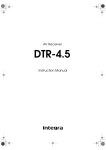
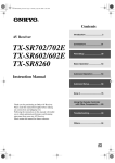
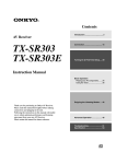
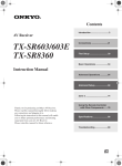
TX-8011_E.book Page 1 Friday, July 30, 2004 10:33 AM
Contents
Introduction ..................................... 2
Stereo Receiver
TX-8011
Connection .................................... 11
Playing Your Components ........... 17
Using the Tuner ............................. 19
Instruction Manual
Recording ...................................... 21
Thank you for purchasing an Onkyo Stereo Receiver.
Please read this manual thoroughly before making
connections and plugging in the unit.
Following the instructions in this manual will enable
you to obtain optimum performance and listening
enjoyment from your new Stereo Receiver.
Please retain this manual for future reference.
Troubleshooting ............................ 22
Specifications................................ 23
En
TX-8011_E.book Page 2 Friday, July 30, 2004 10:33 AM
WARNING:
TO REDUCE THE RISK OF FIRE OR ELECTRIC SHOCK,
DO NOT EXPOSE THIS APPLIANCE TO RAIN OR
MOISTURE.
CAUTION:
TO REDUCE THE RISK OF ELECTRIC SHOCK, DO NOT
REMOVE COVER (OR BACK). NO USER-SERVICEABLE
PARTS INSIDE. REFER SERVICING TO QUALIFIED
SERVICE PERSONNEL.
WARNING
AVIS
RISK OF ELECTRIC SHOCK
DO NOT OPEN
RISQUE DE CHOC ELECTRIQUE
NE PAS OUVRIR
The lightning flash with arrowhead symbol, within an equilateral
triangle, is intended to alert the user to the presence of uninsulated
“dangerous voltage” within the product’s enclosure that may be of
sufficient magnitude to constitute a risk of electric shock to persons.
The exclamation point within an equilateral triangle is intended to
alert the user to the presence of important operating and maintenance
(servicing) instructions in the literature accompanying the appliance.
Important Safeguards
1. Read Instructions—All the safety and operating
instructions should be read before the appliance is
operated.
2. Retain Instructions—The safety and operating
instructions should be retained for future reference.
3. Heed Warnings—All warnings on the appliance and
in the operating instructions should be adhered to.
4. Follow Instructions—All operating and use
instructions should be followed.
5. Cleaning—Unplug the appliance from the wall outlet before cleaning. The appliance should be cleaned
only as recommended by the manufacturer.
6. Attachments—Do not use attachments not recommended by the appliance manufacturer as they may
cause hazards.
7. Water and Moisture—Do not use the appliance
near water –for example, near a bath tub, wash bowl,
kitchen sink, or laundry tub; in a wet basement; or
near a swimming pool; and the like.
8. Accessories—Do not place
PORTABLE CART WARNING
the appliance on an unstable
cart, stand, tripod, bracket,
or table. The appliance may
fall, causing serious injury
to a child or adult, and seriS3125A
ous damage to the appliance. Use only with a cart,
stand, tripod, bracket, or table recommended by the
manufacturer, or sold with the appliance. Any mounting of the appliance should follow the manufacturer’s
instructions, and should use a mounting accessory
recommended by the manufacturer.
9. An appliance and cart combination should be moved
with care. Quick stops, excessive force, and uneven
surfaces may cause the appliance and cart combination to overturn.
10. Ventilation—Slots and openings in the cabinet are
provided for ventilation and to ensure reliable operation of the appliance and to protect it from overheating,
and these openings must not be blocked or covered.
The openings should never be blocked by placing the
appliance on a bed, sofa, rug, or other similar surface.
The appliance should not be placed in a built-in installation such as a bookcase or rack unless proper ventilation is provided. There should be free space of at least
8 in. (20 cm) and an opening behind the appliance.
2
11. Power Sources—The appliance should be operated
only from the type of power source indicated on the
marking label. If you are not sure of the type of
power supply to your home, consult your appliance
dealer or local power company.
12. Grounding or Polarization—The appliance may
be equipped with a polarized alternating current line
plug (a plug having one blade wider than the other).
This plug will fit into the power outlet only one way.
This is a safety feature. If you are unable to insert the
plug fully into the outlet, try reversing the plug. If the
plug should still fail to fit, contact your electrician to
replace your obsolete outlet. Do not defeat the safety
purpose of the polarized plug.
13. Power Cord Protection—Power-supply cords
should be routed so that they are not likely to be
walked on or pinched by items placed upon or
against them, paying particular attention to cords at
plugs, convenience receptacles, and the point where
they exit from the appliance.
14. Outdoor Antenna Grounding—If an outside
antenna or cable system is connected to the appliance, be sure the antenna or cable system is grounded
so as to provide some protection against voltage
surges and built-up static charges. Article 810 of the
National Electrical Code, ANSI/NFPA 70, provides
information with regard to proper grounding of the
mast and supporting structure, grounding of the leadin wire to an antenna-discharge unit, size of grounding conductors, location of antenna-discharge unit,
connection to grounding electrodes, and requirements for the grounding electrode. See Figure 1.
15. Lightning—For added protection for the appliance
during a lightning storm, or when it is left unattended
and unused for long periods of time, unplug it from
the wall outlet and disconnect the antenna or cable
system. This will prevent damage to the appliance
due to lightning and power-line surges.
16. Power Lines—An outside antenna system should
not be located in the vicinity of overhead power lines
or other electric light or power circuits, or where it
can fall into such power lines or circuits. When
installing an outside antenna system, extreme care
should be taken to keep from touching such power
lines or circuits as contact with them might be fatal.
TX-8011_E.book Page 3 Friday, July 30, 2004 10:33 AM
Important Safeguards—Continued
17. Overloading—Do not overload wall outlets, extension cords, or integral convenience receptacles as
this can result in a risk of fire or electric shock.
18. Object and Liquid Entry—Never push objects of
any kind into the appliance through openings as they
may touch dangerous voltage points or short-out
parts that could result in a fire or electric shock.
Never spill liquid of any kind on the appliance.
19. Servicing—Do not attempt to service the appliance
yourself as opening or removing covers may expose
you to dangerous voltage or other hazards. Refer all
servicing to qualified service personnel.
20. Damage Requiring Service—Unplug the appliance
from the wall outlet and refer servicing to qualified
service personnel under the following conditions:
A. When the power-supply cord or plug is damaged,
B. If liquid has been spilled, or objects have fallen into
the appliance,
C. If the appliance has been exposed to rain or water,
D. If the appliance does not operate normally by following the operating instructions. Adjust only those controls that are covered by the operating instructions as
an improper adjustment of other controls may result
in damage and will often require extensive work by
a qualified technician to restore the appliance to its
normal operation,
E. If the appliance has been dropped or damaged in any
way, and
F. When the appliance exhibits a distinct change in performance – this indicates a need for service.
21. Replacement Parts—When replacement parts are
required, be sure the service technician has used
replacement parts specified by the manufacturer or
have the same characteristics as the original part.
Unauthorized substitutions may result in fire, electric shock, or other hazards.
22. Safety Check—Upon completion of any service or
repairs to the appliance, ask the service technician to
perform safety checks to determine that the appliance is in proper operation condition.
23. Wall or Ceiling Mounting—The appliance should
be mounted to a wall or ceiling only as recommended by the manufacturer.
24. Heat—The appliance should be situated away from
heat sources such as radiators, heat registers, stoves,
or other appliances (including amplifiers) that produce heat.
25. Liquid Hazards—The appliance should not be
exposed to dripping or splashing and no objects
filled with liquids, such as vases should be placed on
the appliance.
FIGURE 1:
EXAMPLE OF ANTENNA GROUNDING AS PER
NATIONAL ELECTRICAL CODE, ANSI/NFPA 70
ANTENNA
LEAD IN
WIRE
GROUND
CLAMP
ANTENNA
DISCHARGE UNIT
(NEC SECTION 810-20)
ELECTRIC
SERVICE
EQUIPMENT
GROUNDING CONDUCTORS
(NEC SECTION 810-21)
GROUND CLAMPS
NEC – NATIONAL ELECTRICAL CODE
S2898A
POWER SERVICE GROUNDING
ELECTRODE SYSTEM
(NEC ART 250, PART H)
3
TX-8011_E.book Page 4 Friday, July 30, 2004 10:33 AM
Precautions
1. Recording Copyright—Unless it’s for personal use
only, recording copyrighted material is illegal without the permission of the copyright holder.
2. AC Fuse—The AC fuse inside the TX-8011
Receiver is not user-serviceable. If you cannot turn
on the TX-8011 Receiver, contact your Onkyo
dealer.
3. Care—Occasionally you should dust the TX-8011
Receiver all over with a soft cloth. For stubborn
stains, use a soft cloth dampened with a weak solution of mild detergent and water. Dry the TX-8011
Receiver immediately afterwards with a clean cloth.
Don’t use abrasive cloths, thinners, alcohol, or other
chemical solvents, because they may damage the
finish or remove the panel lettering.
4. Power
WARNING
BEFORE PLUGGING IN THE UNIT FOR THE
FIRST TIME, READ THE FOLLOWING SECTION CAREFULLY.
AC outlet voltages vary from country to country.
Make sure that the voltage in your area meets the
voltage requirements printed on the TX-8011
Receiver’s rear panel (e.g., AC 230 V, 50 Hz or AC
120 V, 60 Hz).
Setting the [STANDBY/ON] switch to STANDBY
does not fully shutdown the TX-8011 Receiver. If
you do not intend to use the TX-8011 Receiver for
an extended period, remove the power cord from the
AC outlet.
Memory backup
The TX-8011 uses a battery-less memory backup system in order to retain radio presets and other settings
when it’s unplugged or in the case of a power failure.
Although no batteries are required, the TX-8011
Receiver must be plugged into an AC outlet in order to
charge the backup system.
Once it has been charged, the TX-8011 Receiver will
retain the settings for several weeks, although this
depends on the environment and will be shorter in
humid climates.
For U.S. models
Note to CATV system installer:
This reminder is provided to call the CATV system
installer's attention to Section 820-40 of the NEC which
provides guideline for proper grounding and, in particular, specified that the cable ground shall be connected to
the grounding system of the building, as close to the
point of cable entry as practical.
FCC Information for User
CAUTION:
The user changes or modifications not expressly
approved by the party responsible for compliance could
void the user’s authority to operate the equipment.
NOTE:
This equipment has been tested and found to comply
with the limits for a Class B digital device, pursuant to
Part 15 of the FCC Rules. These limits are designed to
provide reasonable protection against harmful interference in a residential installation.
This equipment generates, uses and can radiate radio
frequency energy and, if not installed and used in accordance with the instructions, may cause harmful interference to radio communications. However, there is no
guarantee that interference will not occur in a particular
installation. If this equipment does cause harmful interference to radio or television reception, which can be
determined by turning the equipment off and on, the
user is encouraged to try to correct the interference by
one or more of the following measures:
• Reorient or relocate the receiving antenna.
• Increase the separation between the equipment and
receiver.
• Connect the equipment into an outlet on a circuit different from that to which the receiver is connected.
• Consult the dealer or an experienced radio/TV technician for help.
For Canadian models
For models having a power cord with a polarized plug:
CAUTION: TO PREVENT ELECTRIC SHOCK,
MATCH WIDE BLADE OF PLUG TO WIDE SLOT,
FULLY INSERT.
Modèle pour les Canadien
Sur les modèles dont la fiche est polarisee:
ATTENTION: POUR ÉVITER LES CHOCS ÉLECTRIQUES, INTRODUIRE LA LAME LA PLUS
LARGE DE LA FICHE DANS LA BORNE CORRESPONDANTE DE LA PRISE ET POUSSER
JUSQU’AU FOND.
4
TX-8011_E.book Page 5 Friday, July 30, 2004 10:33 AM
Features
Contents
• 50 W/ch min. RMS at 8 ohms, both channels driven
from 20 Hz to 20 kHz, with no more than 0.08% THD.
• Discrete output stage circuits for true high-current,
low-impedance drive.
• Expensive, high-quality parts, such as high-power
transistors, an oversized power transformer, and heavy
duty extruded heatsink, make it possible to accurately
and effortlessly drive 4-ohm speakers.
• 4 audio inputs
• A/B speaker selectors and outputs
• Cassette tape dubbing capability
• 30 FM/AM radio presets
• Preset scan tuning
• 3 radio preset groups (10 presets per group)
• Direct access tuning
• Motorized, precision volume control
• Headphone jack
• Audio mute, sleep timer (via remote)
• Battery-free memory backup
•
compatible remote control
Important Safeguards........................................ 2
Supplied Accessories
Make sure you have the following accessories:
Remote controller (RC-330S) & two batteries (AA/R6)
Indoor FM antenna
AM loop antenna
* In catalogs and on packaging, the letter added to the end of
the product name indicates the color of the TX-8011. Specifications and operation are the same regardless of color.
Precautions ........................................................ 4
Features.............................................................. 5
Supplied Accessories ....................................... 5
Contents ............................................................. 5
Front & Rear Panels .......................................... 6
Front Panel........................................................ 6
Display............................................................... 7
Rear Panel ........................................................ 8
Remote Controller ............................................. 9
Installing the Batteries ..................................... 10
Using the Remote Controller ........................... 10
Connections ..................................................... 11
Connecting Speakers ...................................... 11
Connecting the Supplied FM & AM Indoor
Antennas ......................................................... 12
Connecting an Outdoor FM Antenna............... 13
Connecting an Outdoor AM Antenna .............. 13
Connecting a CD Player.................................. 14
Connecting a Cassette Recorder .................... 14
Connecting a Turntable ................................... 14
Connecting
Components ......................... 15
Connecting the Power Cord of Another
Component...................................................... 15
Connecting the Power Cord ............................ 16
Turning On the TX-8011.................................. 16
Playing Your Components.............................. 17
Selecting the Source Component.................... 17
Using a Graphic Equalizer............................... 17
Adjusting the Bass, Treble & Balance ............. 17
Muting the TX-8011......................................... 17
Using the Sleep Timer..................................... 18
Using Headphones.......................................... 18
Using the Tuner ............................................... 19
Listening to the Radio...................................... 19
Tuning into Radio Stations .............................. 19
Presetting Radio Stations................................ 20
Selecting Presets ............................................ 20
Deleting Presets .............................................. 20
Recording ......................................................... 21
Recording the Input Source............................. 21
Tape-to-tape Dubbing ..................................... 21
Monitoring While Recording ............................ 21
Troubleshooting .............................................. 22
Power .............................................................. 22
Audio ............................................................... 22
Tuner ............................................................... 22
Remote Controller ........................................... 22
Specifications .................................................. 23
5
TX-8011_E.book Page 6 Friday, July 30, 2004 10:33 AM
Front & Rear Panels
Front Panel
2 34
1
M
N
5
6
O
For detailed information, refer to the pages in
parentheses.
A STANDBY/ON button (16)
This button is used to set the TX-8011 to On or
Standby.
B STANDBY indicator (16)
This indicator lights up when the TX-8011 is in
Standby mode, and it flashes while a signal is being
received from the remote controller.
C Remote control sensor (10)
This sensor receives control signals from the remote
controller.
D TUNING [ ]/[ ] buttons (19)
These buttons are used to tune into radio stations.
E DIRECT TUNING button (19)
This button is used to select a station by entering the
frequency.
F Display
See “Display” on page 7 for more information.
G MEMORY button (20)
This button is used to preset radio stations.
H FM MODE button (20)
This button is used to select the FM radio Auto and
Mono modes.
I GROUP button (20)
This button is used to select the radio preset groups.
J Number buttons (20)
These buttons are used to select preset radio stations, and to select stations by frequency.
K SCAN button (20)
This button is used to scan preset radio stations.
6
789
P
J
K
L
Q
R
S
L VOLUME control (17)
M
N
O
P
Q
R
S
This control is used to set the volume of the
TX-8011.
PHONES jack (18)
This 1/4-inch phone jack is for connecting a standard pair of stereo headphones.
SPEAKERS A & B buttons (17)
These buttons are used to turn speaker sets A and B
on and off.
TAPE 2 MONITOR button (17, 21)
This button is used to select the component connected to the TAPE 2 IN jacks, or a graphic equalizer connected to the TAPE 2 IN/OUT jacks.
Regardless of which input source is selected, the
component connected to the TAPE 2 IN jacks will
be heard when TAPE 2 indicator lights up.
Input selector buttons (17, 21)
These buttons are used to select the input sources.
BASS control (17)
This control is used to adjust the level of bass
sounds.
TREBLE control (17)
This control is used to adjust the level of treble
sounds.
BALANCE control (17)
This control is used to adjust the left and right balance.
TX-8011_E.book Page 7 Friday, July 30, 2004 10:33 AM
Front & Rear Panels—Continued
Display
1
23
STEREO
MODE
4
5
SPEAKERS A B
T-2 MONITOR
AUDIO MUTE
6 78
FM MUTE
ON OFF
TUNED
STEREO
MEMORY
9J
GROUP
A B C
SLEEP
AUTO
kHz
MHz
MONO
CH MIN
K
A STEREO MODE AUTO/FM MUTE ON
B
C
D
E
F
indicators (19)
These indicators light up when the tuner is tuned to
an FM station and Stereo mode is selected.
STEREO MODE MONO/FM MUTE OFF
indicators (19)
These indicators light up when the tuner is tuned to
an FM station and Mono mode is selected.
T-2 MONITOR indicator (17, 19)
This indicator lights up when TAPE 2 is selected.
Regardless of which input source is selected, the
component connected to the TAPE 2 IN jacks will
be heard when this indicator lights up.
SPEAKERS A B indicators (17)
These indicators show which speakers are on or off.
AUDIO MUTE indicator (17)
This indicator flashes when the TX-8011 is muted.
TUNED
indicator (19)
This indicator lights up when the TX-8011 is tuned
into a radio station.
G STEREO indicator (19)
H
I
J
K
This indicator lights up when the tuner is tuned to a
stereo FM station.
MEMORY indicator (20)
This indicator lights up when presetting radio stations.
GROUP A B C indicators
These indicators show which radio preset group is
selected.
SLEEP indicator (18)
This indicator lights up when the Sleep function has
been set.
Message area
This area of the display shows various information
about the currently selected source.
7
TX-8011_E.book Page 8 Friday, July 30, 2004 10:33 AM
Front & Rear Panels—Continued
Rear Panel
1
3
2
5
4
6
AM
REMOTE
CONTROL
ANTENNA
GND
FM 75
SPEAKERS
R
IN
IN
OUT
IN
OUT
L
L
AC OUTLET
IN
A
A
B
B
R
R
PHONO
CD
78
TAPE 1
TAPE 2
C
D
E
F
8
J
9
A Grounding screw (14)
B
AC 120V 60Hz
SWITCHED
120W 1A MAX.
L
This screw is for connecting a turntable’s ground
wire.
AM ANTENNA (12, 13)
These push terminals are for connecting an AM
antenna.
FM ANTENNA (12, 13)
This socket is for connecting an FM antenna.
SPEAKERS A (11)
These lever terminals are for connecting speaker set
A.
SPEAKERS B (11)
These lever terminals are for connecting speaker set
B.
(15)
These
(Remote Interactive) jacks can be connected to the
jacks on other Onkyo CD player
and cassette recorder. The TX-8011’s remote controller can then be used to control those components.
Note:
To use
, you must make an analog audio connection between the TX-8011 and the other component.
can only be used with Onkyo components.
G PHONO IN (14)
These jacks can be used to connect a turntable with
a moving-magnet cartridge.
H CD IN (14)
These jacks can be used to connect a CD player
with an analog output.
I TAPE 1, 2 IN/OUT (14)
This analog audio input and output can be used to
connect a cassette recorder, CD recorder, or other
recorder with an analog input and output. Alternatively, they could be used to connect a graphic
equalizer.
J AC OUTLET (15)
This switched AC outlet can be used to supply
power to another component.
TX-8011_E.book Page 9 Friday, July 30, 2004 10:33 AM
Remote Controller
1
TAPE-1
2
SLEEP
POWER
INPUT SELECTOR
TUNER PHONO
6
CD
TAPE-2
DECK-A
DECK-B
3
4
GROUP
TUNER
PRESET
MUTING
7
CD
5
DISC
VOLUME
8
REMOTE CONTROLLER RC-330S
A POWER button (16)
E CD (works only with Onkyo CD players
This button is used to set the TX-8011 to On or
standby.
B INPUT SELECTOR buttons (17, 19)
These buttons are used to select the input sources.
C DECK-A & DECK-B (works only with Onkyo
cassette recorder connected via
. For singlecassette recorder, use the DECK-B buttons)
Play [
] button
This button is used to start tape playback.
Reverse Play [
] button
This button is used to start reverse playback.
Rec/Pause [ ]/[ ] button
This button is used to start and pause tape recording.
Stop [ ] button
This button is used to stop tape playback.
Rewind/FF [
]/[
] buttons
The Rewind [
] button is used to start rewind.
The FF [
] button is used to start fast forward.
D TUNER (19, 20)
GROUP button
This button is used to select the radio preset groups.
PRESET [
]/[
] buttons
These buttons are used to select the radio presets.
connected via
)
Pause [ ] button
This button is used to pause CD playback.
Stop [ ] button
This button is used to stop CD playback.
Play [
] button
This button is used to start CD playback.
DISC button
This button is used to select discs on a CD changer.
Previous & Next [
]/[
] buttons
The Previous [
] button is used to select the previous track. During playback, the first press selects
the beginning of the current track. The Next [
]
button is used to select the next track.
F SLEEP button (18)
This button is used to set the Sleep function.
G MUTING button (17)
This button is used to mute the TX-8011.
H VOLUME [ ]/[ ] buttons (17)
These buttons are used to set the volume of the
TX-8011.
9
TX-8011_E.book Page 10 Friday, July 30, 2004 10:33 AM
Remote Controller—Continued
Installing the Batteries
1
Open the battery compartment, as shown.
Using the Remote Controller
To use the remote controller, point it at the TX-8011’s
remote control sensor, as shown below.
Remote control sensor
2
3
Insert the two supplied batteries (AA/R6)
in accordance with the polarity diagram
inside the battery compartment.
Close the battery compartment.
Notes:
• The batteries should last for about six months,
although this will vary with usage.
• If the remote controller doesn’t work reliably, try
replacing the batteries.
• Don’t mix new and old batteries or different types of
batteries.
• If you intend not to use the remote controller for a long
time, remove the batteries to prevent damage from
leakage or corrosion.
• Expired batteries should be removed as soon as possible to prevent damage from leakage or corrosion.
10
30˚
30˚
6f
.1
rox m)
p
Ap (5
t.
Notes:
• The remote controller may not work reliably if the
TX-8011 is subjected to bright light, such as direct
sunlight or inverter-type fluorescent lights. Keep this
in mind when installing.
• If another remote controller of the same type is used in
the same room, or the TX-8011 is installed close to
equipment that uses infrared rays, the remote controller may not work reliably.
• Don’t put anything, such as a book, on the remote controller, because the buttons may be pressed inadvertently, thereby draining the batteries.
• The remote controller may not work reliably if the
TX-8011 is installed in a rack behind colored glass
doors. Keep this in mind when installing.
• The remote controller will not work if there’s an
obstacle between it and the TX-8011’s remote control
sensor.
TX-8011_E.book Page 11 Friday, July 30, 2004 10:33 AM
Connections
• If you want to connect a single speaker instead of a
pair, connect it to either the left or right speaker terminals, not both.
Connecting Speakers
Before you connect your speakers, read the following:
• Disconnect the power cord from the wall outlet.
• Read the instructions supplied with your speakers.
• Pay close attention to speaker wiring polarity. In other
words, connect positive (+) terminals only to positive
(+) terminals, and negative (–) terminals only to negative (–) terminals. If you get them the wrong way
around, the sound will be out of phase and will sound
odd.
• The impedance of each speaker connected to this unit
must be no lower than 4 ohms. If you’re using only
speakers A or speakers B, the minimum speaker
impedance is 4 ohms. If you’re using both speakers A
and speaker B, the minimum speaker impedance is 8
ohms. If you use speakers with a lower impedance,
and use the amplifier at high volume levels for a long
period of time, the built-in protection circuit may be
activated.
• Unnecessarily long or very thin speaker cables may
affect the sound quality and should be avoided.
• Be careful not to short the positive
NO!
and negative connections. Doing so
may damage the TX-8011.
• Don’t connect more than one cable
to each speaker terminal. Doing so
may damage the TX-8011.
NO!
R
L
A
A
NO!
R
L
A
A
1
Strip 3/8" (10 mm) of
insulation from the
ends of the speaker
cables, and twist the
bare wires tightly.
2
Push the lever to open the
hole, insert the bare wire
into the hole, and then
push the lever again to
close the hole, thereby
securing the wire.
A
B
3/8" (10 mm)
Maker sure that the speaker connectors are gripping the
bare wires, not the insulation.
The following illustration shows which speakers should be connected to which terminals.
Speaker set A
Right
speaker
Left
speaker
SPEAKERS
R
L
AM
REMOTE
CONTROL
A
A
B
B
ANTENNA
GND
FM 75
SPEAKERS
R
IN
IN
OUT
IN
OUT
AC OUTLET
IN
L
L
R
R
PHONO
CD
TAPE 1
L
A
A
B
B
AC 120V 60Hz
SWITCHED
120W 1A MAX.
TAPE 2
CAUTION:
SPEAKER IMPEDANCE A or B: 4 ohms min./speaker
A + B: 8 ohms min./speaker
Right
speaker
Left
speaker
Speaker set B
11
TX-8011_E.book Page 12 Friday, July 30, 2004 10:33 AM
Connections—Continued
Connecting the Supplied FM & AM Indoor Antennas
ANTENNA
AM
REMOTE
CONTROL
ANTENNA
GND
FM 75
SPEAKERS
R
IN
IN
OUT
IN
OUT
L
L
AC OUTLET
IN
A
A
B
B
L
R
AC 120V 60Hz
SWITCHED
120W 1A MAX.
R
PHONO
CD
TAPE 1
TAPE 2
Adjusting the Position of the FM Indoor Antenna
The FM indoor antenna is for indoor use only. Extend the antenna fully and point it in various directions to find the best
reception. Secure it in that position with thumbtacks or something similar.
If the reception is not very good with the supplied FM indoor antenna, use an outdoor antenna.
1 Strip the insulation from
the end of the wire.
AM
2 Fully insert the bare wire.
ANTENNA
GND
FM 75
Adjusting the Position of the AM Indoor Antenna
The AM loop antenna is for indoor use only. Position it to obtain the best radio reception. Put it as far away as possible
from the TX-8011, your TV, speaker cables, and power cords.
If the reception is not very good with the supplied AM loop antenna alone, use an outdoor AM antenna as well.
Note:
Connect both wires of the AM loop antenna to the AM push terminals, as shown. (The antenna’s wires are not polarity
sensitive, so they can be connected either way around).
Rotate the outer
frame of the antenna.
Insert the tab
into the hole.
Extend the
antenna cord.
AM indoor antenna
Push the lever.
Insert the wire
into the hole.
Release the lever to
secure the wire.
AM
ANTENNA
GND
FM 75
12
TX-8011_E.book Page 13 Friday, July 30, 2004 10:33 AM
Connections—Continued
Connecting an Outdoor FM Antenna
Connecting an Outdoor AM Antenna
If you cannot achieve good reception with the supplied
indoor FM antenna, try a commercially available outdoor FM antenna instead.
If good reception cannot be achieved using the supplied
AM loop antenna, an outdoor AM antenna can be used
in addition to the loop antenna, as shown.
Outdoor antenna
FM 75
Insulated antenna cable
AM loop antenna
Notes:
• Outdoor FM antennas work best outside, but usable
results can sometimes be obtained when installed in an
attic or loft.
• For best results, install the outdoor FM antenna well
away from tall buildings, preferably with a clear line
of sight to your local FM transmitter.
• Outdoor antenna should be located away from possible
noise sources, such as neon signs, busy roads, etc.
• For safety reasons, outdoor antenna should be situated
well away from power lines and other high-voltage
equipment.
• Outdoor antenna must be grounded in accordance with
local regulations to prevent electrical shock hazards.
AM
Outdoor AM antennas work best when installed outside
horizontally, but good results can sometimes be
obtained indoors by mounting the antenna horizontally
above a window. Note that the AM loop antenna should
be left connected.
Outdoor antenna must be grounded in accordance with
local regulations to prevent electrical shock hazards.
Using a TV/FM Antenna Splitter
It’s best not to use the same antenna for both FM and
TV reception, as this can cause interference problems. If
circumstances demand it, use a TV/FM antenna splitter,
as shown.
TV/FM antenna
splitter
To TX-8011
To TV (or VCR)
13
TX-8011_E.book Page 14 Friday, July 30, 2004 10:33 AM
Connections—Continued
TAPE 2
Connecting a CD Player
Use an RCA audio cable to connect the TX-8011’s CD
IN L/R jacks to the analog audio output jacks on your
CD player, as shown.
AM
IN
ANTENNA
GND
FM 75
SPEAKE
R
IN
OUT
IN
IN
OUT
IN
A
L
L
R
R
B
PHONO
CD
TAPE 1
Use an RCA audio cable to connect the TX-8011’s
TAPE 2 IN L/R jacks to the cassette recorder’s output
jacks, and use another analog audio cable to connect the
TX-8011’s TAPE 2 OUT L/R jacks to the cassette
recorder’s input jacks, as shown.
Connecting your 3-head tape recorder to the TAPE 2
IN/OUT jacks, and pressing the [TAPE 2 MONITOR]
button allows real-time monitoring while recording.
Tip:
• Alternatively, you could connect a graphic equalizer to
the TAPE 2 IN/OUT jacks.
TAPE 2
Connecting a Turntable
OUT
CD player
Connecting a Cassette Recorder
TAPE 1
Use an RCA audio cable to connect the TX-8011’s
TAPE 1 IN L/R jacks to the cassette recorder’s output
jacks, and use another audio cable to connect the
TX-8011’s TAPE 1 OUT L/R jacks to the cassette
recorder’s input jacks, as shown.
Tip:
• You can connect other types of recorders (CD
recorder, etc) to the TAPE 2 IN/OUT jacks.
The TX-8011’s PHONO IN L/R jacks are for use with
moving magnet (MM) type cartridges. Use an RCA
audio cable to connect the TX-8011’s PHONO IN L/R
jacks to the audio output jacks on your turntable, as
shown.
Notes:
• If your turntable has a ground wire, connect it to the
GND screw on the TX-8011. With some turntables,
connecting the ground wire may cause hum, in which
case it should be disconnected.
• If your turntable has a moving coil (MC) type cartridge, you’ll need a commercially available MC head
amp. Connect your turntable to the head amp, and
connect the head amp to the TX-8011’s PHONO IN L/
R jacks.
• You can also use a phono equalizer to connect a turntable with an MC-type cartridge. In this case, see the
phono equalizer’s manual for details.
AM
OUT
IN
IN
ANTENNA
AM
L
GND
FM 75
SPEAKERS
R
ANTENNA
L
GND
IN
OUT
IN
IN
OUT
L
IN
A
A
B
B
R
FM 75
SPEAKERS
L
R
R
TAPE 1
R
IN
IN
OUT
IN
OUT
L
PHONO
CD
TAPE 1
PHONO
IN
L
B
TAPE 2
R
R
PHONO
CD
TAPE 1
TAPE 2
GND
REC
(IN)
Cassette recorder
L
PLAY
(OUT)
L
AUDIO
OUTPUT
L
/
R
R
R
14
A
L
TX-8011_E.book Page 15 Friday, July 30, 2004 10:33 AM
Connections—Continued
Connecting
Components
With
(Remote Interactive) you can control your
-compatible Onkyo CD player and cassette recorder
with the TX-8011’s remote controller, and use the following special
functions:
Direct Change
When playback is started on a component connected via
, the TX-8011 automatically selects that component
as the input source.
Connecting the Power Cord of
Another Component
The TX-8011 has a switched AC outlet on its rear panel
that can be used to connect the power cord of another
component that you intend to use with the TX-8011.
These components can then be left turned on so that they
turn on and off as and when the TX-8011 is turned on
and set to Standby.
AM
IN
REMOTE
CONTROL
ANTENNA
GND
FM 75
IN
OUT
IN
OUT
L
AC 120V 60Hz
SWITCHED
120W 1A MAX.
L
AC OUTLET
IN
A
A
B
B
AC 120V 60Hz
SWITCHED
120W 1A MAX.
L
R
AC OUTLET
REMOTE
CONTROL
SPEAKERS
R
IN
R
PHONO
CD
TAPE 1
AC OUTLET
TAPE 2
AC 120V 60Hz
SWITCHED
120W 1A MAX.
TAPE 1
IN
REMOTE
CONTROL
CD
AUDIO
OUTPUT
e.g., CD player
L
R
AUDIO
OUTPUT
Caution:
• Make sure that the capacity of the component that you
connect to the AC OUTLET does not exceed the stated
capacity (120 W).
e.g., cassette recorder
L
/
R
Notes:
• Push plugs in all the way to make good connections.
• Use only
cables for
connections. An
cable is not included with the TX-8011.
• Some components have two
jacks, you can connect either one to the TX-8011. The other is for connecting additional
-compatible components.
• Connect the TX-8011’s
jacks to only Onkyo components. Connecting to other manufacturer’s components may cause them to malfunction.
• Some components may not support all
functions.
Refer to the manuals supplied with your components.
• To use
, you must make an analog audio connection between the TX-8011 and the other component.
15
TX-8011_E.book Page 16 Friday, July 30, 2004 10:33 AM
Connections—Continued
Connecting the Power Cord
Notes:
• Before connecting the power cord, connect all of your speakers and components.
• Turning on the TX-8011 may cause a momentary power surge that might interfere with other electrical equipment on
the same circuit. If this is a problem, plug the TX-8011 into a different branch circuit.
Turning On the TX-8011
STANDBY/ON
POWER
SLEEP
POWER
TAPE-1
INPUT SELECTOR
TUNER PHONO
CD
TAPE-2
DECK-A
GROUP
TUNER
PRESET
DECK-B
MUTING
CD
DISC
VOLUME
REMOTE CONTROLLER RC-330S
Remote
controller
POWER
16
Press the [STANDBY/ON] button. Alternatively, press the remote controller’s [POWER]
button.
The TX-8011 comes on, the display lights up, and the STANDBY indicator goes off.
To turn off the TX-8011, press the [STANDBY/ON] button, or the remote controller’s [POWER] button. The TX-8011 will enter Standby mode. To prevent any loud surprises the next time you turn on
the TX-8011, always turn down the volume before you turn it off.
TX-8011_E.book Page 17 Friday, July 30, 2004 10:33 AM
Playing Your Components
This chapter explains how to use the TX-8011 with your
other components.
TUNING
SPEAKERS A/B
VOLUME
Input selector
Using a Graphic Equalizer
You can use a graphic equalizer by connecting it to the
TAPE 2 IN/OUT jacks and selecting TAPE 2.
1
Press the [TAPE 2 MONITOR] button to select TAPE 2.
The T-2 MONITOR indicator lights
up.
2
Start playback on the selected
component.
See the graphic equalizer’s manual for
details.
BASS
TREBLE
TAPE 2 MONITOR
BALANCE
Adjusting the Bass, Treble & Balance
Selecting the Source Component
1
You can adjust the bass, treble, and balance.
Press an input selector button to
select the component that you
want to play.
The name of the selected source
appears on the display, as shown.
Bass
You can boost or cut low-frequency
sounds output by the speakers. Turn
clockwise to boost; counterclockwise
to cut.
Treble
You can boost or cut high-frequency
sounds output by the speakers. Turn
clockwise to boost; counterclockwise
to cut.
A & B speakers indicators
SPEAKERS A B
Balance
Selected input source
2
Use the SPEAKERS [A] or [B]
button to select the speaker set
that you want to use.
The SPEAKERS A and B indicators
show which speakers are on or off.
Note:
If both speaker indicators are off, no
sound will come from speakers.
3
Start playback on the selected
component.
4
To adjust the volume, use the
VOLUME control, or the remote
controller’s VOLUME buttons.
You can adjust the left and right balance of the speakers and headphones. Turn clockwise to increase the
output from the right channel; counterclockwise to increase the output from
the left channel.
Muting the TX-8011
You can temporarily mute the TX-8011.
1
MUTING
Press the remote controller’s
[MUTING] button.
The output is muted and the AUDIO
MUTE indicator flashes on the display,
as shown.
AUDIO MUTE
To unmute the TX-8011, press the remote controller’s
[MUTING] button again. The output is unmuted and the
AUDIO MUTE indicator goes off.
Muting is cancelled when the TX-8011 is set to Standby.
17
TX-8011_E.book Page 18 Friday, July 30, 2004 10:33 AM
Playing Your Components—Continued
Using the Sleep Timer
With the sleep timer, you can set the TX-8011 so that it
automatically turns off after a specified period.
1
SLEEP
Press the remote controller’s
[SLEEP] button repeatedly to
select the required sleep time.
You can set the sleep time from 90 to
10 minutes in 10-minute steps.
The SLEEP indicator appears on the
display when the sleep timer has been
set, as shown. The specified sleep time
appears on the display for about five
seconds, then the previous display
reappears.
SLEEP indicator
SLEEP
MIN
To cancel the sleep timer, press the remote controller’s
[SLEEP] button repeatedly until the SLEEP indicator
disappears.
To check the remaining sleep time, press the remote
controller’s [SLEEP] button. Note that if you press the
[SLEEP] button while the sleep time is being displayed,
you’ll shorten the sleep time by 10 minutes.
Using Headphones
You can connect a pair of stereo headphones (1/4-inch
phone plug) to the TX-8011’s PHONES jack as shown.
Notes:
• Always turn down the volume before connecting your
headphones.
• The speakers are not automatically muted when the
headphones are connected, but they can be turned off
with the SPEAKERS A and B buttons.
18
TX-8011_E.book Page 19 Friday, July 30, 2004 10:33 AM
Using the Tuner
With the built-in tuner, you can enjoy AM and FM radio
stations, and you can store your favorite stations as presets for quick selection.
TUNING
Manual Tuning Mode
1
Number
MEMORY
VOLUME
Press the TUNING Up or Down
[ ]/[ ] button.
Press the buttons repeatedly to change
the frequency one step at a time.
The FM frequency changes in 0.1 MHz steps; 10 kHz
steps for AM.
Direct Tuning Mode
DIRECT TUNING
Press the [DIRECT TUNING] button.
“_ _ ” will flash for 16 seconds on the
display.
2
While the underscore characters
are flashing, use the number buttons to enter the frequency.
For example, to enter 88.1 MHz, press
[8], [8], [1].
GROUP
FM/AM
SCAN
Listening to the Radio
1
1
Press the [FM] or [AM] button.
or
Press the remote controller’s
INPUT SELECTOR [TUNER] button (This will select the last station selected. You cannot switch
between AM and FM with the
remote controller.)
In this example, FM has been selected.
FM MUTE
ON
MHz
Band
CH
Frequency
Tuning into weak FM stations
If you tune in a stereo FM station, the STEREO indicator
will appear if the signal is strong enough. If the signal is
weak, it may not be possible to tune into the station. In
this case, press the [FM MODE] button. The FM MUTE
OFF indicator will appear, the station will be in mono,
and there may be some interstation noise.
Tuning into Radio Stations
When tuned into a stereo FM station, the
TUNED
and STEREO indicators appear on the
display, as shown.
When tuned into an AM station, only the
TUNED
indicator appears.
FM MUTE
ON
TUNED
STEREO
MHz
CH
Auto Tuning Mode (FM only)
1
Press and hold the TUNING Up or
Down [ ]/[ ] button for more
than 0.5 seconds.
Searching stops when a station is
found.
19
TX-8011_E.book Page 20 Friday, July 30, 2004 10:33 AM
Using the Tuner—Continued
Presetting Radio Stations
Deleting Presets
You can store up to 30 of your favorite radio stations as
presets, 10 in each group (A, B, C).
1
Tune into the station that you
want to store as a preset.
2
Press the [MEMORY] button.
The MEMORY indicator appears.
MEMORY
CH
MHz
3
While the MEMORY indicator is
displayed (about eight seconds),
press the [GROUP] button
repeatedly to select a group.
Groups are selected in the following
order:
A → B → C → A...
MEMORY
MHz
4
GROUP
A
GROUP
B
CH
Use the number button to select
a preset number.
To choose preset #10, press the [0] button.
Repeat this procedure for all of your
favorite radio stations.
Selecting Presets
20
1
Press the [GROUP] button
repeatedly to select a group.
2
Use the number buttons to enter
the number of the preset.
or
Press the [SCAN] button
Each preset in the group selected in
step 1 will be played for five seconds.
When you hear the station that you
want, press the [SCAN] button again.
On the remote controller, use the PRESET [
]/[
] buttons to select the
presets.
1
Select the preset that you want to
delete.
See the previous section.
2
While holding down the [MEMORY] button, press the
[FM MODE] button.
The selected preset is deleted and its
number disappears from the display.
TX-8011_E.book Page 21 Friday, July 30, 2004 10:33 AM
Recording
This chapter explains how to record the selected input
source to an audio component with recording capability,
and how to dub from one cassette recorder to another.
Recording the Input Source
The effect of a graphic equalizer connected to the TAPE
2 IN/OUT jacks will not be recorded.
1
Use the input selector buttons to
select the component that you
want to record.
• You can connect your recorder to the
TAPE 1 or TAPE 2 OUT jacks.
• The FM, AM, PHONO, and CD
input sources can be recorded via the
TAPE 1 and TAPE 2 OUT jacks
simultaneously.
• You can listen to the source during
recording, and the TX-8011’s
VOLUME, BASS, TREBLE, and
BALANCE controls have no effect
on recording.
2
Start recording on the recorder
connected to the TAPE 1 OUT
or TAPE 2 OUT jacks.
3
Start playback on the source
component.
Monitoring While Recording
Normally, the sound you hear while recording is the
sound input to the TX-8011. If you have a 3-head tape
recorder (i.e., separate erase, record, and play heads),
you can monitor the sound that’s just been recorded onto
tape while recording is in progress. This allows you to
adjust the recording level on the 3-head tape recorder
and hear the result immediately.
CD player
/
Source
input signal
1
Prepare the cassette recorders.
2
Press the [TAPE 1] button.
3
Start recording on the cassette
recorder that’s connected to the
TAPE 2 OUT jacks, and start playback on the cassette recorder
that’s connected to the TAPE 1 IN
jacks.
Signal to be
recorded
Recorded
signal
1
Press the [TAPE 2 MONITOR] button.
The T-2 MONITOR indicator appears
on the display.
2
Use the input selector buttons to
select the source that you want
to record.
3
Start recording on the 3-head
tape recorder.
See the tape recorder’s manual for
details on recording.
Tape-to-tape Dubbing
By connecting a cassette recorder to the TAPE 2 OUT
jacks, you can copy tapes from the cassette recorder
that’s connected to the TAPE 1 IN jacks.
Cassette recorder
Note:
• You cannot copy from TAPE 2 to TAPE 1.
21
TX-8011_E.book Page 22 Friday, July 30, 2004 10:33 AM
Troubleshooting
If you have any trouble using your TX-8011, look for a
solution in this section. If you can’t resolve the issue
yourself, contact your Onkyo dealer.
Power
Can’t turn on the TX-8011?
• Make sure that the power cord is properly plugged into
the wall outlet.
• Unplug the power cord from the wall outlet, wait five
seconds or more, then plug the cable in again.
The TX-8011 turns off as soon as it’s turned on?
• The amp protection circuit has been activated.
Remove the power cord from the wall outlet immediately and contact your Onkyo dealer.
Audio
There’s no sound, or it’s very quiet?
• The speakers are turned off. Turn on speakers A or
speaker B (see page 17).
• Make sure that all audio connecting plugs are pushed
in all the way (pages 11–15).
• Make sure that the inputs and outputs of all components are properly connected (page 11–15).
• Make sure that the polarity of the speaker cables is
correct and that the bare wires are in contact with
metal part of each speaker terminal (page 11)
• Make sure that the input source is properly selected
(page 17).
• If the AUDIO MUTE indicator is shown on the display, press the remote controller’s [MUTING] button
to unmute the TX-8011 (page 17).
• If your turntable has a moving coil (MC) type cartridge, you’ll need a commercially available MC head
amp (page 14).
• Make sure that none of the connecting cables are bent,
twisted, or damaged.
• No sound is heard while the T-2 MONITOR indicator
is on. Press the [TAPE 2 MONITOR] button.
Noise can be heard?
• Using cable ties to bundle audio cables with power
cords, speaker cables, and so on may degrade the
audio performance, so don’t do it.
• An audio cable may be picking up interference. Try
repositioning your cables.
• The turntable and speakers are located too close to
each other. Position them further apart.
Tuner
Reception is noisy, FM stereo reception is
noisy, or the STEREO indicator doesn’t
appear?
• Relocate your antenna.
• Move the TX-8011 away from your TV or computer.
• Press the [FM MODE] button to select FM MUTE
OFF (page 19).
• When listening to an AM station, operating the remote
controller may cause noise.
• Passing cars and airplanes can cause interference.
• Concrete walls weaken radio signals.
• If nothing improves the reception, install an outdoor
antenna.
Remote Controller
The remote controller doesn’t work?
• Make sure that the batteries are installed with the correct polarity (page 10).
• Install new batteries. Don’t mix different types of batteries, or old and new batteries (page 10).
• Make sure that the remote controller is not too far
away from the TX-8011, and that there’s no obstruction between the remote controller and the TX-8011’s
remote control sensor (page 10).
Make sure that the TX-8011 is not subjected to
direct sunlight, or inverter-type fluorescent
lights. Relocate if necessary.
• If the TX-8011 is installed in a rack or cabinet with
colored-glass doors, the remote controller may not
work reliably when the doors are closed.
• When using the remote controller to control other
components, some buttons may not work as expected.
• Make sure that the
cable and analog audio cable
are connected properly. Connecting only an
cable
won’t work (page 15).
The TX-8011 contains a microcomputer for signal processing and control functions. In very rare situations,
severe interference, noise from an external source, or
static electricity may cause it to lockup. In the unlikely
event that this happens, unplug the power cord from the
wall outlet, wait at least five seconds, and then plug it
back in again.
Onkyo is not responsible for damages (such as CD
rental fees) due to unsuccessful recordings caused by
the unit’s malfunction. Before you record important data,
make sure that the material will be recorded correctly.
Resetting the TX-8011 to its factory defaults
To reset the TX-8011 to its factory defaults, turn it on
and, while holding down the [TAPE 1] button, press the
[DIRECT TUNING] button. “CLEAR” will appear on the
display and the TX-8011 will enter Standby mode.
22
TX-8011_E.book Page 23 Friday, July 30, 2004 10:33 AM
Specifications
Amplifier Section
General
Power Output
Power Supply
AC 120 V, 60 Hz
Power Comsumption 180 W
Stand-by Power Comsumption
1.35 W
Dimensions(W x H x D)
17-1/8" x 5-7/8" x 12-11/16" inches
435 x 150 x 322 mm
Weight
16.3 lbs
7.4 kg
Analog Inputs
PHONO, CD, TAPE-1, TAPE-2/
MONITOR
Analog Outputs
TAPE-1, TAPE-2/MONI
Speaker Outputs
4(SP-A, SP-B)
Phones
1
Front L/R
50 W + 50 W
(8 Ω, 20 Hz–20 kHz, FTC)
Dynamic Power
105 W + 105 W (4 Ω)
70 W + 70 W (8 Ω)
THD (Total Harmonic Distortion)
0.08 % (Power Rated)
Damping Factor
60 (Front, 1 kHz, 8 Ω)
Input Sensitivity and Impedance
150 mV/50 kΩ (LINE)
2.5 mV/50 kΩ (PHONO MM)
Output Level and Impeadance
150 mV/2.2 kΩ (REC OUT)
Phono Overload
120 mV (MM 1 kHz 0.5 %)
Frequency Response 10 Hz–100 kHz/+1 dB –3 dB
(TONE FLAT, CD, TAPE-1,
TAPE-2/MONITOR)
Tone Control
±10 dB, 50 Hz (BASS)
±10 dB, 20 kHz (TREBLE)
SN Ratio
100 dB (LINEIHF-A)
80 dB (PHONO, IHF-A)
Speaker Impedance 4 Ω
Specifications and features are subject to change without notice.
Tuner Section
FM
Tuning Frequency Range
87.5 MHz–108.0 MHz
Usable Sensitivity
Stereo 17.2 dBf 2.0 µV(75 Ω IHF)
Mono 11.2 dBf 1.0 µV(75 Ω IHF)
S/N Ratio
Stereo 70 dB (IHF-A)
Mono 76 dB (IHF-A)
THD
Stereo 0.25 % (1kHz)
Mono 0.15 % (1kHz)
Frequency Response 30 Hz–15 kHz/±1.5 dB
Stereo Separation
45 dB ( 1kHz )
AM
Tuning Frequency Range
530 kHz–1710 kHz
Usable Sensitivity
30 µV
S/N Ratio
40 dB
THD
0.70%
23
TX-8011_E.book Page 24 Friday, July 30, 2004 10:33 AM
Sales & Product Planning Div. : 2-1, Nisshin-cho, Neyagawa-shi, OSAKA 572-8540, JAPAN
Tel: 072-831-8023 Fax: 072-831-8124
ONKYO U.S.A. CORPORATION
18 Park Way, Upper Saddle River, N.J. 07458, U.S.A.
Tel: 201-785-2600 Fax: 201-785-2650 http://www.onkyousa.com
ONKYO EUROPE ELECTRONICS GmbH
Liegnitzerstrasse 6, 82194 Groebenzell, GERMANY
Tel: +49-8142-4401-0 Fax: +49-8142-4401-555 http://www.onkyo.net
ONKYO EUROPE UK Office
Suite 1, Gregories Court, Gregories Road, Beaconsfield, Buckinghamshire, HP9 1HQ
UNITED KINGDOM Tel: +44-(0)1494-681515 Fax: +44(0)-1494-680452
ONKYO CHINA LIMITED
Units 2102-2107, Metroplaza Tower I, 223 Hing Fong Road, Kwai Chung,
N.T., HONG KONG Tel: 852-2429-3118 Fax: 852-2428-9039
HOMEPAGE
http://www.onkyo.com/
I0408-1
SN 29343912
(C) Copyright 2004 ONKYO CORPORATION Japan. All rights reserved.
24
* 2 9 3 4 3 9 1 2 *