1
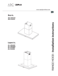
www.zephyronline.com
Venezia
Use, Care, and Installation Guide
ZVE-E30S
ZVE-E36S
ZVE-E42S
Model number:
Serial number:
MAY07.0101 © Zephyr Corporation.
www.zephyronline.com
2
3
Table of Contents
SAFETY NOTICE ..............................................
LIST OF MATERIALS .......................................
INSTALLATION
Ducting Calculation Sheet ...............................
Mounting Height and Clearance .....................
Ducting ..................................................................
Specifications .......................................................
Mounting the Hood and Duct Cover................
Ductless Recirculating ........................................
4
5
6
7
8
9
FEATURES & CONTROLS
Touch Controls & Features ................................. 10
Charcoal Filter Change Indicator ...................... 11
Metal Filter Clean Indicator ................................ 12
MAINTENANCE
Cleaning ................................................................. 13
Lights ....................................................................... 14
TROUBLE SHOOTING ...................................... 15
LIST OF ACCESSORIES/PARTS ....................... 16
1
www.zephyronline.com
Important safety Notice
READ AND SAVE THESE INSTRUCTIONS
WARNING
TO RE DUCE TH E R IS K O F FIR E O R E LE C TR IC SHOC K, DO NOT US E TH IS FAN W ITH ANY S O LID-S TATE
SP E E D C O NTRO L DEV IC E.
WARNING
TO RE DUCE TH E R IS K O F FIR E, E LE C TR IC SH O C K, O R INJU RY TO P E R SON S, O B S E RVE TH E FO LLO W ING:
a. Use this unit only in the manner intended by the manufacturer, If you have questions, contact the manufacturer.
b. Before servicing or cleaning unit, switch power off at service panel and lock the service disconnecting means to prevent power from being
switched on accidentally.
When the service disconnecting means cannot be locked, securely fasten a prominentwarning device, such as tag, to the service panel.
CAUTION
For General VentilatingUse Only. Do not Use to Exhaust Hazardous or Explosive Materials and Vapors.
Take care when using cleaning agents or detergents.Suitable for use in household cooking area.
WARNING
TO REDUC E TH E R IS K O F A RA NG E TO P GR E AS E FIR E:
a. Never leave surface units unattendedat high settings. Boilovers cause smoking and greasy spillovers that may ignite. Heat oils slowly on low
or mediumsettings.
b. Always turn hood ON when cooking at high heat or when cooking flambeing food (i.e. Crepes Suzette, Cherries Jubilee, Peppercorn
Beef Flambe)
c. Clean ventilatingfans frequently. Grease should not be allowed to accumulate on fan or filter.
d. Use proper pan size. Always use cookware appropriatefor the size of the surface element.
WARNING
TO RE DUC E TH E R IS K O F INJURY TO P ERSON S IN TH E EV E NT O F A RA NG E TO P G R E AS E FIR E, O B S E RVE TH E FO LLOW ING :
a. SM OTHE R FLA MES with a close-fitting lid, cookie sheet, or metal tray, then turn off the burner. B E CARE FUL TO P R EV E NT BUR NS.
If the flames do not go out immediately,E VAC UATE AND CALL TH E FIR E DE PARTME NT.
b. NEV E R PIC K UP A FLAMI NG PAN - You may be burned.
c. DO NOT US E WATE R, includingwet dishcloths or towels - a violentsteam explosion will result.
d. Use an extinguisher ONLY if:
1. You know you have a class AB C extinguisher, and you already know how to operate it.
2. The fire is small and contained in the area where it started.
3. The fire departmentis being called.
4. You can fight the fire with your back to an exit.
5. Based on “Kitchen Fire Sa fety Tips” published by NFPA.
WARNING
TO R E DUC E TH E R IS K O F FIR E, E LE C TR IC SHOC K O R INJURY TO PER SONS, O B S E RVE TH E FO LLOW ING :
a. Installation Work and Electrical Wiring Must be Done by Qualified Person (s) In Accordance with all Applicable Codes and Standards,
Including Fire-Rated Construction.
b. Sufficient air is needed for proper combustionand exhausting of gases through the flue (chimney) of fuel burningequipmentto prevent back
drafting. Follow the heating equipmentmanufacturer’s guideline and safety standards such as those published by the National Fire Protection
Association (NFPA), and the American S ociety for Heating, Refrigeration, and Air ConditioningEngineers (AS H R AE) and the local code authorities.
c. When cutting or drillinginto wall or ceiling, do not damage electrical wiring and other hidden utilities.
d. Ducted fans must always vent to the outdoors.
WARNING
TO REDUC E TH E R IS K O F FIR E, USE O NLY ME TAL DU C TW O R K.
CAUTION
To reduce risk of fire and to properly exhaust air, be sure to duct air outside - Do not vent exhaust air into spaces within walls or ceilings or into
attics, crawl spaces or garages.
WARNING
TO REDUCE THE RISK OF SHOCK, THIS FAN MUST BE INSTALLED WITH AN ISOLATING WALL CONTROL/SWITCH.
2
1 - Duct cover mounting bracket
1 - Packet of mounting screws w/anchors
1 - Butterfly damper
NO DUCTING IS INCLUDED
* Note: Zephyr recommends using 50LB EZ anchors if mounting hood onto drywall. These are not provided.
but are readily available of most hardware stores.
3
List of Materials
1 - Hood
2 - Metallic filters (3 - ZVE-E36, E42)
2 - Halogen light bulbs (4 - ZVE-E36, E42)
1 - Duct cover assembly (2 pieces)
1 - Hardware bag
www.zephyronline.com
Equivalent number
length x used =
Installation -
Ductwork Calculation Sheet
Duct pieces
Equivalent number
length x used =
Duct pieces
Total
Total
3 1/4” x 10”
Rect.,
straight
1 Ft.
x(
) =
Ft.
6” Round
30 Ft.
wall cap
with damper
x(
) =
Ft.
7” Round,
straight
1 Ft.
x(
) =
Ft.
6” Round,
roof cap
30 Ft.
x(
) =
Ft.
7” Round,
straight
1 Ft.
x(
) =
Ft.
6” round to
3 1/4” x 10”
rect.
transition
1 Ft.
x(
) =
Ft.
3 1/4” x 10”
Rect. 90 0
elbow
15 Ft.
x(
) =
Ft.
16 Ft.
x(
) =
Ft.
3 1/4” x 10”
Rect. 45 0
elbow
9 Ft.
x(
) =
Ft.
6” round to
3 1/4” x 10”
rect.
transition
90 0 elbow
7” Round,
90 0 elbow
15 Ft.
x(
) =
Ft.
3 1/4” x 10”
Rect. 90 0
flat elbow
24 Ft.
7” Round,
45 0 elbow
9 Ft.
x(
) =
Ft.
7” Round
30 Ft.
wall cap
with damper
x(
) =
Ft.
7” Round,
roof cap
30 Ft.
x(
) =
Ft.
7” round to
3 1/4” x 10”
rect.
transition
8 Ft.
x(
) =
Ft.
7” round to
3 1/4” x 10”
rect.
transition
90 0 elbow
15 Ft.
x(
) =
Ft.
x(
) =
Ft.
Ft.
3 1/4” x 10”
30 Ft.
Rect.
wall cap
with damper
x(
3 1/4” x 10”
Rect. to
6” round
transition
5 Ft.
x(
) =
Ft.
3 1/4” x 10”
Rect. to
6” round
transition
90 0 elbow
15 Ft.
x(
) =
Ft.
6” Round,
90 0 elbow
15 Ft.
x(
) =
Ft.
6” Round,
45 0 elbow
9 Ft.
x(
) =
Ft.
) =
Subtotal column 1 =
Ft.
Maximum Duct Length: For satisfactory air movement,
the total duct length of a 3 1/4” x 10” rectangular, 6” or 7”
diameter round ductshould not exceed 100 equivalent feet.
4
Subtotal column 2 =
Ft.
Subtotal column 1 =
Ft.
Total ductwork
Ft.
=
Maximum mount height should be no higher than 36".
min. ducted - 32 1/2”
min recirc. - 36”
max. 51”
9-27/32"
min. 28" - max. 36"
* min. 97"
** max. 123"
It is important to install the hood at the proper mounting
height. Hoods mounted too low could result in heat
damage and fire hazard; while hoods mounted too high
will be hard to reach and will loose its performance and
efficiency.
If available, also refer range manufacturer'sheight
clearance requirements and recommended hood
mounting height above range. Always check your local
codes for any differences.
*Minimum ceiling height of 97”. Hood
mounted at 28” above cooking surface.
** Maximum ceiling height of 123". Hood
mounted at 36" above cooking surface.
36"
Minimum Duct Size:
Round- 6" minimum
Rectangular- 3-1/4 x 10” minimum (requires
a 6” to 3-1/4 x 10” adapter not supplied)
DUCTING
A minimum of 6" round or 3-1/4 x 10"
rectangular duct must be used to maintain
maximum air flow efficiency.
Always use rigid type metal ducts only.
Flexible ducts could restrict air flow by up
to 50%.
DAMAGE-SHIPMENT / INSTALLATION:
• Please fully inspect unit for damage
before installation.
Use calculation worksheet to compute total
duct work.
• If the unit is damaged in shipment , return
the unit to the store in which it was bought
for repair or replacement.
ALWAYS, when possible, reduce the number or
transitions and turns. If long duct run is
required, increase duct size from 6" to 7 or 8".
If a reducer is used, install a long reducer
instead of a pancake reducer. Reduce duct size
as far away from opening as possible.
• If the unit is damaged by the customer ,
repair or replacement is the responsibility
of the customer.
If turns or transitions are required:
Install as far away from opening and as far
apart, between 2, as possible.
• If the unit is damaged by the installer
(if
other than the customer), repair of replace
ment must be made by arrangement
between customer and installer.
5
I nstallation - M ounting Height & Clearance
Minimum mount height between range top to hood bottom should be no less than 28".
Installation -
Ducting
www.zephyronline.com
WARNING FIRE HAZARD
NEVER exhaust air or terminate duct work into spaces between walls, crawl spaces, ceiling,attics or garages. All exhaust must
be ducted to the outside, unless using the recirculating option.
Use single wall rigid Metal ductwork only.
Fasten all connections with sheet metal screws and tape all joints w/ certified Silver Tape or Duct Tape.
Some Ducting Options:
side wall cap
w/ gravity dampe
side wall cap
w/ gravity damper
Soffit or crawl space
Roof Pitch w/
Flashing & Cap
air
recirculating
6
14
1.87"
0.5"
6.5"
-3/
16
”
2.78"
6"
19-11/16”
10.37"
21-21/32”
13.87"
1-19/32”
min. ducted - 32 1/2”
min. recirc. - 36”
max. - 51”
9-27/32”
30
”, 3
6”,
42
”
”
24
3/4" Elec. K.O.
ELECTRICAL - WARNING
All Electrical work must by performed by qualified electrician or person with similar technical know how
and background.
For personal safety, remove house fuse or open circuit breaker before beginning installation.
Do not use extension cord or adapter plug with this appliance.
Follow National electrical codes or prevailing local codes and ordinances.
Electrical Supply:
This appliance requires a 120V 60Hz electrical supply., and connected to an individual, properly grounded branch
circuit, protected by a 15 or 20 ampere circuit breaker or time delay fuse. Wiring must be 2 wire w/ ground. Please
refer to Electrical Diagram labeled on product.
Cable Lock:
A cable locking connector (not supplied) might
also required by local codes. Check with local
requirements and codes, purchase and install
appropriate connector if necessary.
Cable Lock
7
Installation - Specifications
8”
-5/
10
I nstallation - M ounting the Hood & Duct Cover
www.zephyronline.com
1. Measure from range top to hood bottom
(28” min) Level and mark line A.
C/L
2. Plum and mark center line.
Duct Cover Bracket
3. Mark mounting height line B. (10-3/8” from line A)
4. Mark mounting spread from C/L (9-7/16”)
9-7/16"
5. Fasten E-Z anchors to wall (see below) as marked.
B
6. Fasten screws provided onto EZ anchors, do not
fasten screws all the way.
10-3/8"
A
7. Hang hood onto screws and hand tighten (fig A).
28" min
MOUNTING THE DUCT COVER
C/L
1. Center and attach duct cover mount bracket on
wall below ceiling or soffit.
2. Mount telescopic duct covers onto hood and
extend inner duct cover and fasten to bracket.
fig. A
EZANCHORS
Tap EZ anchor tip into marked drywall locations, turn with screwdriver until seated flush.
Note:whenever possible, the hood should be secured to wall studs.
Use EZ anchors only on hollow drywall applications (minimum
drywall thickness 1/2”). If a stud or wood surface is present,
fasten screws directly into stud or plywood. For all other wall types
(concrete, brick, tiles, etc), use appropriate anchors for mounting.
8
We recommend to ALWAYS exhaust air outside of the home by employing existing or installing new duct work, if
possible. The hood is most effective and efficient as an Exhaust unit. Only when the exhaust option is not possible
should you recourse to converting the hood into a "purifying"unit.
When converted to be a "purifying" unit, a set of charcoal filters are required on top of its standard Metal Filter set.
Order according to its Part number below. The standard Metal Filters are intended to capture residue from cooking
and the optional charcoal filters help to purify fumes exhausted from cooking for re-circulation.
RECIRCULATING KIT (Required)
1. Kit includes charcoal filters and air diverter plate:
ZVE-E30S
ZVE-E36S
ZVE-E42S
Part No.
ZRC-0050
ZRC-0051
ZRC-0051
Filters in pkg.
Installation -
Hood Model:
Ductless Recirculating
Ductless recirculating is intended for applications where an exhaust duct work is not possible to be installed.
When converted, the hood functions as a "purifying" hood rather than an exhaust hood. Fumes and exhaust from
cooking is drawn and filtered by a set of optional charcoal filters. The air is then purified and re-circulated back within
the home.
2
3
3
2. Remove metal filters on hood. Clip chacoal
filters onto difuser panels.
3. Re-install metal filters.
4. Turn on filter change indicator on control
panel (refer details pg. 7)
5. Charcoal filters must be replaced after
every 120 hours of use (or approximately
every 2 to 3 months based on the average
of 1-2 hrs. of daily cooking time). The
microprocessor in the controls when set,
will elapsed and count usage time and
indicate when carbon filter replacement is
required every 120 hrs.
Charcoal Filter Dimensions:
9 in x 6.4 in
228 mm x 162 mm
Ducting
air diverter
plate
1. Install a 6" straight pipe attached to the air diverter
plate to divert air through louvers on duct cover.
6" straight pipe
wall pipe strap
9
Features & Controls - Touch Controls & Features
www.zephyronline.com
1. Blower On/Off
By pressing
, the blower is switched On and Off. When switched on, the blower starts up on speed level 3.
2. Speed Selection
The 6 speed levels are selected by presing
level selected.
to decrease and
to increase speed level. The display indicates
3. Delay Off
This is used for programmed shut down of blower and lights 15 minutes after the function is activated. Press
once,
a dot flashes in the lower right hand side of display
indicating the function is on. The hood will completely shut down
in 15 minutes.
4. Lights On/Off/Dim
Switch lights On and Off by pressing key
once. To dim lights, press and hold
for 2 seconds.
5. Advance Display Functions
Filters Clean Reminder (Metal):
After every 30 hours of use, the display will start flashing an
possible clogs.
reminding you to clean the metal filters from residue and
The standard Metal Filters are required to be cleaned frequently and as recommended in order to maintain blower
efficiency. If improperly maintained, residue from cooking will sift though filters and cause damage to hood blowers
and other sensitive components; and possibly clog duct work and create a fire hazard.
Filters Change Reminder (Charcoal, if fitted):
When your hood is installed as “Recirculating” (Ductless) unit, it is fitted with a set of Chacoal Filters to purify any
exhaust and fumes from cooking, and re-circulates the air within the home. These Charcoal Filters are required to be replaced
after every 120 hours of use. The Filter Change Reminder function in the microprocessor needs to be switched on. The
microprocessor in the controls when set, will elapsed and count usage time and indicate when charcoal filter replacement is
needed every 120 hrs.
10
Setting the Filter Change Reminder:
When Off, hold
for approx. 5 seconds.
The display will change from
(exhaust mode) to
, (purifying mode/
carbon filters used) this indicates that the
elapse timer function is switched on and
Charcoal Filters are used.
Filter Replace Indicator:
Set Mode
hold 5 secs.
Change Filters
When the display
starts flashing, the
Charcoal Filters require replacement.
display from <--> to <C>
display <C> flashes
Re-setting Function:
Once filters are replaced, with hood off,
press and hold
, the display will appear;
hold for approximately 5 seconds until
on display disappears
. The Filter
Change Reminder is now re-set and a new
120 hours elapse cycle is initiated.
To Reset
hold 5 secs.
11
display from <C> to < >
Features & Controls - Charcoal Filters Change Indicator
Filter Change Reminder (Charcoal, if fitted):
When your hood is installed as a 'Recirculating' (Ductless) unit, it is fitted with a set of Charcoal Filters to
purify exhaust and fumes from cooking, then re-circulate the air within the home.These Charcoal Filters are required
to be replaced after every 120 hours of use. The Filter Change Reminder function in the microprocessor needs to
be switched on. The microprocessor in the controls when set, will elapse and count usage time and indicate by a
flashing
when charcoal filter replacement is needed.
Features & Controls - Metal Filters Clean Indicator
www.zephyronline.com
Filter Clean Reminder (Standard Metal Filters fitted):
Whether your hood is installed as an Exhaust or Purifying unit, a set of metal filters are fitted by the factory. These Metal
Filters are intended to filter out residue from cooking. They need not be replaced on a regular basis but are required to be
kept clean. The Filter Change Reminder function in the microprocessor will automatically indicate by a flashing
when the metal filters need to be cleaned after every 30 hrs. of use. Filters can be cleaned by hand with non-abrasive soap
or in a dishwasher. Heavily soiled filters should also be soaked in grease cutting detergent such as Formula '409' or its
equivalent, prior to cleaning.
Filter Clean Reminder:
When
flashes on display, the metal
filters installed are required to be cleaned.
This will occur after every 30 hours of use.
Clean Filters
display <A> flashes
Re-setting Function:
Reset the Filter Clean Reminder timer when
filters are cleaned and re-installed (with
hood off). Press and hold
for approx.
5 seconds, the display will appear; hold for
approximately 5 seconds until
on display disappears
. The Filter Clean
Reminder function is now re-set and a new
30 hours elapse cycle is initiated.
To Reset
hold 5 secs.
12
display from <C> to < >
Clean periodically with hot soapy water and clean cotton cloth. Do not use corrosive or abrasive detergent , or steel
wool/scouring pads which will scratch and damage surface.
For heavier soil use liquid degreaser.
After cleaning, you may use non-abrasive stainless steel polish/ cleaners, to polish and buff out the stainless luster
and grain. Always scrub lightly, with clean cotton cloth, and with the grain.
Do not use any product containing chlorine bleach. Do not use “orange” cleaners.
Metal Filters
The Metal Filters fitted by the factory are intended to
filter out residue and grease from cooking. They
need not be replaced on a regular basis but are
required to be kept clean.
Filters should be cleaned after every 30 hours of
use. Use the Filter Clean Reminder function on the
controls to determine when filters require cleaning.
Remove and clean by hand or in dishwasher. Spray
degreasing detergent and leave to soak if heavily
soiled.
Dry filters and re-install before using hood.
Replacing Metal Filters
Should filters wear out due to age and prolonged
use, replace with following part number:
Hood Model:
ZVE-E30S
ZVE-E36S
ZVE-E42S
Part No.
Z0F-MO42
Z0F-MO43
Z0F-MO43
Filters in pkg.
Metal Filter Dimensions:
2
3
3
16.12 in x 9.12 in
409 mm x 232 mm
Also replace any damaged filter that has punctured
or broken mesh, bent or broken frame.
13
Maintenance - Cleaning
Surface Maintenance:
Maintenance - Lights
www.zephyronline.com
Replacing Light Bulbs
CAUTION: Light bulb becomes extremely hot when turned on. DO NOT touch bulb until switched off and cooled.
Touching hot bulbs could cause serious burns.
Make sure all power is turned off and bulbs
are not hot.
Remove by turning bulb counter clockwise.
If bulbs are difficult to turn due to prolonged
use, firmly attach a glass suction cup approx.
the diameter of the bulb or use a rubber/
latex glove and turn counter clockwise.
Replacement bulbs are available at
specialty lighting stores. Purchase type
JDR E27 50W halogen bulbs.
Or to order bulbs, please call our service
center: 888-880-8368 or online parts store:
www.zephyronline.com
14
Cause
What to do
After installation, the unit
doesn’t work?
1. The power source is not turned ON.
1. Make sure the circuit breaker and the unit’s
power is ON.
2. The power line and the cable locking connector is
not connecting properly.
2. Check the power connection with the unit is
connected properly.
3. The switch board and control board wirings
are disconnected.
3. Make sure the wirings between the switch
board and control board are connected properly.
4. The switch board or control board is
defective.
4. Change the switch board or control board.
1. The motor is defective, possible seized.
1. Change the motor.
2. The thermally protected system detects if the motor
is too hot to operate and shuts the motor down.
2. The motor will function properly after the
thermally protected system cool down.
3. Damaged condenser.
3. Change the condenser.
1. The motor is not secure in place.
1. Tighten the motor in place.
2. Damaged blower wheel.
2. Change the blower wheel.
3. The hood is not secured in place.
3. Check the installation of the hood.
1. Defective halogen bulb.
1. Change the halogen bulb.
2. The light bulb is loose.
2. Tighten the light bulb.
3. The light bulb is not making a full contact.
3. Remove the bulb and disable power to the
hood. Bend the two metal brackets inside the
bulb opening and bend them outwards to lower
the socket and make a complete contact.
1. The hood might be hanging to high from the
cook top.
1. Adjust the distance between the cook top
and the bottom of the hood within 24” and
32” range.
2. The wind from the opened windows or opened
doors in the surrounding area are affecting the
ventilation of the hood.
2. Close all the windows and doors to eliminate the
outside wind flow.
3. Blocking in the duct opening or ductwork.
3. Remove all the blocking from the duct work or
duct opening.
4. The direction of duct opening is against the wind.
4. Adjust the duct opening direction.
5. Using the wrong size of ducting.
5. Change the ducting to at least 8” or higher.
1. Metal filter is loose.
1. Change the metal filter.
Light works, but motor is
not turning.
The unit is vibrating.
The motor is working,
but the lights are not.
The hood is not venting
out properly.
Metal filter is vibrating.
15
Trouble Shooting
Issue
Part#
Light Bulb (JDR-E27)
Z0B-0011
Metallic Filters (2 pk)
Z0F-M042
Metallic Filters (3 pk)
Z0F-M043
Telescopic Back Splash 30”
Z0S-0013
Telescopic Back Splash 36”
Z0S-0016
Telescopic Back Splash 42”
Z0S-0012
Wire Spice Rack 30”
Z0R-0013
Wire Spice Rack 36”
Z0R-0016
Wire Spice Rack 42”
Z0R-0012
List of Parts and Accessories
Description
To order parts, visit us online at : www.zephyronline.com and go to the parts store.
Or call us at : 888-880-8368
16
Warranty
www.zephyronline.com
TO OBTAIN SERVICE UNDER WARRANTY
or any Service Related Questions, please call:
1-888-880-8368
Staple your receipt here.
Proof of the original purchase
date is needed to obtain service
under the warranty.
TO OBTAIN SERVICE UNDER WARRANTY: You must present proof of original purchase date.
Please keep a copy of your dated proof of purchase (sales slip) in order to obtain service under warranty.
One Year Service Repair Warranty:
For one year from date of original purchase, we will provide free of charge, service labor to repair any failed parts or
components due to manufacturing defects.
One Year Parts Warranty:
For one year from date of original purchase, we will provide free of charge, nonconsumable replacement parts or
components that failed due to manufacturing defects. Consumable parts not covered by this warranty include: Light Bulbs,
Metal and Charcoal Filters.
Who is Covered:
This warranty is extended to the original purchaser for products purchased for ordinary home use in the 48 mainland states,
Hawaii and Washington D.C. In Canada and Alaska, this warranty is Limited.
There might be costs associated with
shipping the products to our designated service locations or you might need to pay service technician's travel costs, to have
the appliance repaired in-home.
This Warranty will be Voided when:
Product damaged through negligence, misuse, abuse, accident. Improper installation and failure to follow installation instructions. When product is used commercially or other than its intended purpose. Damaged because of improper connection with
equipment of other manufacturers. Repaired or modified by anyone other than Zephyr's Authorized Agents.
What is Not Covered:
Consumable parts such as light bulbs, filters, and fuses. Services outside of service area and the labor cost incurred in
connection with the removal, shipping and reinstallation cost, nor does it cover any other contingent expenses. The natural
wear of finish, and wear due to improper maintenance, use of corrosive and abrasive cleaning products, pads, and oven
cleaner products. Chips, dents or cracks due to abuse, misuse, freight damage, or improper installation. Service trips to your
home to teach you how to use the product. Damage of product caused by accident, fire, floods or act of God.
This warranty is valid in the United States and Canada. It is non-transferable and applies only to the original purchaser and
does not extend to subsequent owners of this product. Any applicable implied waranties, including the warranty of
merchantability, are limited in duration to a period of express warranty as provided herein beginning with the date of original
purchase at retail and, no warranties, whether express or implied, shall apply to this product thereafter.
Have your product proof of purchase with date ready for warranty issues.
Or write to:
Zephyr Corporation
Service and Warranty Department
395 Mendell Street
San Francisco, CA 94124
JAN07.0101