1
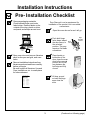
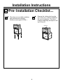
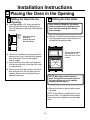
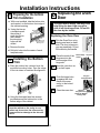
Installation
Instructions
27” Built In Wall Oven/ with
Microwave
JKP85
“If you have questions, call 800-GE-CARES or visit our website at:
www.GEAppliances.com”
Before you begin
• ATTENTION INSTALLER!!
All electric wall ovens must be hard wired
(direct wired) into an approved junction
box. A “plug and receptacle” is NOT
permitted on these products
• NOTE- This appliance must be properly
grounded.
Read these instructions carefully and completely
• IMPORTANT-Save these instructions for
local inspector’s use.
• IMPORTANT-Observe all governing
codes and ordinances.
• Note to Installer- Be sure to leave these
instructions with the consumer.
• OWNER- Keep these instructions for future
reference.
Parts Included
Materials Needed
Bottom Trim
Wire Nuts
Strain Relief
Clamp
8 flat head screws side trim
3 Pan head screws bottom trim
Junction
Box
36” of String
Tools You Will Need
1/8” Drill Bit &
Electric or
Hand Drill
Pub. No. 31-10480
229C4053P460
Phillips
Screwdriver
1
Installation Instructions
IMPORTANT SAFETY INSTRUCTIONS
Electrical
Requirements
For Your Safety
This appliance must be supplied with the
proper voltage and frequency, and connected
to an individual properly grounded branch
circuit, protected by a circuit breaker or fuse
having amperage as noted on rating plate.
(Rating Plate is located on oven side trim.)
We recommend you have the electrical wiring
and hookup of your oven connected by a
qualified electrician. After installation, have the
electrician show you where your main oven
disconnect is located.
Check with your local utilities for electrical
codes which apply in your area. Failure to wire
your oven according to governing codes could
result in a hazardous condition. If there are no
local codes, your range must be wired and
fused to meet the requirements of the National
Electrical Code, ANSI/NFPA No. 70-Latest
Edition. You can get a copy by writing:
National Fire Protection Association
Battery March Park
Quincy, MA 02269
Effective January 1, 1996, the National
Electrical Code requires that new, but not
existing, construction utilize a 4 conductor
connection to an electric range. When
installing an electric range in new construction,
follow the instructions in the section on NEW
CONSTRUCTION AND FOUR CONDUCTOR
BRANCH CIRCUIT CONNECTION.
You must use a three-wire, single-phase A.C.
208Y/120 Volt or 240/120 Volt, 60 hertz
electrical system. If you connect to aluminum
wiring, properly installed connectors approved
for use with aluminum wiring must be used.
• Be sure your oven is installed properly by
a qualified installer or service technician.
• Be sure the oven is securely installed in a
cabinet that is firmly attached to the house
structure. Weight on the oven door could
cause the oven to tip and result in injury.
Never allow anyone to climb, sit, stand or
hang on the oven door.
• Make sure the cabinets and wall coverings around the oven can withstand the
temperatures (up to 200°F.) generated by
the oven.
CAUTION: The electrical power
to the oven supply line must be
shut off while line connections
are being made. Failure to do so
could result in serious injury or
death.
2
Installation Instructions
Pre- Installation Checklist
Remove packaging materials.
Check behind hinges, and under
false bottom. Remove labels on the
outside of the door, plastic on trims
and panel, and all tape around oven.
Door Removal is not a requirement for
installation of the product, but is an added
convenience.
Open the oven door as far as it will go.
Push both hinge
locks down toward
the door frame, to
the unlocked
position. This may
require a flat blade
screwdriver.
Oven Racks
EASY
INSTA
LLAT
EASY INSTALLATION
OF
IONYOUR NEW
30"
WALL
30" WALL
OVENOF YOUR
OVEN
NEW
Broiler Pan
and Grid
Before
you
IMPORTA
begin-Rea
IMPORTA NTd these
Save
Note
NTthese
instruction
OBSERVE instruction
to InstallerOWNERBefore
you begin-Read
these instructions completely
and carefully.
s completel
ALL
Be sure
s for inspector's
NoteKeep
IMPORTANTSave these
instructions
for local
use.
GOVERNI
local
these
y and
This
to leave
inspector'
appliance ALL
IMPORTANT- OBSERVE
GOVERNING
CODES
AND
ORDIANCES.
NG
instruction
carefully.
CODES
these
s use.
Note to Installer- Be suremust
to leave these
instructions
with
the consumer.
instruction
s
AND
be for for
future
OWNER- Keep these instructionsproperly
future
reference. s withORDIANC
reference.
FOR
ES.
grounded
the
YOUR
Note- This
appliance must be properly grounded
(if applicable).
consumer
SAFETY
(if applicable
Before
.
you
instruction
begin-Rea
).
carefully. s completel d
FOR YOUR SAFETYthese
ELECTRICAL REQUIREMENTS
IMPORTA
y and
ELECTRIC
instructionNTBefore youSave
begin-Read these
AL REQUIREM
Before you begin-Read
these
IMPORTA
these
s for
Before
instructions
completely and
local
instructions
completely and
GOVERNI
NTyou
inspector'
ENTS
OBSERVE
instruction
carefully.begin-Rea
Note carefully.
NG
CODES
carefully. s completel d
to InstallerSave ALL
these s use.
these IMPORTANTIMPORTANT- Save these
these
AND
IMPORTA
instruction
instructions
local inspector's use.
Befor
y and
OWNERinstructions for local
inspector's use.
sure ORDIANC
instructionNTto leave
s with
OBSERVE
ALL ES.
Save OBSERVE ALL
for futureIMPORTANTKeep
IMPORTANTthe AND ORDIANCES. IMPORTA s for
these
these CODES
GOVERNING
consumer
Notereference. instruction
GOVERNING
localCODES AND ORDIANCES.
GOVERNI
NTThisNote to Installerinspector'
Be sure to leave
OBSERVE
properly
.
appliance
Note
s
Note
NG to Installer- Be sures to leave
Before grounded
these instructions
ALL
theseCODES
instructions
with theuse.
consumer.
must with the consumer. these to Installeryou
instruction
AND
be instructions
begin-Rea
OWNERKeep
these
(if
instruction
OWNER-Be
Keep these
instructions
applicable
OWNERsure ORDIANC
carefully. sfor
future reference.
d these
completel
to leave
s with
for future
reference.
ES.
).
for future Keep
IMPORTA
the
Note- This yappliance
must be
and
Note-these
This instruction
appliance
must be
consumer
Notereference.
instructionNTproperly
grounded (if applicable). properly
This properly grounded
Save
(if applicable).
.
appliance
IMPORTA s for
these
Before
you begin-Read these
s these
Before you begin-Read
Before grounded
local
GOVERNI NT- instructions
mustcompletely and
completely and
you instructions
inspector'
instruction
OBSERVE
be
begin-Rea
(if applicable
Note
NG
carefully.
s use.
carefully.
carefully. s completel
CODES
to InstallerALL
d these
these
).
Save these
AND
IMPORTA
IMPORTANTinstruction IMPORTANTy and Save these
Be sure ORDIANC
OWNERinstructions
for local inspector'sinstruction
use.
NT- instructions for local inspector's use.
to leave
s with
Save
ES.
for future Keep
IMPORTANTOBSERVE ALL
IMPORTA s for IMPORTANTthese
the
OBSERVE ALL
these
consumer
Notereference.GOVERNING
local
instruction CODES AND ORDIANCES.
GOVERNI NTGOVERNING
This
inspector'CODES AND ORDIANCES.
OBSERVE
properly
.
applianceNote to InstallerNote
Be sure to leave
s
NG
Note to InstallerBe sure to leave
s use.
CODES
grounded
to InstallerALL
must instructions with the consumer.
these
these
instructions with the consumer.
AND
be
instruction Bethese
(if applicable
OWNEROWNER- Keep these instructions
sure ORDIANC
OWNERKeep these instructions
to leave
s with
ES.
for future Keep
).
for future reference.
reference.
the
these for future
consumer
Notereference. NoteNote- This appliance must be
instruction
This appliance must be
This
properly
.
appliance properly grounded
properly grounded (if applicable).
(if applicable).
s
grounded
must
be
(if applicable
).
Literature
Pack
ELECTRICAL REQUIREMENTS
Before you begin-Read these
instructions completely and
carefully.
IMPORTANT- Save these
instructions for local inspector's use.
IMPORTANT- OBSERVE ALL
GOVERNING CODES AND ORDIANCES.
Note to Installer- Be sure to leave
these instructions with the consumer.
OWNER- Keep these instructions
for future reference.
Note- This appliance must be
properly grounded (if applicable).
Hinge
Arm
Lift door up and
out until the hinge
arms clear the
slots.
EASY INSTALLATION OF YOU NEW
30" WALL OVEN
Before you begin-Read these instructions completely and carefully.
IMPORTANT- Save these instructions for local inspector's use.
IMPORTANT- OBSERVE ALL GOVERNING CODES AND ORDIANCES.
Note to Installer- Be sure to leave these instructions with the consumer.
OWNER- Keep these instructions for future reference.
Note- This appliance must be properly grounded (if applicable).
FOR YOUR SAFETY
Hinge
Slot
Place hands on
both sides of the
door, close the oven
door to the removal
position this is half
way between the
broil stop and fully
closed.
Open oven door and remove literature
pack, broiler pan and grid, and oven
racks.
Remove Installation Instructions from
literature pack and read them carefully
before you begin.
Be sure to place all literature, Use and
Care, Installations, etc. in a safe place
for future reference.
Before you begin-Read these
instructions completely and
carefully.
IMPORTANT- Save these
instructions for local inspector's use.
IMPORTANT- OBSERVE ALL
GOVERNING CODES AND ORDIANCES.
Note to Installer- Be sure to leave
these instructions with the consumer.
OWNER- Keep these instructions
for future reference.
Note- This appliance must be
properly grounded (if applicable).
Hinge
Unlocked
Position
Hinge
Clears
Slot
3
(Continued on following page)
Installation Instructions
Pre- Installation Checklist
cont.
Remove the bottom trim from the
top of the oven. It will be installed at
the end of installation. The trim is
wrapped separately and taped to the
top of the unit.
Place the oven on a table or platform
even with the cutout opening.
(Platform must support 275 lbs.)
Bottom Trim
Side Trim
4
Installation Instructions
A
Cutout for Built-In Oven W/Microwave
10"
CABINET
WIDTH
27"
JUNCTION BOX
LOCATION
CUTOUT
WIDTH
25" MIN.
25 1/4" MAX.
Allow 7/8"
for overlap of
oven over side
edges of cutout
2" x 4"
or
equivalent
runners
Allow a minimum of 20"
for clearance to adjacent
corners, drawers, walls, etc.
when doors are open
CUTOUT
HEIGHT
41 1/8" MIN.
41 1/4" MAX.
48"
To bottom
of junction box
Alternate
junction box
location
Cabinet Width 27”
Recommended
Cutout Location
From Floor ..... 21 5/8”
Cutout Depth . 23 1/2”
Cutout Width .. 25 ” Min.
........................ 25 1/4” Max.
Cutout Height 41 1/8” Min.
........................ 41 1/4” Max.
Overall Height 41 5/8”
Overall Width .. 26 5/8”
5"
20"
Allow 1" for
overlap of oven
top and bottom
of cutout
Recommended
cutout location
from floor
21 5/8"
If the cabinets do not have a solid bottom, then
two braces or runners must be installed to
support the weight of the oven. The runners
and braces must support 275 pounds.
NOTE: If the cabinet does not have
a front frame and the sides are less
than 3/4” thick, shim both sides
equally to establish the cutout
width.
2" x 4" or
Equivalent
Runners
NOTE: If using equivalent
runners, then the center of
the equivalent runners
should be 20 1/2”.
24"
18"
27"
5
Installation Instructions
B Electrical Connections
ATTENTION INSTALLER!!!
All electric wall ovens must be hard wired
(direct wired) into an approved junction
box. A plug and receptacle is NOT
permitted on these products.
Do not shorten the flexible conduit.The
conduit strain Relief Clamp must be securely
attached to the junction box and the flexible
conduit must be securely attached to the
clamp. If the flexible conduit will not fit within
the clamp, do not install the oven until a
clamp of the proper size is obtained.
B1
Turn off the circuit breaker or remove fuses
to the oven branch circuit.
B2
With the oven in front of the cabinet
opening, on a table or platform, connect the
flexible conduit to the electrical junction box
as shown below. You will need to purchase
a strain relief clamp to complete the
connection of the conduit to the junction
box.
20"
CONDUIT
48 1/2"
LONG
NOTE TO ELECTRICIAN: The 3 power leads
supplied with this appliance are UL recognized for
connection to larger gauge household wiring. The
insulation of these 3 leads is rated at temperatures
much higher than the temperature rating of household wiring. The current carrying capacity of the
conductor is governed by the temperature rating of
the insulation around the wire, rather than the wire
gauge alone.
JUNCTION BOX
LOCATION
BARE GROUND
RED
WHITE
BLACK
STRAIN RELIEF CLAMP
( NOT INCLUDED )
MUST BE USED
AT JUNCTION BOX
PLACE OVEN ON
A SUPPORT
TO ASSIST IN
CONNECTING
CONDUIT
WARNING: Improper connection of
aluminum house wiring to copper
leads can result in an electrical
hazard or fire. Use only connectors
designed for joining copper to aluminum
and follow the manufacturer’s
recommended procedure closely.
6
( Continued on Next Page)
Installation Instructions
B Electrial Connections
NEW CONSTRUCTION AND
FOUR-CONDUCTOR BRANCH
CIRCUIT CONNECTION
B3
cont.
OR
Three-Conductor Branch
B4 Circuit Connection
• When installing in a new construction,
or
• When installing oven in a mobile
home, or
• When local codes do not permit
grounding through neutral:
When connecting to a 3-conductor branch
circuit, if local codes permit:
a.Connect the bare oven ground conductor
with the crimped neutral (white) lead to the
branch circuit neutral (white or gray in
color), using wire nut.
a. Cut the neutral (White) lead from the crimp.
Re-strip the neutral (white) lead to expose the
proper length of conductor.
Ground
Wires
Ground
Wires
Ground and
neutral wires
Junction
Box Cover
Junction
Box Cover
b.Attach the appliance grounding lead (green
or bare copper) in accordance with local
codes. If the residence grounding conductor
is aluminum, see WARNING note.
c. Connect the oven neutral (white) lead to the
branch circuit neutral (white or gray) in
accordance with local codes, using wire nut.
b.Connect the oven red lead to the branch
circuit red lead, using wire nut.
c. Connect the oven black lead to the branch
circuit black lead in accordance with local
codes, using wire nut. If the residence red,
black or white leads are aluminum
conductors, see “ WARNING” note on
preceeding page.
d.Install Junction Box Cover.
d.Connect the oven red lead to the branch circuit
red lead and the oven black lead to the branch
circuit black lead in accordance with local
codes, using wire nuts. If the residence red,
black or white leads are aluminum conductors,
see “ WARNING” note on preceeding page.
e. Install Junction Box Cover.
7
Installation Instructions
C Placing the Oven in the Opening
C1 Sliding the Oven Into the
C2 Drilling the Pilot Holes
Opening.
a. Loop (do not tie) a 36” string around the
conduit before the oven is slid into place.
This will keep the conduit from falling behind
the oven.
PULL OUT ON
STRING LOOP
WHILE PUSHING
THE OVEN
INTO THE CABINET
Note: Before drilling the pilot holes
make sure the oven is pushed as far
back into the opening as it will go
and centered.
a. Drill four-1/8” pilot holes through the mounting
holes (top and bottom) of the side trim, for
the eight #8 screws provided.
Pull out on string
loop while
pushing the oven
into the cabinet
The screws must be
a minimum of 1/4”
from the front of the
cutout.
b. Lift oven into cabinet cutout using the oven
opening as an grip. Carefully push against
oven front frame. Do not push against
outside edges.
c. As you slide the oven back, pull the string
so that the conduit will lie on top of the oven
in a natural loop.
d. When you are sure the conduit is out of the
way, slide the oven 3/4 way back into the
opening. Remove the string by pulling on
one end of the loop.
MOUNTING HOLE LOCATIONS
NOTE: Mounting screws must be
used. Failure to do so could result in
the oven falling out of the cabinet
causing serious injury.
b. Secure the oven to cabinet with screws
provided.
NOTE: If the cabinet is particle board, you
must use 4 #8 x 3/4 particle board screws.
These may be purchased at any hardware
store.
8
Installation Instructions
D
C3 Preparing for the bottom
Trim Installation
a. With oven installed, take the bottom trim
and center it on the bottom front edge of
the cabinet opening.
b. Using the trim as
a template mark
the center of
each slot (three
total) where
the mounting
holes will be
drilled.
c. Remove the trim.
Replacing the Oven
Door
The oven door is heavy. You may need
help lifting the door high enough to
slide it into the hinges slots. Do not lift
the door by the handle.
With Lower Trim
In Position
Mark (3) Mounting
Hole Locations
Replacing the Oven Door
Remove Lower Trim
Before Pre Drilling
Mounting Holes
D1
Pick the Oven Door up by
placing one hand on each
side. The door is heavy so
you may need help. Do not
lift the door by the handle.
D2
Place the notch of the
hinge arm into the
bottom edge of the
hinge slot.
D3
Open the oven door as
far as it will open.
d. Drill pilot holes into the center of each
template mark.
C4 Installing the Bottom
Trim
a. Place the bottom trim centered over the
pre-drilled mounting holes. Tape the edges
of the trim down to maintain the alignment.
Hinge Arm
Hinge Notch
Side
Trim
Trim
Screw
Bottom Edge
Of Slot
D4
Push the hinge locks
up against the front
frame of the oven
cavity, to the locked
position.
D5
Close the oven door.
Side
Trim
Lower
Trim
b. Using the three pan head trim screws
provided secure the bottom trim to the
bottom edge of the cabinet.
IMPORTANT: If this unit is ever removed
from the cabinet or the cavity is ever
pulled out for service, the trim must be
removed first or damage to the trim will
occur.
9
Hinge in
Locked Position
Notch of
Hinge Securely
Fitted into Bottom
of Hinge Slot
Installation Instructions
E PRE-TEST CHECK LIST
Remove all protective film if present,
and any stickers.
Check that the bottom trim is installed
properly (see page 9).
Check to be sure that all wiring is
secure and not pinched or in contact
with moving parts.
Check to be sure the mounting screws
are installed and flush with the side
trim, (see page 9).
Operation Checklist
NOTE TO ELECTRICIAN:
The power leads supplied with this
appliance are UL recognized for
connections to larger gauge
household wiring. The insulation of
these leads is rated at temperatures
much higher than the temperature
rating of household wiring. The
current carrying capacity of a
conductor is governed by the wire
gauge and also the temperature rating
of the insulation around the wire.
Remove all items from the inside
of the oven.
Check that conduit is securely
connected to the junction box.
Turn on the power to the oven.
(Refer to your Use and Care
Manual.) Verify that the bake and
broil units, and all cooking
functions operate properly.
NOTE: ALUMINUM WIRING
A. WARNING:
IMPROPER CONNECTION OF
ALUMINUM HOUSE WIRING TO
THE COPPER LEADS CAN
RESULT IN A SERIOUS PROBLEM.
B. Splice copper wires to aluminum
wiring using special connectors
designed and UL approved for
joining copper to aluminum and
follow the manufacturer’s
recommended connector
procedure closely.
NOTE:Wire used, location and
enclosure of splices, etc., must
conform to good wiring practice
and local codes.
Check that the circuit breaker is
not tripped or the house fuse is
blown.
See Use & Care manual for
troubleshooting list.
10
NOTES
11
Pub. No. 31-10480
229C4053P460