1
VERTICAL HORIZON FAST ETHERNET SWITCH
1000BASE-T GIGABIT ETHERNET
EXPANSION MODULE
Enterasys’s VHIM-2GT-L3 1000Base-T Gigabit
Ethernet Expansion Module provides two Gigabit
ports that can be used for a high-speed backbone or
server connections. It contains two 1000Base-T
ports that can be connected to a site up to 100 m
(328 ft) away with Cat. 5 Ethernet cable.
entering the unit and to maintain proper air
flow.
Handling the Module
CAUTION: The VHIM-2GT-L3 Expansion Module
can easily be damaged by electrostatic discharge.
To prevent electrostatic damage, observe the
following guidelines:
• Do not remove the module from its packaging
until you are ready to install it.
• Do not touch any of the module’s pins,
connectors or components.
• Hold the module only by its edges or front panel.
• Wear an anti-static wristband connected to a
suitable earth ground whenever handling the
module.
Gigabit Port LEDs
Gigabit port LEDs are located on the front panel of
the module, to the left of the represented port. These
LEDs provide port status for “at-a-glance” network
monitoring. The following table details the indicator
functions provided by the VHIM-2GT-L3:
LEDs
Expansion Module LEDs
Condition
Status
1000
Steady Green
Link
Steady Green
Act
Flashing
Port operating at
1000Mbps in Full duplex
mode
A valid link has been
established on the port.
Traffic is passing through
the port.
INSTALLING THE MODULE
CAUTION: The VHIM-2GT-L3 module is
designed for the VH-2402-L3 switch only. Do not
try to install this module in any other units.
The VHIM-2GT-L3 Expansion Module installs in
the expansion slot on the front panel of the
VH-2402-L3 switch. To install the module, follow
the instructions below.
Equipment Checklist
After unpacking the VHIM-2GT-L3 Expansion
Module, check the contents of the box to be sure
you’ve received the following items:
• One VHIM-2GT-L3 Expansion Module
• This document
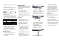
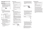
5. Insert the new module into the switch:
Holding the new module with the text on the
front panel upright, carefully slide the
module into the switch slot and press gently
until it snaps into place. Be sure the new
module’s front panel is flush with the switch
panel.
• Store or transport this module only in appropriate
anti-static packaging.
3. Loosen the screws on the installed module
or slot faceplate: Using your fingers or a
flat head screwdriver, turn the screws
securing the module (or faceplate on the
slot) in a counter-clockwise direction until
they are free of the chassis. Be sure not to
completely remove the screws from the
module or faceplate.
6. Secure the new module: Secure the new
module in place by screwing the attached
screws clockwise into the switch’s chassis.
Tighten them enough to secure the module,
but not so tight as to prevent them from
being unscrewed by hand.
7. Connect the network cable: Connect
Ethernet cable to the port on the newly
installed module. See “Connectivity
Guidelines” in this guide for further
information.
4. Remove the installed module or faceplate:
Firmly pull on the screws until the module is
free of the switch. Carefully slide the module
straight out of the slot.
Keep the original faceplate for future use. If
you should remove the module, replace the
faceplate to prevent dust and debris from
TROUBLESHOOTING
If you experience any problems with the module,
check the following items before contacting
Enterasys’s Technical Support:
• Ensure that the device attached to the module is
powered up and operating correctly.
CAUTION: The switch must be powered off before
installing or replacing any module.
2. Remove network cables: If you are
replacing a module, remove the cable
attached to the port on the module.
More details concerning connection options and
network applications can be found in the
VH-2402-L3 Installation Guide. Information on
the module’s configuration options can be
found in the Management Guide that is included
with the base unit.
• Ensure the VH-2402-L3 switch with the Gigabit
Expansion Module is powered up.
Instructions
1. Power off the switch: Disconnect the AC
power cord from the switch. If a redundant
power unit (RPU) is present, disconnect its
DC cable connection to the switch.
switch. The switch’s front-panel LEDs
should indicate the status of the new
connection. Check the LED indicators for
the Gigabit port to ensure that they are
operating correctly. Refer to the table of
LEDs in this guide for a description of the
LED indications. If the module does not
respond, see “Troubleshooting” below.
8. Power on the switch: Reconnect the
previously removed power sources to the
• Ensure that the module is properly seated in the
slot.
• Verify that the attached device is configured to
match the communication mode used by the
module (1 Gbps, and half or full duplex).
• Check the connectors on both ends of the cable
to be sure they are properly engaged.