1
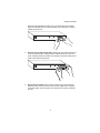
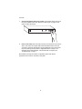
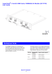
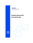
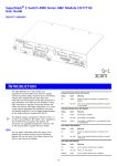
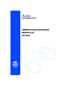
1000BASE-SX Gigabit Uplink Module
EM4501C-SX-SC
User Guide
Contents
Contents
Description of Hardware
Gigabit Module
Gigabit Port LEDs
Installing the Module
Package Contents
Handling the Modules
Instructions
Maximum Cable Length
1
1
1
2
2
2
2
5
Troubleshooting
Product Specifications
5
6
EMI Certification
FCC Class A Certification (USA)
Canada Department of Communications - Class A
BSMI Class A (Taiwan)
VCCI Class A Compliance (Japan)
CE Mark Declaration of Conformance for EMI and Safety (EEC)
7
7
7
7
7
8
Safety Compliance
Warning: Fiber Optic Port Safety
Avertissment: Ports pour fibres optiques - sécurité sur le plan optique
Warnhinweis: Faseroptikanschlüsse - Optische Sicherheit
Underwriters Laboratories Inc. (USA)
Wichtige Sicherheitshinweise (Germany)
9
9
9
9
9
10
Description of Hardware
Gigabit Module
The EM4501C-SX-SC Gigabit module provides a gigabit port which can be used for
a high-speed backbone or server connection. It contains one 1000BASE-SX port
that can be connected to a site up to 550 m (1805 ft.) away with fiber cable. At
present, suitable units include the CheetahSwitch Workgroup-3526C (ES3526C).
Detailed information about configuring these modules and advice about Fast
Ethernet configuration rules can be found in the switch’s user guide.
Warning: Before installing or removing the EM4501C-SX-SC module, first disconnect the
switch from the main power supply. For full safety instructions, please refer to
the user guide that accompanies the switch.
Gigabit Port LEDs
LEDs for the rear panel slots are provided on the front of the switch which indicate
whether or not a network connection is established on the gigabit port. The following
table details the indicator functions provided by the module:
Extender Module LEDs
LEDs
Condition
Status
Link/Activity
On
A valid link has been established on the port.
Flashing
Traffic is crossing the port.
1
User Guide
Installing the Module
Caution: Do not install this module in any unit other than the CheetahSwitch
Workgroup-3526C (ES3526C). Contact your distributor for advice on newly
released switches which may be designed for use with this module.
The EM4501C-SX-SC gigabit module is field installable. Just follow the instructions
below.
Package Contents
This package includes:
• One EM4501C-SX-SC gigabit module
• This User Guide
• Owner registration card
Handling the Modules
Caution: The EM4501C-SX-SC module can easily be damaged by electrostatic
discharge.
To prevent electrostatic damage, observe the following guidelines:
•
•
•
•
Do not remove the module from its packaging until you are ready to install it.
Do not touch any of the module’s pins, connectors or components.
Hold the module only by its edges or front panel.
Wear an anti-static wristband connected to a suitable earth ground whenever
handling the module.
• Store or transport this module only in appropriate anti-static packaging.
Instructions
Caution: The switch must be powered off before installing or replacing any module.
1.
Power off the switch: Disconnect the AC power cord from the switch.
2.
Remove network cables: If you are replacing a module, remove the cable
attached to the port on the module.
3.
Loosen the screws on the installed module or slot faceplate: Using your
fingers or a flathead screwdriver, turn the screws securing the module (or
faceplate on the slot) in a counter-clockwise direction until they are free of the
chassis. Be sure not to completely remove the screws from the module or
faceplate.
4.
Remove the installed module or faceplate: Firmly pull on the screws until the
module is free of the switch. Carefully slide the module straight out of the slot.
2
Description of Hardware
Keep the original faceplate for future use. If you should remove the module,
replace the faceplate to prevent dust and debris from entering the unit and to
maintain proper air flow.
5.
Insert the new module into the switch: Holding the new module with the text
on the front panel upright, carefully slide the module into the slot on the rear
panel, and press gently until it snaps into place. Be sure the new module’s front
panel is flush with the switch panel.
6.
Secure the new module: Secure the new module in place by screwing the
attached screws clockwise into the switch’s chassis. Tighten them enough to
secure the module, but not so tight as to prevent them from being unscrewed
by hand.
3
User Guide
7.
Connect the network cable to the module: Connect fiber cable to the port on
the newly installed module. See “Maximum Cable Length” on page 5 in this
guide for further information.
8.
Power on the switch: Reconnect the previously removed power sources to the
switch. The switch’s front-panel LEDs should indicate the status of the new
connection. Check the LED indicators for the gigabit fiber ports to ensure that
they are operating correctly. Refer to “Gigabit Port LEDs” on page 1 for a
description of the LED indications. If the module does not respond, see
“Troubleshooting” on page 5.
More details concerning the module’s configuration options and network
applications can be found in the switch’s user guide.
4
Troubleshooting
Maximum Cable Length
Cable Types and Specifications
Cable
Type
Max. Length
10BASE-T
Cat. 3, 4, 5 100-ohm UTP
100 m (328 ft.)
RJ-45
100BASE-TX
Cat. 5 100-ohm UTP
100 m (328 ft.)
RJ-45
100BASE-FX
50/125 or 62.5/125 micron core multimode fiber
Half duplex
1000BASE-SX
Connector
412 m (1,351 ft.)
SC or ST
Full duplex
2 km (1.24 miles)
SC or ST
50/125 or 62.5/125 micron core
multimode fiber
See the following
table
SC or ST
Maximum Gigabit Ethernet Cable Length
Fiber Size
Fiber Bandwidth
Maximum Cable Length
62.5/125 micron
160 MHz/km
7-722 ft. (2-220 m)
200 MHz/km
7-902 ft. (2-275 m)
400 MHz/km
7-1641 ft. (2-500 m)
500 MHz/km
7-1805 ft. (2-550 m)
50/125 micron
Troubleshooting
If you experience any problems with the module, check the following items before
contacting Accton Technical Support:
• Ensure the switch with the gigabit module is powered up.
• Ensure that the device attached to the module is powered up and operating
correctly.
• Ensure that the module is properly seated in the slot.
• Verify that the module port is configured to match the communication mode used
by the attached device (full or half duplex).
• Check the connectors on both ends of the cable to be sure they are properly
engaged. When attaching fiber cable to an SC-type port, be sure the plug clicks
into place to ensure that it is properly seated.
• If you are using fiber optic cable with an ST-type connector (in conjunction with the
SC-ST converter*), try switching the TX and RX connectors.
• Be sure the fiber terminators are clean. You can clean the cable plugs by wiping
them gently with a clean tissue or cotton ball moistened with a little ethanol. Dirty
fiber terminators on fiber optic cables will impair the quality of the light transmitted
through the cable.
*
You may use the Cheetah ST Converter (Part Number: ST5002) to attach 62.5/125
micron fiber cable with an ST-type connector to the SC-type port on the module.
5
User Guide
Product Specifications
Access Method
Ports
Network Interface
Communication Mode
Size
Power Consumption
Temperature
Humidity
Standards
Compliances
Emissions
Immunity
Warranty
CSMA/CD
1 1000BASE-SX
SC connector:
62.5/125 or 50/125 micron multimode fiber cable
Full and half duplex, auto-negotiation for flow control
7.2 x 9.1 x 2.4 cm (2.83 x 3.58 x 0.94 in.)
4W maximum
Operating: 0 to 50°C (32 to 122°F)
Storage: -40 to 70°C (-40 to 158°F)
5% to 95%
IEEE 802.3u Fast Ethernet
ISO/IEC 8802-3
CE Mark
FCC Class A
VCCI Class A
Industry Canada Class A
EN55022 (CISPR 22) Class A
C-Tick - AS/NZS 3548 (1995) Class A
IEC 1000-4-2/3/4/6
Three years
6
EMI Certification
EMI Certification
FCC Class A Certification (USA)
Warning: This equipment generates, uses, and can radiate radio frequency energy
and, if not installed and used in accordance with the instruction manual, may cause
interference to radio communications. It has been tested and found to comply with
the limits for a Class A digital device pursuant to Subpart B of Part 15 of FCC Rules,
which are designed to provide reasonable protection against such interference when
operated in a commercial environment. Operation of this equipment in a residential
area is likely to cause interference, in which case the user, at his own expense, will
be required to take whatever measures are required to correct the interference.
You may use 50/125 or 62.5/125 micron multimode fiber optic cable for SC or
ST-type connections.
Canada Department of Communications - Class A
This digital apparatus does not exceed the Class A limits for radio noise emissions
from digital apparatus as set out in the interference-causing equipment standard
entitled “Digital Apparatus,” ICES-003 of the Department of Communications.
Cet appareil numérique respecte les limites de bruits radioélectriques applicables
aux appareils numériques de Classe A prescrites dans la norme sur le matériel
brouilleur: “Appareils Numérques,” NMB-003 édictée par le ministère des
Communications.
BSMI Class A (Taiwan)
VCCI Class A Compliance (Japan)
7
User Guide
CE Mark Declaration of Conformance for EMI and Safety (EEC)
This is to certify that this product complies with ISO/IEC Guide 22 and EN45014.
It conforms to the following specifications:
EMC:
EN55022(1988)/CISPR-22(1985)
EN60555-2(1995)
EN60555-3
IEC1000-4-2(1995)
IEC1000-4-3(1995)
IEC1000-4-4(1995)
IEC1000-4-6(1995)
class A
class A
4kV CD, 8kV AD
3V/m
1kV - (power line),
0.5kV - (signal line)
3Vrms
This product complies with the requirements of the Low Voltage Directive 73/23/EEC
and the EMC Directive 89/336/EEC.
Warning! Do not plug a phone jack connector in the RJ-45 port. This may damage
this device. Les raccordeurs ne sont pas utilisé pour le système
téléphonique!
8
Safety Compliance
Safety Compliance
Warning: Fiber Optic Port Safety
When using a fiber optic media expansion module, never look at
the transmit laser while it is powered on. Also, never look directly
at the fiber TX port and fiber cable ends when they are powered on.
Avertissment: Ports pour fibres optiques sécurité sur le plan optique
Ne regardez jamais le laser tant qu’il est sous tension. Ne
regardez jamais directement le port TX (Transmission) à fibres optiques et les
embouts de câbles à fibres optiques tant qu'ils sont sous tension.
Warnhinweis: Faseroptikanschlüsse Optische Sicherheit
Niemals ein Übertragungslaser betrachten, während dieses
eingeschaltet ist. Niemals direkt auf den Faser-TX-Anschluß und auf die
Faserkabelenden schauen, während diese eingeschaltet sind.
Underwriters Laboratories Inc. (USA)
Important! Before making connections, make sure you have the correct Cord Set.
Check it (read the label on the cable) against the following specification list.
Operating Voltage
120 Volts
240 Volts (Europe only)
Cord Set Specifications
UL Listed/CSA Certified Cord Set
Minimum 18 AWG
Type SVT or SJT three conductor cord
Maximum length of 15 feet
Parallel blade, grounding type attachment plug rated 15A,
125V
Cord Set with H05VV-F cord having three conductors
with minimum diameter of 0.75 mm2
IEC-320 receptacle
Male plug rated 10A, 250V
9
User Guide
Wichtige Sicherheitshinweise (Germany)
1.
2.
3.
4.
5.
6.
7.
8.
9.
10.
11.
12.
13.
14.
15.
Bitte lesen Sie diese Hinweise sorgfältig durch.
Heben Sie diese Anleitung für den späteren Gebrauch auf.
Vor jedem Reinigen ist das Gerät vom Stromnetz zu trennen. Verwenden Sie keine
Flüssigoder Aerosolreiniger. Am besten eignet sich ein angefeuchtetes Tuch zur Reinigung.
Die Netzanschlu ßsteckdose soll nahe dem Gerät angebracht und leicht zugänglich sein.
Das Gerät ist vor Feuchtigkeit zu schützen.
Bei der Aufstellung des Gerätes ist auf sicheren Stand zu achten. Ein Kippen oder Fallen
könnte Beschädigungen hervorrufen.
Die Belüftungsöffnungen dienen der Luftzirkulation, die das Gerät vor Überhitzung
schützt. Sorgen Sie dafür, daß diese Öffnungen nicht abgedeckt werden.
Beachten Sie beim Anschluß an das Stromnetz die Anschlußwerte.
Verlegen Sie die Netzanschlußleitung so, daß niemand darüber fallen kann. Es sollte
auch nichts auf der Leitung abgestellt werden.
Alle Hinweise und Warnungen, die sich am Gerät befinden, sind zu beachten.
Wird das Gerät über einen längeren Zeitraum nicht benutzt, sollten Sie es vom Stromnetz
trennen. Somit wird im Falle einer Überspannung eine Beschädigung vermieden.
Durch die Lüftungsöffnungen dürfen niemals Gegenstände oder Flüssigkeiten in das
Gerät gelangen. Dies könnte einen Brand bzw. elektrischen Schlag auslösen.
Öffnen sie niemals das Gerät. Das Gerät darf aus Gründen der elektrischen Sicherheit
nur von authorisiertem Servicepersonal geöffnet werden.
Wenn folgende Situationen auftreten ist das Gerät vom Stromnetz zu trennen und von
einer qualifizierten Servicestelle zu überprüfen:
a. Netzkabel oder Netzstecker sind beschädigt.
b. Flüssigkeit ist in das Gerät eingedrungen.
c.
Das Gerät war Feuchtigkeit ausgesetzt.
d. Wenn das Gerät nicht der Bedienungsanleitung entsprechend funktioniert oder Sie
mit Hilfe dieser Anleitung keine Verbesserung erzielen.
e. Das Gerät ist gefallen und/oder das Gehäuse ist beschädigt.
f.
Wenn das Gerät deutliche Anzeichen eines Defektes aufweist.
Zum Netzanschluß dieses Gerätes ist eine geprüfte Leitung zu verwenden. Für einen
Nennstrom bis 6A und einem Gerätegewicht größer 3kg ist eine Leitung nicht leichter als
H05VV-F, 3G, 0.75mm2 einzusetzen.
Der arbeitsplatzbezogene Schalldruckpegel nach DIN 45 635 Teil 1000 beträgt 70dB(A) oder
weniger.
10
Warranty
Accton warrants to the original owner that the product delivered in this package will be free from
defects in material and workmanship for a period of three (3) years from the date of purchase from
Accton or itís Authorized reseller. For the warranty to apply, you must register your purchase by
returning the registration card indicating the date of purchase and including proof of purchase. There
will be a minimal charge to replace consumable components, such as fuses, power transformers, and
mechanical cooling devices. The warranty does not cover the product if it is damaged in the process of
being installed. Accton recommends that you have the company from whom you purchased this
product install it.
THE ABOVE WARRANTY IS IN LIEU OF ANY OTHER WARRANTY, WHETHER EXPRESS, IMPLIED
OR STATUTORY, INCLUDING BUT NOT LIMITED TO ANY WARRANTY OF MERCHANTABILITY,
FITNESS FOR A PARTICULAR PURPOSE, OR ANY WARRANTY ARISING OUT OF ANY
PROPOSAL, SPECIFICATION OR SAMPLE. ACCTON SHALL NOT BE LIABLE FOR INCIDENTAL
OR CONSEQUENTIAL DAMAGES. ACCTON NEITHER ASSUMES NOR AUTHORIZES ANY
PERSON TO ASSUME FOR IT ANY OTHER LIABILITY.
Copyright
Copyright © 2000 by Accton Technology Corporation. All rights reserved.
No part of this document may be copied or reproduced in any form or by any means without the prior
written consent of Accton Technology Corporation.
Trademarks
Accton is a trademark of Accton Technology Corporation. Other trademarks or brand names
mentioned herein are trademarks or registered trademarks of their respective companies.
Disclaimer
Accton makes no warranties with respect to this documentation and disclaims any implied warranties
of merchantability, quality, or fitness for any particular purpose. The information in this document is
subject to change without notice. Accton reserves the right to make revisions to this publication without
obligation to notify any person or entity of any such changes.
International Headquarters
No. 1 Creation Road III,
Science-based Industrial Park
Hsinchu 300, Taiwan, R.O.C.
Phone: 886-3-5770-270
FAX: 886-3-5770-267
Internet: [email protected]
USA Headquarters
P.O. Box 51420
Irvine, CA 92619-1420
Phone Numbers Sales:
888-398-2101, 949-707-4800
Support: 888-398-4101, 949-707-4847
RMA:
888-398-3101, 949-707-4828
FAX: 949-707-2460
EM4501C-SX-SC
E062000-R01
150217-102