1
EXABYTE EZ17M AND
EZ17A AUTOLOADER
INSTALLATION
AND
OPERATION
328824-004
Copyright
Copyright 1998–2001 by Exabyte Corporation. All rights reserved. This item and
the information contained herein are the property of Exabyte Corporation. No
part of this document may be reproduced, transmitted, transcribed, stored in a
retrieval system, or translated into any language or computer language in any
form or by any means, electronic, mechanical, magnetic, optical, chemical,
manual, or otherwise, without the express written permission of Exabyte
Corporation, 1685 38th Street, Boulder, Colorado 80301.
Disclaimer
Exabyte Corporation makes no representation or warranties with respect to the
contents of this document and specifically disclaims any implied warranties of
merchantability or fitness for any particular purpose. Further, Exabyte
Corporation reserves the right to revise this publication without obligation of
Exabyte Corporation to notify any person ororganization of such revision or changes.
Trademark Notices
Exabyte and Exapak are US registered trademarks of Exabyte Corporation. M2,
MammothTape, SmartClean, EZ17 and NetStorM are trademarks of Exabyte
Corporation. People Working for You and SupportSuite are service marks of
Exabyte Corporation. Advanced Intelligent Tape (AIT) is a trademark of Sony
Electronics, Inc. All other product names are trademarks or registered
trademarks of their respective owners.
Note:
The most current information about this product is available at
Exabyte’s World Wide Web site (www.exabyte.com).
Exabyte Corporation
1685 38th Street
Boulder, Colorado 80301
328824-004
ii
Exabyte EZ17M and EZ17A
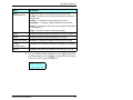
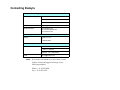
Revision History
Revision
Date
Description
000
August 1998
Beta release.
001
August 1998
Initial release.
002
March 1999
Added information about the LVD SCSI
configuration and Exabyte
Mammoth-LT.
003
January 2000
Added Exabyte Mammoth-2 tape drive
information.
004
June 2001
Removed section on replacing the fuse
and added AIT information.
Safety Agency Standards
The Exabyte EZ17M and EZ17A complies with the following domestic and
international product safety standards:
• UL Standard 1950, 3rd Edition, Information Technology Equipment
including Electrical Business Equipment
• CSA Standard C22.2 No. 950-95, Safety of Information Technology
Equipment including Electrical Business Equipment
• IEC 950/EN60950, Safety of Information Technology Equipment
including Electrical Business Equipment
FCC Notice
This equipment has been tested and found to comply with the limits for a digital
device, pursuant to 47CFR, Part 15, Subpart B, Class B of the FCC Rules. These
limits are designed to provide reasonable protection against harmful
interference when the equipment is operated in a residential, commercial, or
light-industrial environment. This equipment generates, uses, and can radiate
radio frequency energy and, if not installed and used in accordance with this
instruction manual, may cause harmful interference to radio communications.
Shielded cables are required for this device to comply with FCC Rules. Use
shielded cables when connecting this device to others.
Installation and Operation
iii
Industry Canadian Notice per ICES-003
This Class B digital apparatus meets all requirements of the Canadian
Interference-Causing Equipment Regulations.
French Cet appareil numérique de la classe B respecte toutes les exigences du
Règlement sur le matériel brouilleur du Canada.
European Union
This equipment complies with the following standards:
• EN55022/CISPR22 Class B
• EN50082-1:1997 or EN55024:1998
Bureau of Standards, Metrology, and Inspection (BSMI) – Taiw an
This equipment has been tested and complies with BSMI CNS 13438 Class B.
Australia/ New Zealand
This equipment has been tested and complies with AS/NZS 3548.
iv
Exabyte EZ17M and EZ17A
Product Warranty Caution
The Exabyte® EZ17M or EZ17A Autoloader (EZ17) is warranted to be free from
defects in materials, parts, and workmanship and will conform to the current
product specification upon delivery. For the specific details of your warranty,
refer to your sales contract or contact the company from which the autoloader
was purchased.
The warranty for the autoloader shall not apply to failures of any unit when:
• The autoloader is repaired by anyone other than the Exabyte’s
personnel or approved agent.
• The autoloader is physically abused or is used in a manner that is
inconsistent with the operating instructions or product specification
defined by Exabyte.
• The autoloader fails because of accident, misuse, abuse, neglect,
mishandling, misapplication, alteration, faulty installation,
modification, or service by anyone other than the factory service
center or its approved agent.
• The autoloader is repaired by anyone, including an approved agent,
in a manner that is contrary to the maintenance or installation
instructions supplied by Exabyte.
• Exabyte’s serial number tag is removed.
• The autoloader is damaged because of improper packaging on
return.
CAUTION
Returning the autoloader in unauthorized packaging may
damage the unit and void the warranty.
If problems with the autoloader occur, contact your
maintenance organization; do not void the product warranty
by allowing untrained or unauthorized personnel to attempt
repairs.
Installation and Operation
v
Notes
vi
Exabyte EZ17M and EZ17A
Contents
1
Product Overview . . . . . . . . . . . . . . . . . . . . . . . . . . . . . . . . . . . . . . 1
About the Exabyte EZ17 Autoloader . . . . . . . . . . . . . . . . . . . . . . . . . . . . .
Autoloader components . . . . . . . . . . . . . . . . . . . . . . . . . . . . . . . . . . . . . . . .
Front panel components . . . . . . . . . . . . . . . . . . . . . . . . . . . . . . . . . . .
Internal components . . . . . . . . . . . . . . . . . . . . . . . . . . . . . . . . . . . . . .
Back panel components. . . . . . . . . . . . . . . . . . . . . . . . . . . . . . . . . . . .
2
Hardware Installation. . . . . . . . . . . . . . . . . . . . . . . . . . . . . . . . . . . 7
Unpacking the autoloader . . . . . . . . . . . . . . . . . . . . . . . . . . . . . . . . . . . . . .
Obtaining accessories and equipment . . . . . . . . . . . . . . . . . . . . . . . . . . .
Selecting cartridges. . . . . . . . . . . . . . . . . . . . . . . . . . . . . . . . . . . . . . .
Selecting cleaning cartridges . . . . . . . . . . . . . . . . . . . . . . . . . . . . . .
Selecting application software . . . . . . . . . . . . . . . . . . . . . . . . . . . . .
Preparing the autoloader for installation . . . . . . . . . . . . . . . . . . . . . . . .
Preparing and installing cartridges . . . . . . . . . . . . . . . . . . . . . . . . . . . . .
Connecting the autoloader to the SCSI bus . . . . . . . . . . . . . . . . . . . . . .
Connecting the power cord . . . . . . . . . . . . . . . . . . . . . . . . . . . . . . . . . . .
Powering on the autoloader . . . . . . . . . . . . . . . . . . . . . . . . . . . . . . . . . . .
Verifying the hardware installation . . . . . . . . . . . . . . . . . . . . . . . . . . . . .
3
2
3
3
4
5
8
10
11
15
16
17
18
21
24
25
26
Configuration . . . . . . . . . . . . . . . . . . . . . . . . . . . . . . . . . . . . . . . . 27
Using the operator panel . . . . . . . . . . . . . . . . . . . . . . . . . . . . . . . . . . . . . .
Operator keys . . . . . . . . . . . . . . . . . . . . . . . . . . . . . . . . . . . . . . . . . . .
Status screen . . . . . . . . . . . . . . . . . . . . . . . . . . . . . . . . . . . . . . . . . . . .
Error codes. . . . . . . . . . . . . . . . . . . . . . . . . . . . . . . . . . . . . . . . . . . . . .
Menus . . . . . . . . . . . . . . . . . . . . . . . . . . . . . . . . . . . . . . . . . . . . . . . . .
Configuring the autoloader . . . . . . . . . . . . . . . . . . . . . . . . . . . . . . . . . . . .
Setting the SCSI IDs . . . . . . . . . . . . . . . . . . . . . . . . . . . . . . . . . . . . . .
Setting the Emulation mode . . . . . . . . . . . . . . . . . . . . . . . . . . . . . .
Setting the Robot Control mode . . . . . . . . . . . . . . . . . . . . . . . . . . .
Setting the LCD Security option . . . . . . . . . . . . . . . . . . . . . . . . . . .
Checking the setup . . . . . . . . . . . . . . . . . . . . . . . . . . . . . . . . . . . . . . . . . . .
Beginning autoloader operations . . . . . . . . . . . . . . . . . . . . . . . . . . . . . . .
Installation and Operation
28
29
30
30
31
33
34
36
38
40
44
45
vii
4
Autoloader Operation . . . . . . . . . . . . . . . . . . . . . . . . . . . . . . . . . 47
Removing and replacing the magazine . . . . . . . . . . . . . . . . . . . . . . . . . .
Removing the magazine . . . . . . . . . . . . . . . . . . . . . . . . . . . . . . . . . . .
Installing the magazine. . . . . . . . . . . . . . . . . . . . . . . . . . . . . . . . . . . .
Storing cartridges . . . . . . . . . . . . . . . . . . . . . . . . . . . . . . . . . . . . . . . . . . . . .
Operating the autoloader in Sequential mode . . . . . . . . . . . . . . . . . . . .
Sequential options . . . . . . . . . . . . . . . . . . . . . . . . . . . . . . . . . . . . . . . .
Loop option. . . . . . . . . . . . . . . . . . . . . . . . . . . . . . . . . . . . . . . . . . . . . .
Restart option . . . . . . . . . . . . . . . . . . . . . . . . . . . . . . . . . . . . . . . . . . . .
Next Cart option . . . . . . . . . . . . . . . . . . . . . . . . . . . . . . . . . . . . . . . . .
Setting Sequential mode options . . . . . . . . . . . . . . . . . . . . . . . . . . . . . . . .
Avoiding interruptions . . . . . . . . . . . . . . . . . . . . . . . . . . . . . . . . . . . . . . . .
Viewing autoloader information . . . . . . . . . . . . . . . . . . . . . . . . . . . . . . . .
Viewing code versions . . . . . . . . . . . . . . . . . . . . . . . . . . . . . . . . . . . .
Viewing statistics . . . . . . . . . . . . . . . . . . . . . . . . . . . . . . . . . . . . . . . . .
Viewing system sensors . . . . . . . . . . . . . . . . . . . . . . . . . . . . . . . . . . .
Viewing inventory information. . . . . . . . . . . . . . . . . . . . . . . . . . . . .
Performing hardware exercises . . . . . . . . . . . . . . . . . . . . . . . . . . . . . . . . .
Using elements . . . . . . . . . . . . . . . . . . . . . . . . . . . . . . . . . . . . . . . . . . .
Using the Demo Menu . . . . . . . . . . . . . . . . . . . . . . . . . . . . . . . . . . . .
Using the Command Menu . . . . . . . . . . . . . . . . . . . . . . . . . . . . . . . .
Resetting the autoloader . . . . . . . . . . . . . . . . . . . . . . . . . . . . . . . . . . . . . . .
5
Tape Drive Operation . . . . . . . . . . . . . . . . . . . . . . . . . . . . . . . . . 75
Cleaning the drive . . . . . . . . . . . . . . . . . . . . . . . . . . . . . . . . . . . . . . . . . . . .
Resetting the drive . . . . . . . . . . . . . . . . . . . . . . . . . . . . . . . . . . . . . . . . . . . .
Displaying information about the drive . . . . . . . . . . . . . . . . . . . . . . . . .
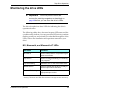
Monitoring the drive LEDs . . . . . . . . . . . . . . . . . . . . . . . . . . . . . . . . . . . . .
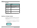
Ejecting a cartridge manually . . . . . . . . . . . . . . . . . . . . . . . . . . . . . . . . . . .
viii
48
48
50
52
53
54
54
54
56
56
59
60
60
61
63
65
67
67
69
70
72
76
79
79
85
86
Exabyte EZ17M and EZ17A
6
Diagnostics and Firmw are . . . . . . . . . . . . . . . . . . . . . . . . . . . . . . 89
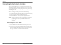
Connecting to the Console interface . . . . . . . . . . . . . . . . . . . . . . . . . . . .
Connecting the serial cable . . . . . . . . . . . . . . . . . . . . . . . . . . . . . . . .
Setting the autoloader’s baud rate. . . . . . . . . . . . . . . . . . . . . . . . . .
Accessing Console using HyperTerminal . . . . . . . . . . . . . . . . . . . .
Setting the autoloader to Console mode . . . . . . . . . . . . . . . . . . . .
Upgrading firmware via Console . . . . . . . . . . . . . . . . . . . . . . . . . . . . . . .
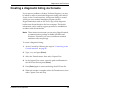
Creating a diagnostic listing via Console. . . . . . . . . . . . . . . . . . . . . . . . .
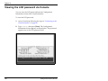
Viewing the LCD password via Console . . . . . . . . . . . . . . . . . . . . . . . .
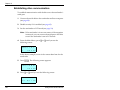
Communicating with the tape drive . . . . . . . . . . . . . . . . . . . . . . . . . . .
Setting up the hardware and software . . . . . . . . . . . . . . . . . . . . .
Establishing drive communication . . . . . . . . . . . . . . . . . . . . . . . .
Using the M2 or Mammoth Monitor software . . . . . . . . . . . . . .
7
90
90
91
92
94
96
99
100
101
101
102
104
Troubleshooting . . . . . . . . . . . . . . . . . . . . . . . . . . . . . . . . . . . . . 105
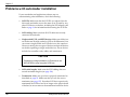
Problems with autoloader installation . . . . . . . . . . . . . . . . . . . . . . . . . . 106
Problems with drive operation . . . . . . . . . . . . . . . . . . . . . . . . . . . . . . . . 108
Problems with autoloader operation . . . . . . . . . . . . . . . . . . . . . . . . . . . 109
8
Service . . . . . . . . . . . . . . . . . . . . . . . . . . . . . . . . . . . . . . . . . . . . . 111
Cleaning requirements . . . . . . . . . . . . . . . . . . . . . . . . . . . . . . . . . . . . . . .
Using touch-up paint on the housing . . . . . . . . . . . . . . . . . . . . . . . . . .
Returning the autoloader for service . . . . . . . . . . . . . . . . . . . . . . . . . . .
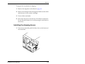
Preparing the autoloader for shipping . . . . . . . . . . . . . . . . . . . . .
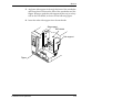
Installing the shipping braces. . . . . . . . . . . . . . . . . . . . . . . . . . . . .
Packing the autoloader . . . . . . . . . . . . . . . . . . . . . . . . . . . . . . . . . .
Installation and Operation
111
112
112
112
113
117
ix
A
Specifications. . . . . . . . . . . . . . . . . . . . . . . . . . . . . . . . . . . . . . . 119
Overall specifications for the autoloader . . . . . . . . . . . . . . . . . . . . . . . .
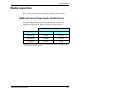
Media capacities . . . . . . . . . . . . . . . . . . . . . . . . . . . . . . . . . . . . . . . . . . . . .
AME with SmartClean media for M2 drives . . . . . . . . . . . . . . . . .
AME media for Mammoth or Mammoth-LT drives. . . . . . . . . . .
AME media for AIT-2 drives. . . . . . . . . . . . . . . . . . . . . . . . . . . . . . .
Media compatibility . . . . . . . . . . . . . . . . . . . . . . . . . . . . . . . . . . . . . . . . . .
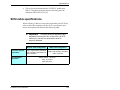
Power cord requirements . . . . . . . . . . . . . . . . . . . . . . . . . . . . . . . . . . . . .
SCSI cable specifications . . . . . . . . . . . . . . . . . . . . . . . . . . . . . . . . . . . . . .
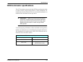
SCSI terminator specifications . . . . . . . . . . . . . . . . . . . . . . . . . . . . . . . . .
SCSI adapter specifications . . . . . . . . . . . . . . . . . . . . . . . . . . . . . . . . . . . .
B
SCSI Configuration . . . . . . . . . . . . . . . . . . . . . . . . . . . . . . . . . . 129
SCSI components . . . . . . . . . . . . . . . . . . . . . . . . . . . . . . . . . . . . . . . . . . . .
Considerations for installing the autoloader on the SCSI bus . . . . . .
LVD SCSI . . . . . . . . . . . . . . . . . . . . . . . . . . . . . . . . . . . . . . . . . . . . . . .
Wide SCSI . . . . . . . . . . . . . . . . . . . . . . . . . . . . . . . . . . . . . . . . . . . . . .
SCSI IDs . . . . . . . . . . . . . . . . . . . . . . . . . . . . . . . . . . . . . . . . . . . . . . . .
SCSI terminator . . . . . . . . . . . . . . . . . . . . . . . . . . . . . . . . . . . . . . . . .
C
119
121
121
122
122
123
124
125
127
128
129
130
130
130
131
131
Error Codes . . . . . . . . . . . . . . . . . . . . . . . . . . . . . . . . . . . . . . . . 133
Index . . . . . . . . . . . . . . . . . . . . . . . . . . . . . . . . . . . . . . . . . . . . . . . . . 145
Contacting Exabyte . . . . . . . . . . . . . . . . . . . . . . . . .
x
Inside back cover
Exabyte EZ17M and EZ17A
How to use this manual
This manual describes how to install, configure, operate,
maintain, and troubleshoot the Exabyte EZ17M and EZ17A
autoloader.
Note: This manual uses “EZ17”to refer to either the EZ17M
or EZ17A.
First-time installation
If you are installing the autoloader for the first time, refer to
the following chapters:
§ Chapter 1 provides an overview of the autoloader’s
features and components. Appendix A lists additional
autoloader and drive specifications.
§ Chapter 2 provides instructions for installing the
autoloader hardware, connecting the autoloader to the
SCSI bus, and powering on the autoloader. Appendix B
provides additional information about SCSI
configurations.
§ Chapter 3 describes how to configure the autoloader for
operation on the SCSI bus and for operation with your
application software. Follow the steps at the end of this
chapter to verify the setup and to begin autoloader
operation.
Installation and Operation
xi
Operation
During normal autoloader operations, you do not need to
intervene in cartridge processing. However, you may need
to refer to these chapters for some occasional tasks.
§ Chapter 4 describes how to replace the magazine, how
to store cartridges, how to operate the autoloader in
Sequential mode, and how to view autoloader
information. It also describes how to perform hardware
exercises and how to reset the autoloader.
§ Chapter 5 describes how clean and reset the drive, and
how to display information about the drive. It also
provides information about how to monitor the drive
LEDs and how to manually eject a cartridge.
Troubleshooting and service
Refer to these chapters for troubleshooting and service:
§ Chapter 6 describes how to use the Console firmware to
perform a diagnostic listing, update the firmware, and
view the LCD password.
§ Chapter 7 describes basic troubleshooting
recommendations.
§ Chapter 8 describes basic maintenance and how to
return the autoloader for service, if necessary.
§ Appendix C lists the error codes displayed on the
autoloader’s LCD and provides information about
resolving various error conditions.
xii
Exabyte EZ17M and EZ17A
Note: For the most current information about this product,
visit Exabyte’s web site (www.exabyte.com).
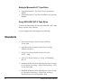
Related publications
Exabyte EZ17 Autoloader
§ Exabyte EZ17 Autoloader SCSI Reference, 328823
§ Exabyte EZ17 MammothTape Technology Autoloader Product
Specification, 328822
§ Exabyte EZ17A AIT-2 Autoloader Product Specification,
1008278
Exabyte M ammoth-2 Tape Drive
§ Exabyte Mammoth-2 Tape Drive SCSI Reference, 330876
§ Exabyte Mammoth-2 Tape Drive Product Specification,
330874
§ Exabyte Mammoth-2 Tape Drive Installation and Operation,
330875
Exabyte M ammoth Tape Drive
§ Exabyte Mammoth Tape Drive Product Specification, 306482
§ Exabyte Mammoth Tape Drive SCSI Reference, 306483
§ Exabyte Mammoth Tape Drive Installation and Operation,
306484
Installation and Operation
xiii
Exabyte M ammoth-LT Tape Drive
§ Exabyte Mammoth-LT Tape Drive Product Specification,
340230
§ Exabyte Mammoth-LT Tape Drive Installation and Operation,
326984
Sony SDX-500C AIT-2 Tape Drive
To locate documentation for the Sony SDX-500C AIT-2 tape
drive, visit the Sony web site:
www.storagebysony.com/support/consumer.asp
Standards
§ ANSI Small Computer System Interface (SCSI-2),
X3.131-1994
§ ANSI Helical-Scan Digital Computer Tape Cartridge,
X3B5/89-136, Rev. 6
§ ANSI SCSI-3 Fast20 Parallel Interface (Fast-20),
X3.277 – 1996
§ ANSI SCSI Parallel Interface-2 (SPI-2), X3T10/1142D,
Rev. 11
§ Standard ECMA-249, 8mm Wide Magnetic Tape Cartridge
for Information Interchange – Helical Scan Recording – DA-2
Format, June 1998
§ Standard ECMA-293, 8mm Wide Magnetic Tape Cartridge
for Information Interchange – Helical Scan Recording –
MammothTape-2 Format, December, 1999
xiv
Exabyte EZ17M and EZ17A
§ TapeAlert Specification, Version 2.0, November, 1997
§ IEEE 802.3 Carrier Sense Multiple Access with Collision
Detection (CSMA/CD) Access Method and Physical Layer
Specifications, 1985
§ EIA Rack Standards, RS-310-B
Conventions used in this manual
This manual uses the following conventions:
[Enter]
Boxed text indicates keys on the operator panel.
Note: Notes provide additional information.
➤ Important
Information next to the word
“ Important” helps you complete a procedure or
avoid extra steps.
CAUTION
Boxed text under the word “ CAUTION” provides
information you must know to avoid damaging
the autoloader or tape drive or losing data.
Installation and Operation
xv
WARNING!
Boxed text under the heading “ WARNING!”
provides information you must know to avoid
personal injury.
xvi
Exabyte EZ17M and EZ17A
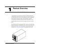
1
Product Overview
Congratulations on selecting the Exabyte® EZ17M autoloader
with a MammothTape drive or an Exabyte EZ17Aautoloader with
an AIT-2 tape drive. Your new autoloader provides unattended
data storage, archiving, backup, and retrieval for small PC
workgroups to multi-server networks. The autoloader’s robot
automatically loads and removes cartridges from the enclosed
drive.
The EZ17M or EZ17A autoloader (EZ17), shown in the following
figure, is designed as a standalone unit. If you want to mount the
autoloader in a rack, you can purchase a rack-mount kit from
Exabyte (see “Contacting Exabyte”on the inside back cover).
Installation and Operation
1
Chapter 1
About the Exabyte EZ17 Autoloader
The autoloader includes one data cartridge magazine and one of
the following factory-installed tape drives:
§
§
§
§
Exabyte Mammoth-2 (M2TM)
Exabyte Mammoth
Exabyte Mammoth-LT
Sony SDX-500C AIT-2
The autoloader is available in the following wide SCSI
configurations:
§ Single-ended (SE)
§ Low-voltage differential (LVD)
§ High-voltage differential (HVD)
Note: The M2 and AIT-2 drives are only available with LVD.
The autoloader typically operates as two SCSI devices (the drive
and the autoloader) on one wide SCSI bus. Mammoth and
Mammoth-LT are SCSI-2 devices. Mammoth-2 and AIT-2 are
Ultra2 LVD SCSI devices. If you want to install the autoloader on
a narrow SCSI bus, you need to use an adapter.
2
Exabyte EZ17M and EZ17A
Product Overview
Autoloader components
This section provides an introduction to the physical components
of your autoloader.
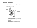
Front panel components
LCD
Keypad
EN
TE
R
ES
ME
NU
RE
SE
T
CA
PE
STA
TU
S
RE
MO
MA VE
G.
Data cartridge
magazine
§ LCD and keypad (operator panel). The two-line LCD (liquid
crystal display) and keypad allow you to view the operational
status of the autoloader, access a menu of operations, and view
status messages.
§ Data cartridge magazine. The autoloader includes one
removable magazine that stores up to seven cartridges.
Installation and Operation
3
Chapter 1
Internal components
Tape drive
Robot
Magazine present
sensor
§ Robot. The robot moves a cartridge between the magazine
and the drive.
§ Magazine present sensor. The magazine present sensor
detects whether a magazine is installed.
§ Tape drive. The autoloader contains one drive.
4
Exabyte EZ17M and EZ17A
Product Overview
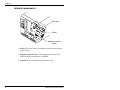
Back panel components
Fan
Power
entry
module
SCSI connectors
9-pin serial port
§ Fan. The fan reduces the autoloader’s operating temperature.
§ Power entry module. The power entry module includes the
AC power connector and the power switch.
§ 9-pin serial port. The serial port allows you to connect a serial
cable to the autoloader and use a terminal emulation program
to perform diagnostics.
§ SCSI connectors. The two wide SCSI connectors allow you to
connect the autoloader to a wide SCSI bus. If desired, you can
connect the autoloader to a narrow SCSI bus using the
appropriate SCSI cable adapter.
Installation and Operation
5
Chapter 1
Notes
6
Exabyte EZ17M and EZ17A
2
Hardware Installation
This chapter describes how to install and set up your autoloader,
which includes the following steps:
§
§
§
§
§
§
§
§
Unpacking the autoloader
Obtaining accessories and equipment
Preparing the autoloader for installation
Preparing and installing cartridges
Connecting the autoloader to the SCSI bus
Connecting the power cord
Powering on the autoloader
Verifying the hardware installation
Installation and Operation
7
Chapter 2
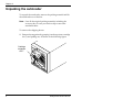
Unpacking the autoloader
To unpack the autoloader, remove the packing material and lift
the autoloader out of the box.
Note: Save all the original packing materials, including the
accessory box, in case you need to ship or move the
autoloader later.
To remove the shipping braces:
1. Remove the magazine by grasping it at the top (near cartridge
slot 7) and pulling out, as shown in the following figure.
Cartridge
magazine
slot 7
8
Exabyte EZ17M and EZ17A
Hardware Installation
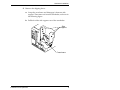
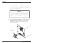
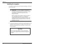
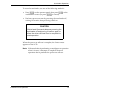
2. Remove the shipping brace:
a. Grasp the cross-brace and disengage it from one side
support. Then remove it from the autoloader, as shown in
the following figure.
b. Pull both of the side supports out of the autoloader.
Side
supports
Cross-brace
Installation and Operation
9
Chapter 2
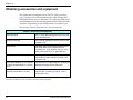
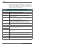
Obtaining accessories and equipment
The autoloader is equipped with a 120 VAC power cord (see
page 124 for power cord requirements for other voltages and
international use) and one magazine. The following table shows
the additional accessories and equipment needed for autoloader
operation. Depending on the configuration you ordered, you
may receive some of these items in your accessory box.
Required accessories and equipment a
Data cartridges
One or more data cartridges may be included
in the accessory box.
Cleaning cartridge
One cleaning cartridge may be included in the
accessory box.b
SCSI cables
One wide, multi-mode (single-ended/LVD) or
HVD SCSI cable may be included in the
accessory box. If you want to use your own
cables, see Appendix A for specifications.
SCSI terminators
One wide, multi-mode (single-ended/LVD) or
HVD SCSI terminator may be included in the
accessory box.
SCSI cable adapters (if you want to
connect the autoloader to a narrow
host)
See Appendix A for specifications. All Exabyte
adapters terminate unused data lines.
Rack-mount hardware (if you want to
install the autoloader in a rack)
A rack-mount hardware kit is available from
Exabyte (see “ Contacting Exabyte” on the
inside back cover).
a
Contact Exabyte to purchase these items (see “ Contacting Exabyte” on the inside of the back cover).
b
The EZ17 with Mammoth-2 or AIT-2 does not include a cleaning cartridge.
10
Exabyte EZ17M and EZ17A
Hardware Installation
Selecting cartridges
The autoloader is available with four different drives. Each drive
has its own media requirements.
CAUTION
Never use video-grade tape for data storage.
Video-grade tape can be less accurate than
data-grade tape and is more abrasive to tape drive
recording heads.
Refer to the appropriate section below for either Exabyte
Mammoth, Mammoth-LT, and M2 drives or Sony SDX-500C
AIT-2 drives.
➤ Important
Because of media management
and application software issues, Exabyte
recommends that you do not mix AME with
SmartClean, AME, AIT-2, or MP data cartridges in
the same autoloader. If you must mix cartridge
types, contact your application software vendor
for assistance.
Installation and Operation
11
Chapter 2
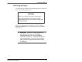
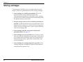
Exabyte M ammoth and M ammoth-LT tape drives
Mammoth and Mammoth-LT read and write data to standard
Exabyte AME data cartridges, shown in the following figure.
These drives cannot read or write to AME with SmartClean
cartridges or AIT cartridges. Standard AME cartridges are
available from Exabyte in lengths of 22 meters, 45 meters,
125 meters, and 170 meters.
Note: Mammoth-LT does not support the AME 170m cartridge.
If you try to insert an Exabyte AME 170m cartridge in
Mammoth-LT, the tape drive automatically ejects it.
12
Exabyte EZ17M and EZ17A
Hardware Installation
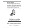
Exabyte M 2 tape drives
TM
wi
t
h
w
it
h
M
a
m
TM
m
o
th
Ta
p
e
M am m othTape
TM
Exabyte M2 drives read and write to AME cartridges with
SmartClean™technology, combining reliable AME recording
media with a short segment of head cleaning material. When the
M2 drive determines cleaning is needed, it locates the cleaning
material and performs the cleaning automatically. AME cartridges
with SmartClean are easily identified by their cobalt-blue color
and are available from Exabyte in lengths of 75 meters,
150 meters, and 225 meters (see page 121 for storage capacities).
5m
22
➤ Important
For optimal performance and
reliability, Exabyte recommends only AME media
with SmartClean for M2 tape drives. M2 can use
other AME media, but will require regular cleaning
with an Exabyte Mammoth cleaning cartridge.
The M2 drive cannot write data to or read data from metal particle
(MP) tape. If you insert an MP cartridge, the drive immediately
ejects it .
Note: M2 does not support AIT cartridges. If you try to insert an
AIT cartridge, the drive automatically ejects it.
Installation and Operation
13
Chapter 2
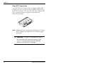
Sony AIT-2 tape drives
Sony SDX-500C AIT-2 drives write to the highly reliable AME
cartridges for AIT-1 and AIT-2 drives, available in lengths of 230
meters and 170 meters. The Sony SDX-500C drive automatically
ejects cartridges it does not support, such as AME with
SmartClean cartridges.
0
0
0
0
3
4
Note: Although the AIT cartridges include Memory in Cassette
(MIC) capability, the library does not currently support
this feature.
➤ Important
Using AIT-1 cartridges in an AIT-2
drive will affect the overall performance of the
drive. To ensure maximum transfer rates and
capacity, use 230m AIT-2 cartridges.
14
Exabyte EZ17M and EZ17A
Hardware Installation
Selecting cleaning cartridges
To select cleaning cartridges for your library, refer to the
appropriate section below for either Exabyte Mammoth,
Mammoth-LT, and M2 drives or Sony SDX-500C AIT-2 drives.
CAUTION
Using cloth swabs, cotton sw abs, cleaning
agents, or cleaning cartridges not approved for
your drive may void the tape drive warranty.
Exabyte M ammoth and M ammoth-LT tape drives
Use an Exabyte Mammoth Cleaning Cartridge or a cleaning
cartridge approved by Exabyte.
Exabyte M 2 tape drives
If you do not use AME media with SmartClean exclusively, the
M2 drive will require regular cleaning with a separate cleaning
cartridge. Use an Exabyte Mammoth Cleaning Cartridge or a
cleaning cartridge approved by Exabyte.
Sony AIT-2 tape drives
The Sony SDX-500C AIT-2 tape drives do not require periodic
cleaning with a separate cleaning cartridge. However, under
extreme environmental conditions, you may need to use an AIT
cleaning cartridge, available from Exabyte.
Installation and Operation
15
Chapter 2
Selecting application software
Make certain the application software you plan to use is
compatible with the autoloader. You can obtain software
compatibility information about Exabyte products from Exabyte’s
web site (www.exabyte.com).
Note: If your application only supports an Exabyte or Sony tape
drive and not the EZ17 autoloader, you can run the
autoloader in Sequential mode (see page 38 and page 53).
If your application does not support the Exabyte EZ17, but
does support the Exabyte 210 library, you can run the
autoloader in 210 Emulation mode (see page 36).
You can install the application software on the host computer
before or after autoloader installation. However, if you install the
software first, you may need to reconfigure it for use with the
autoloader.
16
Exabyte EZ17M and EZ17A
Hardware Installation
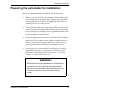
Preparing the autoloader for installation
Before you begin hardware installation, do the following:
§ Make certain the SCSI host bus adapter card installed in the
host computer and the application software are compatible
with the autoloader. Software compatibility information is
available from www.exabyte.com.
§ Ensure that the work area is free from conditions that could
cause electrostatic discharge (ESD). Discharge static electricity
from your body by touching a known grounded surface, such
as your computer’s metal chassis.
§ Locate an appropriate area for the autoloader. The autoloader
must have a level surface near a readily accessible outlet. In
addition, there must be approximately 15 cm (6 inches) of
open area behind the autoloader for adequate air flow.
§ As an option, you can install the autoloader into a rack by
contacting Exabyte for a rack-mount kit, which includes
hardware and installation instructions. See “Contacting
Exabyte” on the inside back cover.
WARNING!
Before performing any installation or maintenance
procedures, be sure that the autoloader power
switch is in the off position and that the pow er cord
is disconnected from the autoloader and the
outlet.
Installation and Operation
17
Chapter 2
Preparing and installing cartridges
This section describes how to prepare cartridges for use in the
autoloader and install cartridges in the magazine. For detailed
information about selecting the appropriate cartridges to use with
your autoloader, see “Selecting cartridges” on page 11.
To prepare and install cartridges:
1. Verify that the write-protect switches on the cartridges are set
correctly, as shown in the following figure. You can use a
ball-point pen or similar instrument to set the write-protect
switch.
0
0
0
0
3
4
W
r
pr ite
ote
ct
W
r
en ite
ab
le
Write-protect switch on
the M2 cartridge
Write-protect switch on
the AIT-2 cartridge
2. Remove the magazine as described on page 8, if necessary.
18
Exabyte EZ17M and EZ17A
Hardware Installation
3. Place the magazine on its back with the cartridge slots facing
up and orient the cartridge as shown in the following figure.
TM
m ge with
22m5Cartrid
lean
artC
Sm
8m
4. Insert a cartridge into each slot.
CAUTION
Avoid touching or opening the cartridge dust
cover when handling the cartridge.
Make sure the cartridge is inserted as show n in
the figure above, or you may damage the
magazine when you place it into the autoloader.
Installation and Operation
19
Chapter 2
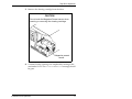
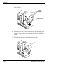
5. Position the magazine so the bottom mounting guide on the
magazine (near cartridge slot 1) aligns with the slot in the
bottom of the opening in the autoloader.
6. Push the top of the magazine in toward the autoloader until
it snaps into place, as shown in the figure below.
CAUTION
Do not force the magazine into the autoloader.
Forcing the magazine may break the cartridge
slot fingers.
20
Exabyte EZ17M and EZ17A
Hardware Installation
Connecting the autoloader to the SCSI bus
This section provides general guidelines for connecting the
autoloader to the SCSI bus. The autoloader and drive operate as
two SCSI devices on one wide SCSI bus. The autoloader can be
connected to a narrow SCSI bus using the appropriate SCSI cable
adapter (see Appendix A).
➤ Important
The drive is a wide SCSI device.
Attaching it to a narrow SCSI bus w ill significantly
reduce its performance.
Before you begin connecting the autoloader to the SCSI bus:
§ Read Appendix B, which provides an overview of the SCSI
interface and some general guidelines for connecting the
autoloader to the SCSI bus.
§ Make sure the host computer and any peripheral devices are
powered off.
CAUTION
To avoid damaging the drive, make sure the
autoloader is powered off when you connect it
to the SCSI bus.
§ Be aware that you can connect single-ended and LVD SCSI
devices to the same SCSI bus. Mixing the two types of devices
results in all devices on the bus operating as single-ended
devices. The EZ17 with M2 or AIT-2 is LVD only.
Installation and Operation
21
Chapter 2
To connect the autoloader to the SCSI bus:
1. Connect a SCSI cable to one of the SCSI connectors on the
back of the autoloader. Use an appropriate SCSI adapter if
you are connecting the autoloader to a narrow SCSI bus (see
page 128 for more information).
CAUTION
All wide SCSI configurations (SE, LVD, and HVD)
use the same 68-pin connector. Connecting a
single-ended or LVD tape drive directly to an HVD
SCSI bus may cause the SCSI bus to hang.
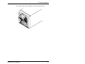
2. If the autoloader is the last device on the SCSI bus, install a
terminator on the unused connector, as shown in the
following figure. See page 127 for information about
terminator requirements.
From host
Terminator
22
Exabyte EZ17M and EZ17A
Hardware Installation
3. If the autoloader is not the last device on the bus, connect a
SCSI cable from the unused SCSI connector to the next device
on the bus, as shown in the following figure.
From host
To next device
Installation and Operation
23
Chapter 2
Connecting the power cord
➤ Important
The pow er cord shipped with the
autoloader is a 120 VAC three-conductor power
cord for use in the United States and Canada. If you
are planning to use an input voltage other than
120 volts AC or if you plan to use the autoloader
outside of the United States or Canada, you must
supply your own power cord. Refer to page 124 for
more information.
1. Verify that the power switch on the back of the autoloader is
off (the 0 is pressed).
2. Connect the female end of the power cord to the power
connector on the back of the autoloader.
Power switch
Power cord
24
Exabyte EZ17M and EZ17A
Hardware Installation
3. Plug the male end of the power cord into the power source.
Note: The autoloader has autoranging voltage selection, so
you do not need to change the voltage setting.
Powering on the autoloader
1. Power on the host computer system.
Note: If your host system requires that attached peripheral
devices be powered on before the host, power on the
autoloader before you power on the host.
2. Push the power switch on the back of the autoloader to the on
position (the I is pressed).
3. Wait while the autoloader performs its power-on sequence.
During this time, the following activities occur:
§ The cooling fan begins to rotate.
§ The LCD illuminates and displays the initialization
sequence.
§ The drive and the autoloader perform their power-on
self-tests.
§ The LCD displays the Status screen.
Installation and Operation
25
Chapter 2
Verifying the hardware installation
If the autoloader does not power on as described, check the
following:
§
§
§
§
§
Is the power switch on?
Is the power cord inserted correctly?
Is the SCSI bus terminated?
Is the host computer system powered on?
Is the SCSI cable connected to the autoloader and host
computer?
§ Is there an error code displayed on the autoloader LCD?
(See Appendix C.)
If you cannot resolve the problem yourself, contact Exabyte (see
“Contacting Exabyte” on the inside back cover).
26
Exabyte EZ17M and EZ17A
3
Configuration
This chapter provides steps for configuring the autoloader, as
follows:
§ Start by reading the first section, “Using the operator panel”
for general information about the keypad, LCD, and menus.
§ Then follow the instructions in “Configuring the autoloader”
on page 33 to set the SCSI IDs and other configuration
options.
§ Be sure to follow the guidelines at the end of this chapter in
“Checking the setup” on page 44.
§ Finally, read “Beginning autoloader operations” on page 45.
Installation and Operation
27
Chapter 3
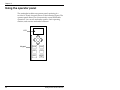
Using the operator panel
The autoloader includes an operator panel consisting of a
two-line LCD and a keypad (shown in the following figure). The
operator panel allows you to interactively control autoloader
operations. You can set autoloader options, check operating
statistics, and exercise autoloader hardware.
LCD
Keypad
28
ENTER
ESCAPE
MENU
STATUS
RESET
REMOVE
MAG.
Exabyte EZ17M and EZ17A
Configuration
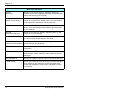
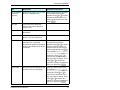
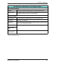
Operator keys
Use the keys on the operator panel to perform the operations
described in the following table.
Keys
Operations
34
Scrolls up or down through the menus or increases
or decreases option values.
12
Shifts the screen arrow left or right one digit when
changing SCSI IDs, password, number of moves,
and so on.
Requests motion to stop and releases the solenoid
so you can remove the magazine.
[REMOVE{{ MAG]
Note: The robot parks in front of the drive. If you
want to access the drive, use the Park & Unlock
command from the Main Menu.
[ESCAPE]
Goes up one level from the current menu option,
cancels changes, and stops tests and
demonstrations that were started through the
Command Menu or Demo Menu.
[ENTER]
Selects the menu (goes down one level) or confirms
a parameter change or selection.
[RESET]
Resets the autoloader (requires confirmation).
Note: To reset the drive, power cycle the
autoloader.
[MENU]
Goes directly to the top of the Main Menu (to the
Security Menu).
[STATUS]
Installation and Operation
Goes directly to the Status screen. The Status
screen is the default after a reset.
29
Chapter 3
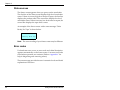
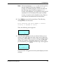
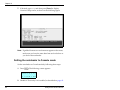
Status screen
The Status screen appears when you power on the autoloader.
The first line of the Status screen displays high-level autoloader
status. If there is not any high-level status to report, the first line
displays the product name. The second line displays low-level
autoloader status. If there is not any low-level status to report, the
second line displays the tape drive’s status.
An example of the Status screen with a status message “Drive
Ready, No Tape” is shown below.
E Z 1 7
D R d y N o T p
Note: The exact wording of your Status screen may be different.
Error codes
If a hardware error occurs, an error code and a brief description
appears automatically on the Status screen. You must correct the
error before operation can continue. (Refer to Appendix C for
help in diagnosing and correcting errors.)
The error message provides the error’s numerical code and a brief
explanation of the error.
30
Exabyte EZ17M and EZ17A
Configuration
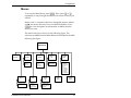
Menus
To access the Main Menu, press [MENU]. Then, press [3] or [4]
repeatedly to loop through the menus and return to where you
started.
Menus with 4 are menus that have changeable options. Menus
with < are menus that only have viewable information. Press
[ENTER] to view the options or information available from the
menu you want.
The menu structure is shown in the following figure. The
selections available from the Main Menu are described in the table
following the figure.
Main Menu
Security
Seq Opt
– Loop
– Restart
– Next Cart
– SCSI
– LCD
– Sequent
– Console
Autoldr
Info
– SCSI IDs
– Drive
– Autoldr
– 210 Emulation
– Code Versions
– System Stats
– System Sensors
– Inventory
Installation and Operation
Command
Menu
– Drive Status
– Drive Display
SCSI
Serial
– Connect to drive
– BaudRat
Drive
Info
Robot
–
–
–
–
–
–
–
–
–
–
Demo
Menu
Move Cart
Init Element
Pos to Element
Self Test
Park
Home Robot
Cycle Pick/Put
Cycle Theta
Cycle Reach
Cycle Solenoid
Park &
Unlock
31
Chapter 3
Main menu selections
Securty
(Security)
Allows you to set LCD security. Shows if security is
disabled. If security is enabled, shows the method that was
used to set security (LCD or SCSI).
Robot
(Robot Control Mode)
Allows you to specify how robot motion is controlled and
shows the current robot control mode. The robot control
modes are SCSI, Sequential, LCD, and Console.
SCSI
Allows you to set SCSI IDs for the autoloader and drive,
allows you to set Exabyte 210 emulation, and shows the
current settings.
Seq Opt
(Sequential Options)
Allows you to set Loop, Restart, and Next Cart to 1, and
shows the current settings.
Serial
Allows you to set the baud rate of the autoloader’s serial
port and connect the serial port to the drive.
Autoldr Info
Allows you to view the code versions, system statistics,
(Autoloader Information) system sensors, and inventory.
Drive Info
Shows drive status, drive error messages, and tape motion
information.
Demo Menu
Provides options for running the autoloader in a continuous
demonstration mode, where the robot randomly moves
cartridges.
Command Menu
Allows you to perform specific robot movements and tests.
Park & Unlock
Allows you to park the robot at the top of its theta axis (the
arced path the robot travels to access cartridges) and
release the magazine’s solenoid (the magazine’s locking
mechanism).
32
Exabyte EZ17M and EZ17A
Configuration
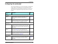
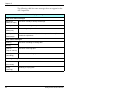
Configuring the autoloader
This section describes how to set the autoloader’s configuration
options. Refer to the table below for an explanation of each
configuration item and determine which ones you need to set.
Then, follow the appropriate steps in this section to set those
options.
Configuration
option
Description
See...
SCSI IDs
Setting SCSI IDs is required for autoloader operation.
View the default settings and change them if
necessary.
Page 34
Emulation Mode
Setting an emulation mode is required if your
application software does not support an Exabyte
EZ17, but does support an Exabyte 210 library.
Page 36
Robot Control
Setting the robot control option determines which
interface is used to control the motion of the robot.
The control mode options are SCSI, Sequential, LCD,
and Console.
Page 38
Sequential
Options
Provides options for using the autoloader’s Sequential Page 38
mode. (See page 53 for more information and
instructions for setting the Sequential mode options.)
Serial
Allows you to set the baud rate for the autoloader’s
serial port or choose to communicate with the drive
over the serial port (see page 102).
Page 91
Setting security allows you to prevent unauthorized
personnel from disrupting the operation of the
autoloader.
Page 40
SCSI M enu:
Robot M enu:
Security M enu:
Security
Installation and Operation
33
Chapter 3
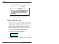
Setting the SCSI IDs
Default SCSI IDs are assigned at the factory for the autoloader
and the drive. This section describes how to view the default
settings and change them if necessary.
➤ Important
The autoloader and drive must
each have a unique SCSI ID.
To view or change the SCSI IDs:
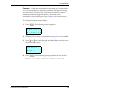
1. Press [MENU]. The following screen appears:
4 S e c u r
D
i
t y
s a b l e d
Note: If security is enabled, the second line of the LCD
displays LCD PW or SCSI (depending on what mode
was used to set security). If necessary, disable LCD
security, as described on page 42.
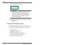
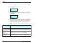
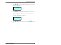
2. Press [3] or [4] to scroll through the Main Menu until you see
the following screen:
4 S C S I
D
0 1
A
0 0 E 1
§ D01– the current SCSI ID of the tape drive
§ A00– the current SCSI ID of the autoloader
§ E1– 210 emulation is on (1) or off (0)
34
Exabyte EZ17M and EZ17A
Configuration
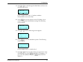
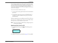
3. Press [ENTER]. The following screen appears:
4 S C S I
D
0 1
A
I D
0 0
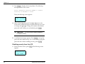
4. If you want to change the current settings, press [ENTER]. The
message Set SCSI IDs flashes on the screen, then the
following screen appears:
D 0 1
↕
A
0 0
→
5. To change the drive’s SCSI ID, press 3 or 4 until you see the
ID you want. Or, if you only want to change the autoloader’s
SCSI ID, press 2. The screen arrow moves to the far right digit
in the autoloader’s SCSI ID.
Note: Certain software applications require the autoloader
SCSI ID to be set one digit lower than the drive SCSI
ID. Refer to the documentation for your software
application for more information.
6. Press 3 or 4 until you see the SCSI ID you want for the
autoloader.
7. Press [ENTER].
8. If you changed the SCSI ID for the drive, the following
message flashes on the screen:
Power cycle the autoloader to change the drive
SCSI ID or press ESCAPE to cancel
Installation and Operation
35
Chapter 3
To keep the SCSI ID you set, power the autoloader off, wait
10 seconds, and then power it back on. If you do not want to
keep the tape drive SCSI ID, press [ESCAPE].
CAUTION
Wait at least 10 seconds between powering the
autoloader off and turning it back on again to
allow the drive sufficient time to complete its
reset operation.
Note: You do not need to power cycle the autoloader if you
only changed the autoloader’s SCSI ID.
Setting the Emulation mode
Use the 210 emulation mode if your application software does not
support the EZ17 and does support the Exabyte 210 library. When
emulation is on, the autoloader responds “EXB-210” to a SCSI
INQUIRY command. This allows you to use most (but not all)
application software packages that provide a driver for the
Exabyte 210 library but not for the Exabyte EZ17 autoloader.
To set the autoloader to Exabyte 210 emulation mode:
1. Press [MENU]. The following screen appears:
4 S e c u r
D
i
t y
s a b l e d
2. Disable LCD security, as described on page 42, if it is enabled.
36
Exabyte EZ17M and EZ17A
Configuration
3. Press 3 or 4 to scroll through the Main Menu until you see
the following screen:
4 S C S I
D
0 1
A
0 0 E 1
In the example above, the “E” indicates whether
210 emulation is on (1) or off (0).
4. Press [ENTER] to view the options in the SCSI Menu, if you
want to change the 210 emulation setting. The following
screen appears:
4 S C S I
D
0 1
A
I D
0 0
5. Press 3 or 4 until the following screen appears:
4 E m u l a t e
2 1 0
:
1
6. Press [ENTER] to view the emulation options. The following
screen appears:
E m u
l a t e
2 1 0 ?
n
↑
In the example above, n is either 0 or 1.
7. Press 3 or 4 until you see the setting you want. If you want
210 emulation on, press [ENTER] when the LCD displays 1. If
you want 210 emulation off, press [ENTER] when the LCD
displays 0.
Installation and Operation
37
Chapter 3
Setting the Robot Control mode
The robot control mode determines which interface is used to
control the motion of the robot. Robot control modes are
described below. After you select a control mode, it remains in
effect until you change it. Cycling the power or resetting the
autoloader does not change the control mode.
SCSI If you want the application software to control
autoloader operations, you must set the autoloader to SCSI mode.
In this standard operating mode, the application software
controls the motion of the robot by issuing SCSI commands across
the SCSI bus.
Note: The application software can issue commands to the
autoloader regardless of the robot control mode.
However, the autoloader must be in SCSI mode for the
application software to control the robot’s motion.
For detailed information about SCSI commands, refer to the
Exabyte EZ17 Autoloader SCSI Reference.
Sequential If you want the autoloader to run as a sequential
stacker device, you need to set the autoloader to Sequential mode.
In this mode, the application software does not need to provide
support for autoloader functions, only for the drive. For detailed
information about using Sequential mode, see page 53.
LCD If you want to perform operations from the operator panel
that involve moving the robot or connecting the serial port to the
drive, you need to set the autoloader to LCD mode. These
operations, such as exercising the autoloader’s components, and
communicating with the drive over the serial port, are included
under the Command Menu, the Demo Menu, or the Serial Menu.
38
Exabyte EZ17M and EZ17A
Configuration
Console When the autoloader is operating in Console mode,
you can download new firmware, perform a diagnostic listing,
and view the LCD password. Your host must have a remote
terminal emulation program and be connected to the
autoloader’s 9-pin serial port. (See Chapter 6 for instructions.)
To change the robot control mode:
1. Press [MENU]. The following screen appears:
4 S e c u r
D
i
t y
s a b l e d
2. Disable LCD security, as described on page 42, if it is enabled.
3. Press 3 or 4 to scroll through the Main Menu until you see
the following screen:
4 R o b o t
S C S I
4. Press [ENTER]. The following message flashes on the screen:
Select I/F that controls robotic motions
Installation and Operation
39
Chapter 3
Then, the following screen appears:
R o b o t ?
S C S I
↕
➤ Important
If you select Sequential mode, you
need to set the Loop and Restart options (see
page 56 for instructions). If you select Console
mode, you need to set the autoloader’s baud rate
to match the host computer’s baud rate (see
page 91 for instructions).
5. Press 3 or 4 until you see the control mode you want and
press [ENTER] to select it.
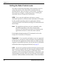
Setting the LCD Security option
The Security option allows you to prevent unauthorized
personnel from disrupting the operation of the autoloader. When
you enable security, the following activities are prevented:
§
§
§
§
§
§
§
40
Changing SCSI IDs
Changing the robot control mode
Changing 210 emulation
Unlocking and removing the magazine
Using the Command Menu and Demo Menu
Connecting the serial port to the drive
Changing Sequential mode options
Exabyte EZ17M and EZ17A
Configuration
If you attempt to perform any of the previous operations when
security is enabled, the autoloader displays a message indicating
that security is active. The message also indicates whether
security was enabled from the LCD or by the application software
with a SCSI command.
You can set security in either of two ways:
§ You can set the security option from the LCD, as described in
this section.
§ The application software can issue a SCSI MODE SELECT
command to enable or disable security (see your software
documentation).
Whichever method you use to enable security (LCD or SCSI), you
must also use it to disable security. That is, if you enable security
from the LCD, you must disable it from the LCD.
Note: The security setting is unaffected by cycling the power or
resetting the autoloader.
Enabling security from the LCD
1. From the Status screen, press [MENU]. The following screen
appears:
4 S e c u r
D
i
t y
s a b l e d
2. Disable LCD security, as described on page 42, if it is enabled.
Installation and Operation
41
Chapter 3
3. Press [ENTER] to display the Security Menu. The following
message flashes on the screen:
Select password and press ENTER to enable
security or ESCAPE to cancel
Then, the following screen appears:
P W ?
0 0 0
←
↕
→
4. Select a three-digit password. Press 1 or 2 to move the
screen arrow under the digit in the password that you want
to change and 3 or 4 to change the number. (The default
password is 000.) When you are finished, press [ENTER].
➤ Important
You must use the same password
to disable security.
5. A confirmation message appears. Press [ENTER] to accept the
password and enable security. Or, to exit without saving the
password and without enabling security, press [ESCAPE].
Disabling security from the LCD
1. From the Status screen, press [MENU]. The following screen
appears:
4 S e c u r
L C D
42
t y
P W
Exabyte EZ17M and EZ17A
Configuration
Note: If the menu displays Disabled, the security option is
already disabled. If the menu displays LCD PW,
security was enabled using the LCD as described in
the following steps. If the menu displays SCSI,
security was enabled by your application using a SCSI
command. If a SCSI command was used to enable
security, it must be used to disable security. Refer to
your software documentation for instructions.
2. Press [ENTER] to enter the Security Menu. The following
message flashes on the screen:
Enter password and press ENTER to disable
security or ESCAPE to cancel
Then, the following screen appears:
P W ?
0 0 0
←
↕
→
3. Enter the three-digit password you selected when you set
security. Press 1 or 2 to move the screen arrow under the
digit in the password that you want to change and 3 or 4 to
change the numbers. (The default password is 000.) When
you are finished, press [ENTER]. The following screen appears:
4 S e c u r
D
i
t y
s a b l e d
If you enter the wrong password, the system displays an error
message.
Installation and Operation
43
Chapter 3
Note: If you forget the password, try entering the default
password (000). If the password has been changed from
the default and you do not know what it is, see Chapter 6
for instructions about how to view the LCD password.
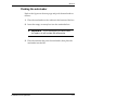
Checking the setup
After you install the hardware and software, check the setup by
performing the suggested exercises below. While these exercises
are not required, it is a good idea to verify that your software and
hardware are properly communicating before you begin
operations.
§ Use the Demo Menu to exercise the hardware. This
determines whether the autoloader hardware components
are operating properly. See “Using the Demo Menu” on page
69 for more information.
§ Use the application software to load and unload one or more
cartridges into the drive. This determines whether the
software, autoloader, and drive are communicating properly.
§ Back up several megabytes of data and perform a comparison
check on the backed up data. This determines whether the
software and drive are communicating properly.
If the autoloader and drive are not operating as expected, see
Chapter 7 for troubleshooting information. If there is an error
code displayed on the LCD, see Appendix C for a list of error
codes and corrective actions. If you cannot solve the problem
yourself, contact your service provider or Exabyte (see
“Contacting Exabyte” on the inside back cover).
44
Exabyte EZ17M and EZ17A
Configuration
Beginning autoloader operations
After you configure the autoloader, you are ready to perform
backup and restore operations. However, before you begin, check
the following:
§
§
§
§
The drive does not have a cartridge loaded.
The robot does not contain a cartridge.
The cartridge magazine is installed.
The autoloader is in the proper control mode. The standard
operating mode is SCSI (see page 38).
Installation and Operation
45
Chapter 3
Notes
46
Exabyte EZ17M and EZ17A
4
Autoloader Operation
This chapter describes the following autoloader operations you
may need to perform:
§
§
§
§
§
§
§
§
Removing and replacing the magazine
Storing cartridges
Operating the autoloader in Sequential mode
Setting Sequential mode options
Avoiding interruptions
Viewing autoloader information
Performing hardware exercises
Resetting the autoloader
Note: The application software automatically controls the
autoloader’s robotics to perform backup and restore
operations. You do not need to intervene in the cartridge
processing; however, you may need to occasionally
perform the tasks described in this chapter.
Installation and Operation
47
Chapter 4
Removing and replacing the magazine
This section describes removing and replacing the magazine to
access the cartridges and the drive.
Removing the magazine
To remove the magazine to access the cartridges or the drive,
follow these steps:
1. Release the magazine by pressing [REMOVE{{ { MAG] and follow the
instructions on the screen. When the autoloader finishes the
current operation, it parks the robot in front of the drive and
releases the magazine’s solenoid.
Note: Pressing [REMOVE{{ { MAG] parks the robot in front of the
drive. If you want to access the drive, use the Park &
Unlock command from the Main Menu.
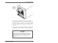
2. Grasp the magazine at the top (near cartridge slot 7) and pull
out, as shown in the following figure.
CAUTION
Do not force the magazine out of the autoloader.
Doing so may damage the magazine or the
robot.
48
Exabyte EZ17M and EZ17A
Autoloader Operation
Cartridge
magazine
slot 7
If the magazine does not release easily, the autoloader’s
security setting may be turned on or the robot’s gripper may
be holding a cartridge. Check the security setting and disable
security, if necessary (see “Disabling security from the LCD”
on page 42).
If you suspect the robot’s gripper is holding a cartridge, power
the autoloader off, wait 10 seconds, and then power it back
on.
CAUTION
Wait at least 10 seconds between powering the
autoloader off and turning it back on again to allow
the drive sufficient time to complete its reset
operation.
Installation and Operation
49
Chapter 4
Installing the magazine
To install the magazine after accessing the cartridges or the drive,
follow these steps:
➤ Important
Use only magazines designed for
the Exabyte EZ17M and EZ17A autoloader. Do not
use Exabyte magazines designed for other
Exabyte libraries.
Before installing the magazine, make sure there is
not a cartridge in the drive. If you install the
magazine when there is a cartridge in the drive, the
autoloader cannot complete its pow er-on self-test,
resulting in an error.
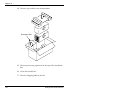
1. Position the magazine so the bottom mounting guide on the
magazine (near cartridge slot 1) aligns with the slot in the
bottom of the opening in the autoloader, as shown in the
following figure
CAUTION
Do not force the magazine into the autoloader.
Forcing the magazine may break the cartridge slot
fingers.
50
Exabyte EZ17M and EZ17A
Autoloader Operation
2. Push the top of the magazine until it snaps into place.
Installation and Operation
51
Chapter 4
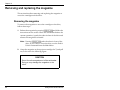
Storing cartridges
To maximize the shelf life of your cartridges and ensure data
integrity, follow the guidelines below when storing cartridges.
§ Store cartridges in a suitable environment. Follow the
specifications for storage temperature and other
environmental requirements, as described on the cartridge
packaging. Do not allow the temperature and humidity in the
storage environment to fluctuate.
§ Keep the storage location as free of airborne particulates as
possible. To eliminate obvious sources of particulates, do not
permit anyone to smoke, eat, or drink near the storage area,
and do not store cartridges near a copier or printer that may
emit toner and paper dust.
§ Store cartridges with the write-protect switch in the
protected position. See page 18.
§ Store cartridges as soon as possible after you remove them
from the autoloader. Immediate storage helps avoid many of
the conditions that can damage tapes, such as temperature
and humidity fluctuation, particulate contamination, and
excessive handling.
§ Store cartridges in a cartridge magazine, if possible. In the
cartridge magazine, cartridges are protected from airborne
contaminants by a plastic cover.
52
Exabyte EZ17M and EZ17A
Autoloader Operation
Operating the autoloader in Sequential mode
When the autoloader is operating in Sequential mode, its internal
firmware instructs the robot to move cartridges sequentially
between the cartridge slots and the drive. No application software
is required to support cartridge pick and place functions.
In Sequential mode, the autoloader performs the following steps:
1. Picks the cartridge from slot 1 and places it in the drive. If the
slot is empty, the robot picks the next cartridge in the
magazine.
2. Waits until the drive ejects the cartridge, then returns the
cartridge to its original slot.
3. Repeats these steps for the next cartridge until it has processed
all of the cartridges in the magazine.
4. Depending on how the Loop option is set, the robot either
returns to the first cartridge and begins the process again, or
stops. The Loop option is described in the following section.
Installation and Operation
53
Chapter 4
Sequential options
To customize how Sequential mode works, you can set the Loop,
Restart, and Next Cart options. These options are not affected by
a reset or power cycle.
Loop option
The Loop option determines what the autoloader does after it has
finished processing the last cartridge in the magazine. As shown
in the following table, the autoloader can either loop back to the
first cartridge in the sequence and start processing the cartridges
again or stop and wait for operator intervention. (Operator
intervention typically means removing the autoloader’s
magazine and inserting a new magazine.)
If Loop is...
The autoloader...
On
Returns to cartridge 1 and starts processing the
cartridges again.
Off
Stops processing cartridges and waits for operator
intervention.
Restart option
The Restart option determines where the autoloader restarts after
it is reset or power cycled, or after the magazine is removed and
replaced. The autoloader can restart either at the beginning of the
cartridge sequence or where it left off when the interruption
occurred.
54
Exabyte EZ17M and EZ17A
Autoloader Operation
As shown in the following table, the Restart option determines
what the autoloader does next.
If Restart is...
The autoloader...
On
Restarts at slot 1.
Off
Resumes where it left off.
Before the autoloader restarts Before restarting, the
autoloader performs the following actions:
1. The autoloader performs a power-on self-test (POST).
2. If the robot was moving a cartridge, it finishes the move. (This
includes inserting the cartridge into the drive if the robot was
moving a cartridge to the drive.)
Note: If you attempted to remove the magazine, the
autoloader does not release the magazine’s solenoid
until it has completed the move.
3. If a cartridge is in the drive, the following happens:
a. The robot waits for the drive to eject the cartridge, then
reseats the cartridge in the drive.
b. The autoloader initializes element status to check for
cartridges in the magazine.
c. The robot returns the cartridge to its original slot.
Installation and Operation
55
Chapter 4
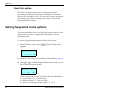
Next Cart option
The Next Cart option allows you to interrupt sequential
processing and specify that the next cartridge the autoloader
selects is the cartridge in slot 1. If you want to resume sequential
processing from the first cartridge, select Next Cart from the
Sequential Options Menu.
Setting Sequential mode options
This section describes how to set the Loop, Restart, and Next Cart
options after you have configured the autoloader to run in
Sequential mode.
To set the Sequential mode options, follow these steps:
1. From the Status screen, press [MENU]. The following screen
appears:
4 S e c u r
D
i
t y
s a b l e d
2. Disable LCD security if it is enabled, as described on page 42.
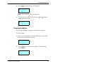
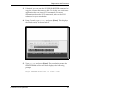
3. Press 3 or 4 to scroll through the Main Menu until you see
the Sequential Options screen:
4 S e q
L n
R n
O p t
N n
In the example above, each n has the value described below:
L – Loop option: n = 1 (on) or 0 (off).
R – Restart option: n = 1 (on) or 0 (off).
N – the next cartridge to be processed: n = 1 to 7.
56
Exabyte EZ17M and EZ17A
Autoloader Operation
4. Press [ENTER]. The Loop Option screen appears:
4 L o o p
O p
t
:
n
5. Press [ENTER] to display the screen for changing the Loop
option:
L o o p ?
0 ↑
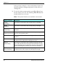
6. Press 3 or 4 until you see the setting you want. If you want
Loop on, press [ENTER] when the LCD displays 1. If you want
Loop off, press [ENTER] when the LCD displays 0. The Loop
Option screen shows the new setting.
7. Press [ENTER] to display the Restart Option screen:
4 R e s t a r t
O p
t
:
1
8. Press [ENTER] to display the screen for changing the Restart
option:
R e s
t a r
t ?
1 ↓
9. Press 3 or 4 until you see the setting you want. If you want
Restart on, press [ENTER] when the LCD displays 1. If you want
Restart off, press [ENTER] when the LCD displays 0. The Restart
Option screen shows the new setting.
Installation and Operation
57
Chapter 4
10. Press [ENTER] to display the Next Cartridge screen:
4 N e x t
C a r
t
:
n
In the example above, n is a number from 1 to 7.
If n is 1, the next cartridge the autoloader will process is the
cartridge in slot 1. You do not need to modify this setting.
If n is a number from 2 to 7 and you want the next cartridge
the autoloader processes to be the cartridge in slot 1, press
[ENTER]. The following message flashes on the screen:
Press ENTER to set next cart to 1 or ESCAPE to
cancel
11. Press [ENTER] again to set the next cartridge to 1.
12. Press [ESCAPE] to return to the Sequential Options screen.
58
Exabyte EZ17M and EZ17A
Autoloader Operation
Avoiding interruptions
Although the autoloader has effective methods for resuming
operation, it is best to avoid interruptions when the autoloader is
operating in Sequential mode. In particular:
§ Do not reset or power cycle the autoloader unless absolutely
necessary. Reset the autoloader only to clear certain
autoloader error conditions and power off the autoloader only
to perform maintenance or to store it. Avoid resetting or
power cycling the autoloader when a cartridge is in the drive
or the robot.
§ Do not remove the magazine unless absolutely necessary.
During operation, remove the magazine only after the
autoloader has processed all the cartridges. Never force the
magazine. The autoloader will not release the magazine until
it has completed a cartridge move or load already in progress.
Certain applications may also prevent the magazine from
being removed.
§ Do not remove a cartridge from the drive or insert a cartridge
into the drive. If you want to remove a cartridge, wait until
the robot has placed it in the magazine before removing it. If
you want to add a cartridge, add it directly to the magazine.
Installation and Operation
59
Chapter 4
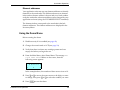
View ing autoloader information
The functions in the Autoloader Info Menu are mainly for use by
technical support and application developers. Technical support
may ask you to display one of these screens and locate
information to help troubleshoot a problem.
This section describes the following autoloader information:
§ Code Versions. Contains information about the flash code
level and the boot code level.
§ System Statistics. Contains information about robot
operations.
§ System Sensors. Contains information about the autoloader’s
mechanical sensors.
§ Inventory. Contains information about the elements.
View ing code versions
The Autoldr Info Menu contains information about the flash code
level and the boot code level.
To view code levels:
1. Select Autoldr Info Menu from the Main Menu, then scroll
until you see the following screen:
4 C o d e
V e
60
r s
i o n s
Exabyte EZ17M and EZ17A
Autoloader Operation
2. Press [ENTER]. The following screen appears:
< F
l
a s h
1
9
. 1
.
Note: Your code levels may be different.
3. To view the level of the boot code, press [3] or [4] until you
see the following screen:
< B o o t
0
.
0
. 6
View ing statistics
The Autoldr Info Menu contains a System Stats submenu.
To view statistics:
1. Select Autoldr Info Menu from the Main Menu, then scroll
until you see the following screen:
4 S y s t e m
S t a t s
2. Press [ENTER] to view the system statistics. The following
screen appears:
< M o v e s
n
Installation and Operation
61
Chapter 4
In the previous example, n is the total number of times the
robot has picked a cartridge and placed it in the drive or a
cartridge slot.
3. To view the other system statistics, press 3 or 4 until you
see the statistic you want. The following table describes the
system statistics you can view.
Note: The System Statistics are cumulative across resets.
System Statistics
Description
PickRet
(Pick Retry)
The number of times the robot retried picking a cartridge.
PutRet
(Put Retry)
The number of times the robot retried placing a cartridge.
ThetRe
(Theta Retry)
The number of times the robot retried to position itself on the
theta axis.
PwrCnt
The number of times the autoloader has been power cycled or
(Power Cycle Count) reset from the operator panel.
Loads
The number of times the robot loaded (pushed) a cartridge into
the drive.
Reloads
The number of times the robot reloaded the cartridge in the drive
because the drive ejected the cartridge too soon.
ShrtLds
(Short Loads)
The number of times the robot reloaded a cartridge into the
drive, either because the drive ejected the cartridge too soon
and the cartridge was not ejected far enough, or the cartridge
did not load completely into the drive on the first attempt.
DPckRet
(Drive Pick Retry)
The number of times the robot retried picking from the drive
because the drive did not eject the cartridge far enough.
62
Exabyte EZ17M and EZ17A
Autoloader Operation
View ing system sensors
The System Sensors screens enable you to troubleshoot hardware
problems by checking the current status of the autoloader’s
internal mechanical sensors.
To view system sensors:
1. Select Autoldr Info Menu from the Main Menu, then scroll
until you see the following screen:
4 S y s t e m
S e n s o r s
2. Press [ENTER] to view the system sensor information. The
following screen appears:
< M a g a z n e
L o c k e d : n
In the preceding example, n indicates whether the magazine
is locked (1) or unlocked (0).
Installation and Operation
63
Chapter 4
3. To view the other system sensors, press 3 or 4 until you see
the sensor you want. The following table describes the
remaining system sensors.
System sensors
Description
Magazne Presnt
Indicates whether the magazine is inserted in the autoloader (1)
(Magazine Present) or not (0).
Cart Ejectd
(Cartridge Ejected)
Indicates whether a cartridge is protruding from the drive (1) or
not (0).
Cart Seated
(Cartridge Seated)
Indicates whether a cartridge is seated in the robot (1) or not (0).
Slot Snsr
Provides feedback that helps the firmware track where the robot
is on its theta axis.
Theta Home
Indicates whether the robot is in its home position (1) or not (0).
Picker St
(Picker State)
Indicates the status of the robot’s picker mechanism, as follows:
64
07 –The picker is at home position (fully extended).
1f – The picker is in the tray position.
0a –The picker is extended (waiting for the cartridge to eject from
the drive).
0c –The picker is retracted.
0f – The picker is between the home position and the tray
position.
1e –The picker is between the tray position and the extended
position.
0e –The picker is between the extended position and the
retracted position.
Exabyte EZ17M and EZ17A
Autoloader Operation
View ing inventory information
The autoloader stores inventory information in nonvolatile RAM
and uses the information to process SCSI commands from the
application software. The inventory contains information about
the following element locations:
§ Cartridge slots
§ Tape drive
§ Robot
To view the Inventory Menu:
1. Select Autoldr Info Menu from the Main Menu, then scroll
until you see the following screen:
4 I
t
n v e n o r y
2. Press [ENTER] to view the inventory information. The
following screen appears:
I
n d e x ?
8 2
( n ) ↕
In the example above, n can be D, R, or S, as follows:
D – the drive
R – the robot
S – a cartridge slot
Installation and Operation
65
Chapter 4
3. Press 3 or 4 to select the element index you want to view.
Then press [ENTER]. The following table describes the
inventory information you can view about each element.
Inventory information
Element info
Description
Occup
(Occupied)
Indicates whether the autoloader considers the specified element
location to contain a cartridge (1) or not (0).
Valid
(Occupied Valid)
Indicates whether the Occupied flag is accurate (1) or questionable
(0).
Access (Tape
Drive Accessible)
Indicates whether a cartridge is loaded in the drive (0) or the drive
is empty or the cartridge is ready to be picked (1).
Present
(Cartridge
Magazine, Tape
Drive Present)
Indicates whether the magazine or drive is installed (1) or not (0).
If the element index references a storage element, this flag
indicates whether the magazine is installed. If the element index
references the drive, this flag indicates the drive is installed.
Note: The Present flag is always 1 for the robot.
Warning
Shows if there are any errors for the specified element index. (See
Appendix C for a list of error codes and corrective actions.)
Source (Source
Element Index)
Shows the index of the last storage element from which a cartridge
was moved.
Theta
Shows the theta axis position in steps from the home position.
Address
Shows the SCSI element address of the specified element.
66
Exabyte EZ17M and EZ17A
Autoloader Operation
Inventory information (continued)
Element info
Description
Rsrv (Reserved)
The element is reserved by a host (1) or not (0).
Host
The SCSI ID of the host that is reserving the element.
Reserve ID
The ID that the element is reserved under. This is a number
assigned to the element by a host when the reservation was made.
TotPuts
Total Puts)
Shows the total times the robot tried to put to that element since
the last reset.
PckRety
(Pick Retry)
Shows the total times the robot retried to pick from that element
since the last reset.
PutRety
(Put Retry)
Shows the total times the robot retried to put to the element since
the last reset.
Performing hardware exercises
This section describes how to perform hardware exercises using
the Demo Menu and Command Menu from the operator panel.
Both of these menus are available from the Main Menu. The Demo
Menu causes the robot to randomly move cartridges between
slots. The Command Menu provides options for specific robot
movements.
Using elements
Elements are the physical locations in the autoloader that can
accept a cartridge (the robot, the magazine slots, and the drive).
Installation and Operation
67
Chapter 4
Element indexes
Each element has an element index, which enables the autoloader
to identify the elements. Many LCD functions require you to use
element indexes. For example, to move a cartridge using the
Command Menu, you must specify the source and destination
element indexes. The source is either the drive or a cartridge slot
where the robot will pick a cartridge. The destination is either the
drive or a cartridge slot where the robot will place the cartridge.
The following figure shows the element indexes assigned for the
autoloader.
Robot
Tape Drive
Data cartridge
magazine
Data cartridge
slot
68
Exabyte EZ17M and EZ17A
Autoloader Operation
Element addresses
Your application software may use element addresses to identify
elements in the autoloader. The difference between an element
index and an element address is that an index is a fixed number
set by the autoloader, whereas an address can be changed by your
application software (using the SCSI MODE SELECT command).
The element indexes correspond to the autoloader’s default
element addresses. The element addresses are displayed in the
Inventory Menu.
Using the Demo M enu
Before running the demo:
1. Disable security if it is enabled (see page 42).
2. Change the control mode to LCD (see page 39).
3. Verify that there is at least one cartridge present and one
empty slot before you begin the test.
4. From the Main Menu, select Demo Menu. The message Set
total demo moves flashes on the screen, then the
following screen appears:
0 0 0 0 0 1 0
←
↕
→
In the example above, the number of demo moves is set to 10.
5. Press 3 or 4 to move the screen arrow to the digit you want
to change, then press 3 or 4 to select the number you want.
6. Press [ENTER] to start the demo.
Installation and Operation
69
Chapter 4
Using the Command M enu
To perform hardware exercises and inventory checks:
1. From the Main Menu, select Command Menu. The following
screen appears:
4 M o v e
C a r
t
2. If you want to move a cartridge, press [ENTER]. If you want to
perform other exercises, press 3 or 4 until you see the
exercise you want to perform and then press [ENTER].
The following table describes each exercise and provides
additional instructions for performing the tests (if applicable).
Test
Description
Additional instructions
Move Cart
(Move
Cartridge)
Moves a cartridge from one
location to another.
When you select Move Cart, the
Move Src? screen appears.
Press 3 or 4 to select the
source index (the slot you want
the robot to pick from), then
press [ENTER].
The Move Dest?screen appears.
Press 1 or 2 to select the
destination index (the slot where
you want the robot to place the
cartridge), then press [ENTER].
Important: Do not load a
cartridge in the drive. The drive
will not automatically eject the
cartridge.
Init Element
Performs an inventory of the
(Initialize
cartridges.
Element Status)
70
Exabyte EZ17M and EZ17A
Autoloader Operation
Test
Description
Additional instructions
Pos to Element
(Position to
Element)
Positions the robot in front of the
drive or a magazine slot.
When you select Pos to Element,
the Pos Elem Dest? screen
appears. Press 1 or 2 to select
the element index where you
want to position the robot, then
press [ENTER].
Self Test
Cycles the robot and picker
through their entire ranges of
motion once.
Park
Moves the robot to the top of the
autoloader.
Home Robot
Moves the robot to its home
position in front of the drive.
Cycle Pick/Put
Causes the robot to take a
cartridge from a specified
element and replace it in the same
location the number of times you
requested.
Cycle Theta
Moves the robot up and down the When you select Cycle Theta,
number times you requested.
the message Select number
of test cycles flashes on
the screen. Press 1 or 2 to
move the screen arrow to the
digit you want to change. Then,
press 3 or 4 to select the
number of cycles you want this
test to run and press [ENTER].
Installation and Operation
When you select Cycle Pick/Put,
the Cycle PP Src? screen
appears. Press 1 or 2 to select
the source index (where you
want the robot to pick and put
the cartridge) and press [ENTER].
The message Select number
of test cycles flashes on
the screen. Press [1] or [2] to
move the screen arrow to the
digit you want to change. Then,
press 3 or 4 to select the
number of cycles you want this
test to run and press [ENTER].
71
Chapter 4
Test
Description
Additional instructions
Cycle Reach
Causes the following:
When you select Cycle Reach,
the message Select number
of test cycles flashes on
the screen. Press 1 or 2 to
move the screen arrow to the
digit you want to change. Then,
press 3 or 4 to select the
number of cycles you want this
test to run and press [ENTER].
§ The robot to move to its home
position on the theta axis
§ The picker to move to the
extended position, to the
retracted position, and back to
the extended position
Cycle Solenoid
Exercises the solenoid that
controls the locking mechanism
on the magazine the number of
times you requested.
When you select Cycle
Solenoid, the message Select
number of test cycles
flashes on the screen. Press 1
or 2 to move the screen arrow
to the digit you want to change.
Then, press 3 or 4 to select the
number of cycles you want this
test to run and press [ENTER]. You
will hear a click each time the
solenoid extends and retracts.
Resetting the autoloader
If the autoloader has encountered an error and is still not
operating after you have tried the recommended corrective
action for the error, you may need to reset the autoloader. A reset
causes the autoloader to perform its power-on self-test.
CAUTION
Before resetting the autoloader, make sure
it is not communicating across the SCSI
bus. Resetting the autoloader may disrupt
communications on the SCSI bus.
72
Exabyte EZ17M and EZ17A
Autoloader Operation
To reset the autoloader, use one of the following methods:
§ Press [RESET] on the operator panel, then press [ENTER] at the
confirmation screen (or press [ESCAPE] to cancel).
§ Perform a power-on reset by powering the autoloader off,
waiting 10 seconds, then powering it back on.
CAUTION
Wait at least 10 seconds between powering the
autoloader off and turning it back on again to
allow the drive sufficient time to complete its
reset operation.
When the power-on self-test is complete, the Status screen
appears on the LCD.
Note: If the autoloader is performing a cartridge move operation
when it is reset, it attempts to complete the move
operation after it performs the power-on self-test.
Installation and Operation
73
Chapter 4
Notes
74
Exabyte EZ17M and EZ17A
5
Tape Drive Operation
The application software automatically controls the drive to
perform backup and restore operations. Normally, you do not
need to intervene in the cartridge processing; however, you may
occasionally want to perform the following tasks:
§
§
§
§
§
Cleaning the drive
Resetting the drive
Displaying information about the drive
Monitoring the drive LEDs
Ejecting a cartridge manually
Note: You cannot control the drive operation from the
autoloader’s operator panel.
Installation and Operation
75
Chapter 5
Cleaning the drive
Clean the drive whenever the autoloader displays ClnSoon on
the Status screen or whenever your application software notifies
you. (Not all software applications display cleaning
requirements.) Regular cleaning helps ensure that the drive
functions reliably. If MustCln appears on the Status screen, the
drive will not perform write or read functions until it is cleaned.
If your autoloader includes an M2 drive and you use AME with
SmartClean cartridges exclusively, your drive will automatically
perform the cleaning operation without any user intervention. If
you do not use SmartClean cartridges exclusively, your M2 will
require regular cleaning as described in the following sections.
If your autoloader includes a Sony AIT-2 drive, use cleaning
cartridges specifically designed for AIT drives. The AIT drives
should only require regular cleaning if your autoloader is
operating in extreme environmental conditions.
Note: Some software applications automatically perform drive
cleaning. If your application software supports automatic
cleaning, store a cleaning cartridge in the magazine slot
specified by the application. Refer to the documentation
for your software.
Follow these steps to manually clean the drive:
1. Park the robot and remove the magazine as described on
page 48.
2. Insert the cleaning cartridge into the drive. The drive
automatically performs the cleaning process and ejects the
cartridge when the process is complete.
76
Exabyte EZ17M and EZ17A
Tape Drive Operation
3. Remove the cleaning cartridge from the drive.
CAUTION
Do not touch the Magazine Present sensor when
inserting or removing the cleaning cartridge.
EN
TE
ME
RE
R
NU
SE
T
ES
CA
PE
STA
TU
S
RE
MO
MA VE
G.
Magazine present
sensor
4. Confirm that the cleaning was completed by looking at the
autoloader’s LCD. The ClnSoon or MustCln message should
be gone.
Installation and Operation
77
Chapter 5
If the LCD still displays ClnSoon or MustCln, replace the
cleaning cartridge and clean the drive again. If the message is
still on the autoloader LCD, or the drive LEDs are still on after
the second cleaning, there may be a problem with the drive.
➤ Important
If the drive ejects the cleaning
cartridge immediately after loading it and the LCD
displays the message Depleted, you need to
replace the cleaning cartridge. To order cleaning
cartridges, contact Exabyte (see “ Contacting
Exabyte” on the inside back cover).
5. Replace the cartridge magazine.
➤ Important
Before reinstalling the magazine,
make sure there is not a cartridge in the drive. If
you install the magazine when there is a cartridge
in the drive, the autoloader cannot complete its
power-on self-test and will display an error.
78
Exabyte EZ17M and EZ17A
Tape Drive Operation
Resetting the drive
If the drive has encountered an error and is still not operating after
you have tried the corrective action for the error, you may need
to reset the drive. Areset causes the drive to perform its power-on
self-test.
To reset the drive, power the autoloader off, wait 10 seconds, and
then power it back on.
CAUTION
Wait at least 10 seconds between powering the
autoloader off and turning it back on again to
allow the drive sufficient time to complete its
reset operation.
Note: Pressing [RESET] on the operator panel does not reset the
drive.
Displaying information about the drive
From the operator panel, you can display information about the
drive. The information screen is updated whenever there is a
change in drive status.
To display drive information:
1. Press [MENU]. The following screen appears:
4 S e c u r
D
Installation and Operation
i
t y
s a b l e d
79
Chapter 5
Note: It is not necessary to disable security to view drive
information.
2. Press 3 or 4 until the following screen appears:
4 D r
I
n
i
v e
f o
3. Press [ENTER] to display the Drive Info Menu. The following
screen appears:
4 D r
i
v e
S t a t u s
4. If you want to view drive status information, press [ENTER] to
display the Drive Status screen. The following table lists the
information displayed on the LCD’s Drive Status screen.
Note: Not all of these fields are available for AIT-2 drives.
Status
Description
Type
Displays the type of drive installed.
Serial#
Displays the serial number of the drive.
BootVer
(Boot Version)
Displays the code level of the drive’s boot ROM.
FlshVer
(Flash Version)
Displays the code level of the drive’s flash EPROM.
Needs Clean
Indicates whether the drive is clean (0) or needs to be cleaned
(1).
80
Exabyte EZ17M and EZ17A
Tape Drive Operation
Status
Description
Cart St
(Cartridge Status)
Displays the status of the cartridge, if any, in the drive:
Loaded – A cartridge is in the drive and the tape is loaded into
the tape path.
Loading – A cartridge is being loaded into the drive.
Unloading – A cartridge is being unloaded from the drive.
Present – A cartridge is in the drive, but the tape is not loaded
in the tape path.
Empty – The drive does not contain a cartridge.
Format
Displays the data format of the cartridge currently in the drive.
Present
Indicates whether a drive is installed (1) or not (0).
Occupid (Occupied)
Indicates if a cartridge is loaded in the drive (1) or not (0).
OccVald
(Occupied Valid)
Indicates if the occupied information is reliable (1) or not (0).
Access
Indicates if the drive is accessible to the robot (1) or not (0).
5. To view additional drive information, press 4 from the Drive
Info Menu and then press [ENTER] to display the Drive Display
screen. The following screen appears:
4 D r
D i
Installation and Operation
i
v e
s p l a y
81
Chapter 5
The following table lists some messages that can appear for the
M2, Mammoth, and Mammoth-LT tape drives. For a complete list,
refer to your drive’s installation and operation manual, available
in PDF format from www.exabyte.com.
M 2, M ammoth, and Mammoth-LT drive display messages
Tape drive status messages
READY–NOTAPE The drive is ready to accept a cartridge.
LOADING . . . .
The drive is loading the tape.
READY–TAPE
The drive has successfully loaded the tape and is ready for
read/write operations.
EJECT
The unload button was pressed. The drive ejects the cartridge as
soon as it finishes its current operation.
EJECT–PREVNT
The software has disabled the eject function with the
PREVENT/ALLOW MEDIA REMOVAL command. The drive will
rewind and unload the tape, but will not eject the cartridge.
ILLEGAL TAPE
The drive detected an incompatible cartridge and ejected it.
Tape motion messages
READ +
WRITE+
The drive is reading or writing data. The + sign appears when the
drive is in compression mode.
PROTECTED
The drive cannot write data because the data cartridge is
write-protected.
ILLEGAL WRT
The drive cannot write to the type of data cartridge inserted. This
message remains until an unload/eject operation is performed.
SEARCH
High-speed search is in progress.
REWIND
Rewind is in progress.
ERASE
The drive is erasing data on the tape.
82
Exabyte EZ17M and EZ17A
Tape Drive Operation
M 2, M ammoth, and Mammoth-LT drive display messages
Drive display messages
FORMAT
The drive is repartitioning the tape to the requested format.
WORN TAPE
The tape currently in the drive has exceeded the drive’s maximum
tape passes threshold and must be replaced.
Cleaning messages
CLEAN SOONa
The drive should be cleaned at the next convenient time.
CLEANING...
Cleaning is in progress.
DEPLETED
The cleaning tape in the cartridge is depleted and the drive will eject
it. Use a new cleaning cartridge.
CODE LOAD FAIL These messages appear in sequence after the code load failed.
RETRY CODE
LOAD
MAKE
CODELOAD TP
a
The drive is making a code load tape.
These messages appear when non-SmartClean media is used and the drive is cleaned using an Exabyte
Mammoth Cleaning Cartridge.
Installation and Operation
83
Chapter 5
The following table lists some messages that can appear for the
AIT-2 tape drive.
AIT-2 drive display messages
Tape drive status messages
RdyNoTpe
(Ready-no tape)
The drive is ready to accept a cartridge.
Loading
The drive is loading the tape.
Rdy-Out
(Ready out)
The cartridge is ejected from the drive.
RdyTape
The drive has successfully loaded the tape and is ready for
read/write operations.
(Ready tape)
Tape motion messages
Reading
The drive is reading or writing data.
Writing
TpMtion
The drive is moving tape.
(Tape in motion)
Unloadg
The drive is unloading tape.
(Unloading)
Cleaning messages
MustCln
The drive should be cleaned at the next convenient time.
(Must clean)
Clning
Cleaning is in progress.
(Cleaning)
84
Exabyte EZ17M and EZ17A
Tape Drive Operation
M onitoring the drive LEDs
➤ Important
You must park the robot and
remove the cartridge magazine as described on
page 48 before you can view the drive’s LEDs.
The drive faceplate has three LEDs for indicating the drive’s
operational status.
The following tables show the most frequent LED states and the
conditions they indicate. You may see other LED activity (random
flashing, steady on, and so forth). For a detailed description of the
LEDs, refer to the installation and operation manual for your
drive.
M 2, M ammoth, and Mammoth-LT LEDs
a
LED states
Condition
All LEDs on
The drive was reset or it is performing its
power-on self-test.
Top LED on
The drive requires cleaning or a cleaning
is in progress.a
Top LED flashing
Hardware error or the drive failed POST.
Middle LED on
A tape is loaded and the drive is ready to
perform tape motion activities.
Bottom LED flashing
Tape motion. A fast flash indicates
high-speed tape motion.
For M2 only, manual cleaning is required when standard AME media has been used.
Cleaning is automatic when AME with SmartClean cartridges are used exclusively.
Installation and Operation
85
Chapter 5
AIT-2 LEDs
a
LED states
Condition
Busy (left) LED on
SCSI activity is occurring.
Tape (middle) LED on
Tape is loaded.
Status (right) LED on
Cartridge is write-protected.
Tape LED is flashing
(3.5 seconds on;
0.5 seconds off)
Error has occurred.
Tape LED is flashing
(0.25 seconds on;
0.25 seconds off)
Tape is loading or unloading.
Status LED is flashing
(3.5 seconds on;
0.5 seconds off)
Cleaning required.a
Manual cleaning is required when the drive has been operating in extreme
environmental conditions.
Ejecting a cartridge manually
If a problem occurs that requires intervention, you may need to
manually eject a cartridge from the drive. Manually remove a
cartridge as follows:
1. Park the robot and remove the magazine, as described below:
a. From the Main Menu, press 3 or 4 until the following
screen appears:
4 P a r k
U n
86
&
l o c k
Exabyte EZ17M and EZ17A
Tape Drive Operation
b. Press [ENTER]. The following message flashes on the screen:
Unlock Magazine Yes:ENTER No:ESCAPE
c. Press [ENTER] to unlock the magazine. The robot parks at
the top of the autoloader and the magazine’s solenoid
releases.
d. Grasp the magazine at the top (near cartridge slot 7) and
pull out.
CAUTION
Do not force the magazine out of the autoloader.
Doing so may damage the magazine or the robot.
2. Press the eject button on the drive’s faceplate.
CAUTION
Do not touch the Magazine Present sensor when
pressing the eject button.
3. Remove the cartridge from the drive.
Installation and Operation
87
Chapter 5
The following figures show the location of the eject button on the
drives.
Eject button
Mammoth and Mammoth-LT drive faceplate
Eject button
M2 drive faceplate
BUSY
TAPE
STATUS
EJECT
Eject
button
AIT-2 drive faceplate
88
Exabyte EZ17M and EZ17A
6
Diagnostics and Firmware
This chapter describes how to do the following:
§
§
§
§
§
Connect to the Console interface
Upgrade autoloader firmware via Console
Create a diagnostic listing via Console
View the LCD password via Console
Communicate with the tape drive
This chapter uses the following conventions:
§ Keys shown boldfaced in brackets (for example, [Enter]), are
keys you press on your host computer’s keyboard.
§ Words shown in Courier, for example help, are commands
you type.
Installation and Operation
89
Chapter 6
Connecting to the Console interface
This section describes how to access the Console interface, the
autoloader’s internal diagnostics firmware. You can use Console
for upgrading firmware, creating a diagnostic listing, and viewing
the LCD password.
Before accessing Console, you must have the following:
§ A 9-pin straight-through serial cable (not a null modem cable)
§ A host computer that uses an RS232 serial port
§ Terminal emulation software, such as HyperTerminal
Note: Exabyte recommends using HyperTerminal, a standard
communications package available with Microsoft
Windows® .
Connecting the serial cable
1. Power off the autoloader and disconnect the power cord.
2. Connect the 9-pin cable to the back of the autoloader and to
the host computer. The following figure shows the location of
the 9-pin serial port on the back of the autoloader.
90
Exabyte EZ17M and EZ17A
Diagnostics and Firmware
3. Connect the power cord and power on the autoloader.
9-pin serial port
Setting the autoloader’s baud rate
Before accessing Console, you must set the baud rate for the
autoloader so that it matches the host computer’s baud rate.
To set the autoloader’s baud rate:
1. From the Main Menu, scroll until you see the following screen:
4 S e r
A
i a l
n n n n n
2. In the example above, nnnnn is the current baud rate for the
autoloader.
Installation and Operation
91
Chapter 6
3. To change the autoloader’s baud rate, press [ENTER]. The
following screen appears:
4 B a u d R a t
n n n n n
4. Press [ENTER]. The following message flashes on the screen:
Select serial port baud rate for Auto Loader
Then, the following screen appears:
B a u d ?
1 1 5 2 0 0 ↕
5. Press 3 or 4 until you see the baud rate that matches the
baud rate set on the host, and then press [ENTER].
Accessing Console using HyperTerminal
Note: These instructions assume you are using HyperTerminal,
a communications package available with Microsoft
Windows. If desired, you can use a different terminal
emulation software package.
To access Console using HyperTerminal:
1. From your computer, launch HyperTerminal.
2. In HyperTerminal’s Connection Description screen, enter a
name and choose an icon for this communications session.
3. In HyperTerminal’s Connect To screen, choose the
communications port you are using from the Connect Using
field. Click OK.
92
Exabyte EZ17M and EZ17A
Diagnostics and Firmware
4. In the Properties screen, make sure the fields contain the
following values, then click OK.
§
§
§
§
§
Bits per second: (baud rate of the computer)
Data bits: 8
Parity bits: none
Stop bits: 1
Flow control: none
5. Check the ASCII setup from HyperTerminal:
a. From the File menu, select Properties.
b. In the Properties screen, select the Settings tab.
c. In the Emulation mode field, select “ANSI.”
d. Click on the ASCII Setup button.
e. In the ASCII Setup screen, make sure none of the boxes
have check marks. Uncheck the boxes, if necessary.
f.
Click OK in the ASCII Setup screen.
g. Click OK again in the Properties screen.
6. The Console program should now appear in HyperTerminal’s
main window. If necessary, type redraw and then press
[Enter] to refresh the screen.
Installation and Operation
93
Chapter 6
7. If desired, type help and then press [Enter] to display
Console’s Help screen, as shown in the following figure.
Note: If garbled characters or no characters appear on the screen,
make sure you have the same baud rate set for the host as
you do for the autoloader.
Setting the autoloader to Console mode
Set the autoloader to Console mode by following these steps:
1. Press [MENU]. The following screen appears:
4 S e c u r
D
i
t y
s a b l e d
2. Disable LCD security if it is enabled, as described on page 42.
94
Exabyte EZ17M and EZ17A
Diagnostics and Firmware
3. Press 3 or 4 to scroll through the Main Menu until you see
the following screen:
4 R o b o t
S C S I
4. Press [ENTER]. The following message flashes on the screen:
Select I/F that controls robotic motions
Then, the following screen appears:
R o b o t ?
S C S I
↕
5. Press 3 or 4 until you see Console and press [ENTER] to select
it.
Installation and Operation
95
Chapter 6
Upgrading firmware via Console
These instructions describe how to upgrade the autoloader
firmware using the Console.
CAUTION
Do not upgrade firmw are unless Exabyte Technical
Support has advised you to do so. If performed
improperly, the upgrade procedure can render your
device inoperable. Consult with Exabyte Technical
Support before performing an upgrade.
Because of memory limitations, the autoloader
cannot validate the new firmware data before erasing
and reprogramming the flash EEPROM. If the
checksum calculated by the autoloader does not
match the embedded checksum, the new firmw are
will be unusable. Therefore, before performing the
write firmware operation, use the READ BUFFER or
READ FIRMWARE SCSI command to create a copy of
your current firmware.
To upgrade the autoloader firmware:
1. Obtain new firmware for the library. You can download new
firmware from Exabyte’s web site (www.exabyte.com), or you
can contact Exabyte Technical Support.
2. Access Console by following the steps in “Connecting to the
Console interface” on page 90.
96
Exabyte EZ17M and EZ17A
Diagnostics and Firmware
3. If desired, you can use the SCSI READ BUFFER command to
copy the current firmware to disk. To do this, use a software
application that can issue SCSI commands. For more
information about the SCSI commands, refer to the SCSI
reference for your autoloader.
4. From Console, type flash and press [Enter]. This displays
the Flash screen, as shown below.
5. Type pflash and press [Enter]. The autoloader erases the
flash EEPROM sectors and then displays the following
prompt:
Begin XMODEM download of flash code.
Installation and Operation
97
Chapter 6
6. Use your terminal emulation software to specify the source
location (path and filename) of the new firmware. For
HyperTerminal, follow these steps:
a. Select the Transfer menu.
b. Select Send File.
c. In the Send File screen, enter the path and file name of the
firmware or click on the Browse button to locate the file.
Select XModem as the protocol.
d. Click on Send.
The system initiates the firmware upgrade and displays its
progress on the screen. When the upgrade is successfully
completed, the autoloader resets.
CAUTION
Do not attempt to perform autoloader operations
or pow er dow n the autoloader until after the
autoloader automatically resets.
98
Exabyte EZ17M and EZ17A
Diagnostics and Firmware
Creating a diagnostic listing via Console
If you report a problem to Exabyte Technical Support, you may
be asked to create an autoloader diagnostic listing (also called a
dump) via the Console interface. A diagnostic listing is created
when you use a terminal emulation program (such as
HyperTerminal) to send an ASCII text copy of the diagnostic
buffer from the autoloader to the host computer. This buffer
information can be used by support personnel to troubleshoot
incidents with the autoloader.
Note: These instructions assume you are using HyperTerminal,
a communications package available with Microsoft
Windows. If desired, you can use a different terminal
emulation software package.
To create a diagnostic listing:
1. Access Console by following the steps in “Connecting to the
Console interface” on page 90.
2. Type dump and press [Enter].
3. Select the Transfer menu, then select Capture Text.
4. In the Capture Text screen, enter the path and filename for
the ASCII text file and press [Enter].
5. Press [Enter] again to start transferring the ASCII text file.
6. When the transfer is complete, select the Transfer menu, then
select Capture Text and Stop.
Installation and Operation
99
Chapter 6
View ing the LCD password via Console
You can view the LCD password from the Configuration
Information screen in the Console interface.
To view the LCD password:
1. Access Console by following the steps in “Connecting to the
Console interface” on page 90.
2. Type config, then press [Enter]. The Configuration
Information screen appears, as shown below. The password
appears next to the LCD password field.
100
Exabyte EZ17M and EZ17A
Diagnostics and Firmware
Communicating w ith the tape drive
These instructions describe how to establish communications
with the M2, Mammoth, or Mammoth-LT tape drive using the
autoloader’s serial port and Exabyte’s Monitor Software for
Windows program, so you can upgrade the drive firmware or
create a diagnostic listing.
Note: If you need to establish communications with an AIT-2
drive, contact Exabyte Technical Support or go to the Sony
web site at:
www.storagebysony.com/support/consumer.asp
Setting up the hardw are and softw are
Obtain the following:
§ A host computer that uses an RS232 serial port.
§ A straight-through 9-pin serial cable (not a null modem cable).
§ Windows 95, 98, 2000, or NT 4.0.
§ The M2 or Mammoth Monitor program. Exabyte provides a
Windows-based drive monitor software program that you can
download from Exabyte’s web side (www.exabyte.com) or
request from Exabyte Technical Support.
Note: If you will be upgrading drive firmware, you can
download new firmware from Exabyte’s web site
(www.exabyte.com) or you can contact Exabyte Technical
Support for firmware.
Installation and Operation
101
Chapter 6
Establishing drive communication
To establish communication with the drive over the autoloader’s
serial port:
1. Connect the serial cable to the autoloader and host computer
(see page 90).
2. Disable security if it is enabled (see page 42).
3. Set the autoloader to LCD mode (see page 39).
Note: If the autoloader is in an error state or if the magazine
is removed, you can connect the serial port to the drive
even if the autoloader is not in LCD mode.
4. From the Main Menu, press 3 or 4 until you see the
following screen:
4 S e r
A
i a l
n n n n n
In the above example, nnnnn is the current baud rate for the
autoloader.
5. Press [ENTER]. The following screen appears:
4 B a u d R a t
n n n n n
6. Press 3 or 4 until you see the following screen:
4 C o n n e c t
t
102
o
D r
i
v e
Exabyte EZ17M and EZ17A
Diagnostics and Firmware
7. Press [ENTER]. The following message flashes on the screen:
Connect serial port to drive?
Press [ENTER] to connect the serial port to the drive.
➤ Important
When you connect the serial port to
the drive, the autoloader automatically sets the
serial port baud rate to 9600. You must also set the
terminal emulation program’s baud rate to 9600.
Note: While the serial port is being used to communicate
with the drive, the following message flashes on the
screen:
Press ENTER to return serial port connect
to Auto Loader
You cannot perform other LCD operations until you
connect the serial port to the autoloader.
8. When you are ready to resume autoloader operations, press
[ENTER] to disconnect the serial port from the drive.
Installation and Operation
103
Chapter 6
Using the M2 or M ammoth M onitor softw are
To use the M2 or Mammoth Monitor software:
1. If necessary, download the M2 or Mammoth Monitor software
from Exabyte’s web site. Make sure you download the version
that matches your operating system.
Note: The Mammoth Monitor software is for both Mammoth
and Mammoth-LT. The M2 Monitor software is only
used with M2. Make sure you download the correct
software for your drive.
2. Install the M2 or Mammoth Monitor on your host computer
and then launch the software.
3. Refer to the Help file provided with the monitor software for
instructions on setting up and using the program, or to upload
firmware and perform diagnostics.
CAUTION
Do not upgrade firmware unless Exabyte Technical
Support has advised you to do so. If performed
improperly, the upgrade procedure can render your
device inoperable. Consult with Exabyte Technical
Support before performing an upgrade.
104
Exabyte EZ17M and EZ17A
7
Troubleshooting
This chapter provides a list of suggestions for solving problems
that may occur when you are installing and operating the
autoloader and the enclosed drive. The instructions in this chapter
are basic troubleshooting guidelines. For more advanced
troubleshooting, contact your service provider or Exabyte
Technical Support.
This chapter is divided into the following sections:
§ Problems with autoloader installation
§ Problems with drive operation
§ Problems with autoloader operation
Note: If an error code is displayed on the LCD, refer to
Appendix C. If the LEDs on the drive are flashing, see
page 85.
Installation and Operation
105
Chapter 7
Problems w ith autoloader installation
If your autoloader and application software are not
communicating after installation, check the following:
✔
SCSI IDs. Make sure that the SCSI IDs you selected for the
drive and autoloader are not the same as an ID used by any
other SCSI device on that bus, including the SCSI adapter card.
Refer to page 34 for information about setting the SCSI IDs.
✔
SCSI cabling. Make sure that all SCSI cables are securely
connected at both ends.
✔
Single-ended, LVD, and HVD devices. Make sure all devices
on the bus are all single-ended or LVD or all differential. You
can connect single-ended and LVD devices to the same bus.
However, mixing the two types of devices results in all devices
on the bus operating as single-ended devices. These devices
include the controller cards, cables, and terminators.
CAUTION
Connecting a single-ended or LVD device to an
HVD SCSI bus may hang the SCSI bus.
106
✔
SCSI cable lengths. Make sure the SCSI cabling does not
exceed maximum lengths (see page 126).
✔
Termination. Make sure your bus is properly terminated as
described on page 22. Make sure that you use the correct
terminator (see page 127). If another SCSI device previously
terminated the SCSI bus and is no longer at the physical end
of the bus, be sure to remove the terminators from that device.
Exabyte EZ17M and EZ17A
Troubleshooting
✔
Compatibility. Make sure that your drive and autoloader are
compatible with the application software you plan to use. Visit
Exabyte’s website at www.exabyte.com for compatibility
information.
✔
SCSI adapter card installation. Make sure that you installed
your SCSI adapter card correctly. Refer to the documentation
that came with your card for installation and troubleshooting
instructions. Pay special attention to steps describing setting
various jumpers and switches on the card. Make sure that the
card is properly seated.
✔
Software installation. Make sure that your application
software is installed and configured correctly. Refer to the
documentation that came with your software. Pay special
attention to steps describing configuring the software for use
with the autoloader and drive.
✔
Control mode. Make sure the autoloader is operating in the
correct control mode. For most applications, the control mode
should be set to SCSI mode. See page 38 for more information.
After checking the items above, reset the autoloader as described
on page 72.
Installation and Operation
107
Chapter 7
Problems w ith drive operation
If you have been successfully operating the application software
and autoloader in the past, but are now experiencing problems
reading and writing data, check the following:
108
✔
Write-protect switch. If you are writing data, make sure the
cartridge is write enabled (see page 18).
✔
Cartridge type. Use the appropriate cartridges for your drive.
See “Selecting cartridges” beginning on page 11 for
information about selecting the appropriate cartridges for the
drive in your autoloader. Because of media management and
application software issues, do not mix different types of
cartridges in the autoloader. If you must mix cartridge types,
contact your software vendor.
✔
Cartridge age. If the cartridge has been in use for a long time
or if it has been used frequently, try using a new cartridge.
✔
Cleaning. Clean the drive as required. See “Cleaning the
drive” beginning on page 76 for more information. Make sure
you are using the recommended cleaning cartridge for your
drive.
Exabyte EZ17M and EZ17A
Troubleshooting
Problems w ith autoloader operation
If the autoloader has been successfully operating in the past, but
is now experiencing problems, check the following:
✔
Control mode. If you are using an application software
package to control robot operations, the autoloader must be
set to SCSI mode. See page 38 for more information. If you are
operating the autoloader in Sequential mode, see page 53.
✔
Security. Make sure that security is set correctly for the
operation you are trying to perform. If security is enabled, you
cannot perform many operations on the LCD and you cannot
remove the magazine. Security can be enabled from the LCD
(see page 41) or from your application software with a SCSI
command.
✔
Robot operation. You can use the selections in the Command
Menu and the Demo Menu to determine if the robot is
functioning properly. See page 69.
Installation and Operation
109
Chapter 7
Notes
110
Exabyte EZ17M and EZ17A
8
Service
This chapter describes the following:
§ Cleaning requirements for the autoloader
§ Using touch-up paint on the housing
§ Returning the autoloader for service
Cleaning requirements
➤ Important
To protect the internal components
from dust, keep the autoloader magazine in place.
The only autoloader component that should be cleaned is the
drive. Instructions for cleaning the drive begin on page 76.
CAUTION
The autoloader’s internal components are
lubricated at the factory and should not be
cleaned or relubricated.
Installation and Operation
111
Chapter 8
Using touch-up paint on the housing
A paint kit is available for touching up nicks and scratches on the
finish. To order touch-up paint, contact Exabyte (see “Contacting
Exabyte” on the inside back cover).
Returning the autoloader for service
If you need to return the autoloader to the factory for service,
contact your service provider. If your service provider instructs
you to return the autoloader directly to Exabyte, contact Exabyte
Service to obtain a Return Materials Authorization (RMA) number
and the shipping address (see “Contacting Exabyte” on the inside
back cover). When you have the RMAnumber, follow the packing
instructions in this section.
Preparing the autoloader for shipping
Use the original packing materials to pack the autoloader
(shipping container, packing pieces, and antistatic bag). You will
also need packing tape.
CAUTION
To avoid damaging the autoloader and voiding
your warranty, be sure to use the original shipping
materials (or replacement materials obtained from
your vendor) when repacking and shipping the
autoloader. Do not use the shipping carton and
packing materials to ship items other than an
autoloader.
112
Exabyte EZ17M and EZ17A
Service
To prepare the autoloader for shipping:
1. Remove the magazine as described on page 48.
2. Remove all cartridges from the magazine. Make sure the robot
and the drive do not contain cartridges.
3. Power off the autoloader.
4. Disconnect the power cord and any SCSI cables or terminator.
Do not ship these items if you are returning the autoloader to
the factory.
Installing the shipping braces
1. If necessary, manually push the robot down to the bottom of
the autoloader.
Installation and Operation
113
Chapter 8
2. Push the picker all the way into the robot as follows:
a. Push the picker toward the back of the autoloader until it
stops.
Cartridge
picker
b. Make sure the picker cannot be pushed any further and
the gripper is under the robot’s ESD shield.
ESD
shield
Gripper
114
Exabyte EZ17M and EZ17A
Service
3. Angle one side support in through the front of the autoloader
and then place it between the side of the autoloader and the
flipper. Be sure to push the side supports all the way in so they
rest on the ESD shield, as shown in the following figure.
4. Insert the other side support into the autoloader.
Side support
ESD shield
Side support
Flipper
Installation and Operation
115
Chapter 8
5. Insert one end of the cross-brace into the hole on one of the
side supports.
Side
supports
Cross-brace
6. Insert the free end of the cross-brace into the remaining side
support. Your packing pieces should look like the following
figure.
7. Reinstall the magazine as described on page 50.
116
Exabyte EZ17M and EZ17A
Service
Packing the autoloader
Refer to the figure on the next page and pack the autoloader as
follows:
1. Place the autoloader on the cushion in the bottom of the box.
2. Insert the empty accessory box into the autoloader box.
➤ Important
If you are shipping the autoloader
for repairs, do not include the accessories.
3. Place the antistatic bag over the autoloader, then place the
autoloader into the box.
Installation and Operation
117
Chapter 8
4. Place the top cushion over the autoloader.
Accessory box
5. Place any necessary paperwork in the top of the autoloader
box.
6. Close and seal the box.
7. Place the shipping label on the box.
118
Exabyte EZ17M and EZ17A
A
Specifications
This appendix provides overall specifications for the autoloader,
media capacities, media compatibility, power cord requirements,
SCSI cable specifications, SCSI terminator requirements, and SCSI
adapter specifications.
Overall specifications for the autoloader
The following table provides general specifications for the
autoloader.
Interface specifications
Interface SCSI-2, Ultra, or Ultra2
Capacity and speed
Maximum capacity 1.05 terabytes
(EZ17M M2 autoloader) (assuming a 2.5:1 compression ratio)
Maximum capacity 280 gigabytes
(EZ17M Mammoth autoloader) (assuming a 2:1 compression ratio)
Maximum capacity 196 gigabytes
(EZ17M Mammoth-LT autoloader) (assuming a 2:1 compression ratio)
Maximum capacity 910 gigabytes
(EZ17A AIT-2 autoloader) (assuming a 2.6:1 compression ratio)
Installation and Operation
119
Appendix A
Capacity and speed (continued)
Maximum transfer rate 30 MB per second
(EZ17M M2 autoloader) (assuming a 2.5:1 compression ratio)
Maximum transfer rate 6 MB per second
(EZ17M Mammoth autoloader) (assuming a 2:1 compression ratio)
Maximum transfer rate 4 MB per second
(EZ17M Mammoth-LT autoloader) (assuming a 2:1 compression ratio)
Maximum transfer rate 15 MB per second
(EZ17A AIT-2 autoloader) (assuming a 2.6:1 compression ratio)
Size and w eight
Size 8.4 high × 8.3 wide × 18.3 long (inches)
(21.3 × 21.1 × 46.2 cm)
Weight 9.8 kg (21.5 lbs)
Operating environment
Ambient temperature + 5° C to + 35° C (+ 41° F to + 95° F)
Relative humidity 20% to 80%, noncondensing
Wet bulb 26° C (79° F) max
Pow er
Input voltages Accepts 100 to 240 VAC at 50 to 60 Hz;
automatic input voltage selection
Power consumption 23 watts (average AC true power, idle)
29 watts (average AC true power, operating)
37 watts (maximum AC true power, operating)
BTU output 126 BTUs per hour (average heat output)
(EZ17M autoloader)
BTU output 99 BTUs per hour (average heat output)
(EZ17A AIT-2 autoloader)
120
Exabyte EZ17M and EZ17A
Specifications
M edia capacities
This section provides the maximum capacities of the media.
AM E with SmartClean media for M 2 drives
The following table provides the approximate capacities in
gigabytes (GB) for each AME cartridge with SmartClean.
M aximum capacity
a
Tape length
Native
Compresseda
225 meters
60 GB
150 GB
150 meters
40 GB
100 GB
75 meters
20 GB
50 GB
Assumes a 2.5:1 compression ratio. Actual compressed capacity varies depending
on the type of data being recorded.
Installation and Operation
121
Appendix A
AM E media for M ammoth or M ammoth-LT
drives
The following table provides the approximate capacities in
gigabytes (GB) for each Mammoth cartridge.
M aximum capacity
Tape length
Native
Compresseda
170 metersb
20 GB
40 GB
125 meters
14 GB
28 GB
45 meters
5 GB
10 GB
22 meters
2.5 GB
5 GB
a
Assumes a 2: 1 compression ratio. Actual compressed capacity varies depending on
the type of data being recorded.
b
Mammoth-LT does not support 170 meter cartridges.
AM E media for AIT-2 drives
The following table provides the approximate capacities in
gigabytes (GB) for each AIT-2 cartridge.
M aximum capacity
a
122
Tape length
Native
Compresseda
230 meters
50 GB
130 GB
170 meters
36 GB
94 GB
Assumes a 2.6:1 compression ratio. Actual compressed capacity varies depending
on the type of data being recorded.
Exabyte EZ17M and EZ17A
Specifications
M edia compatibility
The following table summarizes which media is compatible with
which drive.
Cartridge
type
AM E w ith
SmartClean™
Standard
AM E
Tape length
(in meters)
Compatible w ith …
M ammoth-LTa Mammotha
M2
SDX-500C
75
No
No
Read/
Write
No
150
No
No
Read/
Write
No
225
No
No
Read/
Write
No
22
Read/
Write
Read/
Write
Read/
Writeb
No
45
Read/
Write
Read/
Write
Read/
Writeb
No
125
Read/
Write
Read/
Write
Read/
Writeb
No
170
No
Read/
Write
Read/
Writeb
No
170
No
No
No
Read/
Write
230
No
No
No
Read/
Write
AIT-2
a
For the purposes of data interchange, Mammoth and Mammoth-LT can read, but not write, metal particle
(MP) media written in one of the following formats: 8500c, 8500, or 8200.
b
For optimal tape drive performance and reliability, Exabyte recommends only SmartClean media for M2
tape drives and libraries. M2 can use other AME media, but will require regular cleaning with an Exabyte
Mammoth cleaning cartridge. For the purposes of data interchange, M2 can read, but not write, standard
AME tapes written using the original Mammoth data format.
Installation and Operation
123
Appendix A
Power cord requirements
The autoloader is shipped with a seven-foot (2.1 meter), 18 AWG,
3-conductor AC power cord for 120 volt use in the United States
and Canada. The power cord has a molded NEMA 5-15P male
connector on one end and a molded IEC type CEE-22 female
connector on the other end. The power cord is UL Listed and CSA
Certified.
Note: If you are planning to use an input voltage other than 120
volts AC or if you plan to use the autoloader outside of the
United States or Canada, you must supply your own
power cord.
U.S. and Canadian 220 VAC pow er cord
§ The power cord must have a molded NEMA6-15P attachment
plug on one end.
§ The power cord must have a molded IEC 320 female connector
on the other end.
§ The cordage must be an SJT or SVT type, 3-conductor, 18 AWG
minimum.
§ The power cord must comply with local electrical code.
International 230 VAC pow er cord
§ The power cord must have an attachment plug of the proper
type, rating, and safety approval for the intended country.
§ The power cord must have an IEC 320 female connector on
one end.
124
Exabyte EZ17M and EZ17A
Specifications
§ The cord must be harmonized to CENELEC publication
HD-21. The electrical characteristics and rating must be
minimum H05VVF3G0.75 (6 A).
SCSI cable specifications
When selecting a cable to connect the autoloader to the SCSI bus,
select a cable that complies with the SCSI-3 specification and
meets the requirements listed in the following table.
➤ Important
To comply with the regulations and
standards listed at the front of this book, all SCSI
cables you use with the autoloader must be
properly shielded.
Connector type (to
autoloader)
Narrow SCSI configuration
Wide SCSI configuration
50-pin, high-density, shielded,
male connector and 50-pin to
68-pin adaptera
68-pin, high-density, shielded,
male connector
Recommended
impedance
Single-ended: 132 ohms
LVD: 110 ohms
HVD: 88 ohms
a
A SCSI adapter is required when connecting a narrow SCSI cable to the autoloader (see page 128).
Installation and Operation
125
Appendix A
Cable length for single-ended configurations
If your host can transfer data at more than 5 MB per second, the
total length of all internal and external cables should not exceed
3.0 meters (9.8 feet).
If your host limits data transfers to 5 MB per second or less, the
total length of all internal and external cables should not exceed
6.0 meters (19.7 feet).
Cable length for LVD configurations
The total length of all internal and external cables on the SCSI bus
should not exceed 25 meters (82 feet) in a point-to-point
connection. If you have more than two devices on the bus, the
maximum cable length is 12 meters (39 feet).
Cable length for HVD configurations
The total length of all internal and external cables on the SCSI bus
should not exceed 25 meters (82 feet).
SCSI cable length
1. Add the lengths of all the external SCSI cables on the bus.
2. To that total, add 0.7 meters (27.2 inches) for the SCSI cable
inside the autoloader.
3. To that total, add the internal cable lengths for any other SCSI
devices on the bus.
126
Exabyte EZ17M and EZ17A
Specifications
SCSI terminator specifications
The SCSI terminator must match the SCSI bus configuration (that
is wide or narrow, single-ended, HVD, or LVD). In addition, all
termination must be external. Do not use internal terminators to
terminate the autoloader or the tape drive.
➤ Important
Exabyte recommends using active
termination. Exabyte testing has shown that older
passive termination does not provide rising edge
transitions that are fast or clean enough at fast
SCSI speeds.
To ensure proper performance of the autoloader and tape drive,
Exabyte recommends one of the following external terminators.
The terminators for single-ended, HVD, and LVD buses are not
identical. Do not mix the variants.
Terminator specifications
Wide, single-ended
AMP Amplimite 869516-1
Wide, HVD
AMP Amplimite 869515-1
Wide, LVD
AMP Amplimite 796051-1
(SE/LVD Multi-mode)
Installation and Operation
127
Appendix A
SCSI adapter specifications
If you plan to connect the autoloader to a narrow SCSI bus, you
need one or two SCSI cable adapters. The type of adapter you
need depends on how you are setting up your SCSI bus. If you
are using the SCSI cable supplied with the autoloader and you are
connecting to a narrow host, you need a 68-pin female to 50-pin
male adapter.
The following adapters are available from Exabyte:
§ Single-ended, 68-pin female to 50-pin male adapter, 320224
§ Single-ended, 68-pin male to 50-pin female adapter, 325785
§ HVD, 68-pin female to 50-pin male adapter, 320225
➤ Important
The adapter you use must
terminate the unused data lines.
128
Exabyte EZ17M and EZ17A
B
SCSI Configuration
This appendix provides an overview of the SCSI interface and
provides some general guidelines for connecting the autoloader
to the SCSI bus.
SCSI components
The SCSI system consists of the following components:
§ Initiator. The host computer system acts as the initiator of
commands. It consists of the application software, the
operating system, the device driver, and the SCSI adapter card.
§ Bus. The SCSI cables connected to the adapter card and to the
autoloader (as well as other devices on the bus) provide a
pathway (or “bus”) for passing commands.
§ Targets. The autoloader and the tape drive are peripheral
devices (or targets) that are capable of receiving commands from
the host. Up to sixteen devices (including the host computer)
can be connected to the wide SCSI bus and up to eight devices
can be connected to the narrow SCSI bus.
Installation and Operation
129
Appendix B
Considerations for installing the autoloader on
the SCSI bus
This section provides the basic guidelines and considerations for
setting up the autoloader on the SCSI bus.
LVD SCSI
The autoloader uses an LVD (low-voltage differential) SCSI
configuration. Every SCSI device attached to the SCSI buses
connecting to or from the autoloader must also be LVD.
Note: Although LVD SCSI is compatible with single-ended SCSI,
Exabyte does not support single-ended devices on the
autoloader’s LVD SCSI bus.
Do not connect the LVD autoloader to a high-voltage differential
(HVD) SCSI bus.
Wide SCSI
The autoloader is available in a wide configuration only. If
desired, you can attach the autoloader and drive to a narrow SCSI
bus using adapters available from Exabyte. However, attaching
the drive to a narrow bus will significantly reduce performance.
If you want to connect the autoloader to a narrow SCSI bus, you
must use a 50-pin to 68-pin LVD SCSI adapter. Make sure that the
adapter terminates all unused data lines.
130
Exabyte EZ17M and EZ17A
SCSI Configuration
SCSI IDs
Each device on the SCSI bus must have a unique ID. The host
computer uses these IDs to identify each device. The SCSI ID also
determines which device has priority when more than one device
is trying to communicate with the host. The lower the ID, the
lower the priority of the device.
Note: The device’s SCSI ID does not depend on physical
location. For example, the last device on a multi-device
SCSI bus can have a SCSI ID of 2.
The autoloader uses two SCSI IDs, one for the robot and one for
the tape drive. Separate IDs allow the robot and tape drive to
operate as independent devices, receiving different sets of SCSI
commands from the host.
SCSI terminator
If the autoloader is the last device on the SCSI bus, you must
terminate the bus by installing a pass-through terminator on one
of the autoloader’s SCSI connectors. Or, if there is an unused
connector at the end of the SCSI cable, you can terminate the bus
there. The autoloader does not supply terminator power.
➤ Important
Exabyte recommends using active
termination. Exabyte testing has shown that older
passive termination does not provide rising edge
transitions that are fast or clean enough at fast SCSI
speeds.
Installation and Operation
131
Appendix B
Notes
132
Exabyte EZ17M and EZ17A
Error Codes
C
This appendix describes the error codes that appear on the
autoloader’s LCD (liquid crystal display).
Note: For information about SCSI error conditions (sense data),
refer to the Exabyte EZ17 Autoloader SCSI Reference.
For information about drive errors, refer to the SCSI
reference for your drive.
CAUTION
Some corrective actions advise you to reset the
autoloader. Before resetting, make sure there
is no SCSI activity on any connected SCSI bus,
so you do not disrupt communications.
Installation and Operation
133
Appendix C
The following table lists the autoloader hardware error conditions
in numerical order.
Error
no.
Description
Corrective action
Dropped a tape. The robot
dropped a cartridge.
CAUTION: Do not try to put the cartridge
back in the robot picker.
§ Put the cartridge back in the magazine
if you know where it belongs.
§ Make sure the autoloader is not being
used by any host, then reset the
autoloader from the operator panel. If
necessary, power the autoloader off,
wait 10 seconds, then power it on
again to reset the tape drive.
10
CAUTION: Wait at least 10 seconds
between powering the autoloader off and
turning it back on again to allow the tape
drive sufficient time to complete its reset
operation.
§ If the error persists, contact your
service provider.
11
Source empty. There is no
cartridge in the source location.
12
Dest full. A cartridge already
Remove the cartridge from the
exists in the destination location. destination or redirect the robot to
another location.
134
Install a cartridge in the source location or
redirect the robot to another location.
Exabyte EZ17M and EZ17A
Error Codes
Error
no.
13
Description
Corrective action
Put failure. The robot could not
place a cartridge because of
mechanical problems.
§ Make sure there is nothing blocking
Pick failure. The robot could not
pick a cartridge because of
mechanical problems.
the robot or the tape drive.
§ Make sure the autoloader is not being
used by any host, then reset the
autoloader from the operator panel. If
necessary, power the autoloader off,
wait 10 seconds, then power it on
again to reset the tape drive.
CAUTION: Wait at least 10 seconds
between powering the autoloader off and
turning it back on again to allow the tape
drive sufficient time to complete its reset
operation.
14
§ If the error persists, contact your
service provider.
17
CHM full w rong time. There was § Make sure there is nothing blocking
a cartridge in the robot at the
the robot or the tape drive.
wrong time.
§ Make sure the autoloader is not being
used by any host, then reset the
Source inside drive. The robot
autoloader from the operator panel. If
could not successfully pick a
necessary, power the autoloader off,
cartridge because it was still
wait 10 seconds, then power it on
loaded in the tape drive.
again to reset the tape drive.
18
CAUTION: Wait at least 10 seconds
between powering the autoloader off and
turning it back on again to allow the tape
drive sufficient time to complete its reset
operation.
§ If the error persists, contact your
service provider.
Installation and Operation
135
Appendix C
Error
no.
Description
Corrective action
Pick error. The robot could not
pick from a full cartridge slot.
§ Remove the cartridge magazine and
look for anything that might be
obstructing the robot.
§ Make sure the autoloader is not being
used by any host, then reset the
autoloader from the operator panel. If
necessary, power the autoloader off,
wait 10 seconds, then power it on
again to reset the tape drive.
19
CAUTION: Wait at least 10 seconds
between powering the autoloader off and
turning it back on again to allow the tape
drive sufficient time to complete its reset
operation.
§ If the error persists, contact your
service provider.
Cart present bad. Cartridge
present sensor error.
24
§ Make sure the autoloader is not being
used by any host, then reset the
autoloader from the operator panel. If
necessary, power the autoloader off,
wait 10 seconds, then power it on
again to reset the tape drive.
CAUTION: Wait at least 10 seconds
between powering the autoloader off and
turning it back on again to allow the tape
drive sufficient time to complete its reset
operation.
§ If the error persists, contact your
service provider.
136
Exabyte EZ17M and EZ17A
Error Codes
Error
no.
27
28
Description
Corrective action
Failed theta init. Theta axis could § Remove the magazine and look for
anything that might be obstructing the
not be initialized.
robot or picker.
Failed picker init. Could not
§ Make sure the autoloader is not being
initialize the reach axis.
used by any host, then reset the
autoloader from the operator panel. If
Steppers failed init. Could not
necessary, power the autoloader off,
initialize the theta axis or the
wait 10 seconds, then power it on
reach axis.
again to reset the tape drive.
CAUTION: Wait at least 10 seconds
between powering the autoloader off and
turning it back on again to allow the tape
drive sufficient time to complete its reset
operation.
29
§ If the error persists, contact your
service provider.
30
Picker doesnot move. The picker § Remove the magazine and look for
could not move along the reach
anything that might be obstructing the
axis.
picker.
31
Picker failed home. The picker
could not return to the home
position along the reach axis.
33
Picker snsr state bad. The
picker’s sensor state is invalid.
34
Picker sensor failure. The picker
sensor(s) are defective.
38
Can’t load drive. The robot could
not load the cartridge into the
tape drive because of mechanical § If the error persists, contact your
problems.
service provider.
Installation and Operation
§ Make sure the autoloader is not being
used by any host, then reset the
autoloader from the operator panel. If
necessary, power the autoloader off,
wait 10 seconds, then power it on
again to reset the tape drive.
CAUTION: Wait at least 10 seconds
between powering the autoloader off and
turning it back on again to allow the tape
drive sufficient time to complete its reset
operation.
137
Appendix C
Error
no.
41
42
Description
Theta home sensor. Robot home § Make sure the autoloader is not being
used by any host, then reset the
sensor failure.
autoloader from the operator panel. If
Slot detect failure. The robot
necessary, power the autoloader off,
could not find the specified slot
wait 10 seconds, then power it on
position.
again to reset the tape drive.
43
Tray home sensr fail. Tray home
sensor failure.
44
Grip motion timeout. Internal
software error.
45
Theta motor slippage. The robot
had excessive slippage on its
theta axis.
48
Theta move failure. The robot
had a positioning error while
moving to pick a cartridge.
One or more tapes are inserted
incorrectly. A cartridge is upside
down.
69
138
Corrective action
CAUTION: Wait at least 10 seconds
between powering the autoloader off and
turning it back on again to allow the tape
drive sufficient time to complete its reset
operation.
§ If the error persists, contact your
service provider.
Remove the magazine and insert the data
cartridge correctly. If the tapes are
inserted correctly, but the autoloader
continues to report this error message,
press [ENTER] to override the error. Only
use this override if you are positive that
the cartridges are inserted correctly (see
page 18). If you override the error and a
cartridge is inserted incorrectly, you will
receive a fatal error during operation.
Exabyte EZ17M and EZ17A
Error Codes
Error
no.
Description
Corrective action
Parameter > limit. Firmware
error.
§ Make sure the autoloader is not being
used by any host, then reset the
autoloader from the operator panel. If
necessary, power the autoloader off,
wait 10 seconds, then power it on
again to reset the tape drive.
CAUTION: Wait at least 10 seconds
between powering the autoloader off and
turning it back on again to allow the tape
drive sufficient time to complete its reset
operation.
71
§ If the error persists, contact your
service provider. You may be asked to
supply a diagnostic listing, and you
may need new firmware.
M agazine sensor fail. Magazine
present sensor failure.
72
§ Make sure the autoloader is not being
used by any host, then reset the
autoloader from the operator panel. If
necessary, power the autoloader off,
wait 10 seconds, then power it on
again to reset the tape drive.
CAUTION: Wait at least 10 seconds
between powering the autoloader off and
turning it back on again to allow the tape
drive sufficient time to complete its reset
operation.
§ If the error persists, contact your
service provider.
Installation and Operation
139
Appendix C
Error
no.
Description
Corrective action
Internal S/ W error. Firmware
error.
§ Make sure the autoloader is not being
used by any host, then reset the
autoloader from the operator panel. If
necessary, power the autoloader off,
wait 10 seconds, then power it on
again to reset the tape drive.
CAUTION: Wait at least 10 seconds
between powering the autoloader off and
turning it back on again to allow the tape
drive sufficient time to complete its reset
operation.
75
§ If the error persists, contact your
service provider. You may be asked to
supply a diagnostic listing, and you
may need new firmware.
77
Interface disabled. The
autoloader was not in the correct
control mode when the operator
sent a command.
Make certain you have set the correct
control mode. If it is, contact your service
provider.
No corrective action required.
91
Command aborted. An
operation was aborted from the
LCD, through SCSI, or through
the serial port while it was in
progress.
140
Exabyte EZ17M and EZ17A
Error Codes
Error
no.
Description
Corrective action
Drive not installed. There is not
a tape drive installed.
§ Make sure the autoloader is not being
used by any host, then reset the
autoloader from the operator panel. If
necessary, power the autoloader off,
wait 10 seconds, then power it on
again to reset the tape drive.
CAUTION: Wait at least 10 seconds
between powering the autoloader off and
turning it back on again to allow the tape
drive sufficient time to complete its reset
operation.
97
§ If the error persists, contact your
service provider. The cable
connection between the tape drive
and the autoloader may be loose.
130
131
SCSI chip error; SCSI
§ Make sure the autoloader is not being
unexpected int; SCSI int stuck
used by any host, then press [RESET] on
error. There is a SCSI chip failure.
the operator panel.
§ If the error persists, contact your
132
service provider or Exabyte Technical
Support. You may be asked to supply
a diagnostic listing; you may need new
firmware or a new controller card.
133
134
135
136
137
194
All slots are full. All data
cartridge magazine slots contain
a cartridge.
This error only appears when you are
performing a demo. Remove at least one
cartridge from the magazine.
195
All slots are empty. All data
cartridge magazine slots are
empty.
This error only appears when you are
performing a demo. Insert at least one
data cartridge into the magazine.
Installation and Operation
141
Appendix C
Error
no.
197
Description
Corrective action
Remove the cartridge from the tape drive
Tape in drive can’t move.
and reissue the command.
Command cannot be executed
because there is a cartridge in the
tape drive.
CHM full before move. There
was a cartridge in the robot
before a move operation,
initialize element status, or
diagnostic test.
198
§ Remove the magazine and look for
anything that might be obstructing the
robot.
§ Make sure the autoloader is not being
used by any host, then reset the
autoloader from the operator panel. If
necessary, power the autoloader off,
wait 10 seconds, then power it on
again to reset the tape drive.
CAUTION: Wait at least 10 seconds
between powering the autoloader off and
turning it back on again to allow the tape
drive sufficient time to complete its reset
operation.
§ If the error persists, contact your
service provider. You may be asked to
supply a diagnostic listing, and you
may need new firmware.
199
210
Remove tape in drive. The
cartridge must be removed
before the autoloader can begin
its POST.
Remove the cartridge from the tape drive.
Remove all tapes for calib. All
cartridges must be removed so
the autoloader can begin
calibration.
§ Remove the magazine (it is unlocked).
§ Remove cartridges from all the
magazine slots, the tape drive, and the
picker.
§ Replace the magazine. The autoloader
will automatically calibrate.
142
Exabyte EZ17M and EZ17A
Error Codes
Error
no.
Description
Corrective action
Eject sensor error. There is a bad § Make sure the autoloader is not being
used by any host, then reset the
sensor or the autoloader cannot
autoloader and the tape drive by
communicate with the tape drive
powering the autoloader off, wait 10
over the serial interface and there
seconds, then powering it on again to
is a cartridge protruding from the
reset the tape drive.
tape drive.
CAUTION: Wait at least 10 seconds
between powering the autoloader off and
turning it back on again to allow the tape
drive sufficient time to complete its reset
operation.
211
§ If the error persists, contact your
service provider.
212
Remove tape in robot. A
cartridge was in the robot during
POST.
§ Remove the magazine (it is unlocked).
§ Remove the cartridge from the robot
and place it in the magazine (if you
know where it goes).
§ Replace the magazine. The autoloader
automatically resumes post.
Installation and Operation
143
Appendix C
Notes
144
Exabyte EZ17M and EZ17A
Index
#
210 emulation
See emulation mode
A
accessories
obtaining 10
packing for shipment 117
required for operation 10
active termination 127
adapter, SCSI
connecting 22
problems with installation 107
specifications 128
addresses 69
agency standards iii
air flow, required for autoloader 17
AME cartridges 12
arrow keys
description 29
location 28
B
BTU output 120
buttons
See keypad
Installation and Operation
C
cable
See SCSI cable
cartridge inventory, viewing 65
cartridge magazine
installing 50 to 51
removing 48 to 49
using for storage 52
cartridges
accessing 48 to 49
cleaning 15
compatibility matrix 123
guidelines for storing 52
manually ejecting 86
moving using Diagnostics
menu 70
obtaining 10
selecting for AIT 14
selecting for M2 13
selecting for Mammoth and
Mammoth-LT 12
storage capacity 121
troubleshooting problems 108
using AIT-1 media 14
cleaning
autoloader 111
tape drive 76 to 78
cleaning cartridges 15
code level
autoloader, viewing 60
tape drive, viewing 80
Command Menu, using 70 to 72
components
back panel 5
exercising 67 to 72
front panel 3
internal 4
configuring the autoloader 33 to 43
145
Index
Console mode
description 39
selecting 94
using to perform diagnostics 99
using to upgrade autoloader
firmware 96 to 98
European Union notice iv
Exabyte 210 emulation
See emulation mode
D
fan, location 5
FCC notice iii
firmware
updating for the autoloader 96
updating for the tape drive 101
Demo Menu, using 69
destination element index 68
diagnostics
configuring the serial port 90
Help screen 99
prevented by security 40
setting baud rate 91
drive
See tape drive
Drive Status screen, viewing 80
E
eject button 87
element address 69
element index 68
emulation mode
description 36
using 36 to 37
Enter key
description 29
location 28
environmental specifications 120
error codes
complete list 133 to 141
displayed on LCD 30
Escape key
description 29
location 28
ESD protection 17
146
F
H
high-voltage differential (HVD) SCSI
adapter specifications 128
maximum cable length 126
terminators 127
host computer
connecting to autoloader 22
definition 129
operation on the SCSI bus 129
powering on 25
See also adapter, SCSI
humidity specifications 120
I
IDs
See SCSI IDs
indexes
See element index
Industry Canada Notice
Information Menu
description 60
using 60 to 67
initiator
See host computer
iv
Exabyte EZ17M and EZ17A
Index
installing the autoloader 17 to 25
checking the setup 44
connecting the power cord 24
connecting the SCSI bus 21
ESD protection 17
preparation 17 to 26
troubleshooting 106 to 107
Inventory Menu
description 65
using 65 to 67
K
keypad
functions 29
location 3
using 29
L
LCD
Drive Status screen 80
Main Menu 31
Status screen 30
LCD mode 38
LCD security
See security
LEDs, tape drive states 85
Loop option
description 54
using 56 to 57
low-voltage differential (LVD) SCSI
maximum cable length 126
terminators 127
lubrication for autoloader 111
Installation and Operation
M
magazine
See cartridge magazine
magazine present sensor 4
Main Menu
description 31 to 32
displaying 31
using 32
maintenance procedures 111
Mammoth tape drive
See tape drive
Mammoth-2 tape drive
See tape drive
Mammoth-LT tape drive
See tape drive
Menu key, description 29
metal particle (MP) tape
using with M2 13
See also cartridges
MIC (Memory in Cassette) 14
Monitor program 101
N
narrow SCSI
adapter needed 22
adapter specifications 128
Next Cart option 56
O
operating environment
operator panel
location 3
using 28 to 29
120
147
Index
P
packing materials
removing 8
requirements 112
packing the autoloader 112 to 118
paint 112
Park & Unlock command
description 32
using 48
parking the robot 48
passive termination 127
password for security, setting 42
port, 9-pin serial 5
power cord
connecting 24 to 25
international use 124
requirements 124
power entry module 5
power specifications 120
powering on the autoloader 25
power-on self-test 25
R
Remove Mag key
description 29
location 28
using 48
removing the shipping braces 8 to 9
reset
autoloader 72
tape drive 79
Reset key
description 29
using to reset autoloader 73
Restart option
description 54 to 55
using 57
148
return materials authorization
(RMA) 112
robot
description 4
exercising 67 to 72
parking 48
testing functionality 69 to 72
viewing statistics 61
robot control modes
description 38
setting 38 to 40
S
safety agency standards iii
SCSI bus
adapter, connecting 22
adapter, specifications 128
components 129
configuration guidelines 130
connecting autoloader 21 to 23
definition 129
LVD 130
maximum number of
devices 129
mixing single-ended and LVD
devices 21
narrow 130
setting SCSI IDs for devices 34
terminating 127
wide 130
SCSI cable
connecting 22 to 23
length 125 to 126
narrow SCSI 125
specifications 125 to 126
wide SCSI 125
SCSI configurations, available for
autoloader 2
SCSI connectors 5
Exabyte EZ17M and EZ17A
Index
SCSI IDs
prevent from changing 40
requirements 131
setting 34 to 36
SCSI mode 38
SCSI terminator, specifications 127
security
description 40
disabling from LCD 42 to 43
prevented activities 40
setting from LCD 41 to 42
Sequential mode
description 38, 53 to 56
Loop option 54, 56 to 57
Next Cart option 56, 58
Restart option 54 to 55, 57
using 53 to 58
sequential processing
description 53 to 56
restarting with cartridge 1 58
using 53 to 58
serial port
configuring for diagnostics 90
connecting 9-pin cable 90
connecting to tape drive 101
location 5
setting the autoloader’s baud
rate 91
service, returning autoloader 112
shipping braces
installing 113 to 116
removing 8 to 9
shipping the autoloader 113 to 118
single-ended SCSI
maximum cable length 126
terminators 127
size of the autoloader 120
Installation and Operation
software
checking setup 44
determining compatibility 16
problems with
compatibility 107
problems with installation and
configuration 107
solenoid, testing 72
source element index 68
specifications 119 to 128
statistics for autoloader, viewing 61
Status key 29
Status screen 30
storage capacity 119
system sensors, viewing 63 to 64
system statistics 61 to 62
T
tape drive
accessing 48
available models 2
cleaning 76 to 78
communicating with 101
description 2
Drive Status screen 80
eject button 87
ejecting a cartridge 86
LEDs 85
location 4
resetting 79
status information 79 to 82
troubleshooting problems 108
target, definition 129
terminator
connecting 22
specifications 127
touch-up paint 112
troubleshooting 105 to 109
149
Index
U
unload button 87
unpacking the autoloader
upgrading autoloader
firmware 96 to 98
8
V
video-grade media
11
W
weight of the autoloader 120
150
Exabyte EZ17M and EZ17A
Contacting Exabyte
To obtain technical support
Exabyte Technical Support
1-800-445-7736
1-303-417-7792
1-303-417-7160 (fax)
e-mail
[email protected]
World Wide Web
www.exabyte.com
www.mammothtape.com
www.m2wins.com
To order supplies and accessories
Exabyte
1-800-774-7172
or
1-800-392-8273
To return equipment for service
Exabyte Service
1-800-445-7736
1-303-417-7199 (fax)
Scotland: + 44-1-324-564564
e-mail
[email protected]
Note: If it is more convenient to your location, contact
Exabyte Technical Support in Europe at the
following numbers:
Phone: + 31-30-254-8890
Fax: + 31-30-258-1582
Exabyte Corporation
1685 38th Street
Boulder, Colorado 80301
1008441-000
#1008441-000#