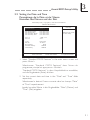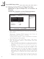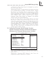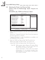
1
PW65 Series Rev. A+ System Board Carte Mère Manuel System-Platine Users Manual Pour Utilisateur Benutzerhandbuch 40220923 Copyright This publication contains information that is protected by copyright. No part of it may be reproduced in any form or by any means or used to make any transformation/ adaptation without the prior written permission from the copyright holders. This publication is provided for informational purposes only. The manufacturer makes no representations or warranties with respect to the contents or use of this manual and specifically disclaims any express or implied warranties of merchantability or fitness for any particular purpose. The user will assume the entire risk of the use or the results of the use of this document. Fur ther, the manufacturer reserves the right to revise this publication and make changes to its contents at any time, without obligation to notify any person or entity of such revisions or changes. © 1999. All Rights Reserved. Trademarks Microsoft® MS-DOS® , WindowsTM, Windows® 95 and Windows ® 98 are registered trademarks of Microsoft Corporation. Intel® , Pentium® II, Pentium ® III and CeleronTM are registered trademarks of Intel Corporation. Award is a registered trademark of Award Software, Inc. Other trademarks and registered trademarks of products appearing in this manual are the properties of their respective holders. Caution: Danger of explosion if battery incorrectly replaced. Replace only with the same or equivalent type recommended by the manufacturer. Dispose of used batteries according to the battery manufacturers instructions. FCC and DOC Statement on Class B This equipment has been tested and found to comply with the limits for a Class B digital device, pursuant to Part 15 of the FCC rules. These limits are designed to provide reasonable protection against harmful interference when the equipment is operated in a residential installation. This equipment generates, uses and can radiate radio frequency energy and, if not installed and used in accordance with the instruction manual, may cause harmful interference to radio communications. However, there is no guarantee that interference will not occur in a particular installation. If this equipment does cause harmful interference to radio or television reception, which can be determined by turning the equipment off and on, the user is encouraged to try to correct the interference by one or more of the following measures: Reorient or relocate the receiving antenna. Increase the separation between the equipment and the receiver. Connect the equipment into an outlet on a circuit different from that to which the receiver is connected. Consult the dealer or an experienced radio TV technician for help. Notice: 1. The changes or modifications not expressly appro ved by the party responsible for compliance could void the user's authority to operate the equipment. 2. Shielded interface cables must be used in order to comply with the emission limits. Table of Contents / Sommaire / Inhaltsverzeichnis Chapter 1 - Introduction 1.1 Features and Specifications.................................................................................. 4 1.2 Package Checklist......................................................................................................... 10 Chapter 2 - Hardware Installation 2.1 2.2 2.3 2.4 2.5 2.6 2.7 2.8 2.9 System Board Layout ............................................................................................. System Memory............................................................................................................. Jumper Settings for Clearing CMOS Data.......................................... Jumper Settings for Wake-On-Keyboard/Mouse.................................... Jumper Settings for the Audio Codec...................................................... Jumper Settings for the Systems Beep Message........................... Jumper Settings for the CPUs Front Side Bus................................ Jumper Settings for the Boot Block Lock/Unlock.......................... Connectors......................................................................................................................... Chapter 3 - Award BIOS Setup Utility 3.1 Entering the Award BIOS Setup Utility.................................................... 3.2 Setting the Date and Time.................................................................................. 3.3 Selecting the Hard Drive and Floppy Drive Type.......................... 3.4 Selecting the Boot Sequence of the Drives........................................ 3.5 Setting the Processor Serial Number Function................................. 3.6 Enabling the AC97 Modem................................................................................ 3.7 Setting the Wake-On-Keyboard/Mouse Function........................... 3.8 Selecting the Power Lost Resume State................................................. 3.9 Selecting the CPU Ratio........................................................................................ 3.10 Using the Suspend to RAM Function....................................................... 3.11 Loading Fail-Safe Defaults/Optimized Defaults................................ 3.12 Setting the Supervisor/User Password.................................................... Chapter 4 - Supported Softwares 4.1 4.2 4.3 4.4 4.5 Hardware Doctor Utility........................................................................................ INF Update Utility for Windows® 95/98............................................. Installing the Graphics Driver............................................................................. Installing the Sound Driver................................................................................... Drivers and Utilities Installation Notes.................................................... 11 13 13 15 16 17 18 19 20 30 31 32 34 35 37 38 42 44 45 50 50 52 52 53 54 54 Appendix A - System Error Messages A.1 POST Beep....................................................................................................................... 55 A.2 Error Messages.............................................................................................................. 55 Note: The users manual in the provided CD contains detailed information about the system board. If, in some cases, some information doesnt match those shown in this manual, this manual should always be regarded as the most updated version. To view the users manual, insert the CD into a CD-ROM drive. The autorun screen (Main Board Utility CD) will appear. Click Users Manual. 1 Introduction Chapter 1 - Introduction / Introduction / Einleitung 1.1 Features and Specifications Caractéristiques et Spécifications Leistungsmerkmale und Technische Daten 1.1.1 Features / Caractéristiques / Leistungsmerkmale Chipset Intel® 810-E (PW65-E) Intel ® 810 DC-100 (PW65-D) Intel® 810 (PW65-S) Intel® 810-L (PW65-L) Processor The system board is equipped with a switching voltage regulator that automatically detects 1.30V to 3.5V. 450/100MHz, 500/100MHz or 550/100MHz Pentium ® III processor 533/133MHz Pentium® III processor (PW65-E) 233/66MHz, 266/66MHz, 300/66MHz, 333/66MHz, 350/100MHz, 400/100MHz or 450/100MHz Pentium® II processor 266/300/300A/333/366/400/433MHz Celeron TM processor (SEPP for Slot 1) System Memory 16MB to 256MB/512MB memory using unbuffered DIMMs with 64MB/128MB technology. (You must use 32MBx64 SDRAM DIMM to support 512MB memory.) Two 168-pin DIMM sockets Uses x64 PC-100 SDRAM DIMM, 3.3V DIMMs 2MBx64 4MBx64 8MBx64 16MBx64 32MBx64 Memory Size 16MB 32MB 64MB 128MB 256MB Expansion Slots The system board is equipped with 5 dedicated PCI slots and 1 AMR slot. AMR (Audio/Modem Riser) is an interface designed for installing an audio riser card, modem riser card or audio/modem riser card that is compliant to the AMR specification. 4 Introduction 1 Onboard Graphics Features Graphics memory - Shares 1MB of the system memory. This is fixed regardless of the size of the system memory. - Uses the Dynamic Display Memory (DDM) technology. This freely changes in size because graphics memory is allocated from the system memory according to current needs. - 4MB onboard display cache (PW65-E and PW65-D only) Graphics controller - 100MHz (PW65-D) or 133MHz (PW65-E) super AGP performance using 4MB display cache memory - 3D hyper pipelined architecture - 2D hardware and motion video acceleration - 9-bit precision hardware motion compensation assistance for software MPEG2 decode - Software DVD at 30fps 2D graphics features - Resolution: up to 1600x1200 in 8-bit color at 85Hz refresh - 64-bit blitter with enhancements - 64x64x3 color transparent cursor - Arithmetic stretch blitter 3D graphics features - 600K-700K tri/sec sustained - 55Mpixels/sec - Flat and Gouraud shading - MIP mapping with bi-linear and anisotropic filtering - 16-bit color/Z-buffering - Discrete/strips/fans - Anisotropic filtering - Texture compositing, color keying and chroma keying Software drivers - Windows® 95/98 - Windows NT® 4.0 Onboard Audio Features Supports Microsoft® DirectSound/DirectSound 3D 32-voice wavetable synthesis 3D positional audio effects AC97 supported with full duplex, independent sample rate converter for audio recording and playback Downloadable sound (DLS) level-1 5 1 Introduction Compatibility Microsoft PC 98 compliant VESA Display Power Management Signaling (DPMS) VESA DDC2B for Plug and Play monitors PCI 2.2, AMR 1.0 and AC 97 compliant ATX Double Deck Ports Two USB ports One NS16C550A-compatible DB-9 serial port One DB-15 VGA port One SPP/ECP/EPP DB-25 parallel port One mini-DIN-6 PS/2 mouse port One mini-DIN-6 PS/2 keyboard port One game/MIDI port Three audio jacks: line-out, line-in and mic-in Connectors One 9-pin connector for external serial port One connector for IrDA interface Two IDE connectors One floppy drive connector supports up to two 2.88MB floppy drives One 20-pin ATX power supply connector One 3-pin Wake-On-LAN connector CPU, chassis and power fan connectors One opened chassis alarm connector Three CD audio-in connectors (2 Sony and 1 Mitsumi) PCI Bus Master IDE Controller Two PCI IDE interfaces support up to four IDE devices Supports Ultra ATA/33 (PW65-L) or ATA/66 (PW65-E, PW65-D or PW65-S) hard drives PIO Mode 4 Enhanced IDE (data transfer rate up to 14MB/sec.) Bus mastering reduces CPU utilization during disk transfer Supports ATAPI CD-ROM, LS-120 and ZIP IrDA Interface The system board is equipped with an IrDA connector for wireless connectivity between your computer and peripheral devices. It supports peripheral devices that meet the IrDA or ASKIR standard. USB Ports The system board is equipped with two USB ports. USB allows data exchange between your computer and a wide range of simultaneously accessible external Plug and Play peripherals. 6 Introduction 1 BIOS Award BIOS, Windows® 95/98 Plug and Play compatible Supports SCSI sequential boot-up Flash EPROM for easy BIOS upgrades (4Mbit) Includes NCR 810 SCSI BIOS Supports DMI 2.0 function Desktop Management Interface (DMI) The system board comes with a DMI 2.0 built into the BIOS. The DMI utility in the BIOS automatically records various information about your system configuration and stores these information in the DMI pool, which is a part of the system board's Plug and Play BIOS. DMI, along with the appropriately networked software, is designed to make inventory, maintenance and troubleshooting of computer systems easier. 1.1.2 System Health Monitor Functions System Health Monitor Fonctions System Health Monitor Funktions The system board is capable of monitoring the following system health conditions. Monitors processor/system/other devices temperature and overheat alarm Monitors 5VSB/VBAT/1.5V/3.3V/±5V/±12V/processor voltages and failure alarm Monitors processor/chassis/power supply fan speed, controls processor/chassis fan speed and failure alarm Automatic fan on/off control Read back capability that displays temperature, voltage and fan speed Opened chassis alarm If you want a warning message to pop-up or a warning alarm to sound when an abnormal condition occurs, you must install the Hardware Doctor utility. This utility is included in the CD that came with the system board. Refer to the Hardware Doctor Utility section in chapter 4 for more information. 1.1.3 Intelligence / Intelligence / Intelligente Ausstattungsteile Automatic CPU/Chassis Fan Off The CPU and chassis fans will automatically turn off once the system enters the Suspend mode. 7 1 Introduction Dual Function Power Button Depending on the setting in the Soft-Off By PWR-BTTN field of the Power Management Setup, this switch will allow the system to enter the Soft-Off or Suspend mode. External Modem Ring-on The Modem Ring-on feature allows the system that is in the Suspend mode or Soft Power Off mode to wake-up/power-on to respond to incoming calls. This feature supports external modem only. RTC Timer to Power-on the System The RTC installed on the system board allows your system to automatically power-on on the set date and time. Wake-On-LAN Ready The Wake-On-LAN function allows the network to remotely wake up a Soft Power Down (Soft-Off) PC. Your LAN card must support the remote wakeup function. Important: The 5VSB power source of your power supply must support ≥720mA (minimum). If you are using the Suspend to RAM function, the 5VSB power source must support a minimum of ≥1.2A. Wake-On-Keyboard/Wake-On-Mouse This function allows you to use the keyboard or mouse to power-on the system. Refer to Jumper Settings for Wake-On-Keyboard/Mouse in chapter 2 and Setting the Wake-On-Keyboard/Mouse Function in chapter 3 for more information. Important: The power button will not function once a keyboard password has been set in the KB Power On Password field of the Integrated Peripherals submenu. You must type the correct password to power-on the system. If you forgot the password, power-off the system and remove the battery. Wait for a few seconds and install it back before powering-on the system. The 5VSB power source of your power supply must support ≥720mA (minimum). If you are using the Suspend to RAM function, the 5VSB power source must support a minimum of ≥1.2A. 8 Introduction 1 AC Power Failure Recovery When power returns after an AC power failure, you may choose to either power-on the system manually, let the system power-on automatically or return to the state where you left off before power failure occurs. Refer to Selecting the Power Lost Resume State in chapter 3 for more information. Year 2000 Compliant Supports hardware Y2K function. Supports hardware Random Number Generator (RNG) to enable a new security and manageability infrastructure for PC. ACPI The system board is designed to meet the ACPI (Advanced Configuration and Power Interface) specification. ACPI has energy saving features that enables PCs to implement Power Management and Plug-and-Play with operating systems that support OS Direct Power Management. Currently, only Windows® 98 suppor ts the ACPI function. ACPI when enabled in the Power Management Setup will allow you to use the Suspend to RAM function. With the Suspend to RAM function enabled, you can power-off the system at once by pressing the power button or selecting Standby when you shut down Windows® 98 without having to go through the sometimes tiresome process of closing files, applications and operating system. This is because the system is capable of storing all programs and data files during the entire operating session into RAM (Random Access Memory) when it powers-off. The operating session will resume exactly where you left off the next time you power-on the system. Refer to Using the Suspend to RAM Function in chapter 3 for more information. Virus Protection Most viruses today destroy data stored in hard drives. The system board is designed to protect the boot sector and partition table of your hard disk drive. 9 1 Introduction 1.2 Package Checklist Liste de Vérification de lEmballage Verpackungsliste The system board package contains the following items: þ þ þ þ þ þ þ ¨ The system board A users manual One card-edge bracket with a serial port One IDE cable for ATA/66 IDE drives (PW65-E, PW65-D or PW65-S) One IDE cable for ATA/33 IDE drives (PW65-L) One 34-pin floppy disk drive cable One Main Board Utility CD One Video Audio Kit CD (optional) If any of these items are missing or damaged, please contact your dealer or sales representative for assistance. 10 Hardware Installation 2 Chapter 2 - Hardware Installation Installation du Matériel Installation der Hardware 2.1 System Board Layout Position de la Carte Système Aufbau der Hauptplatine PW65-E or PW65-D 11 2 Hardware Installation PW65-S or PW65-L Note: The illustrations on the following pages are based on the PW65-S or PW65-L system board, which are boards without SDRAMs. 12 Hardware Installation 2 2.2 System Memory Mémoire Système Systemspeichers The onboard VGA shares 1MB of the system memor y. This is fixed regardless of the size of the system memory. Aside from the 1MB shared memory, it also uses the Dynamic Display Memory (DDM) technology. DDM freely changes in size because graphics memory is allocated from the system memory according to current needs. Refer to chapter 1 for the type of memory suppor ted by the system board. Display Cache (PW65-E and PW65-D only) The PW65-E and PW65-D system boards are each mounted with 2 SDRAMs that serve as 4MB display cache. The presence of the display cache will provide better system performance. 2.3 Jumper Settings for Clearing CMOS Data Positionnement des Cavaliers pour Effacer les Données CMOS Jumpereinstellungen zum Löschen der CMOS Daten Jumper JP2 Clear CMOS Data If you encounter the following, a) CMOS data becomes corrupted; b) You forgot the super visor or user password; c) You are unable to boot-up the computer system because the processors speed/ratio was incorrectly set in the BIOS; you can reconfigure the system with the default values stored in the ROM BIOS. 13 2 Hardware Installation To load the default values stored in the ROM BIOS, please follow the steps below. 1. Power-off the system. 2. Set JP2 pins 2 and 3 to On. Wait for a few seconds and set JP2 back to its default setting, pins 1 and 2 On. 3. Now power-on the system. If your reason for clearing the CMOS data is due to incorrect setting of the processors speed/ratio in the BIOS, please proceed to step 4. 4. After powering-on the system, press <Del> to enter the BIOS setup utility. 5. Select the CPU Frequency Control submenu and press <Enter>. 6. Select the appropriate frequency ratio of the processor in the CPU Ratio field. Refer to Selecting the CPU Ratio in chapter 3 for more information. 7. Press <Esc> to return to the main menu of the BIOS setup utility. Select Save & Exit Setup and press <Enter>. 8. Type <Y> and press <Enter>. 1 2 3 1-2 On: Normal (default) 14 1 2 3 2-3 On: Clear CMOS Data Hardware Installation 2 2.4 Jumper Settings for Wake-On-Keyboard/Mouse Positionnement des Cavaliers pour Réveil-Sur-Clavier/ Souris Jumpereinstellungen für die Wake-On Tastatur/Maus Jumper JP5 Wake-on-Keyboard/Wake-On-Mouse To use the keyboard or mouse to power-on the system, please follow the steps below. 1. Set JP5 to 2-3 On - enable. 2 Keyboard/Mouse Power On in the Integrated Peripherals submenu of the BIOS must be set accordingly. Refer to Setting the Wake-OnKeyboard/Mouse Function in chapter 3 for more information. Warning: 1. If JP5 was previously enabled with a password set in the KB Power On Password field, and now you wish to disable the keyboard password function, make sure to set the Keyboard/Mouse Power On field to Disabled prior to setting JP5 to disabled. You will not be able to boot up the system if you fail to do so. 2. The power button will not function once a keyboard password has been set in the KB Power On Password field of the Integrated Peripherals submenu. You must type the correct password to power-on the system. 3. The 5VSB power source of your power supply must support ≥720mA (minimum). If you are using the Suspend to RAM function, the 5VSB power source must support a minimum of ≥1.2A. 1 2 3 1-2 On: Disable (default) 1 2 3 2-3 On: Enable 15 2 Hardware Installation 2.5 Jumper Settings for the Audio Codec Paramétrage des Cavaliers pour Audio Codec Steckbrückeneinstellungen für den Audio-Codec Jumper JP7 Enable/Disable Audio Codec This jumper is used to enable or disable the audio codec (AC97) on the system board. By default, the onboard audio codec is enabled. If you are using the AMR cards audio codec, set pins 1 and 2 to On. Please refer to the table below on how the jumper and the BIOS should be configured in different situations or system configurations. 1 2 3 1 1-2 On: Disable 2 3 2-3 On: Enable (default) Nomenclature BIOS - AC97 Audio : Refers to the AC97 Audio field in the Integrated Peripherals submenu. BIOS - AC97 Modem : Refers to the AC97 Modem field in the Integrated Peripherals submenu. 16 1. Onboard audio (primary) + No card in AMR or PCI/ISA slot 2. Primary audio riser in AMR slot = JP7: disable BIOS - AC97 Audio: enable 3. Onboard audio (primary) + Secondary audio riser in AMR slot 4. Onboard audio (primary) + Secondary modem riser in AMR slot enable = JP7: BIOS - AC97 Audio: enable BIOS - AC97 Modem: enable 5. Onboard audio (primary) + PCI modem card in PCI slot enable = JP7: BIOS - AC97 Audio: enable BIOS - AC97 Modem: disable = JP7: enable BIOS - AC97 Audio: enable = JP7: enable BIOS - AC97 Audio: enable Hardware Installation 6. PCI sound card in PCI slot = 7. PCI sound card in PCI slot + Primary modem riser in AMR slot = JP7: disable BIOS - AC97 Audio: disable BIOS - AC97 Modem: enable 8. PCI sound card in PCI slot + Secondary modem riser in AMR slot = JP7: enable BIOS - AC97 Audio: disable BIOS - AC97 Modem: enable 9. PCI sound card in PCI slot + PCI modem card in PCI slot no effect; ignore = JP7: BIOS - AC97 Audio: disable BIOS - AC97 Modem: disable 10. Audio Modem riser in AMR slot = 2 JP7: no effect; ignore BIOS - AC97 Audio: disable JP7: disable BIOS - AC97 Audio: enable BIOS - AC97 Modem: enable 2.6 Jumper Settings for the Systems Beep Message Paramétrage des Cavaliers pour le Message de Bip du Système Steckbrückeneinstellungen für die akustische Meldung des Systems Jumper JP8 Systems Beep Message Output Select This jumper is used to select the speaker from which the systems beep message will sound. If you want the systems beep message to come from the external speaker that is connected to the line-out jack, set this jumper pins 1 and 2 to On. If you want the systems beep message to come from the PCs speaker, set this jumper pins 2 and 3 to On. 1 2 3 1-2 On: External speaker 1 2 3 2-3 On: PCs speaker (default) 17 2 Hardware Installation 2.7 Jumper Settings for the CPUs Front Side Bus Positionnement des Cavaliers pour le Bus Frontal du Processeur Jumpereinstellungen fuer CPU Vorderseitenbus Jumper JP9 CPUs Front Side Bus Select The default setting of jumper JP9 is Auto - the system will automatically run according to the FSB of the processor. If you wish to overclock a 66MHz FSB processor to 100MHz, set pins 1, 2 and 3 to Off. If you want a 100MHz FSB processor to run at 66MHz, set pins 1 and 2 to On. Warning: Overclocking a 66MHz FSB processor to 100MHz will provide better system performance. However, not all 66MHz FSB processors are capable of running at 100MHz bus speed. Therefore, if you are unable to boot your system when set at 100MHz, make sure to set JP9 back to its default setting. 1 1 1 2 2 2 3 3 3 1-2 On: 66MHz 18 2-3 On: Auto (default) 1-2-3 Off: 100MHz Hardware Installation 2 2.8 Jumper Settings for the Boot Block Lock/Unlock Paramétrage des Cavaliers pour le Verrouillage/ Déverrouillage du Bloc dInitialisation Steckbrückeneinstellungen für die Blockierung/ Entriegelung des Ladeblocks Jumper JP6 Boot Block Lock/Unlock This jumper is for factor y use only. Please leave it in its default setting. 1 1 2 2 3 3 1-2 On: Unlock boot block (default) 2-3 On: Lock Boot Block 19 2 Hardware Installation 2.9 Connectors / Connecteurs / Anschlüsse 2.9.1 Serial Ports / Parallel Port Ports Série / Port Parallèle Serielle Anschlüsse / Paralleler Anschluß 2.9.2 PS/2 Mouse Port / PS/2 Keyboard Port Ports Souris PS/2 / Ports Clavier PS/2 PS/2-Maus-Anschluß / PS/2-Tastatur-Anschluß Warning: Make sure to turn off your computer prior to connecting or disconnecting a mouse or keyboard. Failure to do so may damage the system board. 20 Hardware Installation 2 2.9.3 Floppy Disk Drive Controller and IDE Interface Contrôleur de Lecteur de Disquette et Interface IDE Diskettenlaufwerkcontroller und IDE Interface Important: If you encountered problems while using an ATAPI CD-ROM drive that is set in Master mode, please set the CD-ROM drive to Slave mode. Some ATAPI CD-ROMs may not be recognized and cannot be used if incorrectly set in Master mode. 2.9.4 Universal Serial Bus Ports Ports de Bus Série Universels Universelle Serielle Bus-Anschlüsse 21 2 Hardware Installation 2.9.5 IrDA Connector Connecteur IrDA IrDA Anschlüsse Pin Function 1 IRTX 2 Ground 3 IRRX 4 N. C. 5 VCC 2.9.6 CPU Fan Connector Connecteur du Ventilateur de CPU CPU Kühlung Anschluß 22 Pin Function 1 Ground 2 On/Off 3 Sense Hardware Installation 2 2.9.7 Chassis Fan Connector Connecteur de Châssis de Ventilateur Anschluß Kühlungsgehäuse Pin Function 1 Ground 2 On/Off 3 Sense 2.9.8 Power Fan Connector Connecteur du Ventilateur dAlimentation Anschluß für den Ventilator des Netzteils Pin Function 1 Ground 2 +12V 3 Sense 23 2 Hardware Installation 2.9.9 Wake-On-LAN Connector Connecteur Réveil-Sur-LAN Wake-On-LAN Anschluß Pin Function 1 WOL 2 Ground 3 +5VSB (720mA) Important: The 5VSB power source of your power supply must support ≥720mA (minimum). If you are using the Suspend to RAM function, the 5VSB power source must support a minimum of ≥1.2A. 2.9.10 Thermal Connector Connecteur Thermique Thermovebinder 24 Pin Function 1 Ground 2 Sensor Hardware Installation 2 2.9.11 VGA Port Port VGA VGA-Anschluß 2.9.12 Game/MIDI Port / Audio Jacks Port Jeu/MIDI / Prises Audio Game-/MIDI-Anschluß / Audio-Anschlußbuchsen 25 2 Hardware Installation 2.9.13 CD Audio-in Connector Connecteurs dentrée Audio CD CD-Audio-In-Anschlußstecker J12 Sony J10 - Sony J11 - Mitsumi Pin J12 - Sony J10 - Sony J11 - Mitsumi 1 CD-R CD-R CD-R 2 CD-G CD-G CD-G 3 CD-G CD-G CD-L 4 CD-L CD-L CD-G 2.9.14 Chassis Open Connector Connecteur de Châssis Ouvert Chassisöffnungsanschluß Pin 26 Function 1 Ground 2 Chassis signal 3 N. C. 4 +5V Hardware Installation 2 2.9.15 Power Connector Connecteur dAlimentation Netzanschluß Pin Function Pin Function 1 3.3V/14A 11 3.3V/14A 2 3.3V/14A 12 -12V 3 Ground 13 Ground 4 +5V 14 PS-ON 5 Ground 15 Ground 6 +5V 16 Ground 7 Ground 17 Ground 8 PW-OK 18 -5V 9 5VSB 19 +5V 10 +12V 20 +5V Important: Your power supply must meet the ATX specification - supporting 3.3V/14A (minimum), otherwise your system will not boot properly. 27 2 Hardware Installation 2.9.16 DIMM/PCI Standby Power LED LED dAlimentation de veille DIMM/PCI DIMM/PCI-Standby-Betriebsanzeige-LED DIMM Standby Power LED This LED will light when the system is in the power-on or Suspend mode. It will not light when the system is in the Soft-Off state. PCI Standby Power LED This LED will light when the system is in the power-on, SoftOff or Suspend mode. Lighted LEDs ser ve as a reminder that you must power-off the system then turn off the power supplys switch or unplug the power cord prior to installing any DIM modules or add-on cards. 2.9.17 LEDs and Switches Commutateurs et LED LEDs und Schalter 28 Hardware Installation HD-LED (Primary/Secondary IDE LED) G-LED (Green LED) ATX-SW (ATX power switch) G-SW (Green switch) RESET (Reset switch) SPEAKER (Speaker connector) KEYLOCK (Power/Standby LED and Keylock connector) Pin 1 2 3 4 5 6 7 8 9 10 11 12 13 14 15 16 17 18 19 20 21 22 23 24 25 2 Pin Assignment HDD LED Power HDD N. C. Green LED Power Green N. C. PWRBT Ground N. C. SMI Ground N. C. H/W Reset Ground N. C. Speaker Data N. C. Ground Speaker Power N. C. LED Power N.C. Standby Signal Keylock Ground Use pins 21-23 for the Power/Standby LED. Note: 1. ATX-SW (ATX Power Switch) - Depending on the setting in the Soft-Off By PWR-BTTN field in the Power Management Setup, this switch is a dual function power button that will allow your system to enter the Soft-Off or Suspend mode. 2. When the system is in the S1 (POS - Power On Suspend) state, the Green LED and Power/Standby LED will blink every second. 3. When the system is in the S3 (STR - Suspend To RAM) state, the Power/Standby LED will blink every 4 seconds. 29 3 Award BIOS Setup Utility Chapter 3 - Award BIOS Setup Utility Utilitaire de Configuration du Award BIOS AWARD BIOS Konfigurationsprogramm 3.1 Entering the Award BIOS Setup Utility Entrer Dans lUtilitaire de Configuration du Award BIOS Aufruf des AWARD BIOS Konfigurationsprogramms Power-on the system and press <Del> to enter the utility. The main menu screen will appear. Allumez le Système et appuyez sur <Del> pour entrer dans lutilitaire. Lécran du programme principal apparaîtra. Zum Aufrufen des Konfigurationsprogramms drücken Sie während des Startvorgangs die Taste <Del>. Ein Bildschirm ähnlich dem folgenden erscheint. CMOS Setup Utility - Copyright (C) 1984-1999 Award Software Standard CMOS Features CPU Frequency Control Advanced BIOS Features Load Fail-Safe Defaults Advanced Chipset Features Load Optimized Defaults Integrated Peripherals Set Supervisor Password Power Management Setup Set User Password PnP/PCI Configurations Save & Exit Setup System Health Monitor Exit Without Saving Esc F10 : Quit : Save & Exit Setup ↑↓→← Time, Date, Hard Disk Type... 30 : Select Item Award BIOS Setup Utility 3 3.2 Setting the Date and Time Paramétrage de la Date et de lHeure Einstellen des Datums und der Zeit CMOS Setup Utility - Copyright (C) 1984-1999 Award Software Standard CMOS Features Date (mm:dd:yy) Time (hh:mm:ss) Sat, Jan 2 1999 4 : 35 : 5 IDE IDE IDE IDE Press Press Press Press Primary Master Primary Slave Secondary Master Secondary Slave Enter Enter Enter Enter None None None None Drive A Drive B 1.44M, 3.5 in. None Video Halt On EGA/VGA All Errors Base Memory Extended Memory Total Memory Item Help Menu Level Change the day, month, year and century 640K 129024K 130048K ↑↓→← Move Enter:Select +/-/PU/PD:Value F10:Save F5:Previous Values F6:Fail-Safe Defaults ESC:Exit F1:General Help F7:Optimized Defaults 1. Select Standard CMOS Features in the main menu screen and press <Enter>. Sélectionnez Standard CMOS Features dans lécran du programme principal et appuyez sur <Entrée>. Standard CMOS Features in dem Hauptbildschirm auswählen, und die Eingabetaste (Enter) drücken. 2. Set the correct date and time in the Date and Time fields respectively. Sélectionnez la date et lheure correcte dans les champs Date et Time respectivement. Jeweils korrekte Wer te in die Eingabefelder Date (Datum) und Time (Zeit) eingeben. 31 3 Award BIOS Setup Utility 3.3 Selecting the Hard Drive and Floppy Drive Type Sélectionnez le Type de Disque Dur et de Lecteur de Disquette Auswahl der Festplatte und des Diskettenlaufwerks CMOS Setup Utility - Copyright (C) 1984-1999 Award Software Standard CMOS Features Date (mm:dd:yy) Time (hh:mm:ss) Sat, Jan 2 1999 4 : 35 : 5 IDE IDE IDE IDE Press Press Press Press Primary Master Primary Slave Secondary Master Secondary Slave Enter Enter Enter Enter None None None None Drive A Drive B 1.44M, 3.5 in. None Video Halt On EGA/VGA All Errors Base Memory Extended Memory Total Memory Item Help Menu Level To enter next page for detail hard drive settings. 640K 129024K 130048K ↑↓→← Move Enter:Select +/-/PU/PD:Value F10:Save F5:Previous Values F6:Fail-Safe Defaults ESC:Exit F1:General Help F7:Optimized Defaults 1. Select Standard CMOS Features in the main menu screen and press <Enter>. Sélectionnez Standard CMOS Features dans lécran du programme principal et appuyez sur <Entrée>. Standard CMOS Features in dem Hauptbildschirm auswählen, und die Eingabetaste (Enter) drücken. 2. Move the cursor to the IDE Primar y Master, IDE Primar y Slave, IDE Secondar y Master or IDE Secondary Slave field, then press <Enter>. Select IDE HDD Auto Detection to detect the parameters of the drive. These parameters will automatically be shown on the screen. If you wish to define your own drive type manually, select Manual. This information should be included in the documentation from your hard disk vendor. If you select Auto, the BIOS will auto-detect the HDD & CD-ROM drive at the POST stage and show the IDE for the HDD & CD-ROM drive. If a hard disk has not been installed, select None. Move to the Access Mode field. For hard drives larger than 528MB, you would typically select the LBA type. Cer tain 32 Award BIOS Setup Utility 3 operating systems require that you select Normal or Large. Please check your operating systems manual or Help desk on which one to select. Déplacez le curseur sur le champ de IDE Primar y Master, IDE Primary Slave, IDE Secondary Master ou IDE Secondary Slave, puis appuyez sur <Entrée>. Sélectionnez IDE HDD Auto Detection pour détecter les par amètres du disque dur. Ces par amètres seront automatiquement affichés à lécran. Si vous désirez définir votre propre lecteur manuellement, sélectionnez Manual. Ces informations devraient être inclues dans la documentation provenant du fabricant de votre disque dur. Si vous sélectionnez Auto, le BIOS détectera automatiquement le Disque Dur & le lecteur CD-ROM durant la phase du POST et affichera le IDE pour le Disque Dur & et le lecteur CD-ROM. Si aucun disque dur na été installé, sélectionnez None. Déplacez vous sur le champ Access Mode. Pour les disques durs dune capacité supérieure à 528 Mo, vous sélectionnerez dune façon générale le type LBA. Cer tains systèmes dexploitation nécessitent que vous sélectionniez Normal ou Large. Veuillez vous reporter au manuel de votre système dexploitation ou à lAide en ce qui concerne celui que vous devez sélectionner. Den Cursor auf das Feld IDE Primar y Master, IDE Primary Slave, IDE Secondar y Master oder IDE Secondar y Slave bewegen und dann die Eingabetaste (Enter) drücken. Wählen Sie IDE HDD Auto Detection aus, um die Parameter des Laufwer ks zu entdecken. Diese Parameter erscheinen automatisch auf dem Schirm. Falls Sie Ihren Laufwerktyp selbst bestimmen möchten, wählen Sie Manual aus. Diese Informationen müssen im Handbuch von Ihrem Festplattenverkäufer vorhanden sein. Wählen Sie Auto aus, wird das Festplatten- und das CD-ROMLaufwerk durch das BIOS automatisch entdeckt und der IDE für das Festplatten- und CD-ROM-Laufwerk wird angezeigt. Falls keine Festplatte installiert wurde, wählen Sie None aus. Den Cur sor auf das Feld Access Mode bewegen. Für Festplattenlaufwerke mit einer Kapazität von mehr als 52MB wird typischerweise der LBA-Typ ausgewählt. Für bestimmte Betriebssysteme muß Normal oder Large ausgewählt werden. Angaben zur richtigen Auswahl sind im Handbuch des Betriebssystems oder im Hilfe-Desk enthalten. 33 3 Award BIOS Setup Utility 3. Set the type of floppy drive installed in the Drive A and Drive B fields. The options are None, 360K, 1.2M, 720K, 1.44M and 2.88M. Paramétrez le type de lecteur de disquette installé dans les champs Drive A et Drive B. Les options sont None, 360K, 1.2M, 720K, 1.44M et 2.88M. Im Eintrag Floppy Drive (Diskettenlaufwerk) wählen Sie Drive A (Laufwerk A) und Drive B (Laufwerk B). Die Optionen sind None (Kein), 360K, 1.2M, 720K, 1.44M und 2.88M. 3.4 Selecting the Boot Sequence of the Drives Sélection de la Séquence dAmorçage des Lecteurs Bestimmen der Startreihenfolge der Laufwerke CMOS Setup Utility - Copyright (C) 1984-1999 Award Software Advanced BIOS Features Virus Warning CPU L1 Cache CPU L2 Cache CPU L2 Cache ECC Checking Processor Serial Number Quick Power On Self Test First Boot Device Second Boot Device Third Boot Device Boot Other Device Swap Floppy Drive Boot Up Floppy Seek Boot Up NumLock Status Typematic Rate Setting Typematic Rate (Chars/Sec) Typematic Delay (Msec) Security Option OS Select For DRAM > 64MB HDD S.M.A.R.T. Capability Disabled Enabled Enabled Enabled Disabled Enabled Floppy HDD-0 LS/ZIP Enabled Disabled Disabled Off Disabled 6 250 Setup Non-OS2 Disabled ↑↓→← Move Enter:Select +/-/PU/PD:Value F10:Save F5:Previous Values F6:Fail-Safe Defaults Item Help Menu Level Select your boot device priority. ESC:Exit F1:General Help F7:Optimized Defaults 1. Select Advanced BIOS Features in the main menu screen and press <Enter>. Sélectionnez Advanced BIOS Features dans lécran de programme principal et appuyez sur <Entrée>. Advanced BIOS Features in dem Hauptbildschirm auswählen, und die Eingabetaste (Enter) drücken. 2. Select the drive to boot first, second and third in the First Boot Device Second Boot Device and Third Boot Device fields respectively. The BIOS will boot the operating system according to the sequence of the drive selected. The options are: Floppy, LS/ZIP, HDD-0, SCSI, CDROM, HDD-1, HDD-2, HDD-3, LAN 34 Award BIOS Setup Utility 3 and Disable. Set Boot Other Device to Enabled if you wish to boot from another device. Sélectionnez le lecteur sur lequel amorcer en premier, en second et en troisième dans les champs First Boot Device Second Boot Device et Third Boot Device respectivement. Le BIOS amorcera le système dexploitation en fonction de la séquence de lecteur sélectionnée. Les options sont: Floppy, LS/ZIP, HDD-0, SCSI, CDROM, HDD-1, HDD-2, HDD-3, LAN et Disable. Positionnez Boot Other Device sur Enabled si vous désirez amorcer à partir dun autre périphérique. Im Feld First Boot Device Second Boot Device und Third Boot Device wählen Sie jeweils das Gerät aus, das als erstes, zweites bzw. drittes geladen werden soll. Das Betriebssystem wird durch das BIOS gemäß der Reihenfolge des ausgewählten Laufwerks geladen. Die Optionen sind: Floppy, LS/ZIP, HDD-0, SCSI, CDROM, HDD-1, HDD-2, HDD-3, LAN und Disable. Stellen Sie Boot Other Device auf Enabled, falls Sie von einem anderen Gerät aus laden möchten. 3.5 Setting the Processor Serial Number Function Activer la Fonction Numéro de Série de Processeur Aktivieren der Prozessor-Seriennummer Funktion CMOS Setup Utility - Copyright (C) 1984-1999 Award Software Advanced BIOS Features Virus Warning CPU L1 Cache CPU L2 Cache CPU L2 Cache ECC Checking Processor Serial Number Quick Power On Self Test First Boot Device Second Boot Device Third Boot Device Boot Other Device Swap Floppy Drive Boot Up Floppy Seek Boot Up NumLock Status Typematic Rate Setting Typematic Rate (Chars/Sec) Typematic Delay (Msec) Security Option OS Select For DRAM > 64MB HDD S.M.A.R.T. Capability Disabled Enabled Enabled Enabled Disabled Enabled Floppy HDD-0 LS/ZIP Enabled Disabled Disabled Off Disabled 6 250 Setup Non-OS2 Disabled ↑↓→← Move Enter:Select +/-/PU/PD:Value F10:Save F5:Previous Values F6:Fail-Safe Defaults Item Help Menu Level ESC:Exit F1:General Help F7:Optimized Defaults 1. Select Advanced BIOS Features in the main menu screen and press <Enter>. Sélectionnez Advanced BIOS Features dans lécran de programme principal et appuyez sur <Entrée>. 35 3 Award BIOS Setup Utility Advanced BIOS Features in dem Hauptbildschirm auswählen, und die Eingabetaste (Enter) drücken. 2. Select Processor Serial Number. The options are Disabled and Enabled. This field will appear only when you are using a Pentium III processor. Each Pentium III processor comes with an individual "processor serial number" which by default is activated. Therefore, when connected to the Internet, Pentium III processor transmits the serial number online making it possible to track your online activity. This field provides you the option of disabling this function. Sélectionnez Processor Serial Number. Les options sont Disabled et Enabled. Ce champ apparaît seulement lorsque vous utilisez un Processeur Pentium III. Chaque processeur Pentium III est livré avec un Numéro de Série de Processeur Individuel qui est activé par défaut. De ce fait, lorsque vous êtes connecté sur Internet, le processeur Pentium III transmet le numéro de série en ligne rendant possible le dépistage de votre activité en ligne. Dans ce champs vous trouverez loption pour la désactivation de cette fonction. Im Processor Serial Number Feld sind folgende Optionen möglich Disabled und Enabled. Dieses Feld erscheint nur, wenn Sie mit einem Pentium III Prozessor arbeiten. Jeder Pentium III Prozessor besitzt eine eigene Prozessor-Seriennummer, die automatisch aktivier t wird. Daher wird die Seriennummer durch den Pentium III Prozessor online über tragen, wenn Sie im Internet verbunden sind, damit Sie immer einen Überblick über Ihre Online-Aktivität haben. Mit der Option im Feld kann diese Funktion deaktiviert werden. 36 Award BIOS Setup Utility 3 3.6 Enabling the AC97 Modem Activation du Modem AC97 Das AC97-Modem aktivieren CMOS Setup Utility - Copyright (C) 1984-1999 Award Software Integrated Peripherals On-Chip Primary PCI IDE On-Chip Secondary PCI IDE IDE Primary Master PIO IDE Primary Slave PIO IDE Secondary Master PIO IDE Secondary Slave PIO IDE Primary Master UDMA IDE Primary Slave UDMA IDE Secondary Master UDMA IDE Secondary Slave UDMA USB Controller USB Keyboard Support Init Display First AC97 Audio AC97 Modem IDE HDD Block Mode Keyboard/Mouse Power On X KB Power On Password X KB Power On Hot Key Enabled Enabled Auto Auto Auto Auto Auto Auto Auto Auto Enabled Disabled PCI Slot Enabled Disabled Enabled Disabled Enter Ctrl-F1 ↑↓→← Move Enter:Select +/-/PU/PD:Value F10:Save F5:Previous Values F6:Fail-Safe Defaults Item Help Menu Level ESC:Exit F1:General Help F7:Optimized Defaults 1. Select Integrated Peripherals in the main menu screen and press <Enter>. Sélectionnez Integrated Peripherals dans lécran de programme principal et appuyez sur <Entrée>. Integrated Peripherals in dem Hauptbildschirm auswählen, und die Eingabetaste (Enter) drücken. 2. If you have installed a modem riser or audio/modem riser card in the AMR slot, you must set the AC97 Modem field to Enabled. Si vous avez installé un élévateur de modem ou un élévateur de car te audio/modem dans le logement AMR, vous devez positionner le champ AC97 Modem sur Enabled. Falls eine Modem-Riser- oder eine Audio/Modem-Riser-Karte in der AMR-Steckfassung installier t wurde, muß im Feld AC97 Modem Enabled ausgewählt werden. 37 3 Award BIOS Setup Utility 3.7 Setting the Wake-On-Keyboard/Mouse Function Activer la Fonction Réveil-Sur-Clavier/Souris Aktivieren der Wake-On Tastatur/Maus Funktion CMOS Setup Utility - Copyright (C) 1984-1999 Award Software Integrated Peripherals On-Chip Primary PCI IDE On-Chip Secondary PCI IDE IDE Primary Master PIO IDE Primary Slave PIO IDE Secondary Master PIO IDE Secondary Slave PIO IDE Primary Master UDMA IDE Primary Slave UDMA IDE Secondary Master UDMA IDE Secondary Slave UDMA USB Controller USB Keyboard Support Init Display First AC97 Audio AC97 Modem IDE HDD Block Mode Keyboard/Mouse Power On X KB Power On Password X KB Power On Hot Key Enabled Enabled Auto Auto Auto Auto Auto Auto Auto Auto Enabled Disabled PCI Slot Enabled Disabled Enabled Disabled Enter Ctrl-F1 ↑↓→← Move Enter:Select +/-/PU/PD:Value F10:Save F5:Previous Values F6:Fail-Safe Defaults Item Help Menu Level ESC:Exit F1:General Help F7:Optimized Defaults 1. Select Integrated Peripherals in the main menu screen and press <Enter>. Sélectionnez Integrated Peripherals dans lécran de programme principal et appuyez sur <Entrée>. Integrated Peripherals in dem Hauptbildschirm auswählen, und die Eingabetaste (Enter) drücken. 2. Select Keyboard/Mouse Power On. The options are: Sélectionnez Keyboard/Mouse Power On. Les options sont: Im Keyboard/Mouse Power On Feld sind folgende Optionen möglich: Disabled Default setting / Valeur par défaut / Voreinstellung. Warning / Attention / Warnung: If JP5 was previously enabled with a password set in the KB Power On Password field, and now you wish to disable the keyboard password function, make sure to set this field to disabled prior to setting JP5 to disabled (1-2 On). You will not be able to boot up the system if you fail to do so. 38 Award BIOS Setup Utility 3 Si JP5 a été activé précédemment avec un mot de passe paramétré dans le KB Power On Password, et que vous désir iez maintenant désactiver la fonction de Réveil par Clavier (mot de passe), assurez-vous de positionner le champ sur désactivé avant de positionner JP5 sur désactivé (1-2 Sélectionné). Si vous ne procédez pas ainsi, vous ne pourrez pas amorcer le système. Falls JP5 zuvor mit einem Kennwort im Feld KB Power On Password aktiviert worden ist und Sie nun die Funktion Wake-On-Keyboard (Kennwort) deaktivieren wollen, muß dieses Feld auf Deaktiviert eingestellt werden, bevor JP5 auf Deaktiviert (1-2 Ein) eingestellt wird, da sonst das System nicht gestartet werden kann. Password When this option is selected, move the cursor to the KB Power On Password field and press <Enter>. Enter your password. You can enter up to 5 characters. Type in exactly the same password to confirm, then press <Enter>. Quand cette option est sélectionnée, la rubrique KB Power On Password apparaîtra. Déplacez votre curseur dans cette rubrique et appuyez sur Entrée. Entrez votre mot de passe. Vous pouvez entrer jusquà 5 caractères. Tapez exactement le même mot de passe pour confirmer et appuyez sur Entrée. Wenn diese Option gewaehlt wird, wird das KB Power On Password -Feld erscheinen. Bewegen Sie den Cursor auf dieses Feld und dr uecken Sie <Enter>. Geben Sie Ihr Passwort ein. Sie koennen bis zu 5 Zeichen eingeben. Tippen Sie nocheinmal genau dasselbe Passwor t ein, um dieses zu bestaetigen und druecken Sie dann <Enter>. Important / Important / Wichtig: The power button will not function once a keyboard password has been set in the KB Power On Password field. You must type the correct password to power-on the system. If you forgot the password, power-off the system 39 3 Award BIOS Setup Utility and remove the batter y. Wait for a few seconds and install it back before powering-on the system. Le bouton de mise sous tension ne fonctionnera plus une fois quun mot de passe aura été entré dans le champ KB Power On Password. Vous devez taper le mot de passe correct pour allumer votre système. Si vous oubliez votre mot de passe, éteignez le système et retirez la batterie. Attendez quelques secondes et réinstallez-la avant de rallumer le système. Nach dem Einstellen eines Tastatur-Kennwortes im Feld KB Power On Password wird die Netztaste nicht funktionieren. Zum Einschalten des Systems muß das richtige Kennwort eingegeben werden. Falls Sie das Kennwort vergessen haben, schalten Sie das System aus. Dann die Batterie entfernen. Warten Sie einige Sekunden und installieren Sie danach die Batterie wieder, bevor Sie das System erneut einschalten. Hot Key When this option is selected, move the cursor to the KB Power On Hot Key field to select a function key you would like to use to power-on the system. The options are from Ctrl-F1 to Ctrl-F12. Quand cette option est choisie, la rubrique KB Power On Hot Key apparaîtra. Déplacez le curseur dans cette rubrique pour sélectionner la touche de fonction que vous souhaitez utiliser pour allumer le système. Les options vont de Ctrl-F1 à Ctrl-F12. Wenn diese Option gewaehlt wird, wird das Feld fuer die KB Power On Hot Key fuer den Star t des Computers erscheinen. Bewegen Sie die Maus auf dieses Feld um eine Tastenkombination zu waehlen, mit der Sie das System star ten moechten. Die Optionen sind Ctrl-F1 bis Ctrl-F12. Mouse Left 40 When this option is selected, double-click the left button of the mouse to power-on the system. Award BIOS Setup Utility 3 Quand cette option est choisie, double-cliquez sur le bouton gauche de la souris pour allumer le système. Wenn diese Option gewaehlt wird, druecken Sie zweimal die linke Maustaste, um das System zu starten. Mouse Right When this option is selected, double-click the right button of the mouse to power-on the system. Quand cette option est choisie, double-cliquez sur le bouton droit de la souris pour allumer le système. Wenn diese Option gewaehlt wird, druecken Sie zweimal die rechte Maustaste, um das System zu starten. Any Key You can press any key to power-on the system. Vous pouvez appuyez sur nimporte quelle touche pour allumer le système. Sie koennen jede Taste druecken, um das System zu starten. Keyboard 98 When this option is selected, press the wake up key of the Windows 98 compatible keyboard to power-on the system. Quand cette option est sélectionnée, appuyez sur la touche Réveil du clavier compatible Windows 98 pour activer le système. Wenn diese Option gewählt wurde, drücken Sie die Aufweck-Taste der mit dem Windows ® 98 kompatiblen Tastatur, um das System einzuschalten. Important / Important / Wichtig: Make sure JP5 is set to 2-3 On. Refer to Jumper Settings for Wake-On-Keyboard/Wake-On-Mouse in chapter 2 of this manual for more information. Assurez vous que JP5 est positionné sur la sélection 2-3. Pour plus de renseignements, reportez-vous à Positionnement des Cavaliers pour Réveil-Sur-Clavier/Souris au chapitre de ce manuel. Es ist darauf zu achten, daß sich JP5 in der Einstellung 2-3 An befindet. Schauen Sie unter Jumpereinstellungen für die WakeOn-Tastatur/Maus in Kapitel 2 dieses Handbuches nach, um weitere Information zu erhalten. 41 3 Award BIOS Setup Utility 3.8 Selecting the Power Lost Resume State Choisir létat de Redémarrage Après Coupure de Courant Auswaehlen des PWR Lost Resume Status CMOS Setup Utility - Copyright (C) 1984-1999 Award Software Integrated Peripherals AC97 Modem IDE HDD Block Mode Keyboard/Mouse Power On KB Power On Password KB Power On Hot Key Onboard FDC Controller Onboard Serial Port 1 Onboard Serial Port 2 UART2 Mode Select X RxD, TxD Active X IR Transmission Delay Onboard Parallel Port Parallel Port Mode EPP Mode Select ECP Mode Use DMA PWR Lost Resume State Game Port Address Midi Port Address X Midi Port IRQ Disabled Enabled Disabled Enter Ctrl-F1 Enabled 3F8/IRQ4 2F8/IRQ3 Normal Hi,Lo Enabled 378/IRQ7 ECP+EPP EPP1.7 3 Keep Off 201 Disabled 5 ↑↓→← Move Enter:Select +/-/PU/PD:Value F10:Save F5:Previous Values F6:Fail-Safe Defaults Item Help Menu Level ESC:Exit F1:General Help F7:Optimized Defaults 1. Select Integrated Peripherals in the main menu screen and press <Enter>. Sélectionnez Integrated Peripherals dans lécran de programme principal et appuyez sur <Entrée>. Integrated Peripherals in dem Hauptbildschirm auswählen, und die Eingabetaste (Enter) drücken. 2. Select the PWR Lost Resume State field. The options are: Sélectionnez PWR Lost Resume State. Les options sont In dem Feld PWR Lost Resume State. Die Optionen sind: Keep Off When power returns after an AC power failure, the systems power is off. You must press the Power button to power-on the system. Quand lalimentation revient après une coupure dalimentation C A, le système est éteint. Vous devez appuyer sur linterrupteur dAlimentation pour allumer le système. 42 Award BIOS Setup Utility 3 Beim Wiederherstellen der Stromversorgung nach einem Wechselstromausfall wird der Betrieb des Systems ausgeschaltet. Drücken Sie auf die Netztaste, um das System einzuschalten. Turn On When power returns after an AC power failure, the system will automatically power-on. Quand lalimentation revient après une coupure dalimentation C A, le système sallumer a automatiquement. Beim Wiederherstellen der Stromversorgung nach einem Wechselstromausfall wird das System automatisch eingeschaltet. Last State When power returns after an AC power failure, the system will return to the state where you left off before power failure occurs. If the systems power is off when AC power failure occurs, it will remain off when power returns. If the systems power is on when AC power failure occurs, the system will power-on when power returns. Quand lalimentation revient après une coupure dalimentation CA, le système retournera à létat où vous lavez laissé avant la coupure dalimentation. Si le système est éteint quand la coupure dalimentation CA se produit, il restera éteint lorsque le courant sera rétabli. Si le système est allumé quand la coupure dalimentation se produit, le système sallumera lorsque le courant sera rétabli. Beim Wiederherstellen der Stromversorgung nach einem Wechselstromausfall kehr t das System in den Status zurück, in welchem es sich beim Auftreten des Stromausfalles befand. Falls das System beim Auftreten des Stromausfalles ausgeschaltet war, wird das System beim Wiederher stellen der Stromver sorgung nicht eingeschaltet. Falls die Stromver sor gung des Systems beim Auftreten des Wechselstromausfalles eingeschaltet war, wird es beim Wiederherstellen der Stromversorgung eingeschaltet. 43 3 Award BIOS Setup Utility 3.9 Selecting the CPU Ratio Sélection du Rapport de CPU Das CPU-Verhältnis auswählen CMOS Setup Utility - Copyright (C) 1984-1999 Award Software CPU Frequency Control CPU Clock/Spread Spectrum CPU Ratio Default X3 ↑↓→← Move Enter:Select +/-/PU/PD:Value F10:Save F5:Previous Values F6:Fail-Safe Defaults Item Help Menu Level ESC:Exit F1:General Help F7:Optimized Defaults 1. Select CPU Frequency Control in the main menu screen and press <Enter>. Sélectionnez CPU Frequency Control dans lécran de programme principal et appuyez sur <Entrée>. CPU Frequency Control in dem Hauptbildschirm auswählen, und die Eingabetaste (Enter) drücken. 2. Select the CPU Ratio field. The options are: X 3, X 3.5, X 4, X 4.5, X 5, X 5.5, X 6, X 6.5, X 7 and X 7.5. Sélectionnez CPU Ratio. Les options sont X 3, X 3.5, X 4, X 4.5, X 5, X 5.5, X 6, X 6.5, X 7 et X 7.5. In dem Feld CPU Ratio. Die Optionen sind: X 3, X 3.5, X 4, X 4.5, X 5, X 5.5, X 6, X 6.5, X 7 und X 7.5. Important / Important / Wichtig: The frequency ratio of some processors has been fixed by the manufacturer, therefore you will not be able to overclock them. If you are using this kind of processor, please ignore this section. 44 Award BIOS Setup Utility 3 Le rapport de fréquence de certains processeurs a été fixé par le fabricant. De ce fait vous ne pourrez pas pousser lhorloge du processeur. Si vous utilisez cette sorte de processeurs, veuillez ignorer cette section. Das Frequenzverhältnis einiger Prozessoren wurde bereits werkseitig durch den Hersteller festgelegt. Bei solchen Prozessoren ist das Übertackten nicht möglich. Falls Sie diesen Prozessortyp anwenden, überspringen Sie diesen Abschnitt. 3.10 Using the Suspend to RAM Function Utilisation de la Fonction de Suspension sur RAM Anwendung der Funktion Suspendieren auf RAM CMOS Setup Utility - Copyright (C) 1984-1999 Award Software Power Management Setup ACPI Function ACPI Suspend Type Power Management Video Off Method Video Off In Suspend Suspend Mode HDD Power Down Soft-Off By PWR-BTTN Resume on PCI Event Resume on Ring Resume on LAN Resume on Alarm X Date(of Month) Alarm X Time (hh:mm:ss) Alarm ↑↓→← Move Enter:Select +/-/PU/PD:Value F10:Save F5:Previous Values F6:Fail-Safe Defaults 1. Item Help Disabled S1(POS) User Define DPMS Yes Disabled Disabled Instant-Off Disabled Disabled Disabled Disabled 0 0:0:0 Menu Level ESC:Exit F1:General Help F7:Optimized Defaults Select Power Management Setup in the main menu screen and press <Enter>. Sélectionnez Power Management Setup dans lécran de programme principal et appuyez sur <Enter>. Power Management Setup in dem Hauptbildschirm auswählen, und die <Enter> drücken. 2. In the ACPI Function field, select Enabled. Dans le champ ACPI Function, sélectionnez Enabled. Im Feld ACPI Function wählen Sie Enabled aus. 45 3 Award BIOS Setup Utility 3. In the ACPI Suspend Type field, select S3(STR). Dans le champ ACPI Suspend Type, sélectionnez S3(STR). Im Feld ACPI Suspend Type wählen Sie S3(STR) aus. 4. Press <Esc> to return to the main menu. Appuyez sur <Esc> pour retourner au menu principal. Die <Esc>-Taste drücken, um zum Hauptmenü zurückzukehren. 5. Select Save & Exit Setup and press <Enter>. Type <Y> and press <Enter>. Sélectionnez Save & Exit Setup et appuyez sur <Enter>, Tapez <Y> et appuyez sur <Enter>. Save & Exit Setup auswählen und die <Enter> drücken. Dann <Y> eingeben und die <Enter> drücken. 6. (a) Install Windows® 98 by typing the following parameter. This is to ensure that the ACPI function is suppor ted. Installez Windows® 98 en tapant les paramètres suivants. Ceci ser t à vous assurer que la fonction ACPI est supportée. Installieren Sie Windows® 98, indem Sie den folgenden Parameter eingeben. Hiermit wird sichergestellt, daß die ACPI-Funktion unterstützt wird. [drive/lecteur/drive]:>setup /p j (b) If you have previously installed Windows® 98, you need to upgrade the system in order to suppor t ACPI. Please contact Microsoft for upgrade information. Si vous avez installé Windows® 98 préalablement, vous avez besoin de mettre le système à niveau de façon à suppor ter ACPI. Veuillez contacter Microsoft pour les informations de mise à niveau. Falls Windows® 98 bereits installier t wurde , muß das System aktualisier t werden, damit ACPI unterstützt werden kann. Für weitere Informationen über die Aktualisierung wenden Sie sich an Microsoft. 46 Award BIOS Setup Utility 7. 3 Boot Windows® 98. In the Windows ® 98 desktop, click the Start button. Move the cursor to Settings, then click Control Panel. Démarrez Windows® 98. Sur le bureau de Windows® 98, cliquez sur le bouton Démarrer. Déplacez le curseur sur Paramètres, puis cliquez sur Panneau de Configuration. Windows® 98 starten. Auf dem Windows® 98-Desktop klicken Sie auf Star t. Dann den Cursor auf Einstellungen bewegen und auf Systemsteuerung klicken. 8. Double-click the System icon. In the System Proper ties dialog box, click the Performance tab. Double cliquez sur licône Système. Dans la boîte de Propriétés Système, cliquez sur longlet Performances. Auf das Symbol System doppelklicken. Im Dialogfenster Systemeigenschaften klicken Sie auf das Register Leistung. 9. Click File System. In the Typical role of this computer field, select Mobile or docking system. Click Apply, then click OK. Restar t the computer. Cliquez sur le Fichier Système. Dans le champ Rôle Typique de cet Ordinateur, sélectionnez Système Por table ou Station dAccueil. Cliquez sur Appliquer, puis cliquer sur OK. Redémarrez lordinateur. Auf Dateisystem klicken. Im Feld Standardnutzung dieses Computers wählen Sie Mobiles oder Docksystem aus. Auf Applizieren und dann auf OK klicken. Den PC neustar ten. 10. Repeat step 7 to open the Control Panel dialog box. Doubleclick the Power Management icon. Répétez létape 7 pour ouvrir la boîte de dialogue du Panneau de Configuration. Double cliquez sur licône Gestion dAlimentation. Zum Öffnen des Dialogfensters Systemsteuerung wiederholen Sie Schr itt 7. Auf das Symbol Power-Management doppelklicken. 47 3 Award BIOS Setup Utility 11. Click the Advanced tab. In the When I press the power button on my computer field, select Standby. Cliquez sur longlet Avancé. Dans le champ Quand jappuie sur le bouton dalimentation de mon ordinateur, sélectionnez Mise en Veille. Auf das Register Erweitert klicken. Im Feld Beim Drücken der Netztaste des PCs wählen Sie Standby aus. 12. (a) After completing the steps above and you want to power-off the computer, you do not need to go through the process of closing files, applications and operating system. You can power-off the computer at once by pressing the power button or selecting Standby when you shut down Windows® 98. Après avoir réalisé les étapes ci-dessus et si vous voulez éteindre lordinateur, vous navez pas besoin de passer par le processus de fermeture des fichiers, des applications et du système dexploitation. Vous pouv ez éteindre lordinateur directement en appuyant sur le bouton dalimentation ou en sélectionnant Mise en Veille quand vous fermez Windows® 98. Nachdem Sie die obigen Schritte ausgeführ t haben und den PC ausschalten möchten, muß der Vorgang zum Schließen der Dateien, Anwendungen und des Betriebssystems nicht ausgeführ t werden. Der PC kann direkt durch Drücken der Netztaste oder durch Auswählen von Standby beim Abschalten des Windows ® 98 ausgeschaltet werden. (b) To power-on the computer, just press the power button. The operating session where you left off when you poweroff the computer will resume in not more than 8 seconds. However, the power button will not function if a keyboard password has been set in the KB Power On Password field of the Integrated Peripherals submenu. You must type the password to power-on the computer. Pour allumer lordinateur, appuyez simplement sur le bouton dalimentation. La session que vous avez laissée quand vous avez éteint lordinateur reprendra en moins de 8 secondes. Cependant, le bouton dalimentation ne fonctionnera pas si un mot de passe de clavier a été paramétré dans le champ KB Power On Password du 48 Award BIOS Setup Utility 3 sous menu de Integrated Peripherals. Vous devez taper le mot de passe pour allumer lordinateur. Zum Einschalten des PCs einfach die Netztaste drücken. Der Betrieb wird in weniger als 8 Sekunden an der Stelle wieder aufgenommen, wo Sie den PC ausgeschaltet haben. Die Netztaste funktioniert jedoch nicht, falls ein TastaturKennwor t im Feld KB Power On Password des Submenüs Integrated Peripherals eingestellt wurde. In diesem Fall muß zum Einschalten des PCs das Kennwort eingegeben werden. (c) If you have changed the color or resolution (in the Display Proper ties dialog box), do not apply the settings without restarting. You must restar t the computer. Si vous avez changé la couleur ou la résolution (dans la boîte de dialogue de Propriétés dAffichage), nappliquez pas les par amètres sans redémar rer. Vous devez redémarrer lordinateur. Falls die Farbe oder die Auflösung abgeänder t wurde (im Dialogfenster Bildschir meigenschaften), dürfen die Einstellungen ohne Neustar ten nicht angewendet werden. Der PC muß neugestartet werden. 49 3 Award BIOS Setup Utility 3.11 Loading Fail-Safe Defaults/Optimized Defaults Charger les Paramètres à Sécurité Relative Optimaux Laden der Fail - Safe Einstellungen / Optimierte Einstellungen The Load Fail-Safe Defaults option loads the troubleshooting default values permanently stored in the ROM chips. These settings are not optimal and turn off all high performance features. You should use these values only if you have hardware problems. The Load Optimized Defaults option loads optimized settings from the BIOS ROM. Use the default values as standard values for your system. Loption Load Fail-Safe Defaults charge les valeurs de recherche de pannes par défaut stockées de manière permanente dans les puces ROM. Ces paramètres ne sont pas optimum et désactives toutes les fonctionnalités à haute performance. Vous pouvez utiliser ces valeurs seulement si vous rencontrez des problèmes de matériel. Mit dieser Funktionen lassen sich Standardeinstellungen in dem permanenten ROM Speicher ablegen, die in Problemfällen geladen werden. Mit dieser Einstellung läßt sich der Computer im Standardmodus star ten. Sie sollten diese Wer te nur dann benutzen, wenn Hardwareprobleme etc. eine Star ten des Computers nicht zulassen. Mit der Auswahl Load Optimized Defaults lassen sich die optimierten Einstellungen von dem BIOS ROM abrufen. Die optimierten Einstellungen sind der Standardwert. 3.12 Setting the Supervisor/User Password If you want to protect your system and the setup utility from unauthorized entr y, set a password in the Set Supervisor Password field. If you want a user to have access only to your system but not to setup, set a password in the Set User Password field. Use the arrow keys to highlight the Set Super visor Password or Set User Password field and press <Enter>. The following message will appear. Enter Password: Type in the password. You can enter up to eight characters only. You will then be prompted to confirm the password. Type in exactly the same password. Make sure to set the Security Option field in the Advanced BIOS Features submenu to System or Setup. This will depend on when you would like the system to be prompted with a password. 50 Award BIOS Setup Utility 3 Définir le Mot de Passe Superviseur/Utilisateur Si vous désirez protéger votre système et Install contre toute entrée non autorisée, paramétrez un mot de passe dans le champ Set Supervisor Password. Si vous désirez protéger laccès à Install seulement, mais pas votre système, paramétrez un mot de passe dans le champ Set User Password. Utilisez les touches fléchées pour sélectionner le champ Set Super visor Password ou Set User Password et appuyez sur <Entrée>. Le message ci-dessous apparaîtra. Enter Password: Entrez le mot de passe. Vous êtes limité à huit caractères. Une fois que cest fait, vous serez invité à confirmer le mot de passe, entrez exactement le même mot de passe. Assurez vous de positionner le champs Security Option dans les Advanced BIOS Features submenu sur System ou Setup. Cela dépend du moment où vous désirez que le système vous demande le mot de passe. Aktivieren eines Supervisor / Benutzer Paßwortes Wenn Sie das Set Super visor Password aktivieren, müssen Sie vor dem Einstieg in das Konfigurationsprogramm ein Kennwor t eingeben., während das Set User Password den Zugang zu dem Computer ermöglicht. Wählen Sie den Eintrag Set Super visor Password bzw. Set Super visor Password und betätigen Sie die Eingabetaste (Enter). Im erscheinenden Dialogfeld. Enter Password: Geben Sie Ihr Kennwort mit bis zu 8 Stellen ein. Betätigen Sie die Eingabetaste und geben Sie das Kennwort als Bestätigung erneut ein. Es ist darauf zu achten, daß das Feld Security Option in dem Advanced BIOS Features submenu auf System oder Setup gesetzt ist. 51 4 Supported Softwares Chapter 4 - Supported Softwares Logiciels Supportés Unterstützte Software 4.1 Hardware Doctor Utility Hardware Doctor Utilitaires Hardware Doctor Hilfsprogramme The system board comes with a Hardware Doctor utility contained in the provided CD. This utility is capable of monitoring the systems health conditions and allows you to manually set a range (Highest and Lowest Limit) to the items being monitored. If the settings/ values are over or under the set range, a warning message will popup. The utility can also be configured so that a beeping alarm will sound whenever an error occurs. We recommend that you use the Default Setting which is the ideal setting that would keep the system in good working condition. Note: Use this utility only in Windows® 95 or Windows® 98 operating system. To install the utility, insert the CD (included in the system board package) into a CD-ROM drive. The autorun screen (Main Board Utility CD) will appear. Click the Hardware Doctor button to install the utility. 4.2 INF Update Utility for Windows 95/98 INF Utilitaires Pour Windows 95/98 INF Hilfsprogramme Zum Windows 95/98 The CD included in the system board package contains the INF Update utility. If you are using Windows 95 (Windows 95, Windows 95+, Windows 95 OSR1: Windows 95 OEM Ser vice Release 1, Windows 95 OSR2: Windows 95 OEM Ser vice Release 2.0 or Windows 95 OSR2.1: Windows 95 OEM Service Release 2.0 plus USB Supplement) or Windows 98, you need to install the utility. The utility is used for updating Windows 95/98's INF files so that the Intel 810 series chipsets can be recognized and configured properly in the system. To install: 1. Inser t the CD into a CD-ROM drive. The autorun screen (Main Board Utility CD) will appear. 52 Supported Softwares 4 2. Click INF Update. 3. The Welcome screen will appear. Click Next. 4. The Software License Agreement screen will appear. Click Yes. 5. The Readme Information screen will appear. You can view the content of the utilitys readme in this screen. Click Next. 6. The Choose Destination Location screen will appear showing where the utility will be located. Click Next. 7. The Actions screen will appear. Click Next to install the utility. 8. Restart the system. 9. Follow the prompts on the screen to continue with the installation. Note: If you are using Windows 95B and you want to use the USB device, you must first install the USBSUPP program before installing the INF Update. Please contact Microsoft for this program. 4.3 Installing the Graphics Driver Installation des Drivers Pour La Graphique Installation des Grafik Treibers 1. Inser t the CD into a CD-ROM drive. The autorun screen (Main Board Utility CD) will appear. 2. Click Graphics Driver. 3. The Welcome screen will appear. Click Next. 4. The Software License Agreement screen will appear. Click Yes. 5. Choose the destination you would like the driver to be located then click Next to star t installing the driver. 6. Click Finish. 7. The system will restar t. Windows 2000 VGA Driver Installation Notes The Windows 2000 VGA driver auto-installation function is not supported. To install the driver, please follow Windows VGA installation procedures. If you need the "I81XNT5.INF" file, please locate the file in "VgaDrv\Win2KCD\Win2000\" that is contained in the CD included in the system board package. 53 4 Supported Softwares 4.4 Installing the Sound Driver Installation des Drivers Pour La Sonne Installation des Sound Treiber 1. Inser t the CD into a CD-ROM drive. The autorun screen (Main Board Utility CD) will appear. 2. Click Sound Driver. 3. The Welcome screen will appear. Click Next to install the driver. 4. The system will restar t. 5. Follow the prompts to continue with the installation. 4.5 Drivers and Utilities Installation Notes Note Pour Installation des Drivers et des Utilitaires Anmberkungen zur Treiber und Utilities Installation 1. "Autorun" ONLY suppor ts the Windows 95, Windows 98 and Windows NT 4.0 operating systems. If after inser ting the CD, "Autorun" did not automatically start (which is, the Main Board Utility CD screen did not appear), please go directly to the root directory of the CD and double-click "Autorun". 2. Please go to DFI's web site at "http://www.dfi.com/suppor t/ download1.asp" for the latest version of the drivers or software applications. 3. All steps or procedures to install software drivers are subject to change without notice as the softwares are occassionally updated. Please refer to the readme files, if available, for the latest information. 54 System Error Message A Appendix A - System Error Message Messages dErreur du Système Fehlernachricht des Systems When the BIOS encounters an error that requires the user to correct something, either a beep code will sound or a message will be displayed in a box in the middle of the screen and the message, PRESS F1 TO CONTINUE, CTRL-ALT-ESC or DEL TO ENTER SETUP, will be shown in the information box at the bottom. Enter Setup to correct the error. A.1 POST Beep / Pip de POST / Akustisches POST-Signal There are two kinds of beep codes in the BIOS. One code indicates that a video error has occured and the BIOS cannot initialize the video screen to display any additional information. This beep code consists of a single long beep followed by three short beeps. The other code indicates that a DRAM error has occured. This beep code consists of a single long beep. A.2 Error Messages / Messages dErreur / Fehlernachrichten One or more of the following messages may be displayed if the BIOS detects an error during the POST. This list indicates the error messages for all Awards BIOSes: CMOS BATTERY HAS FAILED The CMOS battery is no longer functional. It should be replaced. Caution: Danger of explosion if battery incorrectly replaced. Replace only with the same or equivalent type recommended by the manufacturer. Dispose of used batteries according to the battery manufacturers instructions. CMOS CHECKSUM ERROR Checksum of CMOS is incorrect. This can indicate that CMOS has become corrupt. This error may have been caused by a weak battery. Check the batter y and replace if necessary. DISPLAY SWITCH IS SET INCORRECTLY The display switch on the motherboard can be set to either monochrome or color. This indicates the switch is set to a different 55 A System Error Message setting than indicated in Setup. Determine which setting is correct, either turn off the system and change the jumper or enter Setup and change the VIDEO selection. FLOPPY DISK(S) fail (80) Unable to reset floppy subsystem. FLOPPY DISK(S) fail (40) Floppy type mismatch. Hard Disk(s) fail (80) HDD reset failed. Hard Disk(s) fail (40) HDD controller diagnostics failed. Hard Disk(s) fail (20) HDD initialization error. Hard Disk(s) fail (10) Unable to recalibrate fixed disk. Hard Disk(s) fail (08) Sector Verify failed. Keyboard is locked out - Unlock the key The BIOS detects that the keyboard is locked. Keyboard controller is pulled low. Keyboard error or no keyboard present Cannot initialize the keyboard. Make sure the keyboard is attached correctly and no keys are being pressed during the boot. Manufacturing POST loop System will repeat POST procedure infinitely while the keyboard controller is pull low. This is also used for the M/B burn in test at the factory. BIOS ROM checksum error - System halted The checksum of ROM address F0000H-FFFFFH is bad. Memory test fail The BIOS reports memory test fail if the memory has error(s). 56