1
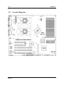
WI-2P Dual Socket 604 Workstation Board User’s Manual 4200-0303-22 Rev. 1.00 Copyright and Warranty Notice The information in this document is subject to change without notice and does not represent a commitment on part of the vendor, who assumes no liability or responsibility for any errors that may appear in this manual. No warranty or representation, either expressed or implied, is made with respect to the quality, accuracy or fitness for any particular part of this document. In no event shall the manufacturer be liable for direct, indirect, special, incidental or consequential damages arising from any defect or error in this manual or product. Product names appearing in this manual are for identification purpose only and trademarks and product names or brand names appearing in this document are property of their respective owners. This document contains materials protected under International Copyright Laws. All rights reserved. No part of this manual may be reproduced, transmitted or transcribed without the expressed written permission of the manufacturer and authors of this manual. WI-2P Contents Chapter 1. 1.1. 1.2. 1.3. Chapter 2. 2.1. 2.2. 2.3. 2.4. 2.5. Introduction .................................................... 1-1 Features & Specifications....................................................... 1-1 Package Checklist................................................................... 1-3 Layout Diagram...................................................................... 1-4 Hardware Setup.............................................. 2-1 Precautions ............................................................................. 2-1 Installing the Workstation Board ........................................... 2-2 Install Xeon CPU and Heatsink ............................................. 2-3 System Memory ..................................................................... 2-4 2.4.1. Memory Configuration Table ................................... 2-4 2.4.2. Installing and Removing Memory Modules............. 2-4 Connectors, Headers, and Switches ....................................... 2-6 2.5.1. ATXPWR1, ATX12V1: EPS12V Power Connectors .................................................................................. 2-6 2.5.2. FAN1~6: FAN Connectors....................................... 2-7 2.5.3. CCMOS1: CMOS Memory Clearing Header........... 2-8 2.5.4. FPIO1: Front Panel Switches and Indicators Header .................................................................................. 2-9 2.5.5. FDC1, IDE0/IDE1 Connectors:.............................. 2-10 2.5.6. PCI1 ~ PCI5: PCI Card Slots: ................................ 2-11 2.5.7. 6CHAUD1: 5.1-Channel Audio Interface Header . 2-12 2.5.8. USB1/USB3: Additional USB Ports Headers ........ 2-13 2.5.9. CD1, AUX1: Internal Audio Connector................. 2-14 2.5.10. IR1: Infrared Device Header .................................. 2-15 2.5.11. Back Panel Connectors:.......................................... 2-16 2.5.12. J4: RAID Card Connector ...................................... 2-17 2.5.13. JP4: Terminator/Raptor II RAID Card Selector ..... 2-18 2.5.14. SCSI1/SCSI2: Ultra 320 SCSI Channels Connector ................................................................................ 2-19 User’s Manual Chapter 3. 3.1. 3.2. 3.3. 3.4. 3.5. 3.6. Chapter 4. 4.1. 4.2. BIOS Setup...................................................... 3-1 Main Menu ............................................................................. 3-2 Advanced Menu ..................................................................... 3-6 3.2.1. Advanced BIOS Features ......................................... 3-6 3.2.2. Advanced Chipset Features ...................................... 3-9 3.2.3. Integrated Peripherals ............................................. 3-11 3.2.4. Power Management Setup ...................................... 3-16 3.2.5. PnP/PCI Configurations.......................................... 3-20 Security Menu ...................................................................... 3-22 PC Health Menu ................................................................... 3-23 Clk/Misc. Menu.................................................................... 3-25 Exit Menu ............................................................................. 3-26 Driver Installation .......................................... 4-1 Setup Items ............................................................................. 4-2 Installing Ultra320 SCSI Controller....................................... 4-3 4.2.1. Installing Windows 2000 with an Ultra320 SCSI Controller .................................................................. 4-3 4.2.2. Installing the Driver when Windows 2000 is Already Installed..................................................................... 4-3 4.2.3. Changing SCSI Boot Controllers in Windows 2000 .................................................................................. 4-4 Appendix A. Trouble Shooting ........................................... A-1 Appendix B. How to Get Technical Support ..................... B-1 WI-2P Introduction 1-1 Chapter 1. Introduction 1.1. Features & Specifications CPU • Supports Dual Intel Xeon processor (603-pin or 604-pin) Chipset • • • Intel E7505 chipset supports 400MHz/533MHz Front Side Bus Intel 82801DB (ICH4) supports PCI 2.2, Ultra DMA100 IDE protocol Intel 82870P2 (P64H2) supports PCI-X 66/100MHz Memory • • • Six 184-pin DIMM sockets support DDR200/DDR266 RAM module Supports up to 12GB (Registered ECC) Supports up to 8GB (Unbuffered, Non ECC) LAN • • Onboard Intel 82545EM (Kenai-64) Gigabit Ethernet Controller 10/100/1000 Mb Ethernet Graphics • AGP8x/4x AGP Pro SCSI • • Adaptec AIC-7902, Dual channel Ultra 320 controller on board. Support Adaptec SCSI RAID card - 2015S (Raptor II) or “Terminator” System BIOS • • • AWARD Plug and Play BIOS supports APM, DMI, and ACPI Write-Protect Anti-Virus function by AWARD BIOS 4M-bit Flash ROM I/O Slot • • 2 PCI 33MHz/32bit PCI slots 1 PCI-X 100MHz/64bit slot User’s Manual 1-2 Chapter 1 • • 2 PCI-X 100MHz/64bit slots (JP4 pin-1 and pin-2 shorted for Adaptec Terminator RAID card -- Default) or 2 PCI 66MHz/64bit (JP4 pin-2 and pin-3 shorted Adaptec Raptor II RAID card) 1 AGP Pro slot Multi I/O Functions • • • • • • • 1 floppy port 2 channels of bus master IDE ports supporting up to four Ultra DMA100 devices 1 parallel port, 2 serial ports and 1 game port PS/2 keyboard and PS/2 mouse connectors Support 6 USB ports Support AC97, 5.1Channel (Option) Support S/PDIF (Option) Miscellaneous • • WI-2P 24-pin and 8-pin EPS 12V power connectors Extend ATX form factor (12” x 13”) Specifications and information contained herein are subject to change without notice. Introduction 1-3 1.2. Package Checklist (1) WI-2P Workstation board (1) Brief Installation Guide (1) Driver & Utilities CD (1) Ribbon cable for (1) 3.5” floppy disk drive (2) Ribbon cables for master and slave IDE drives (1) 68-pin LVD/SE SCSI cable with terminator for 5 Ultra 320 SCSI devices (2) CPU Retention Mechanism (2) Retention Clips for 603-pin CPU (2) Retention Clips for 604-pin CPU (1) I/O Shield (1) 2-port USB 2.0 cable User’s Manual 1-4 1.3. Layout Diagram WI-2P Chapter 1 Introduction 1-5 Jumpers Description Default Setting CCMOS1 CMOS Clear Pins 1-2 Closed (Normal) JP4 RAID Card Selector (Terminator/Raptor II) Pins 1-2 Closed (“Terminator” RAID Card) Connectors Description 6CHAUD1 Optional ABIT CA-20 Interface Connector AGP1 Slot for AGP8x/4x AGP Pro Display Card ATX12V1 8-pin EPS12V Power Connector ATXPWR1 24-pin EPS12V Power Connector CD1/AUX1 Internal Audio Sources Connectors DIMM 0~5 DDR DIMM Slots FAN1 CPU1 Fan Connector (Speed monitoring support) FAN2 CPU2 Fan Connector (Speed monitoring support) FAN3 System Fan Connector (Speed monitoring support) FAN4/5/6 System Fan Connector (No speed monitoring support in BIOS menu) FDC1 Floppy Disk Drive Connector FPIO1 Front Panel Switches & Indicators Headers IDE0/IDE1 Hard Disk Drive Connectors IR1 Optional Infrared Devices Connector J4 Adaptec Zero Channel RAID Card Connector JP3 Chassis Intrusion Header PCI1/2 PCI 33MHz/32bit PCI3 PCI-X 100MHz/64bit PCI4/PCI5 PCI-X 100MHz/64bit (JP4 pin1-2 shorted) or PCI 66MHz/64bit (JP4 pin2-3 shorted) SCSI1 Ultra 320 SCSI Channel A Connector SCSI2 Ultra 320 SCSI Channel B Connector SMB1 System Management Bus (SMBus) Header USB1/USB3 Additional USB Ports Connectors User’s Manual 1-6 WI-2P Chapter 1 Hardware Setup Chapter 2. 2-1 Hardware Setup 2.1. Precautions Please pay attention to the following precautions before setting up any hardware. 1. Always switch off the power supply and unplug the power cord from the wall outlet before installing the board or changing any settings. 2. Ground yourself properly by wearing a static safety wrist strap before removing the board from the antistatic bag. 3. Hold the board by its edges. Avoid touching any component on it. 4. Avoid touching module contacts and IC chips 5. Place the board on a grounded antistatic surface or on the antistatic bag that came with the board. User’s Manual 2-2 Chapter 2 2.2. Installing the Workstation Board Before installing the workstation board, exam your chassis to ensure this workstation board fits into it. Your chassis should support Extend ATX form factor. 1. Face the side of the I/O ports toward the rear part of the chassis. 2. Locate the screw holes on the workstation board and the chassis base. 3. Place all the studs or spacers needed on the chassis base and have them tightened. 4. Line up all the screw holes on the board with those studs or spacers on the chassis. 5. Tightens all the screw holes. ATTENTION: To prevent shorting the PCB circuit, please REMOVE the metal studs or spacers if they are already secured on the chassis base and are without mounting-holes on the workstation board to align with. WI-2P Hardware Setup 2-3 2.3. Install Xeon CPU and Heatsink This workstation board provides you two Socket-604 sockets to install Intel Xeon CPU. The CPU you bought should have a kit of heatsink and cooling fan bundled together. If that’s not the case, buy one specially designed for Xeon Socket 604 CPU. Please refer to the diagram shown below to install CPU and heatsink. NOTE: This workstation board also supports the Xeon CPU of 603-pin package. NOTE: The diagram shown here is for reference only. Your retention mechanism may not be exactly the same as this type. Please follow the installation instruction of the heatsink you bought. User’s Manual 2-4 Chapter 2 2.4. System Memory This workstation board provides six 184-pin Double Data Rate (DDR) Dual Inline Memory Module (DIMM) slots for Registered ECC DIMM modules with memory expansion size up to 12GB. 2.4.1. Memory Configuration Table DIMM Registered ECC DIMM Module Total Memory 0 128MB, 256MB, 512MB, 1GB, 2GB 128MB ~ 2GB 1 128MB, 256MB, 512MB, 1GB, 2GB 128MB ~ 2GB 2 128MB, 256MB, 512MB, 1GB, 2GB 128MB ~ 2GB 3 128MB, 256MB, 512MB, 1GB, 2GB 128MB ~ 2GB 4 128MB, 256MB, 512MB, 1GB, 2GB 128MB ~ 2GB 5 128MB, 256MB, 512MB, 1GB, 2GB 128MB ~ 2GB Total System Memory 2.4.2. 256MB ~ 12GB Installing and Removing Memory Modules ATTENTION: Populate the DDR DIMMs in-order and in-pair (of the same type and size) by starting from DIMM0~DIMM1, DIMM2~DIMM3, to DIMM4~DIMM5. The System may hang or appear unstable if the DIMM ordering is not followed. WI-2P Hardware Setup 2-5 Power off the computer and unplug the AC power cord before installing or removing memory modules. 1. Locate the DIMM slot on the workstation board. 2. Hold two edges of the DIMM module carefully, keep away of touching its connectors. 3. Align the notch key on the module with the rib on the slot. 4. Firmly press the module into the slots until the ejector tabs at both sides of the slot automatically snaps into the mounting notch. Do not force the DIMM module in with extra force as the DIMM module only fit in one direction. 5. To remove the DIMM modules, push the two ejector tabs on the slot outward simultaneously, and then pull out the DIMM module. ATTENTION: As the static electricity can damage the electronic components of the computer or optional modules, make sure you are discharged of static electricity by touching a grounded metal object briefly before starting these procedures. User’s Manual 2-6 Chapter 2 2.5. Connectors, Headers, and Switches All the connectors, headers and switches mentioned here are depending on your system configuration. Some features you may (or may not) have to connect or to configure depending on the peripherals you have connected. WARNING: Always power off the computer and unplug the AC power cord before adding or removing any peripheral or component. Failing to so may cause severe damage to your workstation board and/or peripherals. Plug in the AC power cord only after you have carefully checked everything. 2.5.1. ATXPWR1, ATX12V1: EPS12V Power Connectors These two connectors connect to EPS12V power supply. This workstation board requires an EPS12V power supplier with 460W capacity at least for Pentium 4 Xeon CPU system. NOTE: The auxiliary 12V power (ATX12V1) is necessary to support Intel Xeon CPUs. Failing to provide such extra power will result in the system’s booting failure. WI-2P Hardware Setup 2.5.2. 2-7 FAN1~6: FAN Connectors • FAN1: CPU1 Fan • FAN2: CPU2 Fan • FAN3: System Fan • FAN4~FAN6: System Fan (No speed monitoring support in BIOS menu) User’s Manual 2-8 2.5.3. Chapter 2 CCMOS1: CMOS Memory Clearing Header This header uses a jumper cap to clear the CMOS memory. Short pin-2 and pin-3 only when you want to clear the CMOS memory. The default setting is pin-1 and pin-2 shorted for normal operation. ATTENTION: Turn the system power off first (including the +5V standby power) before clearing the CMOS memory. Failing to do so may cause your system to work abnormally or malfunction. WI-2P Hardware Setup 2.5.4. 2-9 FPIO1: Front Panel Switches and Indicators Header This header is used for connecting switches and LED indicators on the chassis front panel. Watch the power LED pin position and orientation. The mark “+” align to the pin in the figure below stands for positive polarity for the LED connection. • HD_LED: Connects to the HDD LED cable of chassis front panel. • RST: Connects to the Reset Switch cable of chassis front panel. • SPEAKER: Connects to the System Speaker cable of chassis. • SUS_LED: Connects to the Suspend LED cable (if there is one) of chassis front panel. • PWR_ON: Connects to the Power Switch cable of chassis front panel. • PWR_LED: Connects to the Power LED cable of chassis front panel. • KEY_LOCK: Connects to the Keylock cable (if there is one) of chassis front panel. User’s Manual 2-10 2.5.5. Chapter 2 FDC1, IDE0/IDE1 Connectors: The FDC1 connector connects up to two floppy drives with a 34-wire, 2-connector floppy cable. Connect the single end at the longer length of ribbon cable to the FDC1 on the board, the two connectors on the other end to the floppy disk drives connector. Generally you need only one floppy disk drive in your system. NOTE: The red line on the ribbon cable must be aligned with pin-1 on both the FDC1 port and the floppy connector. Each of the IDE port connects up to two IDE drives at Ultra ATA/100 mode by one 40-pin, 80-conductor, and 3-connector Ultra ATA/66 ribbon cables. Connect the single end (blue connector) at the longer length of ribbon cable to the IDE port of this board, the other two ends (gray and black connector) at the shorter length of the ribbon cable to the connectors of your hard drives. NOTE: Make sure to configure the “Master” and “Slave” relation before connecting two drives by one single ribbon cable. The red line on the ribbon cable must be aligned with pin-1 on both the IDE port and the hard-drive connector. WI-2P Hardware Setup 2.5.6. 2-11 PCI1 ~ PCI5: PCI Card Slots: PCI1/PCI2: PCI 33MHz/32bit PCI3: PCI-X 100MHz/64bit PCI4/PCI5: PCI-X 100MHz/64bit (JP4 pin-1 and pin-2 shorted for Adaptec Terminator RAID card -- Default) or PCI 66MHz/64bit (JP4 pin-2 and pin-3 shorted Adaptec Raptor II RAID card) User’s Manual 2-12 2.5.7. Chapter 2 6CHAUD1: 5.1-Channel Audio Interface Header This header provides 5.1-channel audio output through optional ABIT CA-20 interface. To enable the audio function on optional CA-20 interface, use the extension cable packed with CA-20 to connect both the 6CHAUD1 headers on CA-20 and this board. WI-2P Hardware Setup 2.5.8. 2-13 USB1/USB3: Additional USB Ports Headers These headers each provide two additional USB ports connection. Pin 1 3 5 7 9 Pin Assignment VCC Data0 Data0 + Ground NC Pin 2 4 6 8 10 Pin Assignment VCC Data1 Data1 + Ground NC To enable the USB function on optional CA-20 interface, use the extension cable packed with CA-20 to connect the JP1 header on CA-20 and the USB1 header on this board. User’s Manual 2-14 2.5.9. Chapter 2 CD1, AUX1: Internal Audio Connector These connectors connect to the audio output of internal CD-ROM drive or add-on audio card. WI-2P Hardware Setup 2.5.10. 2-15 IR1: Infrared Device Header This header connects to an optional IR device attached to chassis. This workstation board supports standard IR transfer rates. User’s Manual 2-16 2.5.11. Chapter 2 Back Panel Connectors: • Mouse: PS/2 mouse connector. • Keyboard: PS/2 keyboard connector. • LPT: Parallel port connector. • COM1/COM2: Serial port connector • LAN: Local Area Network connector. Left LED Off Green Green Right LED Off Off Blink Orange Definition No Connection Link Active • USB: Universal Serial Bus connector. • MIDI/GAME Port: Joystick, game pad, MIDI or other simulation hardware devices connector. • Line Out: Audio output jack. • Line In: Audio input jack. • Mic In: Microphone input jack. WI-2P Hardware Setup 2.5.12. 2-17 J4: RAID Card Connector The J4 connector can be used to setup a RAID system by installing an optional Adaptec RAID card - 2015S (Raptor II) or the latest “Terminator” to this connector. User’s Manual 2-18 2.5.13. Chapter 2 JP4: Terminator/Raptor II RAID Card Selector This header uses a jumper cap to select the RAID card from Terminator to Raptor II. Short pin-2 and pin-3 only when using Adaptec Raptor II RAID card. The default setting is pin-1 and pin-2 shorted for Adaptec Terminator RAID card. WI-2P Hardware Setup 2.5.14. 2-19 SCSI1/SCSI2: Ultra 320 SCSI Channels Connector Both SCSI1 and SCSI2 connectors provide two 68-pin Ultra 320 SCSI channels. Each channel supports up to 15 devices (ID0~ID15) on a standard Ultra 320 SCSI LVD (Low Voltage Differential) cable, configuration up to 12 meters. In a point-to-point arrangement, cabling can extend 25 meters. Each device has its own individual SCSI ID number, but none of the devices connected can use ID7, which is reserved for SCSI controller. User’s Manual 2-20 In order to prevent signal loss, a 68-pin twisted ribbon cable (LVD) with external SCSI terminator is necessary to connect Ultra 320 SCSI hard drive to this workstation board. All termination jumpers on the SCSI devices must be removed when using the external SCSI terminator. IMPORTANT: Each channel should have only one type of SCSI standard. A mixed setup with different standard on the same channel will decrease the performance to the slowest device. WI-2P Chapter 2 BIOS Setup Chapter 3. 3-1 BIOS Setup The BIOS is a program located in a Flash Memory chip on the workstation board. This program will not be lost when you turn the computer off. This program is also referred to as the boot program. It is the only channel the hardware circuit has to communicate with the operating system. Its main function is to manage the setup of the workstation board and interface card parameters, including simple parameters such as time, date, hard disk drive, as well as more complex parameters such as hardware synchronization, and device operating mode. The computer will operate normally, or will operate at its best, only if all of these parameters are correctly configured through the BIOS. Don’t change the parameters inside the BIOS unless you fully understand its meanings and consequences: The parameters inside the BIOS are used to setup the hardware synchronization or the device-operating mode. If the parameters are not correct, they will produce errors, the computer will crash, and sometimes you will not even be able to boot the computer after it has crashed. We recommend that you do not change the parameters inside the BIOS unless you are very familiar with them. If you are not able to boot your computer anymore, please refer to the section “CMOS Memory Clearing Header” in Chapter 2. When you start the computer, the BIOS program controls it. The BIOS first operates an auto-diagnostic test called POST (Power On Self Test) for all of the necessary hardware. It then configures the parameters of the hardware synchronization, and detects all of the hardware. After these tasks are completed, the operating system (OS) give up control of the computer to the next level. Since the BIOS is the only channel for hardware and software to communicate, it is the key factor for system stability, and in ensuring that your system performs at its best. After the BIOS has achieved the auto-diagnostic and auto-detection operations, it will display the following message: PRESS DEL TO ENTER SETUP NOTE: As the BIOS menu is being constantly improved to increase system stability and performance; the BIOS screens in this manual may not completely match those of your BIOS version. User’s Manual 3-2 Chapter 3 3.1. Main Menu Date (mm:dd:yy) This item allows you to set the date you specify (usually the current date) in the format of [Month], [Date], and [Year]. Valid values are [Month]: January ~ December, [Date]: 1 ~ 31, and [Year]: 1999 ~ 2099. Use the <Tab> or <Enter> key to move between the fields. Time (hh:mm:ss) This item allows you to set the time you specify (usually the current time) in the format of [Hour], [Minute], and [Second]. Valid values are [Hour]: 00 ~ 23, [Minute]: 00 ~ 59, and [Second]: 00 ~ 59. Use the <Tab> or <Enter> key to move between the fields. IDE Primary Master, IDE Primary Slave, IDE Secondary Master, and IDE Secondary Slave Move cursor to item “IDE Primary Master”, “IDE Primary Slave”, “IDE Secondary Master” or “IDE Secondary Slave”, and then press <Enter> key to enter a sub-menu. WI-2P BIOS Setup 3-3 IDE Primary/Secondary Master/Slave IDE HDD Auto-Detection This item allows you to detect the parameters of IDE drives by pressing the <Enter> key. The parameters will automatically be shown on the screen. IDE Primary Master When set to [Auto], the BIOS will automatically check what kind of IDE drive you are using. If you want to define your own drive by yourself, set it to [Manual] and make sure you fully understand the meaning of the parameters. Refer to the manual provided by the device manufacturer to get the settings right. Access Mode This item selects the mode to access your IDE devices. Leave this item to its default [Auto] settings to let BIOS detects the access mode of your HDD and makes decision automatically. Capacity This item automatically displays your HDD size. Note that this size is usually slightly greater than the size given by a disk-checking program of a formatted disk. NOTE: The following [Cylinder], [Head], [Precomp], [Landing Zone], and [Sector] items are available when you set the item “IDE Primary Master” to “Manual”. User’s Manual 3-4 Chapter 3 Cylinder When disks are placed directly above one another along the shaft, the circular vertical “slice” consisting of all the tracks located in a particular position is called a cylinder. You can set the number of cylinders for a HDD. The minimum number you can enter is 0, the maximum number you can enter is 65535. Head This is the tiny electromagnetic coil and metal pole used to create and read back the magnetic patterns on the disk (also called the read/write head). You can configure the number of read/write heads. The minimum number you can enter is 0, the maximum number you can enter is 255. Precomp The minimum number you can enter is 0, the maximum number you can enter is 65535. Landing Zone This is a non-data area on the disk's inner cylinder where the heads can rest when the power is turned off. The minimum number you can enter is 0, the maximum number you can enter is 65535. Sector The minimum segment of track length that can be assigned to stored data. Sectors usually are grouped into blocks or logical blocks that function as the smallest units of data permit. You can configure this item to sectors per track. The minimum number you can enter is 0, the maximum number you can enter is 255. WI-2P BIOS Setup 3-5 Drive A This item sets the type of floppy drives installed. [None]: No floppy drive installed [360K, 5.25 in.]: 5.25-inch standard drive; 360KB capacity [1.2M, 5.25 in.]: 5.25-inch AT-type high-density drive; 1.2MB capacity [720K, 3.5 in.]: 3.5-inch double-sided drive; 720KB capacity [1.44M, 3.5 in.]: 3.5-inch double-sided drive; 1.44MB capacity [2.88M, 3.5 in.]: 3.5-inch double-sided drive; 2.88MB capacity Halt On This item determines whether the system stops if an error is detected during system boot-up. [All Errors]: The system-boot will stop whenever the BIOS detect a non-fatal error. [No Errors]: The system-boot will not stop for any error detected. [All, But Keyboard]: The system-boot will stop for all errors but keyboard error. [All, But Diskette]: The system-boot will stop for all errors but disk error. [All, But Disk/Key]: The system boot will stop for all errors but disk or keyboard error. Base Memory This item displays the amount of base memory installed in the system. The value of the base memory is typically 640K for system with 640K or more memory size installed on the motherboard. Extended Memory This item displays the amount of extended memory detected during system boot-up. Total Memory This item displays the total memory available in the system. User’s Manual