1
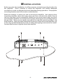
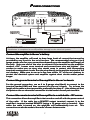
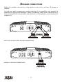
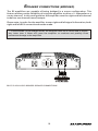
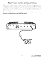
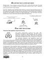
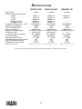
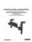
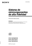
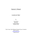
1
Dear customer,
Congratulations on your purchase of a Bazooka RS high-performance amplifier. At
Bazooka, we are fanatics about accurate music reproduction. Your selection of our
products for your sound system indicates that quality sound is also important to you
too. At SAS, we take great pride in manufacturing revolutionary audio products,
and through the years of engineering expertise, hand craftsmanship and critical
testing procedures, we have created the RS high-performance series of amplifiers.
We hope that you will take as much pride in owning and using one of these highquality audio products as we do designing and manufacturing them.
When properly installed and operated, your Bazooka RS amplifier will give you
years of clean uninterrupted sound reproduction. Therefore, we urge you to take a
few minutes to carefully read through this manual. It will explain all of the features
of your RS amplifier and help insure trouble free installation.
Sound can be deceiving. Over time your hearing comfort level adapts to higher
volumes of sound. What may have sounded normal can actually be too loud and
harmful to your hearing. Guard against this by setting your equipment at a safe
level before your hearing adapts.
To establish a “safe level”,
Start with your volume control at a low setting.
Slowly increase the volume control until you can hear comfortably, clearly
and without distortion.
Once you have established a comfortable “sound level”, make a note of
this position and do not go above this setting
Taking a minute to do this will help prevent your hearing from being damaged and
allow you to enjoy listening to music throughout your lifetime.
2
SAFETY PRECAUTIONS
Fuse amplifiers power wire at the battery.
Be sure to fuse the power wire within 12” of the car's battery. This will protect the
car's battery in case of a short circuit between the power amplifier and battery.
THIS IS A MUST, the amplifier's built-in fuse will only protect the power amplifier
not the car's battery!
Use high grade wire connectors.
To ensure maximum power transfer and secure safe connections, it is recommended
to use high grade barrier spades (for connection at amplifier) and terminal rings
(for connection at battery).
Do not run any wires underneath vehicle.
Exposed wires have a chance of being cut or damaged. It is best to run all wires
through the vehicle under the carpet and/or side panels. This lends to a cleaner
installation and less risk of damage.
Use caution when mounting amplifier.
Remember there are many electrical wires, gas lines, vacuum lines, brake lines as
well as a gas tank in the automobile. Make sure you know where they are when
mounting the amplifier to avoid puncturing lines, shorting wires or drilling holes in
the gas tank.
Run signal wires away from electrical wires.
To avoid possibility of induced noise from the car's electrical system (i.e. popping
noises or engine noise), run wires away from the car's electrical wiring.
Make all ground wires as short as possible and at the same point.
In order to reduce the chance of ground loops (i.e. engine noise), make the
grounding wire as short as possible to reduce the wire's resistance. Also, when
using multiple components, make sure all units are grounded at the same point.
Avoid sharp edges when running the wires.
To avoid the possibility of power, signal or speaker shorts, be careful not to allow
the amplifiers wires to come in contact with sharp edges. Use a grommet to protect
the wire when running through the fire wall .
3
FEATURES AND BENEFITS
DC Offset Protection
This circuit protects the output of the amplifier against DC voltage. If for some
reason DC voltage is detected at the output stage, the amplifier will shut down
protecting the speakers from direct current.
Short Circuit Protection
The circuit protects the amplifier from damage due to a short found in the speakers
or wiring. If one of the speakers or its wiring comes in contact with ground, the
amplifier will shut down. To resume normal operation, correct the problem and
turn the head unit off, then back on. The amplifier will reset and play again.
Thermal Protection
To protect the amplifier circuitry against damage caused by prolonged exposure to
high temperatures, a thermal protection circuit is activated if the amplifier reaches
excessively high operating temperature. Once the thermal circuit is activated, the
amplifier will shut down to cool off. The amplifier will automatically turn back on
once it cools down to a safe operating temperature.
Power Indicator
The diagnostic L.E.D. Illuminates green when the amplifier is on and receiving
power.
Tri Mode Capable (RS75.2HC & RS150.2HC)
If so desired, the amplifier may be run in stereo and mono at the same time. For
example, this feature would allow you to run a pair of mid and tweeters in stereo
and a sub-woofer mono (See Page 11).
Built-in Crossover
The “RS”amplifiers include a built-in variable **high and low pass crossovers. The
crossover features a variable frequency selection (60Hz ~ 400Hz) for precise high or
low pass filtering. **Except RSA800.1D which has a 40 ~ 200Hz low pass filter.
4
Bass Boost
For added low frequency performance the amplifiers are equipped with a variable
0~12 dB bass boost @ 45Hz.
Line Out
One set of full range line outputs have been provided for convenient connection to
additional amplifiers in the system.
Power Fusing
This protects the amplifier against short circuits and excessive current.
Remote Turn-on
Automatically turns amplifier on when connected to the head unit's remote
output. The amplifier will turn on and off with the head unit to save current
consumption. This control also operates the reset circuit for the amplifier's
protection. It must be connected with the head unit in order to reset protection
circuits.
Adjustable Input Sensitivity
Allows you to fine-tune the level matching between your source and the power
amplifier.
Stable To 1 Ohm in Stereo Mode
Stability to 1 ohm in stereo mode, 2 ohms bridged. The RSA800.1D is stable to 2
ohms mono.
5
MOUNTING LOCATION
Before you start the installation, it will be necessary to find a mounting location for
the amplifier. Find a location in which the amplifier will receive adequate
ventilation in order to dissipate the heat it develops during operation. Two popular
mounting locations are in the trunk or under the seat.
Select the location in which you wish to mount the amplifier. Use caution when
mounting amplifier, there are many wires, gas lines, vacuum lines, brake lines as
well as a gas tank in the automobile. Make sure you know where they are when
mounting the amplifier to avoid puncturing lines, shorting wires or drilling holes in
the gas tank. Once you are ready, use a pencil to mark the mounting holes in the
bottom panel. After you have marked the locations of the holes move amplifier out
of the way and drill small starter holes to make the tapping screws easier to install.
Use provided screws to tighten down the amplifier.
PWR/PRT
L
OUTPUT INPUT
LEVEL
FILTER
HIGH
BASS
LOW
FLAT
MIN MAX
R
X-OVER
L
40Hz
R
6
400Hz
0 dB 12dB
REMOTE
POWER CONNECTIONS
RSA800.1D
+12V
FUSE
25A
25A
REM
SPEAKER
GND
25A
IN-LINE POWER FUSE
MOUNTED WITHIN 12"
FROM BATTERY RECOMMENDED
RADIO'S REMOTE
TURN-ON OUTPUT
(NOT PROVIDED)
+
-
CAR BATTERY
+12V
94.7
IMPORTANT! Before making any connections, disconnect the car’s battery until the
installation is completed to avoid possible damage to the electrical system.
Connect the amplifier to the car's battery.
At times, the amplifier will need to draw large levels of current that cannot be
provided by any circuit in the car's fuse box. We recommended using an 4 to 8
gauge power wire for your connections depending on the amplifier and length of
the wire. Strip one end of the wire to connect to the terminal on the amplifier
marked +12V. Loosen screw terminal and connect bare wire and tighten. Use
caution to make sure no stray wire stands come in contact with surrounding
terminals causing short circuits. Run the wire directly to the positive terminal of the
car's battery. Make sure to use an in-line fuse within 12” of the car's battery to
protect the electrical system and amplifier against short circuits and/or power
surges.
Connect the ground terminal of the amplifier to the car's chassis.
For the ground connection, use an 4 to 8 gauge wire (black) to connect to the
terminal marked GND and then connect it to the car's chassis. Try to keep the
length of the cable as short as possible, preferably less than 6". Also make sure that
the point on the car where the connection is to be made is free of paint and dirt.
Connect the remote terminal of the amplifier to a switchable +12V source.
This connection allows the amplifier to be turned on and off with the power control
of the radio. If the radio has a REMOTE output terminal, connect it to the
amplifier's terminal marked REMOTE (using a 16 gauge wire or heavier). Now
when the radio is turned on, the amplifier will automatically turn on. This
connection can also be made to the radio’s Power Antenna wire.
7
SIGNAL CONNECTIONS
Connect the RCA output of the head unit (AM/FM cassette player, CD, or DAT) to
the RCA input terminals of the amplifier.
To make these connections, we recommend high quality RCA cables, which are
available at your local car audio retailer. Run signal wires away from electrical wires
to avoid possibility of induced noise from the car's electrical system (i.e. popping
noises or engine noise). Please note that when making these connections the signal
inputs correspond with the speaker outputs.
PWR/PRT
OUTPUT INPUT
LEVEL
L
L
R
R
FILTER
HIGH
MIN MAX
Optional full range line out
connection to additional amplifiers
in the system.
X-OVER
BASS
LOW
FLAT
60Hz
400Hz
0 dB 12dB
L
R
R
L
RSA75.2HC & RSA150.2HC SIGNAL CONNECTIONS
PWR/PRT
OUTPUT INPUT
LEVEL
L
L
R
R
MIN MAX
Optional full range line out
connection to additional amplifiers
in the system.
L
R
R
L
RSA800.1D SIGNAL CONNECTIONS
8
X-OVER
40Hz
200Hz
BASS
0 dB 12dB
REMOTE
REMOTE
SPEAKER CONNECTIONS
Make the speaker connections using speaker wire that is at least 16 gauge or
heavier.
As with any audio component, proper phasing of the amplifier and speakers is
essential for strong bass response. When connecting, make sure that positive (+)
from the amplifier is connected to the positive (+) of the speaker, and the same for
negative (-).
RSA75.2HC
FUSE
+12V
POWER
REM
GND
SPEAKER
BRIDGE
25A
25A
-
+
4 Ohm Speakers
(1 Ohm Minimum)
+
RSA75.2HC & RSA150.2HC SPEAKER CONNECTIONS
RSA800.1D
+12V
FUSE
25A
25A
REM
GND
SPEAKER
25A
+
-
RSA800.1D SPEAKER CONNECTIONS
4 Ohm Speaker
(1 Ohm Minimum)
9
-
SPEAKER CONNECTIONS (BRIDGED)
The RS amplifiers are capable of being bridged in a mono configuration. This
feature allows you the flexibility of using the amplifier to drive a ** subwoofer or a
center channel. In this configuration the amplifier sums the right and left channel
to deliver one channel (mono) output.
Please note: in order for the amplifier to sum right and left signal information, both
right and left RCA connections must be made.
**CAUTION! In the bridged mode, the amplifier must see a 2 Ohm load or higher.
Any lower than 2 Ohms will cause the amplifier to overheat and possibly cause
permanent damage to the amplifier!
RSA75.2HC
FUSE
+12V
POWER
REM
GND
SPEAKER
BRIDGE
25A
25A
+
-
4 Ohm Speakers
(1 Ohm Minimum)
RSA75.2 & RSA150.2 BRIDGED SPEAKER CONNECTIONS
10
SPEAKER CONNECTIONS (TRI-MODE)
The RSA75.2HC and RSA150.2HC are capable of running in a Mono / Stereo mode.
This feature gives the amplifier the ability to run stereo satellites (midbass &
tweeter) simultaneously with a mono subwoofer.
These connections are more complicated because they require the use of passive
crossover networks (Not provided) to divide the frequencies to the speakers. We
have included a sample diagram for 4 Ohm connections. If you wish to use multiple
speakers to achieve a lower impedance and higher power, it is strongly
recommended that you seek professional advice from your BAZOOKAd retailer
before attempting to make these connections.
Please Note: In the Tri-mode configuration, the amplifier’s built-in crossover must
be set to the ”FLAT” position so the speakers receive full range output.
RSA75.2HC
FUSE
+12V
POWER
REM
GND
SPEAKER
BRIDGE
25A
25A
100 F
G
NON-POLAR
CAPACITOR
E
N
D
+
100 F
4 mH
E
-
L
-
Left
Mid / Tweeter
4 Ohm
(1 Ohm Minimum)
+
INDUCTOR
(COIL)
-
Right
Mid / Tweeter
4 Ohm
(1 Ohm Minimum)
Mono Woofer
8 Ohm
(2 Ohm Minimum)
CAUTION!
In Tri- mode operation, the amplifier must see a 1 Ohm load or higher for
the stereo satellites and no lower than 2 Ohms for the subwoofer(s). Any lower than the
above mentioned impedance will cause the amplifier to overheat and possibly cause
permanent damage to the amplifier.
11
REMOTE BASS CONTROL MODULE (OPTIONAL)
Before connecting the remote, it will be necessary to find a mounting location that
will be easy to access for adjustment. Once you select your mounting location, you
will need to run the control wire from the remote to the amplifier. To avoid
possibility of induced noise from the car's electrical system (i.e. popping noises or
engine noise), run the cable from the remote to the amplifier away from the car's
electrical wiring.
Please note: Once the remote is plugged in, it overrides the bass boost on the
amplifier and becomes the primary bass adjustment.
PWR/PRT
OUTPUT INPUT
LEVEL
L
L
R
R
MIN MAX
X-OVER
40Hz
200Hz
BASS
0 dB 12dB
MIN
12
REMOTE
MAX
ADJUSTING THE X-OVER AND BASS
.
(Please note: If you intend to use the RSA75.2HC or RSA150.2HC in the Tri-mode
configuration, it is necessary to set the crossover control to the “FLAT” setting in
order to receive full range output)
The “RS” amplifiers are equipped with a built-in crossover network allowing you to
select the crossover type (i.e. Low-Pass or Hi-Pass) and the desired crossover point.
For example if you wish to drive a pair of subwoofers, you can select the “Low Pass”
setting on the amplifier to filter out high frequencies. This will send only low
frequencies to your subwoofers (see example settings below).
Select the crossover type on the
amplifiers side panel.
(Low-pass is selected in this example for subwoofers)
You can add up to 12dB bass boost by
increasing the Bass Boost control.
X-OVER
FILTER
HIGH
LOW
FLAT
BASS
BOOST
60Hz 400Hz
0dB 12dB
Select the crossover
point for your speakers.
(RSA800.1D is 40 ~ 200Hz)
FINE TUNE THE SYSTEM
Fine tune the amplifier's input sensitivity.
LEVEL
The gain sensitivity control for the “RS”
amplifier is located on the side panel. This gain control
has been included to allow adjustment to properly
match the output of the radio. This is one of the most
misunderstood adjustments. By rotating the control in
MIN MAX
the clockwise direction, the amplifier‘s input will
become more sensitive and the music will play louder.
This is not a volume control and you will not get more power out of the amplifier in
the maximum position! It may seem to deliver more output, but actually the
system is only playing louder faster as you turn the volume control on the radio.
Ideally, to properly level match the system the goal is to achieve maximum output
from the amplifier without distortion at about 3/4 of the volume control.
To determine if the amplifier’s gain is set properly, turn the system on and slowly
increase the volume control. You should be able to use about 3/4 volume before
the system gets loud but not distorting. It is very important when making these
adjustments that you do not over drive the speakers (at point of distortion) this will
cause permanent damage to the speakers. If you are unable to achieve 3/4 volume
before distortion you will need to adjust gain control (in this case you would reduce
the gain). The gain controls should be adjusted very slowly. It may help to have
another person to assist you by adjusting the gain controls while you listen for
distortion.
13
TROUBLE SHOOTING THE SYSTEM
We have put together this trouble-shooting guide if you experience problems after
installing the amplifier. Please keep in mind that the majority of problems incurred
are caused by improper installation and not the equipment itself. In addition, there
are many components in the system that could cause various signal problems such as
inducted electrical noise and engine noise.
Before you can properly address the problem, you must first find the component
that is causing the problem. This will take patience and a process of elimination.
LOOK FOR....
SOLUTION
No Output
Blown fuse
Bad RCA Cable(s)
+12V at power terminal
+12V at remote terminal
Grounding point clean and tight
Head Unit's fader not in center position
Replace
Replace
Check connection
Check connection
Check for ground w/meter
Set to center position
Low Output
Check level adjustments
Bad RCA cable(s)
Improper level matching
Re-adjust
Replace
Re-adjust
Engine Noise
Grounding points are clean and tight
Ground all components at same point
Try different grounding point
Bad RCA cable(s)
Use High Quality shielded RCA cables
Low Vehicle charging system and/or battery
Check for ground w/meter
Ground at same point
Change for better ground
Replace
Rejects inducted noise
Fix and/or replace
Red Protection L.E.D. Illuminated
Speaker short
Check speakers connection
for short circuit
Make sure speaker wires
do not touch chassis ground
Check speaker impedance
(Min 2 ohm Stereo, 4 Mono)
Check mounting location
for Adequate air Circulation
Speaker impedance too low
Speaker grounding out
Impedance too low
Overheating
14
SPECIFICATIONS
RSA75.2HC
RSA150.2HC
Max Power
750W
1200W
Output Power @ 14.4 VDC :
4 ohm
75W x 2
150W x 2
2 ohm
110W x 2
220W x 2
1 ohm
140W x 2
280W x 2
Bridged 4 ohm
220W x 1
450W x 1
Bridged 2 ohm
280W x 1
560W x1
Frequency Response + - 1dB
20Hz-22KHz
20Hz-22KHz
S/N Ratio (A-weight)
>90dB
>90dB
THD with 80k filter
.10%
.10%
Low Input Level
200mV-6V
200mV-6V
Battery Voltage Range
10.5VDC-15.0VDC 10.5VDC-15.0VDC
Crossover Type
HP/FULL/LP
HP/FULL/LP
Crossover Freq. (Variable)
60 ~ 400Hz
60 ~ 400Hz
Crossover Slope
18dB/Oct
18dB/Oct
Bass Boost @ FULL/LP
0 ~ 12dB
0 ~ 12dB
Unbalanced Input (RCA Jack)
Yes
Yes
Jack for Remote Control
Yes
Yes
Amplifier Fuse & Holder
2 x 25A
2 x 35A
Size (L x W x H)
16 1/4” x 9 3/4” x 2 1/4” 20 1/8” x 9 3/4” x 2 1/4”
RSA800.1D
1500W
500W x 1
800W x 1
---------20Hz-200Hz
>90dB
.10%
200mV-6V
10.5VDC-15.0VDC
LP
40 ~ 200Hz
12dB/Oct
0 ~ 12dB
Yes
Yes
3 x 25A
18 1/4” x 9 3/4” x 2 1/4”
Due to continuing product improvement, specifications subject to change without notice.
15
LIMITED WARRANTY
Southern Audio Services, Inc., warrants all products to be free from defects in material
and workmanship for a period of one (1) year from the date of purchase; the Reference
Series is warranted for a period of two (2) years from date of purchase. In the event the
product is not as warranted, SAS’ sole obligation shall be to repair or replace the
defective product at SAS’ option: SAS limits its obligation under any implied warranties
under state laws to a period not to exceed the limited warranty period. SAS and its
authorized BAZOOKA® dealers specifically disclaim liability for any incidental or
consequential damages. Some states do not allow limitations on how long an implied
warranty lasts, and some states do not allow the exclusion or limitation of incidental or
consequential damages, so the above limitation or exclusions may not apply to you. This
warranty gives you specific legal rights, and you may have other rights, which vary from
state to state.
What is covered: This warranty covers all defects in materials or workmanship (parts and
labor) in the product.
What is not covered: This warranty does not cover the following:
1. Damages occurring during shipment of the product to SAS for repair
(Claims must be presented to the carrier).
2. Damages caused by accident, abuse, negligence, misuse or improper
Operation o r installation.
3. Damages caused by an act of God, including without limitation, fire, flood
Storm or other acts of nature.
4. Any product, which has a serial number, defaced, altered, modified, or
removed.
5. Any product that has been altered or modified without SAS’ consent.
16
How to obtain warranty services:
1. You are responsible for delivery of the product to an authorized BAZOOKA® dealer
or contact SAS at 1-800-THE TUBE for a Return Authorization number. The Return
Authorization number must be clearly written on the outside of the box. Freight must
be prepaid to SAS. Warranty replacement parts will be returned freight prepaid. The
entire enclosure may be returned for warranty service, but return will be freight collect.
2. You must provide proof of the date of purchase of the product. If proof of purchase
is not provided, original date of manufacture will be used to determine warranty period.
3. You must package the product securely to avoid damage during shipment.
4. After acquiring a Return Authorization number, ship to the address below. Please
complete this section and retain for your records.
Model(s) purchased ____________________________________________________________
Serial number(s) _______________________________________________________________
Date Purchased ________________________________________________________________
Dealer’s name _________________________________________________________________
17
18