1
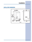
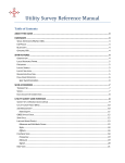
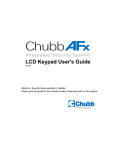
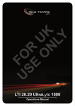
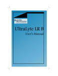
9/2/03
3:45 PM
Page 1
P.O. Box 245040
Milwaukee, WI 53224-9540
Phone 414.354.0300
FAX 414.354.7905
www.U-Line.com
Printed in U.S.A.
P/N 41923 (Rev. 08/03)
R
R
R
User’s Manual
Cover 41923
ICE-MAKERS,
COMBOS AND
REFRIGERATORS
Inside Front Cover 41923
9/2/03
3:45 PM
Page 1
U-LINE CORPORATION LIMITED WARRANTY
U-Line Corporation warrants each U-Line product to be free from defects in materials and
workmanship for a period of one year from the date of purchase; and warrants the sealed
system (consisting of the compressor, the condenser, the evaporator, the hot gas bypass
valve, the dryer and the connecting tubing) in each U-Line product to be free from defects
in materials and workmanship for a period of five years from the date of purchase. During
the initial one-year warranty period for all U-Line products U-Line shall: (1) at U-Line’s
option, repair any product or replace any part of a product that breaches this warranty; and
(2) for all Marine, RV and Domestic U-Line products sold and serviced in the United States
(including Alaska and Hawaii)and Canada, U-Line shall cover the labor costs incurred in
connection with the replacement of any defective part. During years two through five of the
warranty period for the sealed system, U-Line shall:. (1) repair or replace any part of the
sealed system that breaches this warranty; and (2) for all Marine, RV and Domestic U-Line
products sold and serviced in the United States (including Alaska and Hawaii)and Canada,
U-Line shall cover the labor costs incurred in connection with the replacement of any defective part of the sealed system. All other charges, including transportation charges for
replacements under this warranty and labor costs not specifically covered by this warranty, shall be borne by you. This warranty is extended only to the original purchaser of
the U-Line product. The Registration Card included with the product should be promptly
completed by you and mailed back to U-Line or you can register on-line at
www.U-LineService.com.
The following are excluded from this limited warranty: installation charges; damages
caused by disasters or acts of God, such as fire, floods, wind and lightening; damages
incurred or resulting from shipping, improper installation, unauthorized modification, or misuse/abuse of the product; customer education calls; food loss/spoilage; door and water
level adjustments (except during the first 90 days from the date of purchase); defrosting the
product; adjusting the controls; door reversal; or cleaning the condenser.
If a product defect is discovered during the applicable warranty period, you must promptly
notify either the dealer from whom you purchased the product or U-Line at P.O. Box 23220,
Milwaukee, Wisconsin 53223 or at 414-354-0300. In no event shall such notification be
received later than 30 days after the expiration of the applicable warranty period. U-Line
may require that defective parts be returned, at your expense, to U-Line’s factory in
Milwaukee, Wisconsin, for inspection. Any action by you for breach of warranty must be
commenced within one year after the expiration of the applicable warranty period.
This limited warranty is in lieu of any other warranty, express or implied, including,
but not limited to any implied warranty of merchantability or fitness for a particular
purpose; provided however, that to the extent required by law, implied warranties are
included but do not extend beyond the duration of the express warranty first set
forth above. U-Line’s sole liability and your exclusive remedy under this warranty is
set forth in the initial paragraph above. U-Line shall have no liability whatsoever for
any incidental, consequential or special damages arising from the sale, use or installation of the product or from any other cause whatsoever, whether based on warranty (express or implied) or otherwise based on contract, tort or any other theory
of liability.
Some states do not allow limitations on how long an implied warranty lasts or the exclusion
or limitation of incidental or consequential damages, so the above limitations may not apply
to you. This warranty gives you specific legal rights, and you may also have other rights
which vary from state to state.
Users Manual 41923
9/2/03
3:44 PM
Page 1
INTRODUCTION
Congratulations on your purchase of U-Line ice making or refrigeration
products. A pioneer in the field for more than 30 years, U-Line is the
world’s number one manufacturer of built-in, under-counter ice making
and specialty refrigeration products. U-Line dedicates 100% of its
research and development to these products. The result: U-Line technology leads the market with new ideas and superior craftsmanship.
U-Line also backs customers with a strong dealer network. U-Line’s
commitment to quality even extends to environmentally safe packaging.
U-Line products are making life more convenient in homes, business,
and hotels around the world.
PLEASE READ all instructions completely before attempting
to install or operate the unit. All models of Ice Makers and
Combos require a connection to the water supply and
improper hook-up can result in substantial property damage! If you are unsure of your ability to safely connect the
water supply to the unit, consult a licensed plumber for
assistance.
Once you have your unit installed, we suggest that you keep this manual in a safe place for future reference. Should any problems occur,
refer to the TROUBLESHOOTING section of this manual. This information will help you to quickly identify a problem and get it remedied. In the
event you require assistance, please contact the dealer where you purchased your unit.
PLEASE RECORD YOUR MODEL’S INFORMATION
Whenever you call to request information or service, you will need to
know your model number and serial number. You can find this information on the serial plate located on the inside wall of your unit.
Please also record the purchase date of your U-Line unit and your dealer’s name, address and telephone number.
Model Number:
________________________________________
Serial Number:
________________________________________
Puchase Date:
________________________________________
Dealer Name:
________________________________________
Dealer Address:
________________________________________
Dealer Telephone:
________________________________________
Keep this manual and the sales slip together in a safe place for further reference.
1
Users Manual 41923
9/2/03
3:44 PM
Page 2
User’s Manual
TABLE OF CONTENTS
INTRODUCTION..........................................................................1
SAFETY PRECAUTIONS ...............................................................3
INSTALLATION ...........................................................................5
CONNECTING THE WATER SUPPLY ..............................................7
LEVELING THE UNIT ...................................................................9
GRILLE INSTALLATION ................................................................9
GLASS SHELF INSTALLATION.....................................................12
REVERSING THE DOOR .............................................................13
REVERSING A STAINLESS STEEL DOOR.......................................18
ALIGNING THE DOOR................................................................18
CUSTOM DOOR PANEL INSERT INSTALLATION ............................19
BUILT-IN INSTALLATION.............................................................21
INITIAL START-UP.....................................................................23
NORMAL OPERATION ...............................................................24
MARINE USE ...........................................................................26
ADJUSTING THE TEMPERATURE CONTROL.................................26
ADJUSTING ICE CUBE SIZE .......................................................27
CARE AND CLEANING ..............................................................28
DEFROSTING ...........................................................................30
STORAGE ................................................................................30
TROUBLESHOOTING .................................................................31
IF SERVICE IS REQUIRED ...........................................................33
SPECIFICATIONS.......................................................................33
2
Users Manual 41923
9/2/03
3:44 PM
Page 3
SAFETY PRECAUTIONS
Do not attempt to install or operate your unit until you have read the
safety precautions in this manual. Safety items throughout this manual
are labeled with a Danger, Warning or Caution based on the risk type.
DEFINITIONS
!
This is the safety alert symbol. It is used to alert you to
potential personal injury hazards. Obey all safety messages
that follow this symbol to avoid possible injury or death.
! DANGER !
DANGER indicates an imminently hazardous situation
which, if not avoided, will result in death or serious injury.
!
WARNING indicates a potentially hazardous situation
which, if not avoided, could result in death or serious injury.
!
CAUTION indicates a potentially hazardous situation which,
if not avoided, may result in minor or moderate injury.
CAUTION
CAUTION used without the safety alert symbol indicates a
potentially hazardous situation which, if not avoided, may
result in property damage.
Indicates installation, operation or maintenance information
which is important but not hazard-related.
3
Users Manual 41923
9/2/03
3:44 PM
Page 4
User’s Manual
GENERAL PRECAUTIONS
! DANGER !
Risk of child entrapment. Before you throw away your old
refrigerator or freezer: Take off the doors, leave shelves in
place so that children may not easily climb inside.
!
• Never attempt to repair or perform maintenance on the
unit until the electricity has been disconnected.
• Altering, cutting of power cord, removal of power cord,
removal of power plug, or direct wiring can cause serious
injury, fire and/or loss of property and/or life and will
void the warranty.
!
• Do not lift unit by door handle.
• Use care when moving the unit. Some edges are sharp
and may cause personal injury. Wear gloves when moving or positioning the unit.
• Never install the unit behind closed doors. Be sure front
grille is free of obstruction. Obstructing free air flow can
cause the unit to malfunction, and may void the warranty.
• Allow unit temperature to stabilize for 24 hours before use.
• Never use an ice pick or other sharp instrument to help
speed up defrosting. These instruments can puncture
the inner lining or damage cooling unit.
• Failure to clean the condenser every three months can
cause the unit to malfunction. This could void the
warranty.
CAUTION
• Using a heater to speed up defrosting can damage the
inner lining. DO NOT use any type of electrical heater to
defrost.
• Use only genuine U-Line replacement parts. Imitation
parts can reduce ice rate, cause water to overflow from
ice maker mold, damage the unit, and may void the
warranty.
4
Users Manual 41923
9/2/03
3:44 PM
Page 5
INSTALLATION
SITE PREPARATION
1.
Position the unit on a flat, level surface, capable of supporting the
entire weight of the unit. Remember that the unit will be significantly heavier once it is fully loaded.
2.
Connect the unit to a grounded and polarized 115 VAC, 60Hz,
15A circuit (normal household current).
! DANGER !
ELECTROCUTION HAZARD!
Electrical Grounding Required. This appliance
is equipped with a three prong (grounding)
polarized plug for your protection against
possible shock hazards.
• NEVER remove the round grounding prong from the plug.
• NEVER use a two-prong grounding adapter.
• NEVER use an extension cord to connect power to the
unit.
Where a two-prong wall receptacle is encountered or a
longer power cord is required, contact a qualified electrician
to have it replaced in accordance with applicable electrical
codes.
5
Users Manual 41923
9/2/03
3:44 PM
Page 6
User’s Manual
NOTE
Keep in mind that the door of
the unit may be mounted on
either side of the cabinet (see
REVERSING THE DOOR). All
U-Line units have a zero clearance for the door to open
when the handle is on the
right (see Figure 1).
Additional clearance is needed for Combo Models 29A,
29FF, and 75A only, when the
door handle is on the left. See
BUILT-IN INSTALLATION for
additional clearance requirements for these models.
CABINET
OR WALL
DOOR
SWING
0"
CLEARANCE
NEEDED
UL124
Figure 1
3.
On Ice Maker models SP18, BI-95, BI-98 and Combo Series 29
and 75, install a 1/4 inch copper water line (not supplied with unit)
from the nearest COLD water pipe. When connecting the water
supply, follow these guidelines:
• Review the local plumbing codes before you install the unit.
• In most instances, the cold water supply will come from the
basement through a hole in the floor.
• The water pressure should be between 15 and 150 psi.
• Install a SHUT-OFF VALVE in the 1/4 inch supply line.
• Connect sufficient tubing to the unit to allow the unit to be
moved for cleaning and servicing. However, make certain that
the tubing is not pinched or damaged during installation.
• U-Line recommends the use of copper tubing for installation.
4.
Position the unit to allow free
air flow through the front grille
(see Figure 2).
5.
Wipe out inside of unit and ice
bucket with a damp cloth.
UL005A
Figure 2
6
Users Manual 41923
9/2/03
3:44 PM
Page 7
CONNECTING THE WATER SUPPLY
1.
Install the 1/4 inch copper
water line from the main
water source. On ice maker
models BI-95 and BI-98, the
water line is inserted
through the hole in the rear
of the unit to connect to the
solenoid valve in the front
(see Figure 3).
3.
Carefully bend the water supply line into position and connect the line to the solenoid
valve (see Figures 5 and 6).
Avoid kinking the water supply line.
WATER
CONNECTION
POWER
CORD
WATER LINE
UL101
Figure 3
2.
Locate the compression fitting and ferrule packed in the
unit. Slide the compression
fitting and ferrule over the
1/4 inch water supply line.
Do not use thread sealing
compound or tape. Using
two wrenches, tighten the
compression fitting on the
supply line (see Figure 4).
UL103
Figure 5
WATER LINE
UL104
UL134
Figure 6
Figure 4
7
Users Manual 41923
9/2/03
3:44 PM
Page 8
User’s Manual
4.
For recessed installations,
allow extra water supply line
length to provide slack for easy
removal from the recessed
area (see Figure 7). This will
also safeguard against kinking
the line.
NOTE
If you are not intending
to use the ice maker and
do not connect the water
supply (or turn the supply
valve off), it is imperative
to raise the bin arm of
the ice maker (see Figure
8).
UL002A
Figure 8
UL100
Figure 7
NOTE
After completing the installation, turn on the water and
recheck water connection for leaks. Apply additional tightening if needed. Do not use thread sealing compound or
tape.
NOTE
On Models BI-95 and BI-98, route the water supply line
through the unit in such a way as to prevent the line from
coming in contact with any internal components other than
the solenoid valve (see Figure 6). Normal operation creates
some vibration. A water supply line contacting an internal
component or cabinet wall may cause excessive noise during operation or damage to the line.
5.
Install the grille. See GRILLE INSTALLATION.
6.
Plug in the power cord.
7.
Gently push the unit into position. If desired the unit may be recessed
into cabinet or wall.
8
Users Manual 41923
8.
9/2/03
3:44 PM
Page 9
Allow at least 1-1/2 inches clearance behind the unit for electrical and water supply connections.
LEVELING THE UNIT
It is important that the unit, primarily the ice maker assembly, is level.
All 75 and 15 Series units are equipped with adjustable feet for leveling and height adjustment (see Figure 9). All other units have rubber
feet.
TURN FOOT TO ADJUST
UL105
Figure 9
GRILLE INSTALLATION
NOTE
Model SP18 Icemakers come with the grille already
installed.
29 AND 75 MODELS
1.
With a standard blade screwdriver (or 1/4” nutdriver), remove
the screw needed to attach the grille (see Figure 10).
2.
Remove the control knob by pulling it toward you.
3.
Carefully remove the grille from inside the unit. A small screw hole
is located toward the top of the middle recessed section of the
grille.
9
Users Manual 41923
9/2/03
3:44 PM
Page 10
User’s Manual
GRILLE SCREW
UL106
Figure 10
4.
Place the two hook-hinges (located on the rear bottom side of the
grille) on the front lip of the unit base. Swing the grille up into position, aligning the grille and cabinet screw holes (see Figure 11).
UL107
Figure 11
5.
Insert the screw, being careful not to over tighten.
6.
Reinstall control knob.
10
Users Manual 41923
9/2/03
3:44 PM
Page 11
95 AND 98 MODELS
1.
With a standard blade screwdriver (or 1/4" nutdriver), remove
the screw needed to attach the grille (see Figure 12).
2.
Carefully remove the grille from inside the
unit. Locate the screw hole at the top,
middle recessed section of the grille.
3.
Place the two hook-hinges (located on the
rear bottom side of the grille) on the front
lip of the unit base. Swing the grille up into
position, aligning the grille and cabinet
screw holes (see Figure 13).
UL501
Figure 12
GRILLE SCREW
UL502
Figure 13
4.
Insert the screw, being careful not to over tighten.
11
Users Manual 41923
9/2/03
3:44 PM
Page 12
User’s Manual
GLASS SHELF INSTALLATION
(FOR MODELS WITH GLASS SHELVES)
1.
Carefully remove the shelves from inside the unit and remove the
packaging.
2.
Slide the shelves onto desired ribs, making sure that the silver
edge strip is toward the front of the unit and the decorative graphics are on the underside of the shelves. Make sure the shelves are
inserted fully into the unit (see Figure 14). The white edge strip
towards the rear (Models 15R, 29R and 75R only) prevents cans
and bottles from freezing against the cold evaporator.
UL108
Figure 14
NOTE
Be sure to place shelves with the silver edge to the front
and decorative graphics on the underside.
12
Users Manual 41923
9/2/03
3:44 PM
Page 13
REVERSING THE DOOR
Depending upon the location of the unit, it may be desirable to change
the side on which the door is mounted.
NOTE
On Combo Models 29A and 29FF (built-in installations only),
changing the door mounting to the left side may interfere
with ice bucket removal. See BUILT-IN INSTALLATION section for clearance requirements.
To reverse the door mounting on Models SP18, BI-95, BI-98, 15R,
29R, Combo 29A, and Combo 29FF (except Stainless Steel models),
perform the following:
1.
Remove grille (1 screw). See
Figure 15.
2.
Remove top hinge from cabinet
(3 screws). See Figure 16.
Hold door to keep it from
falling.
REMOVE SCREW
UL116
Figure 15
UL109
Figure 16
3.
Lift the door off the bottom hinge.
4.
Remove bottom hinge from cabinet (2 screws) (see Figure 17).
Remove screws on opposite side of cabinet (see Figure 18). Note
that there may be a nut behind one or both screws on either side.
5.
Install hinge on opposite side, bottom of cabinet (see Figure 19).
Replace nut on back side where installed. Align hinge outer edge
with cabinet before tightening screws.
13
Users Manual 41923
9/2/03
3:44 PM
Page 14
User’s Manual
UL111
UL112
Figure 19
Figure 17
BUSHING
UL113
UL110
Figure 20
Figure 18
6.
Relocate plastic spacer/bushing on bottom of door to opposite
side, and place door on bottom hinge pin (see Figure 20). Clean
out bushing hole in door bottom with a screwdriver if needed.
7.
Remove plastic hole plug from door handle and relocate on opposite side. See Figure 21.
14
Users Manual 41923
8.
9/2/03
3:44 PM
Page 15
Remove pivot screw from top hinge, invert screw and reinstall
pivot screw in top hinge. See Figure 19.
HINGE
RIGHT SIDE
DOOR SWING
LEFT SIDE
DOOR SWING
PLASTIC
PLUG
HOLE
PLASTIC
PLUG
HOLE
RIGHT SIDE
HINGE
SCREW
INVERT
SCREW
INVERT
HINGE
UL115
Figure 21
9.
Remove three plastic screw 11. Fasten upper hinge to unit (3
plugs in hinge holes, top of
screws). Partially tighten
cabinet, opposite side. Be
screws until door is aligned.
careful not to scratch cabiSee Figure 23.
net (see Figure 22).
UL114A
Figure 22
10. Place door on lower hinge
pin. Invert and install upper
hinge on door.
UL119
Figure 23
15
Users Manual 41923
9/2/03
3:44 PM
Page 16
User’s Manual
12. Adjust door to assure proper seal. Tighten upper hinge screws
securely.
13. Replace three plastic plugs removed in step 8 into holes on top of
unit. Replace screws in holes in bottom of unit, opposite side.
14. Reinspect door seal and alignment. Adjust if needed.
15. Reinstall grille (1 screw).
NOTE
On Combo Model 75A (built-in installations only), changing
the door mounting to the left side may interfere with ice
bucket removal. See BUILT-IN INSTALLATION section for
clearance requirements.
To reverse the door mounting on Models Combo 75A and 75R
(except Stainless Steel models) perform the following:
1.
Remove grille (1 screw). See Figure 15.
2.
Remove top hinge from cabinet (4 screws). See Figure 16. Hold
door to keep it from falling.
3.
Lift the door off the bottom hinge.
4.
Remove four plastic plugs in hinge holes, top of cabinet, opposite
side (see Figure 22). Be careful not to scratch cabinet.
5.
Remove pivot screw from top
hinge, invert screw and reinstall pivot screw in top hinge.
See Figure 21. Do not install
hinge on cabinet at this time.
6.
Remove bottom hinge from
cabinet (4 screws) and
screws on opposite side of
cabinet (see Figure 24).
7.
Remove pivot screw from
bottom hinge, invert screw
and reinstall pivot screw in
hinge (see Figure 21).
UL128
Figure 24
16
Users Manual 41923
9/2/03
3:44 PM
Page 17
8.
Install bottom hinge on cabinet, opposite side, aligning
flat edge of hinge with outer
edge of unit. Partially tighten
screws. See Figure 25.
9.
Relocate plastic spacer/
bushing on bottom of door to
opposite side, and place door
on bottom hinge pin (see
Figure 20). Clean out bushing hole in door bottom with
a screwdriver if needed.
UL129
Figure 25
10. Place door on lower hinge pin. Align flat edge of top hinge with
outer edge of unit and fasten upper hinge to unit (4 screws).
Partially tighten screws until door is aligned. See Figure 23.
11. Adjust door to assure proper seal. Tighten upper and lower hinge
screws securely.
12. Replace four plastic plugs removed in step 5 into holes on top of
unit. Replace screws in holes in bottom of unit, opposite side.
13. Reinspect door seal and alignment. Adjust if needed.
14. Reinstall grille (1 screw).
17