1
™
LCD Keypad User's Guide
rev1.3
Attention: Security Representative / Installer,
Please give this guide to the customer before beginning work on the system.
Contents
For topics not listed here, please see the Index
Welcome..................................................................................................................................... 1
The Chubb AFx™ LCD Keypad............................................................................................................ 2
Alarms, Turning Protection On and Off .................................................................................. 5
Alarm Monitoring Features ................................................................................................................... 6
Audible Keypad Tones ......................................................................................................................... 6
Sirens ................................................................................................................................................... 7
Dealing with Alarms (what to do if the keypad is beeping) ................................................................... 7
Silencing a False Alarm ........................................................................................................................ 7
Using the Emergency Keys .................................................................................................................. 8
Worklate: Extending the Scheduled Closing Time............................................................................... 8
Suspending Schedules for an Area or Areas........................................................................................ 9
Turning Protection ON, STAY, or Viewing the Present Arming-Level................................................... 9
Turning Protection OFF ...................................................................................................................... 10
Turning Protection On by Area Groups, a Group of Areas or Individual Areas................................... 10
Area Priority Protection On/Off ........................................................................................................... 11
Common Area Protection On/Off........................................................................................................ 11
Turning ON an Area’s Protection using an Access TOKEN................................................................ 11
Turning OFF an Area’s Protection using an Access TOKEN.............................................................. 11
UK System Operation......................................................................................................................... 12
UK and European System Operation ................................................................................................. 12
Checking Status and Controlling Items ................................................................................ 15
Status and Control Features............................................................................................................... 16
Using the Function Keys..................................................................................................................... 16
Checking the System Status (monitored conditions for a system control unit) ................................... 16
Checking the Status of Sensors (Points) and Areas........................................................................... 17
Bypassing or Isolating a Faulty Sensor............................................................................................... 17
Checking Status or Controlling Readers or Doors .............................................................................. 18
Checking the Status or Controlling an Elevator Reader ..................................................................... 19
Checking the Status of an Application Module (POD) ........................................................................ 19
Administration and Maintenance Tasks ............................................................................... 21
Changing Your Own PIN .................................................................................................................... 22
Adding a User to the System .............................................................................................................. 22
Default Authority Settings ................................................................................................................... 23
Viewing or Changing Settings for a User............................................................................................ 24
Deleting a User................................................................................................................................... 26
Setting the Date and Time .................................................................................................................. 26
Manually calling the Director PC from the LCD Keypad: .................................................................... 27
Viewing the History............................................................................................................................. 27
Printing the History Log ...................................................................................................................... 28
Changing the Printed History Language............................................................................................. 28
Testing Monitored Sensors (Performing a Walk Test) ....................................................................... 29
Testing Panic Buttons (Performing a Hold-up Test) ........................................................................... 30
Testing Sirens (System Test) ............................................................................................................. 30
Reference Topics .................................................................................................................... 31
System Information............................................................................................................................. 32
500-3650E rev1.3 (5.9.2006)
© 2006 CSG Security Inc. / Sécurité CSG Inc.
i
Residential Fire Safety / Evacuation Plan........................................................................................... 34
Arming Station Reference .................................................................................................................. 36
Wireless Keypad Reference ............................................................................................................... 39
Error Messages and Trouble Indications ............................................................................................ 40
Things to Do to Prevent False Alarms ................................................................................................ 41
Index ......................................................................................................................................... 42
ii
Chubb AFx™ LCD Keypad User's Guide
500-3650E rev1.3
About This Guide
This guide provides details on performing
various tasks in a Chubb AFx™ system using
an LCD keypad.
To locate a desired topic, refer to the table of
contents (near the front of this guide), or the
Index (near the back of this guide).
Tip: The bottom of each odd-numbered page also
gives an indication as to your general position
within this guide.
Also See (Related Documents)
For details on using the Director software,
refer to the on-line help or User's Guide
provided with the software.
Copyrights and Trademarks
™ Chubb AFx is a trademark of CSG Security
Inc. / Sécurité CSG Inc.
™ Pentium is a trademark of Intel Corporation
™ ® Microsoft, Windows, Windows2000, and
Windows XP, are trademarks or registered
trademarks of the Microsoft Corporation.
© Copyright 2006
CSG Security Inc. / Sécurité CSG Inc.
All rights reserved.
The REN for the Chubb AFx using the North
American Modem is 0.1
The REN for the Chubb AFx using the
Worldwide Modem is 0.0
Repairs to certified equipment should be
coordinated by a representative designated by
the supplier. Any repairs or alterations made by
the user to this equipment, or equipment
malfunctions, may give the telecommunications
company cause to request the user to
disconnect the equipment.
Users should ensure for their own protection
that the electrical ground connections of the
power utility, telephone lines and internal
metallic water pipe system, if present, are
connected together. The precaution may be
particularly important in rural areas.
Caution: Users should not attempt to make
such connections themselves, but should
contact the appropriate electric inspection
authority, or electrician, as appropriate.
Disclaimer
In the interests of ongoing improvement in quality
and design, we reserve the right to change product
specifications without prior notification. All
software, firmware, drawings, diagrams,
specifications, catalogues, literature, manuals and
other materials relating to the design, use, and
service of related products shall constitute the
proprietary information of the manufacturer.
Industry Canada Customer Information
NOTICE:
This equipment meets the applicable Industry
Canada Terminal Equipment Technical
Specifications. This is confirmed by the
registration number. The abbreviation, IC,
before the registration number signifies that
registration was performed based on a
Declaration of Conformity indicating that
Industry Canada technical specifications were
met. It does not imply that Industry Canada
approved the equipment.
500-3650E rev1.3
The Ringer Equivalence Number (REN)
assigned to each terminal equipment provides
an indication of the maximum number of
terminals allowed to be connected to a
telephone interface. The termination on an
interface may consist of any combination of
devices subject only to the requirement that the
sum of the Ringer Equivalence Numbers of all
the devices does not exceed five.
NORTH AMERICA:
Customer Instructions Pertaining to
FCC Regulations
This equipment complies with the Federal
Communications Commission (FCC) rules and
regulations governing telephone equipment
and the Technical Requirements for
Connection to the Telephone Network
published by the industry’s Administrative
Council for Terminal Attachments (ACTA). On
modem board of this equipment is a label that
contains, among other information, a product
identifier in the format US:AAAEQ##TXXXX.
If requested, this number must be provided to
the telephone company.
This equipment is designed to be connected to
the telephone network or premises wiring
using a hard wired connection that does NOT
rely on a modular jack. If a modular jack is
Chubb AFx™ LCD Keypad User's Guide
iii
installed, it is the responsibility of the installing
company to ensure that the jack and/or plug is
compliant with the criteria of the
telecommunication industry.
The Ringer Equivalence Number (or REN) is
used to determine the number of devices that
may be connected to a telephone line.
Excessive REN’s on a telephone line may
result in the devices not ringing in response to
an incoming call. In most, but not all areas, the
sum of REN’s should not exceed five (5.0). To
be certain of the number of devices that may
be connected to a line, as determined by the
total REN’s, contact the local telephone
company.
The REN for the Chubb AFx using the North
American Modem is 0.2
The REN for the Chubb AFx using the
Worldwide Modem is 0.0
CAUTION: If this equipment (Chubb AFx) is
deemed potentially harmful to the telephone
network, the telephone company will attempt
to notify you in advance of discontinuing
service. . If advance notice is not practical, the
telephone company will notify you as soon as
possible. If service is disconnected, you will be
advised of your right to file a complaint with
the Federal Communications Commission
(FCC) should you believe it necessary.
The telephone company may make changes
in its facilities, equipment, operations or
procedures that could affect the operation of
this equipment. Should this occur, advance
notice you be provided in order for you to
make necessary modifications to maintain
uninterrupted service.
If trouble is experienced with this equipment
(Chubb AFx), for repair or warranty information,
please contact the installing company.
If the equipment is causing harm to the
telephone network, the telephone company may
request that you disconnect the equipment until
the problem is resolved.
There are no user serviceable parts which may
be repaired by the customer. All repairs must
be performed by an authorized dealer
representative.
subject to state tariffs. (Contact the state
public utility commission, public service
commission or corporation commission for
information.)
WARNING NOTICE:
NORTH AMERICA
AUSTRALIA
This equipment has been tested and found to
comply with the limits for a Class A digital
device, pursuant to Part 15 of the FCC Rules.
These limits are designed to provide
reasonable protection against harmful
interference when the equipment is operated
in a commercial environment. This equipment
generates, uses, and can radiate radio
frequency energy and, if not installed and
used in accordance with the instruction
manual, may cause harmful interference to
radio communications. Operation of this
equipment in a residential area is likely to
cause harmful interference in which case the
user will be required to correct the interference
at their own expense.
This is a class A product. In a domestic
environment this product may cause radio
interference in which case the user may be
required to take adequate protection
measures.
WARNING: Changes or Modifications not expressly
approved by VEREX Technology could void the
user’s authority to operate this equipment.
Restrictions and Requirements for UL
Listed Systems
• Access control is not permitted for UL
listed residential systems.
• The system must be tested on a weekly
basis, including all fire initiating devices.
Please see “Testing Monitored Sensors”
in this manual for details.
• Detectors and fire initiating devices will
be disabled while making programming
changes to the system.
This equipment cannot be used on public coin
phone service provided by the telephone
company. Connection to party line service is
iv
Chubb AFx™ LCD Keypad User's Guide
500-3650E rev1.3
CE – Conformity
The Chubb AFx System described in this manual conforms to the requirements of the Council Directive
89/336/EEC – The EMC Directive and 73/23/EEC – The Low Voltage Directive. 1999/5/EC-The
R&TTE Directive. To maintain compliancy with this directive, it is essential to adhere to the installation
recommendations described within this manual.
Standards to which Conformity is Declared:
• CISPR 11:2003 / EN55011:2003 – Class A – Limits and methods of measurements of radio
disturbance characteristics for industrial, scientific and medical (ISM) radio-frequency equipment.
• CISPR 22:2003 / EN55022:2003 Class A – Limits and methods of measurement of radio
disturbance characteristics of information technology equipment.
• EN 50130-4:1995 – Electromagnetic compatibility – product family standard: Immunity requirements
for components of fire, intruder and social alarm systems.
• EN 60950-1: 2001 – Safety of Information Technology
• TBR21:1998 – Terminal Equipment Attachment requirements for the connection to the analogue
PSTN
Standard
IEC 1000-4-2
EN 61000-4-2
IEC 1000-4-3
EN61000-4-3
ENV
50140/240
IEC 1000-4-4
EN 61000-4-4
IEC 1000-4-5
EN 61000-4-5
IEC 1000-4-6
EN 61000-4-6
ENV 50141
IEC 1000-411
EN61000-411
IEC 1000-3-2
EN61000-3-2
IEC 1000-3-3
EN61000-3-3
Description
Electrostatic
Discharge
Radiated RF
Immunity
Electrical Fast
Transient
Surge
Withstand
Immunity
Conducted RF
Immunity
Dip
Dropouts
Voltage
Variation
Harmonic
Current
Emissions
Voltage
Fluctuation
and Flicker in
Low-Voltage
Supply
Systems
Severity Applied
Performance
Criteria
6kV Contact Discharge (direct and indirect)
8kV Air Discharge
10V/m, 80-2000 MHz, 1 kHz 80% AM
modulation
10V/m 80-2000 MHz, Pulse Modulation with
1 Hz Square
+/-2kV on AC lines
+/-1kV on DC & I/O lines
+/-2kV Common Mode on AC lines
+/- 1kV Differential Mode on AC Line
A
A
A
+/-2kV Common Mode on I/O lines.
10Vrms, 0.15-100 MHz, 1kHz 80% AM
modulation on AC lines
10Vrms, 0.15-100 MHz, 1kHz 80% AM
modulation on I/O lines
10Vrms, 0.15-100 MHz, Pulse Modulation
with 1 Hz Square.
60% for 0.5, 1, 5 & 10 cycles repeated 3
times every 10s
30% for 0.5, 1, 5 & 10 cycles repeated 3
times every 10s
100% for 0.5, 1, 5 & 10 cycles repeated 3
times every 10s.
+10%, -15% for AC from nominal
Class A (Other), Class B (Portable
Equipment), Class C (Lighting Equipment) or
Class D (Special Current Waveform)
Voltage Fluctuation
Flicker
A
A
A
A
A
A
A
A
A
A
A
A
A
PASS
PASS
PASS
Not verified by UL
500-3650E rev1.3
Chubb AFx™ LCD Keypad User's Guide
v
#
Welcome
Dear Customer,
•
It is recommended that you review the different operating procedures in this guide
while your system is being installed. Ask your Security Representative / Installer to
explain any questions that you may have about the various topics.
•
It is important to check the section at the back of this booklet that will list information
about your alarm system named “Reference Topics”. Ask your Security
Representative / Installer to supply the information that should be entered into this
section.
Thank-you.
500-3650E rev1.3
Welcome
Alarm
Status
Admin
Reference
1
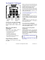
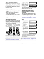
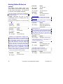
The Chubb AFx™ LCD Keypad
When you enter your user ID and/or PIN, you
will be given access to all menus and features
as assigned through your user authorities.
Keypad Lights
Red Green Yellow
WELCOME
Enter ID:
1
,-#
2
ABC
3
DEF
4
GHI
5
JKL
6
MNO
7
PRS
8
TUV
9
WXY
0
Z_Q
X
Red Flashing:
Protection ON
Solid: Partial
protection
(STAY)
Green On
Always with
power
present.
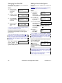
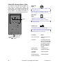
Buttons under the Display Screen
The buttons directly under the display screen
allow selecting associated items on the display
screen. This means the item displayed on the
screen above each button.
Like the rest of the keypad, these buttons are backlit
for use in poor lighting conditions.
X
The Numeric Keypad
The main keypad (in the bottom-left portion of
the unit) provides a convenient way to enter
numbers, and letters as well (when applicable).
Yellow On when
trouble condition
present. Flashing
when there is no
AC mains.
The Chubb AFx LCD (liquid crystal display)
keypad provides an integrated 2-line display
and multi-function backlit keypad.
(The
keypad is hidden behind a hinged access
cover.)
What You can do with the
LCD Keypad
Chubb AFx™ LCD keypads provide
convenient local interface that allows:
a
• Turning protection on and off;
• Checking status of items;
• Controlling / commanding items;
The
Key
This is the "escape" key, which allows you to
return to a previous screen, or exit from a
menu altogether (log out).
The ◄ arrow ► Keys on the Keypad
These keys allow selecting different items and
topics. When available, the left ◄ or right ►
arrow keys will appear on-screen.
Emergency Keys and Programmed
Function Keys
Pressing a number and the ƒ key at the same
time will perform the action as programmed for
that key-sequence. The emergency keys at
the bottom of the keypad each transmit a
specific emergency message (to the central
monitoring station).
• Performing administrative tasks;
• Some models can act as a card reader to
permit access to locked doors.
For more information on the emergency keys, refer
to "Using the Emergency Keys" in the "Alarms…"
chapter.
Keypad Display and Buttons
For details on the programmable function keys, refer
to "Using the Function Keys" in the "Status &
Control" chapter.
The display is your 'window' into the Chubb
AFx system.
2
Chubb AFx™ LCD Keypad User's Guide
500-3650E rev1.3
If You Are Being Forced to Enter
Protected Premises
A duress (panic) alarm is triggered when you
enter your PIN with the last two digits
reversed.
This can be done at reader
keypads, system LCD keypads, and Suite
Security LED keypads.
Normal PIN Example: 1 2 3 4
If being forced to Enter: 1 2 4 3
This feature will be available unless it was disabled
by your service technician when the system was
initially set up.
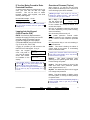
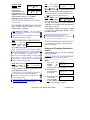
Logging Into the Keypad
(User ID and/or PIN)
NOTE: Your Security Representative /
Installer will supply you with your User ID
and PIN number for pressing into the
keypad and logging in to the system.
(The default Master user ID and PIN is:
e.g. ID: 01 or 001, PIN: 7793)
"Logging In" provides you with access to the
features of the LCD keypad. To log in:
Open the keypad
cover, and press in
your user ID number
and/or PIN number
as indicated on the
display.
Welcome
Enter ID: _ _ _
Your Name Appears
Enter PIN: _ _ _ _
When finished viewing or entering items, you can
use the
key to exit (press multiple times as
needed--until the "login" screen appears).
Tip: You will also be logged out automatically if you
do not press any keys for approximately one (1)
minute.
Overview of Screens (Topics)
When logged in, you will see only the topics
that you have the authority to use. Some or all
of the following topics will be available:
Selecting a Topic: Press the "►" key until your
desired topic appears on-screen. Then press the
key directly under your topic to select it.
Off // Stay // On: Push ► for Menus
↓Stay ↓On
The first screen that
you'll see allows you
to arm or disarm the area(s) as desired, or to
access other topics.
Only two of arm/disarm selections will appear
at a time—depending on the present armingstate of the area(s).
Off: all intrusion protection fully off.
Stay: partial protection. Internal motion
detectors disabled. Only perimeter protection
on. For users to remain inside the protected
area.
On: all protection fully on. No one remaining in
the protected area.
Status: This allows checking the status of
various items in the system, or commanding
items into different states.
Please ignore uncommon status screens that may
show up like “Comms, Modem, Licns”. They are for a
service technician’s purposes.
Bypass:
This allows bypassing faulty
sensor(s) so the system ignores them, and/or
to allow arming the system.
History: This allows viewing a record of the
tasks that users have performed (disarm
areas, bypass sensors, etc.)
My PIN: This allows the person who is logged
in to change their password.
Users: This allows adding or deleting 'users'
from the system, or viewing or editing settings
for specific users.
A "User" is a person who has the authority to login to
system keypads, and/or to gain entry at accesscontrolled doors.
500-3650E rev1.3
Welcome
Alarm
Status
Admin
Reference
3
Test: This allows testing different aspects of
the system.
Verify: This allows a person to prove they are
present. This lets a monitoring facility know
that you are present after accidentally tripping
a sensor, and/or silencing a false alarm.
Schdule: This allows extending the scheduled
closing time for an area (the "work-late"
feature), or suspending a schedule altogether.
Arm/Disarm: Re-enters the screen for turning
the system to Off, Stay or On.
Time: This allows changing the time and/or
date for a system panel.
Keypad Entry Basics
Use the buttons directly under the display
screen when the arrow “È“ beside desired
subjects on the screen is pointing down to the
corresponding keypad buttons.
The ◄ and ► buttons allow you to view
additional topics--when available.
("◄" and/or "►" will appear on the display
screen to indicate these keys can be used).
Use the “ ” escape key when finished with
your present menu / topic to return to the main
screen or back out of inner screens.
Entering Letters (e.g., for a user's name)
The numeric keypad allows entering numbers-and letters as well--for items that support this.
When required, press the specific key multiple
times until the desired letter appears:
Pressing "2" multiple times produces: 2 A B
C on the screen.
Pressing "3" multiple times produces: 3 D E
F on the screen.
...etc. (look for the letters on each key).
Tip: The "_" on the 0 key (zero) represents a space.
4
Chubb AFx™ LCD Keypad User's Guide
500-3650E rev1.3
Alarms, Turning
Protection On
and Off
500-3650E rev1.3
Welcome
Alarm
Status
Admin
Reference
5
Alarm Monitoring Features
Depending on how the system is set up,
specific alarms may be indicated by any of the
following items:
• An alarm message will appear on specific
keypad(s);
• Keypad 'sonalerts' (beepers) may sound;
• A local siren may be triggered;
UL Listed Systems: For UL listed systems, a local
siren must be triggered.
• An alarm message may be transmitted to a
monitoring station (and/or to a management
PC running the Director software);
UL Listed Systems: For UL listed systems, an
alarm message must be transmitted.
• A programmable "output" may be triggered
(this can cause a horn to sound, or perform
any other type of automated 'switching'
function);
• A numeric pager may be called to let the
wearer know that a specific type of alarm has
occurred.
These actions can be fully customized for each type
of event--for each arming level that the system can
be in at any time (Off, Stay or fully ON).
Audible Keypad Tones
• The
following
audible
keypad
tones
accompany keypad visual indications like
lights and screen messages.
• There are 2 versions for some of the tones to
operate:
Standard: regular tone operation.
Alternative: opposite to regular operation.
New systems will use Standard Tone Operation.
Alternative tone operation must be especially
programmed by a security representative.
These tones also apply to the ones emitting
from an Arming Station. See the section on
the Arming Station Reference in this manual.
Pressing Keypad Keys/Buttons
Single short beep
Fire Alarm
Standard and Alternative Operation:
A quick on and off tone.
Burglary Alarm, Trouble Condition
Standard Operation:
Steady continuous tone.
Alternative Operation:
Slow on off tones
Entry and Exit Delay (tones generated when the
protected area is entered or protection is turned on
before leaving)
Standard Operation:
Slow on off tones until the last 15 seconds of
the delay when the tones speed up and become
more immediate to indicate that protection
should be turned off or exiting should be done
to prevent a false alarm.
Alternative Operation:
Continuous tone.
Entry Delay after the System has been in Alarm
or during an Alarm Condition
Standard and Alternative Operation:
Very fast on and off beeps.
Exit Delay with a Protection Point Insecure
Standard and Alternative Operation:
Fast on and off beeps
Confirm Exit Delay (the exit delay is shortened
when the exit door is exited before the end of the exit
delay)
Standard and Alternative Operation:
Fast on and off beeps
Closing Time Soon (a system that has a schedule
will sound a warning when the time for the protection
to turn on is approaching)
Standard and Alternative Operation:
30 minutes before the scheduled protected
area’s protection should turn on, the keypad will
make 3 short beeps. In the final 15 minutes, the
tones will gradually get faster.
Chime (see “Function Key Reference” in this manual)
When the chime feature is turned on and a door
is opened.
Standard and alternative operation:
Three short low sounding beeps.
Error Tones for Wrong Keys Pressed
6 short beeps
6
Chubb AFx™ LCD Keypad User's Guide
500-3650E rev1.3
Steps:
Sirens
1. Enter your user ID
Conventional Siren
Fire Alarm: Intermittent Tone
(the same as a Fire Alarm in the previous
keypad tone details).
Burglar Alarm: Steady Tone.
and/or password to
log into the
keypad.
2. Select Yes to
Silence System?
↓Yes ↓No View↓
silence the alarm.
Voice Siren (optional)
Fire Alarm: Steady tone, followed by
optional voice Fire Alarm Message.
(e.g. “FIRE! FIRE! ... Leave Immediately!”)
Burglar Alarm: On and off tone, followed
by optional voice Burglar Alarm Message.
(e.g. “Intrusion! Intrusion! ... The police have
been called, leave immediately”).
3. Select Yes again
Verify User?
↓Yes ↓No
to verify who you
are.
4. Enter your PIN
To Verify User
Enter PIN: _ _ _ _
when prompted.
This will signal the
monitoring facility that you want to cancel the
false alarm.
5. To disarm area(s),
select "Off".
Dealing with Alarms (what to do if
the keypad is beeping)
If an alarm occurs, you must first decide if it is
a valid alarm (break-in, battery failure, etc.), or
a false alarm. If a valid alarm occurs, be sure
to notify the appropriate persons, and/or take
steps to either deal with the item yourself--if
appropriate, or get yourself and others to
safety.
6. Select Yes to turn
This feature may not be available in all areas.
Consult your local security representative / installer
for more information.
However, fire alarms can not be cancelled.
The following steps assume that you have
accidentally triggered a false alarm. If an
alarm has been generated, the LCD display
will show the alarm, and the keypad 'sounder'
will probably also be making a steady tone.
500-3650E rev1.3
Welcome
Alarm
Push ► for menus
↓Off ↓Stay
All Areas Off?
↓Yes ↓No
all areas off, if
desired.
7. If there was a
false alarm, the
following screen
will appear.
Area XX
Had an Alarm
8. Select Ack to
xxx: Sensor Name
Status
↓Ack
acknowledge the
alarm and disarm
the system.
Silencing a False Alarm
An authorized user can Cancel a false alarm,
disarm the system and inform the monitoring
station not to dispatch the respective
emergency service.
!! In Alarm !!
Enter ID: _ _ _
XXX: refers to the number for the monitored sensor
(input point) that was in alarm.
9. Press this key to
perform another
function.
Disarming...
↓Next Function
To return to the main screen (log out), press
the “ “ escape key a few times, or let the
system time-out (1 minute).
The entry tones will now stop sounding and the
selected areas are now fully disarmed.
If the Verify option is used, it must be done within 1
minute of the false alarm occurring, for the station to
acknowledge the signal.
Status
Admin
Reference
7
Using the Emergency Keys
There are three emergency keys that will
cause an emergency alarm. This will be
transmitted to the monitoring station, and may
also turn on a local alarm, a programmable
output, and/or cause a numeric pager
message to be sent (depending on how the
system is set up).
To transmit an emergency alarm, press the
button on both sides of the specific symbol at
the same time.
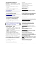
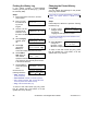
Worklate: Extending the
Scheduled Closing Time
A Schedule represents when e.g. a
commercial system is open for normal
business hours. If the scheduled closing time
is approaching when the protection is turned
on, and you wish to remain in the area, you
can extend the 'closing' time.
Steps:
1. Enter your user ID
and/or PIN to log
into the keypad.
Welcome
Enter ID: _ _ _
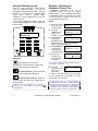
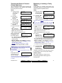
2. Press the
Menu Options
◄ Schdule ► ↓Ok
◄►arrow keys
until you see
"Schdule". Then select Schdule.
WELCOME
Enter ID:
3. Select Schd to
1
,-#
2
ABC
3
DEF
4
GHI
5
JKL
6
MNO
7
PRS
8
TUV
9
WXY
0
Z_Q
AreaName.....Off
change the
↓Schd ↓Next Area
Schedule for the
selected area (e.g. Office) or select Next
Area to select a different area.
4. Select WorkLate
X
X
5.
Alert Keys
Fire, press the “F” function key
(discussed in “Using the Function Keys”) and
the left arrow key ◄ at the same time.
Panic/Police Alarm, press the left and
right arrow keys ◄ ► at the same time.
Emergency (Non medical), press the
right arrow key ► and the “ “ Escape key at
the same time.
Alert Keys are only available if they have been
ordered by you and supplied by your Security
Representative.
8
Close -> 09:30pMo
to change the
↓Worklate Susp↓
closing time for
your selected area.
..until 17:30pFr
Select "+" or "-"
↓Ok
↓+ Adj -↓
to adjust (Adj)
the closing time
as desired.
The "+" and "-" (Adj) keys adjust the closing time by
increments of 30 minutes.
6. Once the
scheduled closing
time is correct,
select Ok.
..Until 17:30pFr
↓Ok
↓+ Adj -↓
To return to the main screen (log out), press
the “ “ escape key a few times, or let the
system time-out (1 minute).
An authorized user may only change the WorkLate
Schedule for the current day. 15 minutes before a
Schedule ends, the system will chime indicating that
a scheduled closing is pending. At this stage, an
authorized user may change the WorkLate time to
suspend the system closing until a specified time.
Chubb AFx™ LCD Keypad User's Guide
500-3650E rev1.3
Suspending Schedules for an
Area or Areas
Turning Protection ON, STAY, or
Viewing the Present Arming-Level
A schedule can be blocked altogether if you do
not want a scheduled closing to occur.
With the appropriate authority, you can arm
and disarm the system, or specific area(s)
using an LCD keypad.
Steps:
1. Enter your user
ID and/or PIN to
log into the
keypad.
2. Press the ► keys
Steps:
Welcome
Enter ID: _ _ _
Menu Options
◄ Schdule ► ↓Ok
until you see
"Schedule". Then
press the key under "Schedule" to select it.
3. Select Schd to
Area..........Off
suspend the
↓Schd ↓Next Area
Schedule for the
selected area (e.g. Office) or select Next
Area to select a different area.
4. Select Susp to
suspend the
Schedule for the
selected area.
Close by 17:30pMo
↓Worklate Susp↓
5. Select Ok to
Suspended
suspend the
↓Ok Resume↓
schedule and
return to the main screen. Select Resume to
reinstate the schedule.
To return to the main screen (log out), press
the “ “ escape key a few times, or let the
system time-out (1 minute).
WARNING: A Schedule will remain
suspended indefinitely until “Resume” is
selected .
1. Enter your user ID
and/or PIN to log
into the keypad.
Welcome
Enter ID: _ _ _
Push ► for menus
↓Stay ↓On
2. Select the button
for your desired
protection level.
If all areas are currently OFF, only STAY and ON are
shown. If STAY is not an authorized function, only
ON will be shown.
The "Stay" arming-level refers to the perimeter
sensors being monitored, but not the interior ones.
This is typically used when someone is inside the
facility or protected area.
3. Select No to
All Areas ON?
choose an Area to
↓Yes ↓No
view or change (or
Yes for all areas ON).
4. Press the left
button to set the
AreaName.....Off
↓On ↓Nxt Done↓
arming-level.
Select Nxt to choose a different area, or
select Done to exit.
5. Select OK to
confirm. (Review
allows you to
change your mind.)
Area(s) to....ON
↓OK
↓Review
6. If points are currently bypassed, in tamper,
in alarm, or not Ok, the following screen will
appear when you are attempting to arm an
area (to Stay or ON).
7. Select Ok? to arm
Pts in Bypass!
the system, or
↓Ok?
↓View
View to list points
that are currently not Ok.
WARNING: Selecting OK will arm the
system with point(s) not secure.
500-3650E rev1.3
Welcome
Alarm
Status
Admin
Reference
9
Select View to view
Points not Ok!
points that are
↓View
currently bypassed or
not Ok. At this time the system will indicate
points that are not OK and force you to either
bypass or secure
AreaName.....Off
these points in order
↓Pts ↓Next All↓
to arm the system.
Select the desired topic:
• Pts: Bypassable points (sensors) in the
displayed area;
• Next: Show the
xxx:► Sensor Name
next area;
Status ↓Bypass ↓?
• All: All bypassable
points regardless of area.
When a point/sensor is displayed, you'll have
these options:
• "◄►": Press the arrow keys to scan through
the sensors (points) in the system (or the
selected area);
• Bypass: Select this
Arming...Bypass
for the system to
↓Next Function
ignore (bypass) the
selected sensor.
• "?" jumps to the next point that is not OK.
Once all points have Area(s) arming
been bypassed or Please Leave
secured, the system will automatically arm.
3. This screen will display, to choose turning
the area fully off Push ► for menus
or put in Stay for ↓Off ↓Stay
partial protection.
4. After making your All Areas Off?
selection, this
↓Yes ↓No
screen will ask if
the protection for all areas should be
changed, if there is more then one area. If
“No” is selected,
Area 1.........On
this screen will
↓Off
↓Nxt Done↓
display the
current condition of the available areas
e.g. “On” and selections for that area.
Selections for other areas are displayed by
pressing ”Nxt” or just change the
protection level for the area you are in.
Pressing the button below “Done” will
process the selections you made.
Turning Protection On by Area
Groups, a Group of Areas or
Individual Areas.
Check with your Security Representative / Installer
to have this feature added to your system. You must
have the proper Authority to control additional
protected areas.
1. Enter your user ID
and/or PIN to log
into the keypad.
After arming (On), leave immediately by the
designated exit route!
2. Select the button
The tone you will hear is a reminder for you to
quickly leave the area or premises. During the
last 15 seconds this intermittent tone will
speed up. The exit tones will now stop
sounding and the selected areas are now fully
armed.
3. Select Yes if an
Turning Protection OFF
1. When you have entered the area with THE
protection ON, the keypad will beep and
the screen will To Disarm
Enter ID: _ _ _
display:
2. Enter your user ID and/or PIN to log into
the keypad.
10
Welcome
Enter ID: _ _ _
Push ► for menus
for your desired
↓Stay ↓On
protection level.
Selecting “Stay” will supply selections for the
areas separately. Selecting “On” will supply
the special way to turn area protection on.
All Areas ON?
authorized user
↓Yes ↓No
has been
assigned with the authority level to turn on a
certain group or groups of areas at the same
time.
4. If authorized,
Choose Area by?
select No to
↓Group ↓Area
choose individual
Area Groups or Areas to turn on.
Chubb AFx™ LCD Keypad User's Guide
500-3650E rev1.3
Area Priority Protection On/Off
Priority Arming requires that areas are armed
and disarmed in order of their priority. If
protection for Area 1 is turned on first, then
area 2 and then 3, disarming the areas would
then require area 3 to be turned off first, then
area 2 and then 1. This sequence can vary
and it is necessary to learn the order from your
Security Representative / Installer or System
Administrator.
• If protection for
AREA 1
areas is not turned
Priority Fail
on, off in their
proper sequence, this error screen will appear
and the process will not occur. It will have to be
repeated properly.
Turning ON an Area’s Protection
using an Access TOKEN
Check with your
Security
Representative /
Installer to have this
feature added to your
system. You must have
the proper Authority to
control additional
protected areas.
1. Place and hold
Welcome
the token in
Enter ID: _ _ _
front of the
keypad within 2 -3 inches (78mm).
2. The exit delay
Arming...
will start and the
↓Next Function
keypad will
sound its exit delay beeps.
Common Area Protection On/Off
A common entrance used by e.g. a user who
has authority for only certain areas in a
multiple area system, must be able to enter the
entrance to reach their areas. At the same
time, a user who only has authority for their
particular areas beyond the same entrance
must also be able to enter. This can make this
main entrance a “common area”. Both users
can have authority for this common area to
reach their particular areas. This allows them
to be able to turn the protection on and off to
this common area when their authorized areas
are in use. Check with your Security
Representative / Installer or System
Administrator for information and authority for
a Common Area.
500-3650E rev1.3
Welcome
Alarm
Turning OFF an Area’s Protection
using an Access TOKEN
1. If you have entered the area with protection
on, the keypad
will beep and
the screen will
display:
To Disarm
Enter ID: _ _ _
2. Repeat holding the token in front of the
keypad within 2 -3 inches (78mm).
3. The screen will
display:
Disarming...
↓Next Function
Protection will be off.
Status
Admin
Reference
11
UK System Operation
The following is required to ensure conformity
with the ACPO, DD243:2002 Standard.
UL Listed Systems: Not to be used for UL listed
systems.
If this screen displays Confirmed Alarm!
after disarming …
Enter ID: _ _ _
the system has had a
Confirmed Alarm and the following procedure
must be done:
Resetting Confirmed Alarms
Once a confirmed alarm occurs at a site, the
user will be able to disarm and silence the
system. The confirmed alarm strobe display, if
it is part of the system’s equipment, will also
turn off. However, arming will be blocked until
reset by an Engineer during a service call in
the following manner:
1. The main panel cabinet must be opened to
activate the ‘tamper sensor’
2. The system will generate a tamper alarm; the
authorized user must first silence this.
3. Next, the Service user ID and Pin must be
entered followed by the ID and Pin of the
authorized user.
(Master end user ID and PIN default: e.g. ID: 01
or 001, PIN: 7793)
4. Select “Reset Confirmed Alarm”.
5. Close the main panel cabinet to secure the
tamper sensor.
If there is an attempt made to arm the system
and this reset procedure has not been done, this
!! Cannot Arm !!
screen will appear
momentarily…
Confirmed Alarm!
External Arming Button
When attempting to arm the system and exiting
the protected area the “external arming button”
must be pressed. Failure to do so will result in a
“Failed to Exit” condition. The protection will
disarm at the end of the arming delay and a failed
to exit report will be logged in the system’s
History log.
12
UK and European System
Operation
UL Listed Systems: Not to be used for UL listed
systems.
Restoring Tampers
Once a tamper condition occurs it will be
logged in the system’s History log. Any
authorized users can silence tampers
Was in Tamper!
Enter ID: _ _ _
however; the following system message will
scroll on the LCD display to indicate that a
tamper condition had occurred…
This message will only appear when the
tamper condition has been restored. The
yellow “trouble” light on the keypad will also
turn off.
1. This message can only be cleared during a
service call in the following manner.
2. The main panel cabinet must be opened to
activate the ‘tamper sensor’
3. The system will generate a tamper alarm; the
authorized user must first silence this.
4. Next, the Service user ID and Pin must be
entered followed by the ID and Pin of the
authorized user.
(Master end user ID and PIN default: e.g. ID: 01
or 001, PIN: 7793)
This screen message
2nd Service User
will display to prompt
Enter ID: _ _ _
for the master
authority user to enter their ID and Pin.
After the reset procedure has been completed,
the system Status can be checked to ensure that
the only tamper condition still displaying is the
open main panel cabinet.
5. Close the main panel cabinet to secure the
tamper sensor.
Arming / Disarming Conditions
If at the time of arming, certain system faults are
present, arming will be blocked.
The red armed light on the keypad will only stay
on for 30 seconds from the time of any arming.
This is to prevent the condition of the system
from being easily visible.
Chubb AFx™ LCD Keypad User's Guide
500-3650E rev1.3
To view the armed state of the system, log in
from the “Enter ID:”
All on
Menus ►
screen. If all areas
↓Off ↓Stay
are ON this screen
will display:
If one or some areas
are armed this screen
will display:
Partially Armed ►
↓Off
↓Stay
If a trouble condition occurred since the last
arming, this screen will display on disarming…
When this screen is
System Fault or
acknowledged (Ack)
Tampered
↓Ack
the problem condition
can only be seen by checking system Status. If
fault conditions are present, than arrangements
should be made to have them corrected.
Remote Reset
For customers who would rather reset the
ACPO alarm themselves, instead of a
service/engineer person attending and doing
it.
• When the ACPO alarm occurs, the LCD
keypad screen will display a 6 digit code.
• The customer notifies the monitoring
station with this number.
• The monitoring station enters the number
in this program’s “Customer Input:” box
and generates a response 6 digit number.
• The monitoring station gives this response
number to the customer who enters it into
the keypad and can reset the ACPO
alarm.
500-3650E rev1.3
Welcome
Alarm
Status
Admin
Reference
13
#
14
Chubb AFx™ LCD Keypad User's Guide
500-3650E rev1.3
Checking Status
and Controlling
Items
500-3650E rev1.3
Welcome
Alarm
Status
Admin
Reference
15
Status and Control Features
NOTE: Status will display certain options e.g.
“Comms, Modem, Licns” that will not appear
familiar because they are not covered in this
publication. These options should be ignored
by the end user because they are for a
technician’s use only.
Using an LCD keypad, you can:
• Check the status of various items in the system
and view the present arming-level of desired
area(s).
• Bypass faulty sensors to allow arming the
system and/or specific area(s);
• Command doors to Unlock, relock, or change
operating characteristics;
• Use the function keys to perform preprogrammed signalling and/or switching
functions.
Using the Function Keys
Welcome
Enter ID: _ _ _
Your Name Appears
Enter PIN: _ _ _ _
Then press and hold the “F” key, and press the
desired number at the same time.
Checking the System Status
(monitored conditions for a system
control unit)
The system status feature shows the status of
all conditions such as (tamper, low battery,
etc.) that are being monitored for the control
unit associated with your keypad.
These items may also be referred to as "Equipment"
conditions.
Steps:
LCD keypads provide 10 function keys that
can perform various signalling and/or switching
functions. Consult with your security
representative / installer to learn what the
ones you may have ordered do.
To use function key 1, 2, 3, 4, or 5, simply
press and hold the “F” key, and press the
desired number at the same time.
,
1 -#
2 ABC
3 DEF
4
GHI
5
JKL
6
MNO
7
PRS
8
TUV
9
WXY
0
Z_Q
X
X
For function keys 6, 7, 8, 9, and 0, a user with
function-key authority may need to enter their
ID/PIN numbers to be allowed to use these
function keys.
This requirement can be assigned as necessary to
any areas. Check with your security representative.
16
To log in, open the
keypad cover, and
key in your user ID
number and/or PIN
number as indicated
on the display.
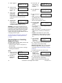
1. Enter your user ID
and/or PIN to log
into the keypad.
2. Select ► to
access other
functions.
Welcome
Enter ID: _ _ _
Push ► for menus
↓Stay ↓On
3. Use the ◄ and ►
Menu Options
◄ Status ► ↓Ok
arrow buttons to
scan through the
listed items. When ”Status" appears, press
Ok.
4. Use the ◄ and ►
Status Options
arrow buttons to
◄ System ► ↓Ok
scan through the
listed items and press Ok.
To return to the main screen (log out), press the
“ “ escape key a few times, or let the system
time-out (1 minute).
For details on the possible status messages, refer to
"Error Messages and Trouble Indications" in the
reference section near the back of this guide.
Chubb AFx™ LCD Keypad User's Guide
500-3650E rev1.3
Checking the Status of Sensors
(Points) and Areas
Bypassing or Isolating a Faulty
Sensor
The Points-status feature allows checking the
status of sensors in the system (and viewing
the arming-level for areas).
Steps:
If the system (or a specific area) needs to be
armed with a faulty or insecure sensor, you will
need to bypass the problem sensor.
Steps:
1. Enter your user
1. Enter your user ID
ID and/or PIN to
log into the
keypad.
2. Select ► to
access other
functions.
3. Use the ◄ ►
arrow buttons to
scroll the items
4. Select Points
press Ok.
Welcome
Enter ID: _ _ _
Push ► for menus
↓Stay ↓On
Menu Options
◄ Status ► ↓Ok
Status Options
◄ Points ► ↓Ok
5. Select the desired
AreaName.....Off
topic:
↓Pts ↓Next All↓
• Pts: Protection
Points (sensors) in the displayed area;
• Next: Show the next area;
• All: All points regardless of area.
When a point/sensor
xxx: Sensor Name
is displayed, you'll
Status ↓Bypass ↓?
have these options:
• "►": Press the right arrow key to scan through
the sensors (points) in the system (or the
selected area);
• Bypass / Delbyp: Select Bypass to have the
system ignore the sensor (or "Delbyp" to remove
a "Bypass" that is in effect).
Also see: Bypassing a faulty sensor, to follow.
• "?" jumps to the next point that is not OK.
Bypass appears only for points that are bypassable.
An Entrance Door must be specially programmed
to be bypassable. Ask your Security
Representative.
An area’s sensor cannot be bypassed if the area is
ON.
If all points are OK,
you will see an "All
Secure" message.
All points in
area are secure
To return to the main screen (log out), press the “ “
escape key a few times, or let the system time-out
(1 minute).
500-3650E rev1.3
Welcome
Alarm
and/or PIN to log
into the keypad.
Welcome
Enter ID: _ _ _
2. Scroll the ◄ ►
Menu Options
◄ Bypass ► ↓Ok
left and right
arrow keys until
“Bypass” appears on the display. Press Ok
An area’s sensor cannot be bypassed if the area is
ON.
You can also bypass sensors through the Pointsstatus screens (see the preceding topic for details).
3. Select the desired
AreaName.....Off
topic:
↓Pts ↓Next All↓
• Pts: Bypassable
points (sensors) in the displayed area;
• Next: Show the next area;
• All: All bypassable points in all areas.
4. When a
xxx: Sensor Name
point/sensor is
Status ↓Bypass ↓?
displayed, you'll
have these options:
• "►": Press this key to scan through the sensors
(points) in the system (or the selected area);
• Bypass / Delbyp: Select Bypass to have the
system ignore the sensor (or "Delbyp" to remove
a "Bypass" that is in effect).
• "?" jumps to the next point that is not OK.
No bypassable
points are secure, points insecure
you will see a
related message.
5. If all bypassable
A bypass is lifted the next time the area is turned
off, provided the user has the proper authority.
Isolate a Sensor
With “Isolate” authority, a sensor can be
permanently bypassed until the bypass is
manually lifted.
Status
Admin
Reference
17
1. Select Bypass.
2. Select an area
and “Pts” to view
Points in that
area.
Menu Options
◄ Bypass ► ↓Ok
Office........Off
↓Pts
3. Use the ◄ ► left
and right arrow
buttons to scroll
the items
4. Select Doors and
press Ok.
Menu Options
◄ Status ► ↓Ok
Status Options
◄ Doors ► ↓Ok
3. Select “Cmd”,
002►LOBBY MOTION
(Command).
Ok
↓Cmd
?↓
Pressing the
button under the question mark will indicate
bypassable points in the area that are
insecure.
4. Use the arrow
002►LOBBY MOTION
◄►
↓Isolate
keys to do a
regular Bypass
or Isolate the point. Follow the same
procedure to delete “Isolate” for a point.
WARNING: The keypad will indicate there is a
point in Bypass or “Isolate” every time protection
is turned on. A point in “Isolate” will never supply
protection and the “Isolate” will not be removed
the next time the area is turned off. A point in
“Isolate” must have its Isolate deleted in order for
it to supply protection again.
To return to the main screen (log out), press the “ “
escape key a few times, or let the system time-out
(1 minute).
5. Select the desired
•
•
•
AreaName.....Off
topic:
↓Door ↓Next All↓
Door: For doors in
the displayed area;
Next: Show the next area;
All: All doors regardless of area.
6. Now select Door,
•
•
•
D0x: Door Name
or Readers, as
↓Door ↓Readers
desired:
"►": Press this key to scan through the doors
in the system
(or the selected area);
Door: Door status, or commands to unlock or
relock the door, or lockout (or reinstate) all
cards;
Readers: Will indicate the current reader
conditions in the system and lets you change
the condition (e.g., Card+PIN, dual custody,
etc.).
7. If you selected
Checking Status or Controlling
Readers or Doors
The Door status screens allow persons with
the appropriate authority to:
• Check the status of doors in the system (or
specific areas);
• Command doors to unlock, relock, or change
operating characteristics.
Steps:
1. Enter your user ID
and/or PIN to log
into the keypad.
2. Select ► to
access other
functions.
18
Welcome
Enter ID: _ _ _
Push ► for menus
↓Stay ↓On
D0x: Door Name
Door, the door
↓DoorState
?↓
state will be
shown, and you'll have these options:
• "►": Press this key to scan through the doors
in the system (or the selected area);
• Select the door state: Then, you can use the
◄ ► left and right arrow buttons to access a
command (and press the key under the command
to select it);
• "?" jumps to the next door that is not OK.
8. If you selected
D0x: Area Name
Readers, the
↓Cmd
RdrModes
reader mode will
be shown, and you'll have these options:
• "►": Press this key to view the second reader
for the selected door (if applicable);
• Cmd: Provides access to the reader mode
Chubb AFx™ LCD Keypad User's Guide
500-3650E rev1.3
selections that follow.
9. Your Cmd
R0x: Area Name
choices are
↓Mode ↓Card ↓Lock
shown below:
• Mode: Access modes including "Normal",
"Dual Custody" (two users/access cards
needed to enter), and "Escort" (a user
identified as a "Escort" must present their card
first, then a 2nd person with a valid card);
• Card: This includes various card-mode
selections (i.e., card and/or UID and PIN);
• Lock: This allows you to lockout or reinstate
card-access at this reader.
To return to the main screen (log out), press the “ “
escape key a few times, or let the system time-out
(1 minute).
Checking the Status or Controlling
an Elevator Reader
Checking the Status of an
Application Module (POD)
You can check the status of any "application"
modules in the system.
(An application
module provides increased functionality such
as Printer capability.)
POD (definition): "Module" - a controller that e.g.
connects a Printer to the system.
Steps:
1. Enter your user ID
and/or PIN to log
into the keypad.
For systems that include elevators, the
"Status" menus will include an "Elev" selection
for elevators and their associated readers.
The available selections will be the same as
for standard readers, as described in the
preceding section.
Attention:
All floor status and control
functions are available only through the
Director software. It is recommended that all
elevator reader status and control tasks be
performed through the software as well.
Exception: Checking a specific aspect of an
elevator reader can be performed through the
keypad (such as checking if it is in Card Plus
PIN mode), but you will have to log in at a
Director software PC to see if the floors are
secure.
Push ► for menus
↓Stay ↓On
2. Select ► to
access other
functions.
3. Use the ◄ ► left
Menu Options
◄ Status ►
↓Ok
and right arrow
buttons to scroll
the items.
UL Listed Systems: Not evaluated to UL104 –
Elevator Door Locking Devices and Contacts.
Welcome
Enter ID: _ _ _
4. Select App to
view status of an
Application
Module. Press Ok.
Status Options
◄ App ►
↓Ok
ModuleName/Type ►
view the status of
↓Yes ↓No
the indicated
module (e.g. “HSC” for Printer), or use the ►
right arrow button to select another module.
5. Select Yes to
6. Select HSC and
Pod Status . . . .
↓Printer
then Printer to
view the status of
the Printer.
7. The status screen
PRN(printer):OK
POD:OK
will indicate if the
system device is
Ok or disabled and any device related
information.
Select Next to view status of the next module.
To return to the main screen (log out), press the “ “
escape key a few times, or let the system time-out
(1 minute).
500-3650E rev1.3
Welcome
Alarm
Status
Admin
Reference
19
#
20
Chubb AFx™ LCD Keypad User's Guide
500-3650E rev1.3
Administration
and Maintenance
Tasks
500-3650E rev1.3
Welcome
Alarm
Status
Admin
Reference
21
Changing Your Own PIN
Adding a User to the System
The person who is logged in can change their
PIN number at any time.
New users can be added to the system as
needed.
A User is a person who can use system keypads,
and/or gain entry at access-controlled doors.
Steps:
1. Enter your user
ID and/or PIN to
log into the
keypad.
2. Press ► to scroll
to the PIN option.
3. Select My PIN to
change your PIN.
Press Ok
Welcome
Enter ID: _ _ _
Steps:
1. Log into the
Push ► for menus
↓Stay ↓On
Menu Options
◄ My Pin ►
Welcome
keypad by
Enter ID: _ _ _
entering your
user ID and/or PIN as indicated on-screen.
2. Press ► until
↓Ok
"Users" appears,
& press Ok.
Menu Options
◄ Users ►
↓Ok
3. Enter an available
4. Enter your new 4digit or 5-digit
PIN.
New PIN _ _ _ _
For User: UID#
TIP: You can use the letters on the keypad to 'spell'
a word as a reminder of your PIN.
Re-enter the new PIN a second time when
prompted for this (this helps to protect against
typing errors).
Note: The last two digits of the PIN can not be
identical. Do not use consecutive numbers such as
1234. For security reasons, duplicate PINs are not
allowed on systems with a PIN only user code. If the
message “PIN not allowed” appears, select a
different PIN.
PIN Changed
The “PIN changed”
screen displays and
then returns to the
system standby screen.
0xx
user number (and ↓OK Select User
select Ok), or
select Ok, and then press ► until a user
number appears with "Add" (instead of Edit
and Delete).
4. Undfnd
(Undefined)
Select Add.
0xx ►
↓Add
Undfnd
?: In this screen, "?" refers to systems with Suite
Security keypads (allows viewing the user’s Suite
related abilities for the selected user number). Note:
Suite Security assignments for a user are set up
through the Director software.
Refer to the details that follow while working with
any of the listed topics:
Aut: Use the Next
0xx AuthProfile
and Prev(ious)
↓Ok ↓Next ↓Prev
buttons to select an
authority profile for the user. (Select Ok when
finished).
This determines what doors the user can enter (and
at what time of day), and the tasks they will be able
to perform at system keypads. This selection cannot
be Undfnd (Undefined).
Consult your Security Representative / Installer to
make changes to the authority levels.
22
Chubb AFx™ LCD Keypad User's Guide
500-3650E rev1.3
Bypass
Auto-lift Bypass
Test
Service Test
Silence Alarm
Status
History
Function Key Authorization
Work Late
Suspend Schedule
On
Off
Stay
Auto Disarm to Off
Auto Disarm all Areas
Access
Access when Area is
Off/On/Stay
Employee
9
9
9
9
9
9
9
9
9
9
9
9
9
9
9
9
9
9
9
9
9
9
9
9
9
9
9
9
9
9
9
9
9
9
9
9
9
9
9
9
9
9
9
9
9
9
9
9
9
9
9
9
9
9
9
9
9
9
9
9
9
9
9
9
9
Status
Admin
9
9
9
Escort
9
9
9
9
9
9
Master Override
Reset Door Alarm
Door Command
Class A
Class B
Class C
500-3650E rev1.3
Cleaner
Isolate
Worker
Emergency Off
Supervisor
Intrusion
Master
Default Authority Settings
Welcome
Alarm
Reference
23
System / Suite
0xx UserName
(Condo): For
↓System ↓Condo
systems with
0xx AuthProfile
Suite Security
keypads, this screen
↓Ok ↓Next ↓Prev
allows accessing the
System authority screen (same as the
previous Aut “Authority”) or, the Suite
Security (Condo) authority screen.
Tip: Press the “
use this screen.
“ escape key if you do not want to
Use the Next and Prev buttons to select a
Suite Security authority profile for the user.
(Select Ok when finished).
Suite Authority of "Undfnd": This is a reserved
suite user (that can be edited by a user with Suite
"Master" authority).
Suite Security Authority assignments for a user are
set up through the Director software.
More: Provides access to additional screens.
. . . .
Use the
Name:
keypad to enter the ↓OK
user's name, and
select Ok when finished.
Tip: Check the letters on the numeric keypad.
Then, for each letter of the name, press the specific
key until the letter appears (e.g., pressing 2 makes a
2, A, B, C; 0 provides 0, Z, _ <space>, Q, etc).
To move to the next letter-position, use the ► right
arrow button, or wait 2 seconds. To retype a
previous letter, use the ◄ ► left or right arrow keys,
and then enter the letter as before.
Card: Enter the card 0xx UserName
version number (if ↓OK vv_nnnnnnnnn
applicable), and the
access-card/token number for this user, and
select Ok when finished.
If card-access (entry at controlled doors) does not
apply, leave the card number as "000000000".
Card Version number support is supplied by your
Security Representative.
Firmware revisions needed for 9-digit card IDs, or
cards with version numbers: Panel firmware ≥ V3.2,
and door/elevator controller firmware ≥ V1.5.
24
PIN:
This allows New PIN - - - 0xx
setting or changing For User
ID
the
Personal
Number for this user. (You'll be asked to enter
it twice--to help protect against typing errors.)
The last two digits of the PIN must be different. Also,
do not use consecutive numbers like 1234.
Lang / Chal: This 0xx..Lng:Eng.C:N
screen allows setting ↓OK ↓Lang ↓Chal
the LCD language for
this user, and whether or not the "physicallychallenged" unlock times and door-held-open
times apply to this user.
Select Lang to 'toggle' the language, or Chal
to 'toggle' the "Challenged" setting. When
finished, select Ok.
Watch the screen for the settings to change.
(You will remain in this same screen.)
Lng:Eng means Language is English
C:N means Challanged? – No.
To return to the main screen (log out), press the
“ “ escape key a few times, or let the system
time-out (1 minute).
Viewing or Changing Settings for
a User
For an existing user, you can view or edit their
settings as desired.
A User is a person who can use system keypads,
and/or gain entry at access-controlled doors.
Steps:
1. Log into the Welcome
keypad
by Enter ID: _ _ _
entering
your
user ID and/or PIN as indicated on-screen.
2. Press ► until
"Users" appears,
& press Ok.
Menu Options
◄ Users ►
↓Ok
3. Enter the specific
0xx Select User
user number
↓OK
(and select Ok),
or select Ok first, and then press ► until the
desired user appears on-screen.
Chubb AFx™ LCD Keypad User's Guide
500-3650E rev1.3
4. Select Edit.
0xx ► UserName
↓Edit ↓Delete ↓?
↓?: refers to systems with Suite Security (Condo)
keypads (allows viewing the suite user assignments
for your selected user number). Note: Suite user
assignments can only be set up through the Director
software.
Refer to the details that follow while working with
any of the listed topics:
More: Provides access to additional screens.
Card: Enter the card 0xx UserName
version number (if ↓OK vv_nnnnnnnnn
applicable), and the
access-card/token number for this user, and
select Ok when finished.
If card-access (entry at controlled doors) does not
apply, leave the card number as "000000000".
Card Version number support is supplied by your
Security Representative.
Firmware revisions needed for 9-digit card IDs, or
cards with version numbers: Panel firmware ≥ V3.2,
and door/elevator controller firmware ≥ V1.5.
This allows New PIN - - - PIN:
0xx
setting or changing For User
ID
the
Personal
Number for this user. (You'll be asked to enter
it twice--to help protect against typing errors.)
The last two digits of the PIN must be different. Also,
do not use consecutive numbers like “1234”.
Name:
Use the UserName . . . .
keypad to enter the
↓OK
user's name, and
select Ok when finished.
Tip: Check the letters on the numeric keypad.
Then, for each letter of the name, press the specific
key until the letter appears (e.g., pressing 2 makes a
2, A, B, C; 0 provides 0, Z, _ <space>, Q, etc).
To move to the next letter-position, use the ► key, or
wait 2 seconds. To retype a previous letter, use the
◄ ► keys, and then enter the letter as before.
This determines what doors the user can enter (and
at what time of day), and the tasks they will be able
to perform at system keypads.
Setting this as Undfnd will delete the user!
User authority profiles themselves are normally set
up by your service technician (service PIN needed).
System
0xx UserName
↓System ↓Condo
/ Condo (Suite
Security): For
0xx AuthProfile
systems with suite
security keypads, this ↓Ok ↓Next ↓Prev
screen allows
accessing the System authority screen (same
as Aut, above), and the Condo (Suite
Security) authority screen.
Tip: Press “ “ escape key if you do not want to
use this screen.
Use the Next and Prev buttons to select an
authority profile for the user. (Select Ok when
completed).
Condo (Suite Security) Authority of "Undfnd":
This is a reserved suite user (that can be edited by a
user with suite "Master" authority).
Suite Security Authority assignments for a user are
set up through the Director software.
Lang / Chal: This 0xx..Lng:Eng.C:N
screen allows setting ↓OK ↓Lang ↓Chal
the LCD language for
this user, and whether or not the "physicallychallenged" unlock times and door-held-open
times apply to this user.
Select Lang to 'toggle' the language, or Chal
to 'toggle' the "Challenged" setting. When
finished, select Ok.
Watch the screen for the settings to change.
(You will remain in this same screen.)
To return to the main screen (log out), press the
“ “ escape key a few times, or let the system
time-out (1 minute).
Aut: Use the Next 0xx AuthProfile
and Prev buttons to ↓Ok ↓Next ↓Prev
select an authority
profile for the user. (Select Ok when finished).
500-3650E rev1.3
Welcome
Alarm
Status
Admin
Reference
25
Deleting a User
Setting the Date and Time
Users can be deleted from the system when
necessary.
The panel date and time can be set through an
LCD keypad if necessary.
To allow tracking card-usage, you can alternatively
leave the user in the system, but set them to an
authority profile that provides no access to doors or
keypads. (See the preceding topic for more info.)
"Service Test" authority is required to set the date
and/or time.
Note: Setting the authority to "undefined" will delete
the user (equivalent to selecting Delete).
Steps:
1. Log into the
Steps:
Welcome
Enter ID: _ _ _
keypad by
entering your
user ID and/or PIN as indicated on-screen.
2. Use the ◄ ► left
Menu Options
and right arrow
◄ Users ►
↓Ok
buttons to scroll
the items until "Users" appears and press
Ok.
3. Enter the specific
0xx Select User
user number (and ↓OK
select Ok), or
select Ok first, and then press ► until the
desired user appears on-screen.
4. With the desired
user on-screen,
select Delete.
5. Then, select Yes
to delete the user,
or Cancel to stop
the action.
0xx ► UserName
↓Edit ↓Delete ↓?
Del?
↓Yes
↓Cancel
To return to the main screen (log out), press the
“ “ escape key a few times, or let the system
time-out (1 minute).
26
For a reference of the dates to automatically switch
between standard time and daylight-savings time,
refer to "Holidays and Time-Change Dates" (in the
Reference section).
1. Enter your user
ID and/or PIN to
log into the
keypad.
Welcome
Enter ID: _ _ _
2. Use the ◄ ► left
Menu Options
and right arrow
◄ Time ►
↓Ok
buttons to scroll
the items until "Time" appears and press Ok.
3. Enter the current
Date and Time.
Date
Time
YY-MM-DD
HH:MM ↓Ok
4. Watch the flashing cursor as you enter the
year, month, day, hours, and minutes (2
digits each).
When finished, select Ok.
NOTE: Enter the hours as 00-23 (24-hr. clock).
Example: Noon = 12:00, 1PM = 13:00, 2 PM = 14:00
to 11PM = 23:00, Midnight = 00:00, 1 AM = 01:00, 2
AM = 02:00 etc.
You can use the (◄ ►) keys to scroll back or
forward within the date or time as needed.
To return to the main screen (log out), press
the “ “ escape key a few times, or let the
system time-out (1 minute).
Chubb AFx™ LCD Keypad User's Guide
500-3650E rev1.3
Manually calling the Director PC
from the LCD Keypad:
• This operation is for systems that can
communicate with the Director software.
• If the system configurations have been
changed example: by the customer to add a
new user, it will be necessary to update the
Director configurations for the system.
Steps:
1. Enter your user ID
and/or PIN to log
into the keypad.
2. Use the ◄ ► left
3. Select All for a
View History of:
◄ All
► ↓Ok
complete list, or
Category for
history referring to an Area, Condo (Suite
Security) keypad, or Application module
(e.g., Printer). Press Ok.
2. Push the arrow keys for Menu Selections.
3. Use the ◄ ► left
4.
Menu Options
◄ Director ► ↓Ok
and right arrow
buttons to scroll
the items until Director appears and press
Ok.
Director Options
“Director
Options”, “Update ◄ Update Cfg ► ↓Ok
Config” will
display. Press Ok.
5. “Updating Config,
Please Wait” will
appear and then
change to
“Connecting”
Menu Options
◄ History ►
↓Ok
and right arrow
buttons to scroll
the items until History appears and press
Ok.
1. Enter your user ID and/or PIN to log into the
keypad.
Welcome
Enter ID: _ _ _
Updating Config
Please wait......
4. If you selected
Category, select
your desired topic
(such as by Area).
5. If you selected by
AreaName.....Off
Area, the arming↓Hist ↓Next Area
level for the first
area will be shown, and you can select:
• Hist: Shows the log of events for the
displayed area;
• Next Area: Jumps to the next area.
6. When the system
xxx ► 1:23pMar
the History press
Event Displays ...↓
the (◄►) right or
left arrow keys. For more details about this
event select ". . .↓ ".
6. To cycle through
7. An asterisk: “
” will appear between the
hour and the minute display on the time and
date main screen until the communication is
complete.
(Condo: Suite Security)
If you selected "All" the area or other item associated
with each event will be shown on the screen.
Updating Config
Connecting......
Download Config
is communicating
In Progress.... –
with the Director
software, “In
Progress” will appear with a rotating bar next
to it.
View History of:
↓Area ↓Condo ↓App
Press any of these keys to continue viewing the
History.
"T / L" next to the time indicates that the date/time
had not been set when the event occurred.
Viewing the History
All activity that occurs in the system can be
viewed one event at a time. This includes area
(alarms) /door activity, as well as the tasks that
users have performed at a keypad.
To return to the main screen (log out), press
the “ “ escape key a few times, or let the
system time-out (1 minute).
Depending on your system type and licensing
permissions, up to 65 536 events will be recorded.
Viewing an area's history requires authority for that
area.
500-3650E rev1.3
Welcome
Alarm
Status
Admin
Reference
27
Printing the History Log
If your system includes a printer-capable
module, you can print the history log. (This will
be sorted by date).
Steps:
1. Ensure the printer is turned on, and has
paper loaded.
2. Enter your user
ID and/or PIN to
log into the
keypad.
3. Use the ◄ ► left
Welcome
Enter ID: _ _ _
Menu Options
◄ History ►
and right arrow
↓Ok
buttons to scroll
the items until History appears and press
Ok.
4. When Category
appears, press
Ok.
View History of:
◄ Category ► ↓Ok
5. Select App
View History of:
(Application
↓Area ↓Condo ↓App
Module) to
access the module with printer functions.
6. Select SMA or
Menu Option
HSC which are
↓SMA
↓HSC
other related
equipment selections for use by a technician
only. However, they will both permit access
to the Printer selection.
7. Select Printer to
access the printer
menu.
Choose from the
following selections:
Changing the Printed History
Language
You can change the language for the printed
history log when needed.
Check with you Security Representative / Installer to
confirm your system version is capable of this
feature.
Steps:
Follow steps 1 to 6 from the previous “Printing
the History Log”
7. At step 7, select
Select Option...
Lang to change
↓Printer ↓Lang
the printing
language for this application module.
The present printed language will be indicated on the
first line next to "Lang:”.
8. Select Change to
Lang: Language
change the
↓Ok ↓Change
language. Press
Ok when completed.
To return to the main screen (log out), press
the “ “ escape key a few times, or let the
system time-out (1 minute).
Select Option...
↓Printer ↓Lang
Printer On-Line
↓Pause ↓Cnc ↓Plog
• Start: Enables the
printer (if required).
• Pause / Resume: Pauses or resumes a printout;
• Cnc: Cancels a printout. Tip: You may also need
to turn the printer off to clear its memory.
• Plog: Prints the entire history log.
To return to the main screen (log out), press
the “ “ escape key a few times, or let the
system time-out (1 minute).
28
Chubb AFx™ LCD Keypad User's Guide
500-3650E rev1.3
NOTE: If any fire sensors or 24 hour type inputs
must be tested and it is a reporting system, the
monitoring station must be notified.
Testing Monitored Sensors
(Performing a Walk Test)
A Walk Test allows you to test specific
sensors (protection points) in the system, to
ensure that they are functioning properly.
A walk test can be done by users with "System Test"
authority.
A walk test must be completed within 15 minutes.
Emergency points (i.e. smoke, fire alarm, panic, etc.)
on a Monitored system, display as Armed and should
not be tested during a Walk Test. The monitoring
station must be notified if these points will be tested.
UL Listed Systems: Fire sensors must be tested
once per week for UL listed systems.
When tested successfully, Emergency points will
indicate PASS and Armed will change to Alarm.
"Pass" indicates that an intrusion point is functioning
correctly (i.e. the sensor is operating properly), while
"Fail" indicates that a problem may exist with that
point or that the point was not tripped.
All points except Emergency points may be
bypassed during the Review for convenience.
Restore any bypassed points before turning
protection on or they will reduces system security.
The walk test must be completed within 15 minutes.
7. After activating
Area in walk test
points in the tested ↓Review ↓End
area, return to the
keypad and select Review to view the results
of the Walk Test.
8. The tested points
and the results
(Pass/Fail) will be
displayed.
xxx ►
Status
ItemName
...↓
9. Press the ". . .↓ " key to view all points that
passed during the test. Another method is to
use the ◄ ► left and right arrow buttons to
scroll through the results of all points tested in
the area.
To return to the main screen (log out), press the
“ “ escape key a few times, or let the system
time-out (1 minute).
Steps:
1. Enter your user ID
and/or PIN to log
into the keypad.
Welcome
Enter ID: _ _ _
2. Use the ◄ ► left
Menu Options
◄ Test
► ↓Ok
and right arrow
buttons to scroll
the items until Test appears and press Ok.
3. When Area
appears, press Ok.
Test?
↓Area
↓System
4. Choose from the following selections:
•
•
Test: To test the
AreaName.....Off
displayed area;
↓Test ↓Next Area
Next Area: To
jump to the next area.
5. Select Walk to
perform a Walk
Test of this area.
Select test type
↓Walk ↓Holdup
6. At this time you can proceed to test the
protection points in the selected area (i.e.
open doors, walk in front of motion detectors,
etc.).
500-3650E rev1.3
Welcome
Alarm
Status
Admin
Reference
29
Testing Panic Buttons
(Performing a Hold-up Test)
UL Listed Systems: Not evaluated to UL636 –
Holdup Alarm Units and Systems.
A Hold-up Test allows you to test "hold-up /
panic” devices in the system, to ensure they
are functioning correctly.
NOTE: Using the Hold-up test selection will
prevent hold-up signals from being transmitted to
the monitoring station.
A hold-up test can be done by users with "System
Test" authority.
Steps:
1. Enter your user ID
Welcome
Enter ID: _ _ _
and/or PIN to log
into the keypad.
2. Use the ◄ ► left
Menu Options
and right arrow
◄ Test
► ↓Ok
buttons to scroll
the items until Test appears and press Ok.
3. Select Area.
Test?
↓Area
↓System
4. Choose from the
AreaName.....Off
following
↓Test ↓Next Area
selections:
• Test: To test the displayed area;
• Next Area: To jump to the next area.
Select test type
5. Select Hold-up to
perform a 'hold-up' ↓Walk ↓Holdup
test of this area.
At this time you can proceed to Test the Holdup devices in the selected area. Like press in
panic buttons, etc.
NOTE: Using the Hold-up test selection will
prevent hold-up signals from being transmitted
to the monitoring station.
When activating hold-up devices in the tested area,
the system will emit a chime when the hold-up points
are activated, if functioning correctly. If no chime is
emitted when testing the points, you may need to
inquire about it with your Security Representative.
6. Select End when
finished viewing
and/or to select
another area to test.
30
Trip holdup pts!
↓End
To return to the main screen (log out), press
the “ “ escape key a few times, or let the
system time-out (1 minute).
Testing Sirens (System Test)
Test Your System Once a Week
Weekly testing of the system’s siren/bell is
required. A System Test allows you to test
the entire system to ensure security
components are functioning properly. This
test will turn on the keypad’s lights,
sounder and the system’s siren for 5
seconds to make sure their all okay.
Should any part of the system appear not to
be working correctly, notify your Security
Representative / Installer immediately for
assistance.
UL Listed Systems: This test must be performed
once per week for UL listed systems.
Steps:
1. Enter your user
ID and/or PIN to
log into the
keypad.
Welcome
Enter ID: _ _ _
2. Use the ◄ ► left
Menu Options
◄ Test
► ↓Ok
and right arrow
buttons to scroll
the items until Test appears and press Ok.
3. Select System.
Test?
↓Area
↓System
All Sirens will sound for 5 seconds and all keypad
lights will turn on to indicate that the system is
functioning correctly.
4. During the system
test, this message
will appear.
System Testing
ChxSum [xxxxx]
Please ignore this ChxSum message. It is for
technical personnel use.
To return to the main screen (log out), press
the “ “ escape key a few times, or let the
system time-out (1 minute).
Chubb AFx™ LCD Keypad User's Guide
500-3650E rev1.3
Reference
Topics
500-3650E rev1.3
Welcome
Alarm
Status
Admin
Reference
31
System Information
Your alarm system has specific information. This information should be recorded below at the time
of your system’s installation.
Protected Area Names:
Contact Information
Area 1: _____________________________
Security Representative:
___________________________________
Area 2: _____________________________
___________________________________
Area 3: _____________________________
___________________________________
Area 4: _____________________________
Monitoring Station Phone Number:
Area 5: _____________________________
___________________________________
Area 6: _____________________________
Area 7: _____________________________
Your System Number:
___________________________________
Area 8: _____________________________
Area 9: _____________________________
When to Contact the Monitoring Station
• When an accidental alarm happens.
• When major work is being done on the
premises that could interfere with the alarm.
• If you loose your system number and
password.
• When doing a periodic test that may involve
testing panic buttons, some sensors or with all
the protection turned on.
Area 10:_____________________________
Area 11:_____________________________
Area 12:_____________________________
Area 13:_____________________________
Area 14:_____________________________
When to Contact your Security
Representative
• If there appears to be a fault with the system.
• To order additional protection equipment for
Area 15:_____________________________
Area 16:_____________________________
installation. Like, a contact for a new door,
smoke sensors, motion detector for a new
room addition etc.
32
Chubb AFx™ LCD Keypad User's Guide
500-3650E rev1.3
System Details:
Function Key Reference
Entry and Exit Delays:
The Function key ( F ) is pressed and held in
while pressing specific number keys for
customized functions.
Entry Delay:_______
Exit Delay:_______
Note: Function keys are not active until they have
been added to the system by your Security
Representative.
Miscellaneous Features:
Yes
No
Duress PIN entry supported
Entry Delay in Stay
Function keys 1 – 5 can be used by anyone.
Function keys 6, 7, 8, 9 and 0 may require a
user (with function key authority) to enter their
user numbers before they can operate the
function keys.
Arm to Stay if Failure to Exit
Function Key Assignments:
Terminate Exit Delay
F + 1 = _________________________
Alarm if Failure to Exit
F + 2 = _________________________
F + 3 = _________________________
F + 4 = _________________________
Emergency Keys that are Available:
Yes
No
Fire
Police
Emergency (non medical)
F + 5 = _________________________
(also turns "chime" on and off)
F + 6 = _________________________
F + 7 = _________________________
F + 8 = _________________________
F + 9 = _________________________
F + 0 = _________________________
Door Chime Feature:
The "Door Chime" feature refers to LCD
keypads emitting tones when a perimeter door
is opened to alert the person(s) inside that
someone has entered. This feature can be
used when the system is turned off or while it
is in perimeter protection (doors only) referred
to as "Stay". The system has to be
programmed for “Allow User Entry at the Front
Door in Stay“ by the installer.
Pressing keypad keys F and 5 simultaneously
always toggles the "Chime" feature on and off.
This function key sequence can also be
programmed for an additional function that can
turn on or off, when the chime is turned on or
off.
500-3650E rev1.3
Welcome
Alarm
Status
Admin
Reference
33
Residential Fire Safety / Evacuation Plan
No fire detection system should be considered
100 percent foolproof.
This fire alarm system can provide early
warning of a developing fire. Such a system,
however, does not ensure protection against
property damage, or loss of life resulting from
a fire. Any fire alarm system can fail to warn
for a number of reasons such as: smoke not
reaching a detector that is behind a closed
door.
When considering smoke alarms for residential
applications, refer to NFPA standard 72, "The
National Fire Alarm Code", or the equivalent for your
area.
The NFPA version is available at a nominal fee,
from: The National Fire Protection Association,
1 Batterymarch Park, P.O. Box 9101,
Quincy, MA 02269-9101.
Residential Installations
Adherence to the NFPA Standard 72 can lead
to reasonable fire safety when the following
items are practiced:
• Minimize Hazards: Avoid the three traditional
fire killers--smoking in bed, leaving children
home alone, and cleaning with flammable
liquids.
• Provide a Fire Warning System: Most fire
deaths occur in the home. The majority, during
sleeping hours. The minimum level of
protection requires working smoke detectors
outside each separate sleeping area, and on
each additional floor of the dwelling.
Notice: Never try to fight a large fire on your own,
and never use water when dealing with a kitchen
(grease) fire. (For a small grease fire, use baking
soda, or a fire extinguisher that is approved for this.)
34
Practicing Fire Safety
Fire can grow and spread through your home
very quickly. In a typical home fire, you may
have as little as two minutes to escape from
the time the smoke alarm sounds. Knowing
how to use those minutes wisely can make a
life-saving difference. That´s why home fire
escape planning is so important. Developing
and practicing a home fire escape plan will
help you snap into action immediately if the
smoke alarm sounds, so you can get out
quickly and safely.
Escape Plan Guidelines:
• Make sure to have at least one smoke alarm
on each level of the home and in or near each
sleeping area. Test the alarms every month by
pushing the test button, and replace the
batteries once a year or when the alarm chirps,
warning that the battery is low. (Note: Newer
smoke alarms have a signal repetition pattern
of three beeps, followed by a one and a half
second pause.) The majority of today’s smoke
sensors are interconnected with alarm control
units (such as this one) and get their power
from them.
• When entering other buildings, including other
people's homes, ask what type of emergency
alarm system is in place. If it sounds, act
immediately.
• Draw a floor plan of your home, marking all
doors and windows, and the location of each
smoke alarm. If windows or doors have
security bars, equip them with quick-release
devices.
• Locate two escape routes from each room. The
first way out would be the door and the second
way out could be a window.
• As you exit your home, close all doors behind
you to slow the spread of fire and smoke.
• If your exit is blocked by smoke or fire, use
your second exit to escape. If you must
escape through smoke, stay low and crawl
under the smoke to safety. Smoke will rise to
the ceiling, leaving cooler, cleaner air close to
the floor. Crawl on your hands and knees, not
belly, because heavier poisons will settle in a
Chubb AFx™ LCD Keypad User's Guide
500-3650E rev1.3
thin layer on the floor.
• If you live in a high-rise building, use the stairs
— never the elevator — in case of fire.
• Choose a meeting place a safe distance from
your home and mark it on the escape plan. A
good meeting place would be a tree, telephone
pole, or a neighbour’s home. In case of fire,
everyone should gather at the meeting place.
• Make sure the street number/address of your
home is visible to firefighters.
• Memorize the emergency number of the local
fire department. Once outside, call that number
immediately from a nearby or neighbour’s
phone, or use a portable or cellular phone you
can grab quickly on the way out.
• Practice your escape drill at least twice a year.
• NEVER go back inside a burning building!
Apartment buildings, dormitories, and
high-rises
If you live in an apartment building or dormitory
(up to four stories), make sure it's protected by
building-wide fire detection and alarm systems,
and check with your apartment manager to
ensure that those systems are regularly tested
and working properly.
Messages for young children
To be safe from a fire in your home, you
need three things:
1. Smoke Alarms: Make sure you have at
least one smoke alarm on each level of your
home. A smoke alarm makes a loud noise.
When you hear a smoke alarm beep, it's telling
you that there is smoke and you need to get
out of your home.
Questions: How many of you have a smoke alarm
in your home? Have you ever heard your smoke
alarm? What does it sound like? Do you know what
the smoke alarm is telling you?
2. A Home Fire Escape Plan: Make a home
fire escape plan with your parents or the
grown-ups in your home. You'll need two ways
out of every room. One way out would be the
door, and the second way out may be a
window. After you make your plan, practice it!
3. A Meeting Place: Pick a place outside your
home where everyone will meet after exiting. A
good meeting place would be a tree, light or
telephone pole, or mailbox.
If you live in a high-rise, count the number of
doors between your apartment and the two
nearest exits. If you discover fire, sound the
fire alarm and call the fire department. Leave
the area quickly, taking your key and closing
all doors behind you. If the building has a voice
enunciation system, follow its instructions
precisely, unless doing so puts you in
immediate danger. If fire or smoke blocks your
exits, stay in your apartment and cover all
cracks and vents (using wet towels, duct tape,
linens, clothing, and so forth) where smoke
could enter. Telephone the fire department,
even if firefighters are already at the building,
and tell them where you are. Signal to
firefighters for help with a light cloth. If
possible, open the window at the top and
bottom, but be ready to shut the window
immediately.
500-3650E rev1.3
Welcome
Alarm
Status
Admin
Reference
35
Arming Station Reference
(option)
Command
Result
The optional Arming Station allows many
system tasks to be performed without having
to login at the LCD Keypad. The following is
an overview of the available commands.
3 <login>
Command
Turn area On
For more information on entering at a controlled door
and/or disarming the system, refer to the "Welcome"
and "Alarm" chapters.
<login> represents the form of user
identification used e.g. badging card and
or ID – PIN entry.
Be sure to enter all digits of your user-ID and/or PIN
(e.g., 023).
3 0 <login>
Command
5 <login>
Result
<login> only
Access
6 <login>
(Momentary unlock of a door)
Command
Result
1 <login>
Command
Result
1 0 <login>
Turn Area Off
Turn all Areas Off
6 n <login>
2 <login>
36
Result
Door Commands and
Disarm area
Result
Work Late in area by 2
hours at a time from the
current time.
Result
Worklate in area for n hrs.
Work Late in this area for “ n “ hours where n = 1 –
9 hours Scheduled area only.
Command
7 <login>
Result
Use Armed light to view
area condition for 20
seconds .
Armed light is Green for Area OFF,
Armed light is solid red for Area in STAY
Armed light is flashing red for Area ON.
Command
Command
Result
Scheduled area only.
This command can only be used again at the end
of the first entered 2 hours when the arming station
will indicate closing time again with the work late
LED flashing and tones. At that time, this
command can be used again to extend the closing
time another 2 hours.
Command
ENSURE ALL PROTECTION POINTS ARE
SECURE WHEN ARMING AT THE ARMING STN
If arming to STAY or ON occurs while any number
of non-bypassable protection points are insecure,
the Arming Station will warn the user with audible
and visual indications. The arming station will
make a long buzz and the left and right lights will
flash back and forth. This will also cause an alarm
condition. The user must turn OFF, locate and
correct the problem and attempt arming again. If
the protection point is bypassable, it will be
automatically bypassed when arming is done at the
station. Unless specially programmed, all points
except the entry/exit door ARE bypassable.
Turn all Areas On
Door Commands
If area is off and door unlocked, door is locked.
If area is off and door locked, door is unlocked.
Disarm Area
If area is on, door locked and user is authorized,
area turns off and door is unlocked.
Command
Command
Result
9 <login>
Result
Silence alarm (in all areas)
Turn area to Stay
Chubb AFx™ LCD Keypad User's Guide
500-3650E rev1.3
Command
Result
##
Cancels any keys previously
entered.
Command
Result
#
If performing a “ ”
command with UID/PIN,
insert a "#" key between
command and UID/PIN
entry (e.g. “ 1 # 341
4141 ” for user 341,
pin=4141 trying to arm the
area: 1).
No Commands (Simple Access)
Door Mode
<Login>
Card Only
<card>
Card & PIN
<card> <pin>
Card or UID/PIN
UID/PIN Only
<card> or <uid> <pin>
<uid> <pin>
<uid> – User ID
Notes
If a UID/PIN is entered, it will be
ignored
UID is not required since the card
automatically identifies the <uid>
If card is presented, it will be ignored.
With Commands
Door Mode
<cmd> <Login>
Card Only
<cmd> <card>
Card & PIN
<cmd> <card> <pin>
Card or UID/PIN
<cmd> <card> or
<cmd> # <uid> <pin>
<cmd> # <uid> <pin>
UID/PIN Only
Notes
If a UID/PIN is entered, it will be
ignored
Card badging must always be done
before the PIN entry.
Pressing “#” is required between the
command and uid/pin entry.
Pressing “#” is required between the
command and uid/pin entry. (Note
<cmd> # <pin> in PIN Only systems)
<cmd> – Command
500-3650E rev1.3
Welcome
Alarm
Status
Admin
Reference
37
Chubb AFx Arming Station Lights
The optional Chubb AFx Arming Station has
three lights to indicate door, system and
arming status. The following list indicates the
light messages and audible results from the
Arming Station. For detailed information on
Keypad Tones, see MONITOR Keypad Tones.
Work Late
Light
Yellow light on solid within 15 minutes of the
scheduled closing time.
Off if the area is not scheduled or there are more
than 15 minutes to the scheduled closing time.
Door State
Light
Lights
Red light on solid if the door is locked.
Same light solid green if the door is unlocked.
1
2
3
4
5
6
7
8
9
0
#
Flashing red while protection turning off if there was
an alarm in the area.
Armed Light
On solid green if the area is disarmed (Off).
On solid red if the area is set to the "Stay" arminglevel (only the perimeter sensors being monitored).
Flashing red if the area is armed (On)
This icon
on key 9 is for
the command to silence an
alarm
9 <login>
38
Tone/Siren
Result
Entry / Exit Tones
Quick turning on and
off beep.
Fire Siren
Burglary Siren
A repeating tone that
turns on for 5 seconds
off for 5 seconds. After
this happens 3 times
there is a delay and
the same sequence
repeats.
Continuous tone
Bad Command
Double short beeps
Command
Accepted
Single long beep
Not authorized to
Perform Command
Double long beep
Chubb AFx™ LCD Keypad User's Guide
500-3650E rev1.3
Wireless Keypad Reference
Not evaluated by UL
Chubb AFx Wireless Keypad
(option)
The optional Chubb AFx Wireless Handheld
Keypad allows system commands to be
performed using the wireless keypad. Below is
a list of the available Wireless Keypad
commands, and their proper Key sequences.
“login” refers to entering your User ID and PIN.
Command
Result
“login” +
command key +1
Turns area fully Off
Command
Result
“login” +
command key +2
Turns area to Stay
Command
Result
“login” +
command key +3
Turns area fully On
Command
Result
“login” +
command key +4
Performs a System Test
All Sirens will sound and all lights turn on for 5
seconds to indicate that the system is functioning
correctly.
Command
Result
“login” +
command key +9
Clears or Silences Alarms
Command
Result
“login” + function
key +1 to 9
Activates selected
function key
Command
Result
*
Cancels any keys entered
500-3650E rev1.3
Welcome
Alarm
Status
Admin
Reference
39
Error Messages and Trouble Indications
Keypad Screen Display Error
Messages
This section contains a list of error messages
that may appear on the keypad’s display
screen. The condition responsible for each
message is explained below.
Power Failure: AC Failure.
System Trouble: Control Unit or Module
Tamper condition, module Communications
failure, Fuse Failure, Fire Circuit Faults.
Keypad Yellow Trouble Light
The Yellow Trouble Light on the keypad may
turn on when the following system conditions
occur:
System Tamper, Battery Trouble, AC Failure
(Flashing), Phone Line Trouble, Report Delay,
Time Lost, Time Changed, Program Error,
Fuse Trouble, Module Trouble, Module
Program Error, Misc. (Test Failure), HSC
Trouble, Fire Circuit Faults.
Battery Trouble: Low voltage from Control
Unit or module battery or missing /
disconnected.
System Status Trouble
Phone Trouble: Trouble with Communications
to the monitoring station.
System Tampr,
LoNoBattery,
AC Failure,
No PhoneLine,
Report Delay,
Time Lost,
Time Change,
Program Edit,
Prog Error,
Fuse(s) Fail,
Pod Trouble,
Pod Battery,
Pod ProgEdit,
Pod ProgErr,
HSC (alarm communications) Trouble
Report Trouble: Trouble with
Communications to the monitoring station.
Area in Test: Walk Test or Hold-up Test InProgress.
Program Lost: Alarm System Operations
Configuration Lost.
Program Error:
Error in Alarm System
Configuration on Control Unit, Error in
Configuration on module.
HSC Comms: Alarm Communications
Trouble.
If a trouble condition persists, contact your Security
Representative / Installer to investigate.
The following conditions may appear when
viewing the system status:
"POD" refers to a "Module". (Protection Point
expander, door controller, keypad, etc.).
If any of these trouble conditions persist, contact
your Security Representative / Installer to
investigate.
40
Chubb AFx™ LCD Keypad User's Guide
500-3650E rev1.3
Things to Do to Prevent False Alarms
Please do your part to prevent false alarms. This ensures that authorities will take
your emergency seriously.
• Familiarize yourself with the control unit. Carefully read and review your operator’s manual or
•
•
•
•
•
•
•
•
•
•
•
•
•
•
user guide. If there is anything you do not understand, contact your Security Representative /
Installer to explain it further.
Enter and leave only through predefined Entry/Exit Routes.
Do not turn the protection on with people on the premises; unless, you select STAY to only turn
the perimeter protection on.
Check the protected area to make sure all doors are closed and no one is left inside before
turning on the protection.
Always have your system number and pass number ready when calling the monitoring station.
Keep your system number and pass number confidential.
Notify the monitoring station if you did not turn the protection off before the “entry time”
countdown expires.
Notify the monitoring station immediately if someone accidentally activates a panic button or
emergency key.
Notify the monitoring station immediately if you have accidentally caused a false alarm.
Notify the monitoring station before performing a live test. E.g. pushing emergency keys or
causing detection devices to alarm with protection turned on.
Request service from your Security Representative / Installer in the event of an unexplained
alarm or any system problems.
Explain the system’s operation in detail to any new user.
Do not leave pets on protected premises when the protection is fully ON, unless the system was
planned for it.
Quickly repair any damaged doors or windows that have excessive play or do not lock.
Do not place space heaters, moving objects or leave windows open in the path of motion
detectors when protection is on.
500-3650E rev1.3
Welcome
Alarm
Status
Admin
Reference
41
Index
Access Token ON, OFF..................................11
ACPO Confirmed Alarm Remote Reset ..........13
ACPO Resetting Confirmed Alarms................12
ACPO Restoring Tampers ..............................12
Activity logs...............................................27, 28
Adding
Users ..........................................................22
Adding a User .................................................22
Administration and maintenance tasks ...........21
Alarm monitoring features.................................6
Alarms
Dealing with ..................................................7
Area arm/disarm status.....................................9
Area Groups protection On .............................10
Area Priority Turning On / Off .........................11
Areas, individual protection On .......................10
Arming ..............................................................9
Arming Station Reference...............................36
Arming Station Tones .......................................6
Audible Tones...................................................6
Authority Abilities ............................................22
Beeping (what to do if the keypad is beeping ...7
Bypassing a faulty sensor ...............................17
Cancelling A False Alarm..................................7
Changing settings for
Users ..........................................................24
Changing Your Own PIN.................................22
Check status or control
Monitored sensors (input points).................17
Chime Door Feature .......................................33
Common Area Turning On / Off ......................11
Control and status features.............................16
Controlling doors.............................................18
Copyrights and Trademarks............................. iii
Date and Time for the panel, setting...............26
Deleting users.................................................26
Director PC, keypad calling.............................27
Disarming........................................................10
Disclaimers ...................................................... iii
Doors
Check status ...............................................18
Controlling...................................................18
Door Chime.................................................33
Duress Alarm ....................................................3
Emergency keys
Using.............................................................8
Error Messages ..............................................40
Evacuation plan ..............................................34
Event logs .................................................27, 28
42
False Alarm
Cancelling .....................................................7
False Alarm Prevention.............................30, 41
Faulty sensor, bypassing ................................17
Faulty sensor, Isolating ...................................17
Fire safety .......................................................34
Function keys
Using...........................................................16
Function Keys Reference................................33
Group of Areas protection On .........................10
History, printing ...............................................28
History, viewing...............................................27
Holdup test......................................................30
ID number, PIN number ..............................3, 12
Isolating a faulty sensor ..................................17
Keypad and Access Token ON, OFF..............11
Keypad calling Director PC .............................27
Keypad entry basics..........................................4
Keypad Error Messages .................................40
Keypad Lights, Buttons .....................................2
Keypad Tones...................................................6
Burglar Alarm ................................................7
Keypad, wireless.............................................39
Language for the printed history logs..............28
Lights on an Arming Station ............................38
Maintenance tasks ..........................................21
Monitor Keypad Tones
Fire Alarm .....................................................6
Monitoring Station, when to contact ................32
OFF, Protection...............................................10
ON, OFF, Access Token and Keypad.............11
ON, STAY .........................................................9
Panic buttons, testing (holdup test).................30
Performing Other Functions ..............................3
PIN
Reverse digits to indicate duress ..................3
PIN number, ID number ..............................3, 12
PIN, changing .................................................22
Point (sensor), bypassing................................17
Points (sensors), checking the status of .........17
Printer .............................................................19
Printing the History..........................................28
Priority Arming ................................................11
Protection OFF................................................10
Protection ON, STAY ........................................9
Readers, check status or controlling ...............18
Schedules
Adjusting .......................................................8
Suspending ...................................................9
Chubb AFx™ LCD Keypad User's Guide
500-3650E rev1.3
Security Representative, when to contact.......32
Sensor, bypassing ..........................................17
Sensors (points), checking the status of .........17
Setting the Date and Time ..............................26
Setting, Unsetting the Alarm .............................9
Siren .................................................................7
Sirens................................................................7
Sirens, testing .................................................30
Status and control
Application module (Printer)........................19
Checking sensors (points)...........................17
Checking the status of doors.......................18
Monitored sensors (input points).................17
Status and control features .............................16
Status of System, Checking ............................16
STAY, ON .........................................................9
Suspending schedules......................................9
System information (areas, authorities, etc. ....32
System test .....................................................30
Testing sirens..................................................30
Testing the Entire System ...............................30
Testing the System
Panic buttons (holdup test) .........................30
Walk Test ....................................................29
Time and date for the panel, setting................26
Trademarks and copyrights.............................. iii
Trouble Light Indications .................................40
Trouble messages ..........................................40
Turning On / Off Common Area ......................11
Turning On / Off Priority ..................................11
Unlock/relock doors ........................................18
Users
Adding.........................................................22
Deleting.......................................................26
View or Edit.................................................24
Using Emergency keys .....................................8
View area arm/disarm status.............................9
Viewing
User settings ...............................................24
Viewing the History .........................................27
Voice Siren........................................................7
Walk Test ........................................................29
When to contact the Monitoring Station ..........32
When to contact your Security Representative
....................................................................32
Wireless keypad..............................................39
Work-late...........................................................8
500-3650E rev1.3
Welcome
Alarm
Status
Admin
Reference
43
N3459