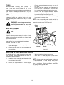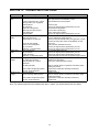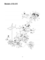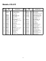
1
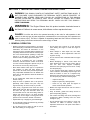
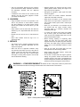
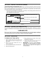
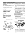
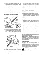
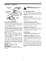
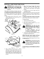
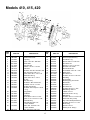
OPERATOR’S MANUAL
REAR TINE
TILLER
Models
410 Thru 420
IMPORTANT: READ SAFETY RULES AND INSTRUCTIONS CAREFULLY
Warning: This unit is equipped with an internal combustion engine and should not be used on or near any unimproved forestcovered, brush-covered or grass-covered land unless the engine’s exhaust system is equipped with a spark arrester meeting
applicable local or state laws (if any). If a spark arrester is used, it should be maintained in effective working order by the operator.
In the State of California the above is required by law (Section 4442 of the California Public Resources Code). Other states may have
similar laws. Federal laws apply on federal lands. A spark arrester for the muffler is available through your nearest engine authorized
service dealer or contact the service department, P.O. Box 368022 Cleveland, Ohio 44136-9722.
MTD PRODUCTS INC. P.O. BOX 368022 CLEVELAND, OHIO 44136-9722
PRINTED IN U.S.A.
FORM NO. 770-8879A
SECTION 1: IMPORTANT SAFE OPERATION PRACTICES
WARNING: THIS SYMBOL POINTS OUT IMPORTANT SAFETY INSTRUCTIONS WHICH, IF
NOT FOLLOWED, COULD ENDANGER THE PERSONAL SAFETY AND/OR PROPERTY OF
YOURSELF AND OTHERS. READ AND FOLLOW ALL INSTRUCTIONS IN THIS MANUAL
BEFORE ATTEMPTING TO OPERATE YOUR TILLER. FAILURE TO COMPLY WITH THESE
INSTRUCTIONS MAY RESULT IN PERSONAL INJURY. WHEN YOU SEE THIS SYMBOL—
HEED ITS WARNING.
WARNING: The Engine Exhaust from this product contains chemicals known to
the State of California to cause cancer, birth defects or other reproductive harm.
DANGER: Your tiller was built to be operated according to the rules for safe operation in this
manual. As with any type of power equipment, carelessness or error on the part of the operator can
result in serious injury. This tiller is capable of amputating hands and feet. Failure to observe the
following safety instructions could result in serious injury or death.
1. GENERAL OPERATION
• Do not place feet or hands on or near the tines
when starting the engine or while the engine is
running.
• Read this operator’s manual carefully in its entirety
before attempting to assemble this machine. Read,
understand, and follow all instructions on the
machine and in the manual(s) before operation. Be
completely familiar with the controls and the proper
use of the machine before operating it. Keep this
manual in a safe place for future and regular
reference and for ordering replacement parts.
• Never attempt to make depth bar, tine width,
cable, handle, or wheel adjustments while the
engine is running.
• Do not leave the tiller unattended with the engine
running.
• Your tiller is a powerful tool, not a plaything.
Therefore, exercise extreme caution at all times.
Your unit has been designed to perform one job: to
till soil. Do not use it for any other purpose.
• Before attempting to remove rocks, bricks and
other objects from tines, stop the engine and be
sure the tines have stopped completely.
Disconnect the spark plug wire and move it away
from the spark plug.
• Never allow children under age 14 to operate the
unit. Children 14 years and older should only
operate the unit under close parental supervision.
Only responsible individuals who are familiar with
these rules of safe operation should be allowed to
use your unit.
• If your machine should start making an unusual
noise or vibration, immediately stop the engine and
allow the machine to come to a complete stop.
Disconnect the spark plug wire and move it away
from the spark plug. Take the following steps:
• Do not operate tiller while under the influence of
alcohol or drugs.
• Inspect for damage.
• Repair or replace any damaged parts.
• Keep the area of operation clear of all persons,
particularly small children and pets. Stop the
engine when they are in the vicinity of your tiller.
• Check for any loose parts and tighten to
assure continued safe operation.
• Wear sturdy, rough-soled work shoes and close
fitting slacks and shirt. Shirt and slacks that cover
the arms and legs and steel-toed shoes are
recommended. Do not wear loose fitting clothes or
jewelry and secure hair so it is above shoulder
length. They can be caught in moving parts. Never
operate a unit in bare feet, sandals or sneakers.
• Muffler and engine become hot and can cause a
burn. Do not touch.
• Keep all shields, guards and safety devices in
place and operating properly.
• Use caution when tilling near fences, buildings and
underground utilities. Rotating tines can cause
damage or injury.
• Operate tiller only in daylight or good artificial light.
• Do not operate engine if air cleaner or cover over
carburetor air intake is removed, except for
adjustment. Removal of such parts could create a
fire hazard.
• Do not start tiller unless the shift lever (if provided)
is in the neutral (N) position.
• Do not allow anyone to stand or walk in front of
tiller when starting or running engine.
2
• Replace gasoline cap securely and wipe off any
spilled gasoline before starting the engine as it
may cause a fire or explosion.
• Only use accessories approved for this machine
by the manufacturer. Read, understand, and follow
all instructions provided with the approved
accessory.
• Extinguish all cigarettes, cigars, pipes and other
sources of ignition.
• If situations occur which are not covered by this
manual, use care and good judgment. Contact
your dealer for assistance.
• Never refuel unit indoors because flammable
vapors will accumulate in the area.
2. CHILDREN
• Never store the machine or fuel container inside
where there is an open flame or spark such as a
gas hot water heater, space heater, clothes dryer
or furnace.
• Tragic accidents can occur if the operator is not
alert to the presence of small children. Children
are often attracted to the tilling activity. Never
assume that children will remain where you last
saw them.
• Never run your machine in an enclosed area as
the exhaust from the engine contains carbon
monoxide, which is a odorless, tasteless and
deadly poisonous gas.
• Keep children out of the work area and under the
watchful eye of a responsible adult other than the
operator.
• To reduce fire hazard, keep engine and muffler
free of leaves, grass, and other debris build-up.
Clean up fuel and oil spillage. Allow unit to cool at
least 5 minutes before storing.
• Be alert and turn the unit off if a child enters the
area.
• Never allow children under the age of 14 to
operate the tiller.
• Before cleaning, repairing, or inspecting, make
certain the tines and all moving parts have
stopped. Disconnect the spark plug wire and keep
wire away from spark plug to prevent accidental
starting. Do not use flammable solutions to clean
air filter.
3. SERVICE
• Use extreme care in handling gasoline and other
fuels. They are extremely flammable and the
vapors are explosive.
• Keep all nuts, bolts, and screws tight to be sure
the equipment is in safe working condition.
• Store fuel and oil in approved containers, away
from heat and open flame, and out of the reach of
children. Check and add fuel before starting the
engine. Never remove gas cap or add fuel while
the engine is running. Allow engine to cool at least
two minutes before refueling.
• Never tamper with safety devices. Check their
proper operation regularly.
• Do not alter or tamper with the engine’s governor
setting. The governor controls the maximum safe
operating speed of the engine. Overspeeding the
engine is dangerous and will cause damage to the
engine and to other moving parts of the machine.
WARNING — YOUR RESPONSIBILITY: Restrict the use of this power machine to persons who
read, understand and follow the warnings and instructions in this manual and on the machine.
Figure 1 Safety labels found on your unit
3
SECTION 2: FINDING YOUR MODEL NUMBER
This Operator’s Manual is an important part of your new tiller. It will help you assemble, prepare and maintain
your tiller. Please read and understand what it says.
Before you start to prepare your tiller for its first use, please locate the model plate and copy the information
from it in this Operators Manual. The information on the model plate is very important if you need help from
your dealer or the MTD customer support department.
• Every tiller has a model plate. You can locate it by standing in the operating position behind the unit
and looking down at the center of the rear tine cover.
• The model plate will look like Figure 2.
This is where your model number will be.
XXX-X-XXX-X-XXX XXXXXXXXXXX
This is where your serial number will be.
Copy the model number here:
MTD PRODUCTS INC
Copy the serial number here:
CLEVELAND , OHIO 44136
Figure 2
SECTION 3: CALLING CUSTOMER SUPPORT
If you are having difficulty assembling this product or if you have any question regarding the controls,
operation or maintenance of this unit, please call the Customer Support Department. You can reach them by
calling:
1-800-800-7310
Before you call, make sure that you have both your model and serial number ready. By having the model and
serial number ready, you help the Customer Support Representative give you faster service. To find your
units model and serial number, see SECTION 2: FINDING YOUR MODEL NUMBER.
SECTION 4: UNPACKING
TO REMOVE UNIT FROM CARTON
5. Roll or slide unit out of carton. Check carton
thoroughly for loose parts.
1. Remove staples, break glue on top flaps, or cut
tape at carton end and peel along top flap to
open carton.
6. Extend control cable and lay on the floor. Be
careful not to bend or kink control cable.
2. Remove loose parts included with unit (i.e.,
owner’s manual, etc.).
IMPORTANT: This unit is shipped WITHOUT
GASOLINE or OIL. After assembly, see separate
engine manual for proper fuel and engine oil
recommendations.
3. Cut along dotted lines and lay carton down flat.
4. Remove packing material.
4
SECTION 5: ASSEMBLY INSTRUCTIONS
This instruction manual covers several different
model tillers. Follow only those instructions which
pertain to your unit.
1. Tip the tiller forward so it rests on front
counterweight.
2. Unthread the “T” knob from the top of the depth
stake, and remove the flat washer and hex bolt.
Remove the hairpin clip from the clevis pin. See
Figure 3.
NOTE: Left and right is determined from the
operator’s position, standing behind the tiller.
3. Raise the tine shield hinge flap assembly. Insert
the depth stake assembly in the slot (under the
tine shield) and up through the tine shield
assembly as shown in Figure 3.
TOOLS REQUIRED FOR ASSEMBLY
(2) 1/2" Wrenches*
(1) 9/16" Wrench*
(1) Pair of Pliers
*Two adjustable wrenches may be used.
4. Insert clevis pin through the tine shield and
depth stake assemblies. Secure with hairpin clip.
5. Insert hex bolt into the top hole of the depth
stake assembly. Place flat washer on the hex
bolt and thread “T” knob onto the hex bolt. See
Figure 3. Tighten securely.
LOOSE PARTS IN CARTON
(1)
(1)
(1)
(1)
Depth Stake
Handle Assembly
Shift Rod
Handle Adjustment Rod (Model 420 Only)
6. Tip the tiller back down so it rests on the tines.
Attaching the Handle Assembly
NOTE: All hardware needed for assembly is
1. Remove the Handle Adjustment Lock, Flange
Nut Retainer Bracket, Shoulder Bolt and Lock
Nut from the Pivot Bracket.
attached to the loose parts or the tiller.
ATTACHING THE DEPTH STAKE
ASSEMBLY
2. Place the handle assembly in position in the
handle pivot bracket lining the upper holes in
the handle with the slots in the pivot bracket.
See Figure 4.
T-Knob, Flat Washer, Hex Bolt
Flange Nut Retainer Bracket
Shoulder Bolt
Lock Nut
Handle Adjustment
Lock
Flange Nut
Tine Shield
Hinge Flap
Clevis Pin
Hairpin Clip
Pivot Bracket
Figure 4
3. Lift up the handle assembly and align the
bottom holes in the handle assembly with the
holes in the pivot bracket. Insert hex bolt (with
Hex nut retainer attached through the round
hole). The head of hex bolt and retainer bracket
should be to the right hand side of the unit. See
Figure 5.
Depth Stake
Figure 3
5
Flange Nut Retainer Bracket
Shoulder Bolt
Lock Nut
T-Handles
Lift up
Handle
Gear Shift
Rod
Handle
Adjustment Rod
(Model 420 Only)
Figure 5
Figure 7
4. Place the hex opening of the hex nut retainer
bracket over the flange nut securing the handle
adjustment lock and install the lock nut on the
lower shoulder bolt. See Figure 6.
Hex Hole in
Retainer Bracket
over Flange Nut
Shift Cover
Gear Shift Rod
Opening
Handle Adjustment
Lock
Rubber Washer
Flat Washer
Hairpin Clip
Figure 8
3. Install the nut and T-handle on the gear shift rod.
ATTACHING THE HANDLE ADJUSTMENT
ROD
Figure 6
5. Pivot handle assembly into position desired.
Tighten the bottom bolt and nut securely.
Tighten the handle adjustment lock.
(Model 420 Only)
ATTACHING THE GEAR SHIFT ROD
NOTE: Model 420 tiller has two control rods. The
gear shift rod is the longer rod.
1. Remove the T-handle, nut, hairpin clip, flat
washer and rubber washer from the end of the
gear shift rod. Slide the rod up through the
bracket on the front of the handle assembly
(use the right hand hole for Model 420). See
Figure 7.
Handle
Adjustment
Rod
Positioner
Bracket
2. Insert the end of the gear shift rod through the
opening in the top of the shift cover, and into
the shift bracket. See Figure 8. Secure with
rubber washer first, then flat washer and hairpin
clip.
Rubber
Washer
Figure 9
6
Hairpin
Clip
3. Pull the cable upwards to obtain slack, and,
from right to left, hook the “Z” end of the cable
into the bracket on the clutch control (beneath
the handle panel) as shown in Figure 11.
Tighten the nut against the cable bracket.
NOTE: Do not overtighten control wire. Too much
tension may cause it to break.
1. Remove the T-handle, nut, hairpin clip, and
rubber washer from the ends of the handle
adjustment rod. Slide the rod up through the left
side of the bracket on the front of the handle
assembly. Refer to Figure 7.
2. Slide the rubber washer on the unthreaded end
of the handle adjustment rod. Insert the end of
the handle adjustment rod into the positioner
bracket beneath the handle, on top of the tine
shield. See Figure 9. Secure with hairpin clip.
FINAL CLUTCH ADJUSTMENT
IMPORTANT: Service the engine with oil and
gasoline before checking this adjustment. Refer to
the separate engine manual packed with your tiller.
1. Position the tiller so the front counterweight is
against a solid object, such as a wall. With the
gear selection lever in NEUTRAL, start the
engine. Refer to Operation section.
NOTE: Keep hands out of belt area while unit is
operating.
3. Reinstall the nut and T-handle.
ATTACHING THE CLUTCH CABLE
Handle
Adjustment
Lock
Cable
Clip
2. Standing on the right side of the tiller, visually
examine the belt (inside the belt cover). It
should not be turning.
If the belt turns with the unit in neutral,
adjust by moving the hex nut below the cable
bracket down a few turns. See Figure 11.
Tighten the upper hex nut against the bracket.
3. Now move the shift lever to FORWARD
(Wheels Forward) position. Carefully engage
the clutch by squeezing the clutch handle
against the handle. The wheels should spin.
4. If the wheels do not spin with the unit in
forward, adjust by moving the hex nut which is
above the cable bracket up a few turns. Tighten
the bottom hex nut against the bracket.
Recheck both adjustments, and readjust as necessary. Make certain hex nuts at cable bracket are tight
(do not overtighten control cable).
NOTE: If additional adjustment is required, it may
be necessary to remove the belt cover, and move
the hex nuts at the other end of the clutch cable to
increase belt tension.
Flange Lock Nut
Figure 10
1. Route the clutch cable underneath the handle
and through the cable clip. Be careful not to
bend or kink the cable. Refer to Figure 10.
Remove one hex nut from the threaded casing
on the end of the cable. See Figure 11.
Hex
Nuts
Lock
Washer
TIRE PRESSURE
Slot in
Cable
Bracket
The tires on your unit may be over-inflated for
shipping purposes. Reduce the tire pressure before
operating the unit. Recommended operating tire
pressure is approximately 14 p.s.i. on 14 inch tires
and 20 p.s.i. on 16 inch tires. (Check sidewall of tire
for tire manufacturer’s recommended pressure).
“Z” End
of Cable
Figure 11 Viewed beneath handle panel.
WARNING: Maximum tire pressure
2. Slip the wire up through the slot on the cable
bracket underneath the handle. Push the end of
the casing up through the cable bracket.
Rethread the hex nut on the end of the cable.
Do not tighten at this time.
under any circumstances is 30 p.s.i.
Equal
tire
pressure
should
be
maintained on both tires.
7
SECTION 6: CONTROLS
WARNING: Make certain unit is in
Gear Selection
Handle
Handle Height
Adjustment
Lock
NEUTRAL when starting the engine.
CLUTCH HANDLE - (Bail)
The clutch handle (bail) is located beneath the
handle. See Figure 12. Squeezing the clutch handle
against the handle engages the wheel and tine drive
mechanisms.
Handle
Clutch
Adjustment
Handle
(Side to Side)
(Bail)
(Model 420 Only)
THROTTLE CONTROL
Depth
Stake
The throttle control lever is located on the engine. It
controls the engine speed and stops the engine.
See Figure 13.
Figure 12
GEAR SELECTION HANDLE
CHOKE LEVER (Model 410/420)
The gear selection handle is located on the front of
the handle assembly (right hand handle on Model
420). It is used to select NEUTRAL, REVERSE, or
one of the FORWARD modes.
This tiller is designed for the gear selection handle
to be moved while the engine is running. (It will be
difficult to obtain all four positions with the engine
off.) Pull or push the handle so that the indicator on
top of shift cover points to the area of the operating
mode desired. See Figure 12.
NOTE: If difficulty is encountered in moving the
gear selection handle, refer to following helpful hints.
To shift into forward or reverse wheel drive, move
tiller forward slightly, then backward, to allow the
gears to synchronize.
To shift into forward wheels and tine drive, push
forward slightly on the gear selection handle and
slowly engage the clutch handle allowing the gears
to synchronize. To stop forward movement, and tine
drive, release the clutch handle. Do not shift gears
with the clutch handle engaged except when
engaging the tines.
REVERSE—Reverse wheel drive only.
NEUTRAL—Transmission is in neutral.
FORWARD Modes:
Wheels Forward— Forward wheel drive only.
Tines Reverse— Forward wheel drive and reverse
tine drive.
The choke lever is located above the throttle. It is
used to enrich the fuel mixture in the carburetor
when starting a cold engine. See Figure 13.
PRIMER BUTTON (Model 415)
The primer button is located behind the air cleaner.
It is used to enrich the fuel mixture in the carburetor
when starting a cold engine. See Figure 13.
DEPTH STAKE
The depth stake controls the tilling depth. Refer to
‘‘How to Use Your Tiller’’ section on page 10.
HANDLE ADJUSTMENT (See Figure 12)
The handle may be adjusted to the height desired.
Loosen the handle height adjustment lock a few
turns. Pivot handle up or down to desired position.
Tighten lock.
On Model 420, the handle may also be adjusted to
be in line with the tiller, or swung to the left or right
so the operator is not walking in the freshly tilled
soil. To adjust the handle position from side to side,
pull the handle adjustment handle back, pivot the
tiller handle to desired position and release the
handle.
8
SECTION 7: OPERATION
NOTE: Engine is shipped without oil.
5. Pull starter handle rapidly. Do not allow handle
to snap back. Allow it to rewind slowly while
keeping a firm hold on the starter handle.
BEFORE STARTING
1. Service engine with oil as instructed in the
separate engine manual packed with your unit.
6. Repeat steps 4 and 5 until engine starts.
7. As engine warms up and begins to operate
evenly, move choke lever gradually to RUN
position. If engine falters, return to choke
position, then slowly move to RUN position.
Refer to engine manual for additional engine
information.
2. Fill fuel tank with clean, fresh, lead-free, lowlead or regular grade leaded gasoline.
TO START ENGINE
NOTE: When pushing the unit with the engine off,
you will hear a ratcheting sound (gear noise) which
is normal.
Model 415
WARNING: Be
sure no one is
standing in front of the tiller while the
engine is running or being started.
1. Place gear selection lever in NEUTRAL.
2. Place the engine speed control in the START
position.
Model 410/420
3. Push primer two (2) or three (3) times (see
Figure 13). Wait about two (2) seconds between
each push.
1. Place gear selection lever in NEUTRAL.
2. Place the throttle control lever in FAST position.
See Figure 13.
NOTE: Primer may be needed to restart a warm
engine after a short shutdown.
3. Move choke lever to CHOKE position.
NOTE: A warm engine may not require choking.
4. Stand at side of tiller. Grasp the starter handle
and pull out slowly, until it pulls slightly harder.
Let rope rewind slowly.
Choke
5. Pull rope with a rapid full arm stroke. Do not
allow handle to snap back. Allow it to rewind
slowly while keeping a firm hold on the starter
handle.
NOTE: If engine fails to start after three (3) pulls,
push primer two (2) times and pull starter rope again.
6. Repeat steps 4 and 5 until engine starts. Refer
to engine manual for additional engine
information.
NOTE: After starting and prior to using the tiller for
the first time, be certain to check the clutch
adjustment as described in “Checking the Clutch
Adjustment” section of the Assembly Instructions.
Throttle Control
Model 410/420
Air
Cleaner
Primer
Fast
Stop
TO STOP ENGINE
1. Move throttle control to STOP or OFF position.
2. Disconnect spark plug wire and ground to
prevent accidentally starting while equipment is
unattended.
NOTE: After the first ten hours of operation, recheck
the clutch adjustment. Refer to final clutch
adjustment in Assembly Instructions.
Throttle
Model 415
Figure 13
4. Stand at side of tiller. Grasp the starter handle
and pull out slowly, until it pulls slightly harder.
Let rope rewind slowly.
9
SECTION 8: HOW TO USE YOUR TILLER
WARNING: When operating the tiller
for the first time, use the depth stake
setting that gives 1 inch of tilling depth
(second hole from the top). Refer to
Figure 14.
3. When tilling loose soil, depth stake may be
raised to its highest position (use bottom
adjustment hole) to give the deepest tilling
depth. Raise the side shields to their highest
position.
Tilling depth is controlled by the depth stake which
can be adjusted to five different settings. See Figure
14. Adjust the side shields as shown in Figure 15,
as you adjust the depth stake. Be certain spark plug
wire is disconnected and grounded against the
engine.
1. When using the tiller for the first time, use the
second adjustment hole from the top (1" of
tilling depth). See Figure 14.
4. To transport tiller, lower the depth stake (use
top adjustment hole).
To adjust the depth stake, remove the clevis pin and
hairpin clip. See Figure 14. Move the depth stake to
the desired setting. Secure with the clevis pin and
hairpin clip.
To adjust the side shields, remove the wing nuts.
See Figure 15. Move the side shield to the desired
position. Replace the wing nuts. Tighten securely.
To operate the tiller:
1. Select the depth stake setting.
Use This
Position
First Time
2. Start engine as instructed on page 9.
Transport
Position
3. Move gear selection handle to one of the
forward modes or reverse.
1"
Clevis
Pin
3"
Hairpin
Clip
WARNING: Do not move the gear
selection handle with the wheels or
tines engaged. Make certain the unit is
stopped completely before changing
the gear selection.
A
partial
engagement
may
be
necessary when engaging tines. Refer
to “Controls” section on page 8.
5"
7"
4. Squeeze the clutch handle against the handle
to engage the wheels and tines.
Figure 14
Use This
Hole for
Lowest (Shallowest)
Position
NOTE: Make certain the gear selection indicator is
correctly positioned before engaging the clutch
handle. If it is between gears, the engine will stall.
To transport tiller, do not engage the tines. Select
the wheel drive only.
Side
Shields
WARNING: Do not push down on the
handles so that the wheels are lifted off
the ground while using the tine drive,
or the tiller could move backward and
cause personal injury.
Use This Hole for
Highest (Deepest)
Position
Figure 15
For best results, it is recommended the garden be
tilled twice (lengthwise, then widthwise) to pulverize
the soil.
2. When breaking up sod and for shallow
cultivation, use the setting which gives 1" of
tilling depth (second hole from the top). Place
the side shields in their lowest position. For
further depth, raise the depth stake and side
shields and make one or two more passes over
the area.
10
SECTION 9: ADJUSTMENTS
HANDLE ADJUSTMENT
CARBURETOR ADJUSTMENT
The handle height may be adjusted. On Model 420,
the handle may also be adjusted to be in line with
the tiller, or swung to the left or right. Refer to the
Control section for details of handle adjustment.
WARNING: If any adjustments are
made to the engine while the engine is
running, (e.g. carburetor), disengage all
clutches and tines. Keep clear of all
moving parts. Be careful of heated
surfaces and muffler.
BELT TENSION ADJUSTMENT
Periodic adjustment of the belt tension may be
required due to normal stretch and wear on the belt.
Adjustment is needed if the tines or wheels seem to
hesitate while turning, but the engine maintains the
same speed.
Never make unnecessary adjustments. The factory
settings are correct for most applications. If
adjustments are needed, refer to the separate
engine manual packed with your tiller.
To adjust the tension on the belt, refer to final clutch
adjustment in Assembly Instructions.
SECTION 10: LUBRICATION
Transmission—The transmission is pre-lubricated
and sealed at the factory. It requires no checking
unless the transmission is disassembled. To fill with
grease, lay the right half of the transmission on its
side. Add 22 ounces of Benalene 920 grease.
Assemble the left half to it. This grease can be
obtained at your nearest authorized dealer. Order
part number 737-0300.
Clutch Handle—Lubricate the pivot point on the
clutch handle and the cable at least once a season
with light oil. The control must operate freely in both
directions.
Pivot Points—Lubricate all pivot points and
linkages at least once a season with light oil.
Tine Shafts—Remove tine assemblies and
lubricate the tine shafts at least once a season.
Wheel Shafts—Remove wheel assemblies and
lubricate the axle shafts at least once a season.
SECTION 11: MAINTENANCE
WARNING: Disconnect
The spark plug should be cleaned and the gap
reset every 25 hours of engine operation. Spark
plug replacement is recommended at the start of
each tiller season; check engine manual for correct
plug type and gap specification.
Clean the engine regularly with a cloth or brush.
Keep the cooling system (blower housing area)
clean to permit proper air circulation which is
essential to engine performance and life. Be certain
to remove all dirt and combustible debris from
muffler area.
the
spark
plug wire and ground it against the
engine before performing any repairs
or maintenance.
ENGINE
Refer to the separate engine manual for engine
maintenance instructions.
Maintain engine oil as instructed in the separate
engine manual packed with your unit. Read and
follow instructions carefully.
Service air cleaner every ten hours under normal
conditions. Clean every hour under extremely dusty
conditions. Poor engine performance and flooding
usually indicates that the air cleaner should be
serviced. To service the air cleaner, refer to the
separate engine manual packed with your unit.
CLEANING THE TINE AREA
Clean the underside of the tine shield after each
use. The dirt washes off the tines easier if washed
off immediately instead of after it dries.
IMPORTANT: Never run your engine without air
cleaner completely assembled.
11
TIRES
Remove two torx head screws from the top of
belt cover.
Remove two hex cap nuts and flat washers
from front side of the belt cover. Remove the
hex nut and flat washer at the back of the cover.
Recommended
operating
tire
pressure
is
approximately 14 p.s.i. on 14 inch tires and 20 p.s.i.
on 16 inch tires. (Check sidewall of tire for tire
manufacturer’s recommended pressure). Maximum
tire pressure under any circumstances is 30 p.s.i.
Equal tire pressure should be maintained on both
tires.
When installing a tire to the rim, be certain rim is
clean and free of rust. Lubricate both the tire and
rim generously. Never inflate to over 30 p.s.i. to seat
beads.
NOTE: Upon reassembly, make certain the belt is
WARNING: Excessive pressure (over
routed over the idler pulley and inside of belt
keepers by engine pulley. See Figure 16.
3. Remove the belt keeper assembly located
behind the engine pulley by removing two hex
bolts and lock washers. See Figure 16.
4. Remove belt. Reassemble new belt, following
instructions in reverse order.
30 p.s.i.) when seating beads may
cause tire/rim assembly to burst with
force sufficient to cause serious injury.
Engine
Pulley
Belt Keeper
BELT REPLACEMENT
CAUTION: Do not use an off-the-shelf
belt.
Your tiller has been engineered with a belt made of
special material (Kevlar Tensile) for longer life and
better performance. It should not be replaced with
an off-the-shelf belt.
If belt replacement is required, order belt or belts by
part number from your nearest authorized dealer.
Part No. 754-0438—‘‘V’’ Belt
1. Disconnect and ground the spark plug wire
against the engine.
Hex Bolts
Belt
Keeper
2. Remove the belt cover from the left side of the
tiller as follows.
Idler
Pulley
Figure 16
SECTION 12: OFF-SEASON STORAGE
If the tiller will not be used for a period longer than
30 days, the following steps should be taken to
prepare the tiller for storage.
1. Clean the exterior of engine and the entire tiller
thoroughly. Lubricate the tiller as described in
the lubrication instructions.
3. Wipe tines with oiled rag to prevent rust.
4. Store tiller in a clean, dry area. Do not store
next to corrosive materials, such as fertilizer.
NOTE: When storing any type of power equipment
in an unventilated or metal storage shed, care
should be taken to rustproof the equipment. Using a
light oil or silicone, coat the equipment, especially
any springs, bearings and cables.
2. Refer to the engine manual for correct engine
storage instructions.
12
SECTION 13: TROUBLE SHOOTING GUIDE
Trouble
Possible Cause(s)
Corrective Action
Engine fails to
start
Fuel tank empty, or stale fuel.
Fill tank with clean, fresh gasoline. Fuel will not last over
thirty days unless a fuel stabilizer is used.
Move throttle lever to start position.
Engine runs
erratic
Engine overheats
Tines do not
engage
Wheels do not
engage
Throttle control lever not in correct
starting position (if so equipped).
Blocked fuel line.
Dirty aircleaner.
Choke not in ON position.
Spark plug wire disconnected.
Faulty spark plug.
Engine flooded.
Unit running on CHOKE.
Spark plug wire loose.
Blocked fuel line or stale fuel.
Vent in gas cap plugged.
Water or dirt in fuel system.
Dirty air cleaner.
Carburetor out of adjustment.
Engine oil level low.
Dirty air cleaner.
Air flow restricted.
Carburetor not adjusted properly.
Foreign object lodged in tines.
Tine clevis pin(s) missing.
Pulley and idler not in correct
adjustment.
Not shifting properly.
Control cable not adjusted properly.
Belt worn and/or stretched.
Clevis pin missing.
Tiller is not being shifted properly.
Control cable not adjusted properly.
Belt worn and/or stretched.
Clean fuel line.
Refer to the engine manual packed with your unit.
Move switch to ON position.
Connect wire to spark plug.
Clean, adjust gap or replace.
Refer to the engine manual packed with your unit.
Move choke lever to OFF position.
Connect and tighten spark plug wire.
Clean fuel line; fill tank with clean, fresh gasoline. Fuel will
not last over thirty days unless a fuel stabilizer is used.
Clear vent.
Drain fuel tank. Refill with fresh fuel.
Refer to the engine manual packed with your unit.
Refer to the engine manual packed with your unit.
Fill crankcase with proper oil.
Refer to the engine manual packed with your unit.
Refer to the engine manual packed with your unit.
Adjust carburetor as instructed in separate engine manual.
Dislodge foreign object.
Replace tine clevis pin(s).
Take unit to authorized service dealer.
Refer to controls section of operator’s manual for proper
shifting procedures.
Adjust control cable (see assembly instructions).
Replace belt.
Replace clevis pin.
Refer to controls section of operator’s manual for proper
shifting procedures.
Adjust control cable (see assembly instructions).
Replace belt.
Note: For repairs beyond the minor adjustments above, contact your local authorized service dealer.
13
Models 410-415
14
Models 410-415
REF.
NO.
PART
NO
1
2
3
735-0246
647-0014
710-1017
4
5
6
7
8
9
11
12
13
14
15
16
17
21
22
23
24
28
29
30
31
32
786-0131
786-0098
786-0118
720-0278
720-0210A
712-3008
735-0127
736-0204
747-0902
714-0104
649-0017
710-0896
726-0330
746-0916
786-0120
736-0117
710-0253
715-0120
686-0095
711-0415
714-0149B
642-0015
642-0016
REF.
NO.
DESCRIPTION
Vinyl End Plug
Clutch Control Ass’y.
Torx Mach. AB-Tap Scr.
1/4 x .62" Lg.
Handle Cover
Retaining Brkt.—R.H.
Retaining Brkt.—L.H.
Grip (2 Req’d.)
Knob
Hex Jam Nut 3/8-16 Thd.
Rubber Washer
Fl-Wash. .344" I.D. x .6" O.D.
Gear Shift Rod
Hairpin Clip
Handle Ass’y.
Tap Scr. 1/4-14 x 5/8" Lg.
Cable Clip
Clutch Cable
Depth Bar
Fl-Wash. 3/8" I.D. x 5/8" O.D.
Hex Bolt 3/8-16 x 1" Lg.*
Spiral Pin 3/16" x 1"
Shift Crank Ass’y.
Clevis Pin
Hairpin Clip
Tine Ass’y.—L.H.
Tine Ass’y.—R.H. (Not Shown)
33
34
35
36
38
39
40
43
786-0090
786-0113
686-0044A
738-0849
710-3002
710-3097
712-0798
712-3004A
44
45
46
47
48
49
50
51
786-0076
786-0077
711-0415
786-0085
747-0432
726-0106
710-0189
786-0101A
786-0168
710-1017
786-0109
786-0108
784-0191
712-0379
750-0885
784-0190
712-0421
736-0169
52
54
55
56
57
58
59
60
61
15
PART
NO
DESCRIPTION
N
N
Side Shield
Rear Tine Shield
End Cover Ass’y.
Hex Cap Bolt 5/16-18 x 1.25"
Hex Bolt 5/16-18 x .75" Lg.
Carriage Bolt 3/8-16 x 1" Lg.
Hex Ins. L-Nut 3/8-16 Thd.
Hex Flange Top L-Nut
5/16-18 Thd.
Tine Shield Brkt.—R.H.
Tine Shield Brkt.—L.H.
Clevis Pin .375" Dia.
Tine Shield
Tiller Flap Rod
Cap Speed Nut
Hex Bolt 5/16-18 x 3" Lg.
Shift Cover (410/420)
Shift Cover (415)
Torx Mach. AB-Tap Scr. 1/4 x
Handle Brkt.—L.H.
Handle Brkt.—R.H.
Hex Nut Retainer Brkt.
Hex Flange Nut 3/8-24 Thd.
Spacer .322 Dia.
Handle Adjustment Crank
Knob 5/16-18 Thd.
L-Washer 3/8" I.D.
Models 410, 415, 420
REF.
NO.
1
2
3
4
5
6
7
8
9
10
11
12
13
14
15
16
17
18
19
20
21
22
23
PART NO.
710-0118
712-3004A
786-0107
710-1017
738-0899
786-0117
786-0100
736-0142
712-0392
756-0634
736-0105
712-0379
754-0438
686-0031
736-0119
710-0237
738-0876
712-0266
756-0405
710-0152
736-0217
736-0258
756-0972
REF.
NO.
DESCRIPTION
24
25
26
27
28
29
30
31
Hex Bolt 5/16-18 x .75" Lg.
Hex Top L-Nut 5/16-18 Thd.
Cable Mtg. Bracket
Torx Mach. AB-Tap Scr. 1/4 x .6" Lg
Belt Cover Bolt
Shift Cover Bracket
Belt Cover
Fl-Wash. .281" I.D. x .5" O.D.
Hex Cap Nut 1/4-28 Thd.
Flat Pulley 8" O.D.
Bell-Wash. .38" I.D. x .88" O.D.
Hex Flange Nut.
“V”-Belt
Belt Keeper Brkt.
L-Wash. 5/16" I.D.
Hex Bolt 5/16-24 x .62" Lg.
Shld. Nut
Hex Jam L-Nut 3/8-16 Thd.
Fl-Idler w/Flanges
Hex Bolt 3/8-24 x 1" Lg.
L-Wash. 3/8" I.D.
Fl-Wash. 3/8" I.D. x 1" O.D.
Outer Engine Pulley Half
32
34
35
36
37
38
41
42
43
16
PART NO.
756-0971
786-0080
710-0723
746-0916
734-0255
714-0104
711-1017
634-0112
634-0108
634-0110
634-0111
634-0106
634-0107
734-1796
734-0808
619-0009
710-1007
710-3002
712-3004A
—
686-0043A
710-3038
736-0256
DESCRIPTION
Inner Engine Pulley Half
Idler Bracket
Hex Bolt 3/8-16 x 1.25" Lg.
Clutch Cable
Air Valve
Hairpin Clip
Clevis Pin
Rim Only (410)
Rim Only (420)
Wheel Ass’y. Comp.—R.H. (410)
Wheel Ass’y. Comp.—L.H. (410)
Wheel Ass’y. Comp.—R.H. (420)
Wheel Ass’y. Comp.—L.H. (420)
Tire Only (410)
Tire Only (420)
Frame Counterweight
Hex TT-Tap Scr. 3/8-16 Thd.
Hex Bolt 5/16-18 x 1" Lg. (Gr. 5)
Hex Flange L-Nut 5/16-18 Thd.
Engine
Tine Shield Brkt. Ass’y.
Hex Bolt 5/16-18 x 7/8" Lg.
Wash. Fl..635 I.D. x .930 O.D. x .03
Models 410, 415, 420
REF.
NO.
PART NO.
1
2
3
4
5
6
8
9
10
11
12
13
14
721-0295
786-0086
716-0865
750-0938
611-0058
717-1458
736-0351
721-0379
736-0518
686-0039
750-0935
738-0885
750-0936
15
16
17
18
19
617-0004
712-3067
736-0407
712-0378
710-0896
20
21
22
23
24
26
27
732-0863
741-0862
721-0378
736-0163
750-0570
611-0021
713-0226
28
713-0233
29
686-0038
REF.
NO.
DESCRIPTION
Chain Case Gasket
Reinforcement Plate
Snap Ring
Spacer .735" I.D. x .886" O.D.
Wheel Shaft
Spur Gear 46T
Fl-Wash. .76" I.D. x 1.5" O.D.
Shaft Seal
Thr.Wash..445 I.D.x1.92 O.D.x .060
Gear Case Ass’y. Half—L.H.
Spacer .635" I.D. x 1" O.D. x .78
Jack Shaft 2.06" Lg.
Spacer .635" I.D. x 1" O.D. x
.37" Thk.
Gear Idler Ass’y.
Hex Patch L-Nut 7/16-20 Thd.
Bell-Wash. .45" I.D. x 1" O.D.
Hex Nut 7/16-20 Thd.
Hex Wash. Hd. TT-Tap Scr. 1/4-20
x .5" Lg.
Spring Detent
Ball Detent
Shaft Seal
Thrust Wash. 1.03" I.D. x 1.62"
Spacer 1" I.D. x 2" O.D. x .5" Thk.
Tine Shaft Ass’y.
Chain #50 5/8" Pitch x 52
Links—Endless
Chain—#41 1/2" Pitch x 30
Links—Endless
Gear Case Ass’y. Half—R.H.
30
31
32
33
35
36
37
38
39
40
41
42
43
44
45
46
47
49
50
51
52
53
55
56
57
58
59
60
61
—
17
PART NO.
736-0541
617-0002
738-0884
750-0931
717-1411
750-0930
713-0436
717-1405
736-0518
618-0245A
717-1409
736-0442
732-0614
718-0234
716-0235
711-1087
713-0435
717-1451A
736-0336
741-0124
736-0329
710-0258
741-0563
736-0512
686-0094
718-0237
736-0265
726-0331
750-0987
737-0300
DESCRIPTION
N
N
Fl-Wash. 7/16" I.D. x 1-3/8" O.D.
Gear and Sprocket Ass’y.
Jack Shaft 5" Lg.
Spacer .636" I.D. x .86" O.D.
Spur Gear 10T
Spacer 1.5" I.D. x 1.76" O.D.
Sprocket—#41 Chain
Reverse Gear 46T
Thrust Wash. .445" I.D. x 1.92"
Shifter Ass’y.
Spur Gear 17T
Fl-Wash. .69" I.D. x 1.06" O.D.
Wire Ring
Clutch Collar
Retaining Ring .875" Shaft
Drive Shaft
Sprocket 11T
Spur Gear 16T
Fl-Wash. 5/8" I.D. x 1" O.D.
Ball Bearing .669" I.D.
L-Wash. 1/4" I.D.
Hex Bolt 1/4-20 x .62" Lg.
Ball Bearing
Fl-Wash. .281" I.D. x .875" O.D.
Gear Case Ass’y. Comp.
Key—Drive Shaft (Not Shown)
Fl-Wash. .88" I.D. x 1.5" O.D.
Button Plug
Spacer 1.52" I.D.
Grease (40 oz. Req’d.)
Model 420
18
Model 420
REF.
NO.
1
2
3
4
5
6
7
8
9
11
12
13
14
15
16
17
21
22
23
24
28
29
30
31
32
33
34
35
36
PART NO.
735-0246
647-0014
710-1017
786-0131
786-0098
786-0118
720-0278
720-0210A
712-3008
735-0127
736-0204
747-0902
714-0104
649-0016
710-0896
726-0330
746-0916
786-0120
736-0117
710-0253
715-0120
686-0095
711-0415
714-0149B
642-0015
642-0016
786-0090
786-0113
686-0044A
738-0849
DESCRIPTION
N
N
Vinyl End Plug
Clutch Control Ass’y.
Torx Mach. AB-Tap Scr.
Handle Cover
Retaining Brkt.—R.H.
Retaining Brkt.—L.H.
Grip (2 Req’d.)
Knob
Hex Jam Nut 3/8-16 Thd.
Rubber Washer
Fl-Wash. .344" I.D. x .6" O.D.
Gear Shift Rod
Hairpin Clip
Handle Ass’y.
Tap Scr. 1/4-14 x 5/8" Lg.
Cable Clip
Clutch Cable
Depth Bar
Fl-Wash. 3/8" I.D. x 5/8" O.D.
Hex Bolt 3/8-16 x 1" Lg.*
Spiral Pin 3/16" x 1"
Shift Crank Ass’y.
Clevis Pin
Hairpin Clip
Tine Ass’y.—L.H.
Tine Ass’y.—R.H. (Not Shown)
Side Shield
Rear Tine Shield
End Cover Ass’y.
Hex Screw 5/16-18 x .75" Lg.
REF.
NO.
PART NO.
38
39
40
43
44
45
46
47
48
49
50
51
52
710-0118
710-3097
712-0798
712-3004A
786-0076
786-0077
711-0415
786-0085
747-0432
726-0106
710-0521
786-0101A
710-1017
54
55
56
57
59
60
61
62
63
64
65
66
67
68
69
686-0071
686-0048
784-0191
712-0379
784-0190
710-0189
732-0493
712-0375
748-0375
736-0317
712-0386A
714-3021
747-0901
712-0421
736-0169
19
DESCRIPTION
N
Hex Bolt 5/16-18 x .75" Lg.
Carriage Bolt 3/8-16 x 1" Lg.
Hex Nut 3/8-16 Thd.
Hex Fl. Tp. L-Nut 5/16-18 Thd.
Tine Shield Brkt.—R.H.
Tine Shield Brkt.—L.H.
Clevis Pin .375" Dia.
Tine Shield
Tiller Flap Rod
Cap Speed Nut
Hex Bolt 3/8-16 x 3" Lg.
Shift Cover
Torx Mach. AB-Tap Scr.
1/4 x .6"
Handle Positioner Brkt. Ass’y.
Handle Pivot Brkt. Ass’y.
Hex Nut Retainer Brkt.
Hex Flange Nut 3/8-24 Thd.
Handle Adjustment Crank
Hex Bolt 5/16-18 x 3" Lg.
Torsion Spring
Hex L-Nut 3/8-16 Thd.
Handle Swing Link
Bell-Wash. 5/8" I.D.
Hex Slotted Nut 5/8-18 Thd.
Cotter Pin 1/8" x 1-5/8"
Handle Adjustment Rod
Knob 5/16-18 Thd.
L-Washer 3/8" I.D.
MANUFACTURER’S LIMITED WARRANTY FOR:
For TWO YEARS from the date of retail purchase
within the United States of America, its possessions
and territories, MTD PRODUCTS INC will, at its
option, repair or replace, for the original purchaser,
free of charge, any part or parts found to be
defective in material or workmanship. This warranty
covers units which have been operated and
maintained in accordance with the operating
instructions furnished with the unit, and which have
not been subject to misuse, abuse, commercial use,
neglect, accident, improper maintenance or
alteration.
products sold or exported outside of the United
States of America, its possessions and territories,
except those sold through MTD PRODUCTS INC’s
authorized channels of export distribution.
Other Warranties:
1. The engine or component parts thereof carry
separate warranties from their manufacturers.
Please refer to the applicable manufacturer’s
warranty on these items.
2. *Batteries are covered by a 90-day replacement
warranty.
Normal wear parts or components thereof are
subject to separate terms as noted below in the “No
Fault Ninety Day Consumer Warranty” clause.
3. Log splitter pumps, valves and cylinders or
component parts thereof are covered by a one
year warranty.
All normal wear part failures will be covered on this
product for a period of 90 days regardless of cause.
After 90 days, but within the two year period, normal
wear parts failures will be covered ONLY IF caused
by defects in material or workmanship of OTHER
component parts. Normal wear parts are defined as
batteries*, belts, blades, blade adapters, grass
bags, rider deck wheels, seats, snow thrower skid
shoes, shave plates and tires.
4. All other warranties, express or implied,
including
any
implied
warranty
of
merchantability or fitness for a particular
purpose, are hereby expressly disclaimed in
their entirety.
How to obtain service: Warranty service is
available, with proof of purchase, through your local
authorized service dealer. To locate the dealer in
your area, please check the yellow pages or contact
the Customer Service Department of MTD
PRODUCTS INC, P. O. Box 368022, Cleveland,
Ohio 44136-9722. Phone 1 (800) 800-7310. The
return of a complete unit will not be accepted by the
factory unless prior written permission has been
extended by the Customer Service Department of
MTD PRODUCTS INC.
Transportation charges: Transportation charges
for the movement of any power equipment unit or
attachment are the responsibility of the purchaser.
Units exported out of the United States: MTD
PRODUCTS INC does not extend any warranty for
5. The provisions as set forth in this warranty
provide the sole and exclusive remedy of MTD
PRODUCTS INC’s obligations arising from the
sales of its products. MTD PRODUCTS INC will
not be liable for incidental or consequential loss
or damage.
How state law relates to this warranty: This
limited warranty gives you specific legal rights, and
you may also have other rights which vary from
state to state. Certain disclaimers are not allowed in
some states and therefore they may not apply to
you under all circumstances.
NOTE: This warranty does not cover routine
maintenance items such as lubricants, filters, blade
sharpening and tune-ups, or adjustments such as
brake adjustments, clutch adjustments or deck
adjustments. Nor does this warranty cover normal
deterioration of the exterior finish due to use or
exposure.