1
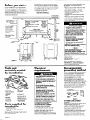
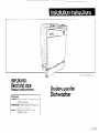
Part No, 3369092 Rev. A
IMPORTANT:
Read and save
these instructions.
’ IMPORTANT:
, Installer: Leave Installation Instructions with
the homeowner.
Homeowner:
Keep Installation Instructions
for future reference,
Save Installation Instructions for local
inspector’s use,
Undercounter
Dishwasher
Proper electrical, drain and water supply
lines must be available or must be installed
as specified within shaded area. Plumbing
and wiring should not cross in front of motor
or dishwasher legs. See Electrical, Water
and Drain requirements.
Before you start...
Proper installation is your responsibility.
Make sure you have everything necessary
for correct installation. It is the personal
responsibility and obligation of the
customer to contact a qualified installer to
assure that electrical and plumbing
installations meet all national and local
codes and ordinances.
IMPORTANT: Observe all governing
codes and ordinances.
l
l
Corner location
2” min. door to
cabinet or wall -
Cut openings Water line: l/2” hole or larger.
Drain line: 1- l/2” hole
or larger.
Power supply cord: 1- l/2” max.
hole.
Direct wiring: 3/4” min. hole.
DO NOT pinch
power supply
cord or kink
power supply
cable between
dishwasher and
cabinet.
l
l
A
Electrical ground.
is required.
See “Electrical
requirements. II
Check location where dishwasher will
be installed. The location should
provide:
Easy access to water, electricity and
drainage lines.
Convenient loading -the best
position is left or right of kitchen sink.
Opening that is square for proper
dishwasher operation and
appearance.
Cabinet front that is perpendicular
to floor.
Protection so that water inlet valve
and drain cannot freeze.
l/4” minimum clearance between
motor and flooring to prevent motor
from overheating.
Grommet
required for
electrical
cable or
power supply
cord hole cut
in a metal
cabinet.
The unshaded area must be free
of pipes or wires.
Electrical outlet must be installed
in an adjacent
cabinet.
I
:)!I
l
l
24”
Electrical Shock Hazard
It is the personal responsibility and
obligation of the customer to
contact a qualified electrician to
assure that the electrical installation
is adequate and is in conformance
with the National Electrical Code,
ANSI/NFPA 70 - latest edition* and
all local codes and ordinances.
Failure to follow these instructions
could result in electrical shock or
other personal injury.
Electrical wiring and components
must not contact any plumbing
material or drain hose.
Cabinet opening must completely
enclose sides, top and back of
dishwasher.
Failure to do so may result in personal
injury from exposed wiring.
Personal Injuryy;o$ct
Damage
l
%I
4 ..L
-1
n34” min.
underside
DO NOT install
dishwasher over
carpeted
flooring.
l
l
V
-
24” depth
-23-7/B”
y
width B
r
t
Avoid opening dishwasher door
before dishwasher is installed.
Dishwasher, before it is installed, may
tip over when door is opened,
resulting in personal injury or product
damaae.
‘Side view
33-7/a”
min.
height
Copies of the standards listed may be
obtained from:
Figure
u
1
2
+
*National Fire Protection
Batterymarch
Park
Quincy, Massachusetts
20.3/4”
Tools and
materials needed
for installation:
*
Electrical
requirements
Electrical Shock Hazard
Electrical ground is required on this
appliance.
. If cold water pipe is interrupted by
plastic, non-metallic gaskets or other
insulating materials, Do Not use for
grounding.
Do Not ground to a gas pipe.
Do Not modify the power supply
cord plug. If it does not fit the outlet,
have a proper outlet installed by a
qualified electrician.
Do Not have a fuse in the neutral or
grounding circuit. A fuse in the
neutral or grounding circuit could
result in electrical shock.
Do Not use an extension cord with
this appliance.
Check with a qualified electrician if
you are in doubt as to whether the
appliance is properly grounded.
Failure to follow these instructions
could result in serious injury or death.
l
l
l
electric
l
Phillips screwdriver
l
drill
l
2 adjustable
wrenches
l
pliers
l
measuring
l
l
l
l
tape
l
flat-blade
screwdriver
l
pipe wrench
l
keyhole
saw
tubing cutter
(not shown)
pipe-joint
compound
5116” and l/4”
driver or hex socket
gloves
90” elbow with 3/B”
N.P.T. external
threads on one end.
The size of the other
end must fit your
water supply line.
Parts supplied for
installation:
l
2 drain hose clamps
l
2, No.-10 x l/2”
l
drain hose
Phillips-head
screws
Remove parts from bag. Check that all
parts were supplied.
Panel A
02269
Read and follow the “Electrical
requirements”, “Water requirements”
and “Drain requirements” sections
before installing dishwasher.
l
l
Association
l
l
If codes permit and a separate
grounding wire is used, it is
recommended that a qualified
electrician determine that the
grounding path is adequate.
A 120-volt, 60.Hz, AC-only, 15or 20.
ampere, fused electrical supply is
required. Time-delay fuse or circuit
breaker is recommended. It is
recommended that a separate circuit
serving only this appliance be provided
Recommended
grounding method
For your personal safety, this appliance
must be grounded. This appliance is
equipped with a power supply cord
having a 3-prong grounding plug. To
minimize possible shock hazard, the cord
must be plugged into a mating,
3-prong, grounding-type wall receptacle, grounded in accordance with
National Electrical Code, ANSI/NFPA 70
- latest edition* and all local codes and
ordinances. (See Figure 3.) If a mating
wall receptacle is not available, it is the
personal responsibility and obligation of
the customer to have a properly
grounded, 3-prong, wall receptacle
installed by a qualified electrician.
3-prong,
grounding-type
wall receptacle
3-pron
groundi
plug
power
supply
cord
groundrn<
prong
Figure 3
IF POWER CORD CANNOT
BE USED...
When local codes do not permit use of
a power supply cord with an
undercounter dishwasher, the power
supply cord must be removed and
dishwasher wired directly. To direct wire
this product, order kit #4317979.
Electrical connections must be
contained within the terminal box and
meet all local codes and ordinances.
IF THE POWER SUPPLYCORD IS
REMOVED, THE DISHWASHERMUST BE
CONNECTED WITH COPPER WIRE ONLY.
Water
Requirements
Now start...
ove 4 screws.
with dishwasher in kitchen.
The hot water line to the dishwasher
must provide between 15 - 120 psi water
pressure. The hot water heater should be
set to deliver 140°F water temperature
to the dishwasher for best results.
Use 3/8” O.D. copper tubing or l/2”
plastic tubing minimum inlet line.
Dishwasher inlet valve has 3/8” N.P.T.
internal pipe thread
alternate waterline locations
5
Drain
Requfrements
The drain hose MUST
have a high drain loop,
20” minimum ABOVE
FLOOR, to prevent
backflow or water
siphoning out of
dishwasher during
operation.
NOTE: An air gap MUST BE USEDin
the high drain loop if the drain hose
is connected to house plumbing lower
than 20” above the floor.
Drain hose, supplied, meets AHAM DW- 1
test standards. Cut l-1/2” hole in
cabinet wall for drain hose. Additional
drain line (a minimum of l/2” I.D. and no
longer than 20’) can be used if needed.
n
Remove the 4 screws attaching
access panel and toe panel to
dishwasher using a l/4” hex socket, nut
driver or Phillips screwdriver. Remove
access panel and toe panel.
1
n Rough in water line to the dishwasher cabinet opening using one of
the routing methods shown. Cut l/2” or
larger hole in cabinet wall for water line.
2
n
Install a
shutoff valve in the
water line where it
can be easily
used.
6
3
n
Flush water line into a bucket to
get rid of any particles that may clog
inlet valve. Turn shutoff valve to the
“OFF” position.
Electrical Shock Hazard
Disconnect electrical power at the
service panel (fuse box or circuit
breaker box).
Failure to do so could result in serious
injury or death.
I-----r
n The dishwasher is shipped to be
installed in cabinet opening with a 34”
height. Measure height of cabinet
opening from the front edge of the
underside of cabinet opening to floor.
Check chart for that height opening. Put
the wheels in the required position. The
dishwasher should be installed as level
as possible from front to back.
Loosen and then turn front levelers the
number of times indicated in the chart.
Min.
cutout
Height
Wheel
Position
(See
Illustration)
Number
Of Turns
To Adjust
Levelers
33-710”
1
0
34-1116”
2
3
34-114”
3
6
34-7116”
4
9
For additional
height:
I. Add shims under the wheels.
2. Turn front levelers (each turn adds l/16”
height).
in
You may have this type drain
connector...
electrical
2-l/2”
4
l Cut a 1- l/2” maximum
hole for
power supply cord or a 3/4” minimum
hole for direct wiring in the cabinet or
floor for the electrical wiring to pass
through. If this hole is cut in a wood
cabinet, sand the hole until it is smooth.
If the hole is cut in a metal cabinet, the
hole must be covered by a grommet
(Part No. 3027971, available from your
dealer or parts supplier.
Install wall receptacle on rear or side
wall of a cabinet next to dishwasher
opening as indicated by the shaded
areas shown. Plug dishwasher power
supply cord into this receptacle.
For direct wiring install a 3/4” U. L.-listed
conduit connector to connect the
flexible armored or non-metallic
sheathed, copper cable (with
grounding wire> to the fused
disconnect, circuit breaker or junction
box. Run the cable through the hole in
the cabinet opening. The cable should
extend 24” from the back wall.
Panel B
7
w Put spring-type drain hose clamp
over connector. Push drain hose onto
connector. Use pliers to open clamp
and slide clamp over drain hose and
connector. Check that drain hose is
secure.
If screw-type clamp is supplied instead
of spring-type clamp, use a 5/l 6” nut
driver to tighten drain hose securely to
connector.
-
Alternate drain hose connection
methods:
Recommended drain hose
connection methods:
Floor Damage
Tilt dishwasher backwards on wheels
when moving across floor.
Failure to do so may cause damage
to floor covering.
Drain hose to air gap to waste tee.
Air-gap kit
&Part No.
A
Rubber connector
Drain hose to waste tee.
Cut hose
3
Waste tee <
If local plumbing codes permit,
dishwasher drain hose may be
connected directly to waste tee*. The
waste tee connection MUST be made
ahead of the trap and a minimum of 20”
above the floor.
minimum
clearance
to floor
abbve
8 w Latch dishwasher door. Push
trap.
t
dishwasher into place, sliding drain hose
through hole cut in cabinet opening.
Do not pinch power supply cord or kink
power supply cable between
dishwasher and cabinet. Check that
front leveling legs are firmly against the
floor. Align dishwasher door with
cabinet doors, so that spacing is the
same on both sides.
Drain hose to air gap to disposer.
Drain hose to disposer.
‘5b connector.
9
connector
to fit.
w Connect drain hose to an air gap
or waste tee using one of the
recommended or alternate methods.
Cut hose connector
to fit. if needed.
clearance
to floor
I
If connecting drain hose to an air gap or
waste tee, cut end of drain hose as
shown,
Secure drain hose with screw-type or
spring-type hose clamp (clamp type
varies with models.)
Do Not cut drain hose when connecting
to a 7/8” disposer connector. Knock out
plug from disposer inlet. Secure drain
hose with hose clamp provided.
DO NOT cut ribbed section to shorten
drain hose.
drain hose
Numbers
correspond
to steps.
Panel C
-
clearance
to floor
t
U
Pk
Entry must be
above trap.
I
I
Install air gap (Part No. 300096)’
according to kit instructions. If other
brands of air gaps are used, they should
be checked to make sure they allow for
the same water flow.
Connect the air gap to a waste tee* or
disposer using a rubber connector*.
Most disposers have 7/8” connectors or
special connectors are available at
plumbing supply houses. Be sure to
remove the disposer plug before
connecting the drain hose.
If local plumbing codes permit,
dishwasher drain hose may be
connected directly to disposer. Most
disposers have 7/8” connectors or special
connectors are available at plumbing
supply houses. Be sure to remove the
disposer plug before connecting the
drain hose.
*All parts are available through your
dealer or local hardware or plumbing
store.
/equally
To change door
panel color
spaceda,
Product Damage
Do Not solder within 6” of plastic
water inlet valves.
Failure to follow this instruction could
result in product damage.
water
NOTE: The opposite side of the door
color panel is a different color.
inlet valve
14
n Open door approximatelv
3”
and check’for equal spacing between
inner door and tub sides. If necessary,
loosen screws that fasten dishwasher to
countertop and shift tub. Tighten screws.
Personal
Wear gloves and
carefully.
Cut metal edges
injury or damage
10
11
. Check electrical requirements.
Be sure you have correct electrical
supply and recommended grounding
method. See Panels A and B for proper
connection.
top mounting brackets
attached
to underside
of countertop.
.- -4
1
2
operation. Door should ciose easily
without slamming and open with its own
weight. If necessary, close door and
adjust both door springs by moving
spring ends to different holes in base.
16
n Take a few minutes to read the
Use and Care Guide to fully understand
your new dishwasher.
17
n
Check that all parts have
been installed and no steps were
skipped. Check that you have all the
tools you started with.
18
Do Not
drop
screws
into tub.
n
Turn on electric supply. Start
dishwasher and allow it to complete a
cycle. Check that dishwasher is working
properly and that there are no water
leaks.
n Slide panel(s)
down to clear
console. Use both
hands to bow top and
bottom edge of door
panel(s). Remove
panel(s) from door.
Do Not remove
spacer.
3
H With desired
color facing out,
insert one side of
door panel(s) into
one side of door
frame.
c
. Bow door panel(s)
and insert other side of
door panel(s) into door
frame.
l3SSES
Personal Injury/Product Damage
Hazard
l The dishwasher
must be secured to
the countertop to keep it from tilting
when door is open.
l Do Not drop screws in dishwasher
tub. If screws should fall into pump,
pump and motor damage may
occur.
Failure to follow these instructions
may result in personal injury or
product damage.
n Secure dishwasher to
countertop with two, No. - 10 x l/2”
Phillips-head screws from parts bag. You
MUSTsecure dishwasher to keep it from
tilting when door is opened or closed.
Do Not drop screws in dishwasher tub.
Remove paper from bottom of
dishwasher.
control
console
ti n Push in on
door panel(s) near
the top and slide
panel(s) and
spacer up inside
bottom of control
console.
12
n Open dishwasher
door and
remove all shipping materials, Remove
bottom rack. Place a newspaper or
large sheet of paper over bottom of
dishwasher to protect the pump area
when securing dishwasher to
countertop.
Panel D
may cause personal
to other materials.
H Push up at
each end of
retainer at
bottom of door
panel. Then pull
retainer toward you. Set retainer aside.
n
Connect water pipe or tubina
directly to water inlet valve. Do Not run
pipe or tubing across front of motor or
dishwasher legs. Turn on water supply
and check for leaks.
13
Injury Hazard
handle panels
panel
toe pbnel
19
Replace the access panel
and toe panel. The toe panel must be
positioned to contact floor.
n
lower door
frame
6
n
Lift up and hold panel(s) and
spacer l/4” above lower door frame.
20
n
If changing color of door and
access panel or installing custom
panels, follow the “To change door
panel color” and ‘To change access
panel color” instructions, Panel D and E.
Congratulations!
You have just finished insfalling
your new undercounter
dish washer. Keep lnsfallafion
Instructions available for easy
reference.
/ n Insert retainer over lower edge of
door frame while holding door panel(s)
and spacer up.
8
n
Snap retainer
down into place.
Push down
firmly along entire
length of retainer to
make sure retainer is secure.
Slide door panel(s) down.
6
This panel
is narrower
than
access
panel.
9
File or sand
edges of
goi”vdorn=’
Important: Run fingers along
bottom of retainer to check thal
retainer is lower than the lower door
frame.
n
7
bottom
edge
/ wInset-t retainer over
lower edge of door frame while holding
wood door panel up,
Figure 4
(For models so equipped)
Cut door pa
clear acces
when door is in
open position.
Injury Hazard
handle panels
1
n Push UP
Ill
with thumbs‘on
each end of
access panel
top trim to
unsnap trim.
Remove top trim and set it aside.
I
This panel is wider that door panel.
2
All edges routed to 7/32” thickness.
Top view
L7132” thick
n
facing out, bow
access panel
and insert into
access oanel
frame. Slide panel down into groove
along bottom of access panel frame.
Line up
edges of top trim
with sides of
access panel
frame. Tilt back of
trim down and slide into place. Snap
front of trim down to cover top edge of
access panel.
n
To install
customized wood
panels in door and
access panel
Dishwasher door panel and access
panel (if model is so equipped) can be
customized to match wood cabinets. A
standard l/4” (7/32” actual thickness)
wood panel can be used as is for
customizing the door and access
panels,
A door panel thicker than 7/32”,
requires routing the top and bottom to a
7/32” thickness.
An access panel thicker than 7/32”,
requires routing all four edges to a 7/32”.
It is recommended that a cabinetmaker cut the customized panels
because of the precise cuts required.
(See Figures 4 and 5.)
Figure 5
1
1 n
using
wood
wood
2
Cut wood door and access panels
specified dimensions. Make sure
grain direction matches cabinet
grain.
File or sand edges of wood panels
to avoid slivers.
Dishwasher is subject to some humidity.
Cover both sides and edges of wood
panels with moisture-resistant sealer.
n
n Push up at
each end of retainer
at bottom of door
panel. Then pull
retainer toward you. Set retainer aside.
Personal
Wear gloves and
carefully.
Cut metal edges
injury or damage
Injury Hazard
handle panels
may cause personal
to other materials.
4
n Slide panel(s) down
to clear console. Use both
hands to bow top and
bottom edges of color door
panel(s). Remove color
panel(s) and spacer. Save
color panel(s) and spacer
1
for future use.
under control
Wood door panel
Cut accurately for a snug fit between
door side frames. Note: Custom panel
fits between, Not inside frame.
5
door
side -+.+
frame
Panel E
9
n Important:
Run fingers along
bottom of retainer to check that retainer
is lower that the lower door frame.
10
II
3 With
desired color
8 n Snap retainer
down into place.
Push down firmly
along entire length
of retainer to make sure retainer is
secure. Slide wood door panel down.
Wood access panel
n Carefully
slide color
access panel
upwards and
remove. Do Not
remove spacer.
4
I
Heavy-duty door springs must be used if
custom door panel weighs more than 4
pounds. Heavy-duty Door Springs Kit,
Part No. 43 18050, is available from your
dealer or parts supplier. Maximum door
weight is 8 pounds.
may cause personal
to other materials.
A
I
slivers.
To change access
color panel
Personal
Wear gloves and
carefully.
Cut metal edges
injury or damage
n Lift up and hold wood door panel
l/4” above lower door frame.
between, not
inside, door frame
n Insert top of wood door panel
between sides of door frame about 3”
below console. Rotate wood door panel
down against dishwasher door. Slide top
edge of wood door panel under bottom
edge of console. Press lower portion of
wood door panel in place between
sides of door frame.
n Open and close dishwasher
door. Door should close easily without
slamming and open with its own weight.
If door springs need adjusting, close
door and move door springs to different
holes in the dishwasher base.
11
n Push up with
thumbs on each end
of access panel top
(8.’
Lf
trim to unsnap trim.
Remove top trim and set it aside.
12
n Carefully
slide color access
panel and spacer
upwards and
remove. Save color access panel and
spacer for future use.
13
n Insert wood access panel into
access panel frame. Slide panel down
into groove along bottom of access
panel frame. It may be necessary to
remove top mounting screws and tilt
access panel forward to install some
wood panels.
14
n Line up
edges of top trim
with sides of
access panel
frame. Tilt back of
trim down and slide into place. Snap
front of trim down to cover to edge of
wood access panel.
\
If the dishwasher
is not operating
1
properly.. .
Check these points:
l
Is the door closed tightly and latched
securely?
l
Has the cycle been set correctly to
start the dishwasher?
l
Is the water turned on?
l
Has a house fuse blown or circuit
breaker tripped?
l
Has electrical power been
interrupted?
Note: If the motor has stopped because
of overload, it will automatically reset
itself within a few minutes. If after
checking these points the dishwasher still
does not run or complete a cycle, call
for service.
Part No. 3369092 Rev. A
01992 Whirlpool Corporation
If you need
assistance...
Call your dealer or local authorized
service company. When you call, you
will need the dishwasher model number
and serial number. Both numbers are
located on the serial/rating plate
located behind the door on the front
frame of the dishwasher opening.
Benton
Harbor,
Michigan
49022
Printed in U.S.A.