1
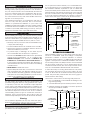
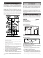
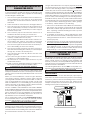
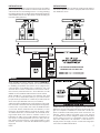
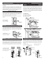
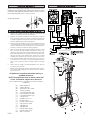
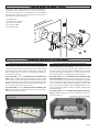
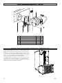
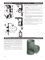
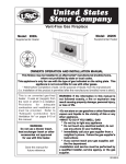
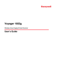
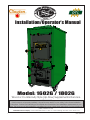
U USSC E STATES ST OV TED I N COMPANY Installation/Operator’s Manual Model: 1602G / 1802G Wood or Coal Gravity Style (Up-Flow) Supplemental Furnace SAFETY NOTICE: If this furnace is not properly installed, a house fire may result! For your safety, follow these installation instructions. Contact local building or fire officials about restrictions and installation requirements in your area. This furnace must be installed by a qualified technician. Keep these instructions for future reference. Safety Tested to UL 391 United States Stove Company • 227 Industrial Park Road, P.O. Box 151 • South Pittsburg, TN 37380 • www.usstove.com USSC 851768 rev 0 1 Thank You for your purchase of a U.S. Stove Wood/Coal Burning Gravity Style (Up-Flow) Furnace. Your decision to buy our Clayton Furnace was undoubtedly reached after much careful thought and consideration. We are very proud you chose this furnace and trust you will receive the comfort and economy that others realize when heating with a U.S. Stove product. Your dealer is important in your experience with the furnace not only with the purchase, but for recommendations for professional installation in your home. The qualified professional installer has been expertly trained in solid-fuel furnace installation to assure the safety and comfort for your family while saving you money. Trust your experienced installer. He is a specialist in this field. IMPORTANT Before installing and using your Clayton furnace, please read the following pages thoroughly and carefully. If you follow the instructions, your Clayton furnace will give you safe and more dependable service for years to come. • First step: Check your local codes. This installation must comply with their rulings. • Do Not install this furnace in a mobile home or trailer Do not place the furnace directly on a combustible floor. If you are placing it on a combustible floor, an approved fire retardant material, equivalent to 3/8” UL Listed millboard, should be placed under the unit. The material must extend at least 16 inches beyond the front of the unit and 8 inches on either side of the fuel loading door opening. It must also extend underneath the chimney connector and to each side of the connector by at least 2 inches. CLEARANCES COMBUSTIBLE WALL Model 1602 - 20” 1802 - 25” COMBUSTIBLE WALL INTRODUCTION (TOP VIEW) Model 1602 - 22” 1802 - 19” Model 1602 - 12” 1802 - 8” DO NOT store combustible or flammable materials or liquids near the furnace. REDUCED CLEARANCES • NEVER INSTALL outside the home. NFPA guidelines and most codes permit reduced clearances to combustible walls and ceilings if adequate protection is added. A common mistake is to assume that sheet metal, masonry, or millboard placed directly against a wall protects it. Materials installed in this manner actually provides very little protection. These materials are good heat conductors, so they will be almost as hot on their back side as they are on the exposed side. Therefore, the combustible wall behind is still a fire hazard. • Spend adequate time with your furnace to become well acquainted with the different settings and how each will affect its burning patterns. It is impossible to state just how each setting will affect your furnace because of the variations in each installation. A wall can be kept cool using these items but only if they are mounted and spaced out from the wall by an inch or two to allow free air circulation behind the protective panel. The protective panel should also have a gap between the floor and ceiling. • This furnace must be installed ONLY in the prescribed manner shown in illustrations 1, 2, or 3 under the Installation Examples in this manual. It is NEVER to be installed as a counter-flow or down-draft furnace, or in any manner wherein the heated air is directed in a downward flow into the home or toward to an existing central furnace. DISCLAIMER NOTICE The BTU ranges and heating capacity specifications are provided as a guide and in no way guarantee the output or capacity of this unit. The actual BTU output depends on the type of fuel being burned and its conditions, the thermostat setting, the draft adjustment and the chimney to which the unit is attached. The actual area that this unit will heat depends on factors such as the conditions of the building, heat loss, type of construction, amount of insulation, type of air movement, the location of the unit and more importantly the duct work and return air facility. Warning: Do not alter this appliance in any way other than specified in these instructions. Doing so may void your warranty. LOCATING YOUR FURNACE The furnace is to be installed maintaining the clearances specified in the following illustrations. 2 FLUE MINIMUM CLEARANCES TO A COMBUSTIBLE WALL CAUTION: • Always have a smoke or ionization detector and a CO detector installed in your home. • To prevent injury or damage, do not allow anyone who is unfamiliar with the furnace to operate it. Model 1602 - 15” 1802 - 28” Three rules to follow when constructing wall protectors: 1. Non-combustibility of all materials including mounting and supporting. 2. A well ventilated air space between protector and wall. 3. Sufficient strength and rigidity so that the protector and air space will be durable. 2” FROM CEILING CONSTRUCTING NON-COMBUSTIBLE WALLS PROTECTIVE COVERING AND ALL SUPPORTS MUST BE NON-COMBUSTIBLE 1” AIR SPACE 2” FROM FLOOR USSC CHIMNEY REQUIREMENTS A fireclay lined masonry or Class A 103HT All-Fuel Metal Insulated Chimney must be used in all airtight wood furnace installations. The minimum recommended flue size for the model 1602 is 6 inches, inside diameter and for the 1802, the recommended flue size is 8 inches, inside diameter. When making new chimney installations, always follow the chimney manufacturer’s instructions. If at all possible, use the factory built, class A 103HT chimney mentioned above. They are safer and perform better than traditional masonry chimneys. If a masonry chimney is a must, be certain it has a fire clay liner and that it is intact, clean and recently inspected. And remember, masonry chimneys are far more prone to the formation of hazardous creosote. CREOSOTE - FORMATION AND NEED FOR REMOVAL When wood is burned slowly, it produces tar and other organic vapors, which combine with expelled moisture to form creosote. The creosote vapors condense in the relatively cool chimney flue of a slow-burning fire. As a result, creosote residue accumulates on the flue lining. When ignited, this creosote makes an extremely hot fire. The chimney connector and chimney should be inspected at least twice monthly during the heating season to determine if a creosote build-up has occurred. If creosote has accumulated, it should be removed to reduce the risk of a chimney fire. SMOKE PIPE INSTALLATION Clearances to combustible materials (i.e. paneling, ceiling tile, sheet rock, plaster, draperies, casements or wood trim, etc.) will vary with the type of flue connection used. Be sure to maintain the specified clearances for your type of installation. TYPE OF FLUE REQUIRED CONNECTION CLEARANCE 24 Gauge or Heavier ...................................18” Single Wall Stainless Steel or Black Pipe Double Wall, Stainless Steel or.....................6” Model 1602 Double Wall, Black Pipe w/ 8” Model 1802 Stainless Steel Inner wall Class A 103HT All-Fuel or Equivalent . .........2” 1. The furnace should be the only heating using the chimney flue . One furnace per flue outlet. 2. A masonry chimney should have a tile or stainless steel liner. According to NFPA standards, single wall stove pipes can be within 9” of combustibles provided an approved fire retardant material covered with 28 gauge sheet metal, spaced out 1” on non-combustible spacers, is utilized. See illustration. 3. The masonry chimney should not have any missing mortar or loose bricks. 4. There should be no mortar or parts of the chimney blocking the chimney flue. 5. There should be a two inch clearance between any chimney (masonry or metal) and combustibles. (such as the house) 6. The chimney should extend at least 2 foot above the highest point of the house, or 2 foot above the point at which the chimney is 10 foot from the roof. 7. The chimney should be relatively straight and vertical. 8. The portion of an all-fuel metal chimney that extends above the roof should be well secured. 9. A masonry chimney should be built on footings and not attached to the house. 10.A rain cap, complete with an animal or bird screen, should be installed on top of the chimney. USSC When using a Class A or double wall flue pipe connection, follow the manufacturer’s instructions. When constructing a single wall smoke pipe, the following guidelines must be observed. 1. The connector pipe should be 24 gauge or heavier stainless steel or black pipe. 2. Secure all joints with three #8 screws. 3. If the connector pipe must pass through a wall, an approved insulated or ventilated thimble, at least three times the diameter of the smoke pipe must be used. (i.e. a 6” diameter smoke pipe needs an 18” thimble). 4. The connector pipe should never be used as a chimney. 3 IMPORTANT INFORMATION FOR ALL CONNECTOR PIPES The connector pipe must be constructed and installed so that it maintains clearances, keeps condensation and creosote within the pipe, and is capable of withstanding a 2100°F degree chimney fire. 1. The connector pipe should slant down toward the furnace a minimum of 1/4” to the foot. At no time should the pipe turn downward toward the chimney or run horizontal. 2. There should be no more than two 90 degree elbows. 3. The connector pipe should never be longer than six feet. If it is absolutely necessary to make a run of more than six feet (not recommended) use extra support brackets every 3 feet. 4. The connector pipe should never be reduced to a smaller size than flue opening on the furnace. 5. The connector pipe should not block the flue of the chimney or extend into it in any way. 6. A good airtight thimble should be used to hold the connector pipe in the chimney. It should be constructed so the connector pipe can be removed for cleaning. 7. The connector pipe should not leave the heated portion of the building to reach the chimney. 8. The connector pipe should not pass from one story to the next before entering the chimney, nor should it pass through any closed or enclosed space. 9. The connector pipe and any elbows must be of 24 gauge or greater. 10.The connector pipe should not be located near or in a walk way or well traveled area. 11. All male ends of connector pipe should run or point towards the furnace. 12.Install a cast iron adjustable damper in the first joint of the connector pipe, nearest to the flue collar. DAMPERS ON STOVE PIPES When burning coal, we recommend a Barometric Draft Damper be installed at a safe convenient place between chimney and your furnace preferably less than 3’ from the flue collar. When you have installed the connector pipe between your furnace and the chimney, tap the pipe hard with your fingernail. Remember the sound it makes - it will be a “ting” echoing inside the stove pipe. If later you tap and hear a muffled thud, you are building up soot in the pipe and should clean it. This pipe should be cleaned at least once or twice during the heating season. DO NOT CONNECT TWO HEATERS TO THE SAME CHIMNEY FLUE. The National Fire Prevention Association recommends that wood burning appliances vent into a separate flue from gas or oil furnaces. If such an installation is contemplated, first check with a local building inspector to find out if a separate flue for a wood burner is required. Use of a Barometric Draft Control (when burning wood) is recommended ONLY in the event your chimney creates excessive draft leading to an over-firing condition. Though United States Stove Company expressly Does Not recommend the use of its furnaces to be installed and/or used as a free-standing heater, it is possible to achieve a reasonably safe and functional installation IF certain standard procedures are followed. The following are guidelines only and are intended to enable the furnace user to obtain reasonable efficiency from his furnace, and with due respect to safety when installing as a “free-standing heater”. If installed correctly, and in accordance with the instructions found in this manual, your warm air furnace may be installed as a “space heater” within living quarters, cabins, garage, or workshop. Please adhere to the following: 1. The use of a cold air return and/or filter box is mandatory. This will not only increase your blower life and provide filtered air, it will also help prevent the blower or blowers from “capturing” heated air exiting from the top of the furnace heat outlets. 2. If installed as purchased , without directing the heat away from the furnace itself, it will simply sit and cycle, turning the blowers off and on. The thermostat may not function properly. 3. All larger furnaces (or those with multi-speed blowers) absolutely require BACK PRESSURE to prevent premature motor winding failure. If allowed to operate at high RPM (As in “FREE AIR” mode - no duct work or flow restrictions) the windings overheat, insulation melts and the motor simply burns up - not covered under warranty. CONNECTING HOT AIR DUCT TO FURNACE We strongly recommend that the hot air duct work be installed by a home heating specialist. If doing the installation yourself, before you decide which installation will best suit your needs, consult a qualified heating technician and follow his recommendations as to the safest and most efficient method of installation. The following illustrations are the ONLY acceptable configurations when installed with existing oil or gas furnaces. INSTALLATION EXAMPLES INSTALLATION #1 With this installation, a back draft damper (optional) is inserted into the heat run before the plenum of the existing furnace to prevent air from the existing furnace to blow back into the furnace when it is not in use. When a back damper is employed, it should be located as close to the existing furnace plenum as practical. HEATED AIR DISCHARGE The Clayton furnace is designed for use as a supplemental heating source. When used as a supplementary furnace, the 1602/1802 is connected in conjunction with an oil, gas, or electric furnace to the existing duct work which distributes the heated air into several rooms and/or areas. 4 USSC INSTALLATION #2 Extending the hot air duct from the furnace into the existing plenum will help direct the flow of air from the furnace as well as the flow in the existing furnace. Ducting entering the existing plenum at an angle (approximately 45 degrees) will facilitate air flow from the furnace while diverting air from the existing furnace. INSTALLATION #3 The baffle on this system should be made the full width of the furnace plenum in order to properly direct the air into the distribution ducts. THE PLENUM OPENINGS DIFFER BETWEEN THE 1602 AND 1802 MODEL 1602 - 13” x 18” Rectangular MODEL 1802 - 18” x 18” Rectangular RETURN AIR IS VERY IMPORTANT When installing a Clayton Furnace, return air MUST BE incorporated into the system. Return air can be provided by installing a separate duct system or by tying into the cold air return of an existing gas or oil furnace. The cold air return duct can be connected to the furnace with either a factory manufactured U. S. Stove filter box, model UFB908 or an equivalent fabricated from sheet metal. When installing a cold air return, the minimum size shall be a 16” x 20” or equivalent (320 sq. in.) in order to insure proper furnace performance. Failure to provide return air ducts of the specified size will void your warranty. NEGATIVE PRESSURE IN BASEMENT A filter should be installed in the cold air return. Furnace filters should be checked and cleaned/replaced regularly. COMBUSTION AIR If return air is not provided, the warm air distributed into your home will be restricted and the efficiency of the furnace is decreased. Without a return air system, warm air will be drawn into your basement, unnecessarily heating unused areas of the home. In extreme cases, if your basement or utility room is fairly airtight, the blowers on the furnace could depressurize the room and pull toxic flue gases from the furnace, a gas water heater, or gas furnace. The fumes could then be distributed throughout the house. All fires need air (specifically oxygen) to burn. Furnaces, fireplaces, and wood burning furnaces need enough oxygen for complete combustion of their fuels. The incomplete combustion that takes place when a furnace is “air starved” causes carbon monoxide (CO) to be formed in quantities that can be dangerous inside a well sealed house. Having a source of combustion air from outside the home will prevent “air starvation” of the furnace. A simple positive air supply can be constructed using dryer vent and a modified termination. USSC 5 FURNACE ASSEMBLY INSTRUCTIONS Unpack your Furnace and insure that there is no shipping damage. If damage exist, please contact your dealer immediately. Your Clayton Furnace will require some assembly before operation. All needed hardware and components for the following assemblies are included within the parts boxes inside the furnace and in the ash pan. Read and follow these instructions for proper furnace assembly. DOOR HANDLES Insert door handle into door. From rear side of door, place a 1/2” washer over the threaded part of the handle, then attach the lock nut. Tighten the nut, then back off 1/4 turn to allow free operation of the handle. Follow these same directions for the ash door handle assembly. SHAKER GRATE HANDLE Insert the Shaker Rod into the hole on the ash door frame as shown. Then attach the Shaker Bracket to the front of the furnace using two 1/4-20 x 3/4” Hex Bolts and two 1/420 Lock Nuts. Next, insert the shaker Rod into the bracket and attach to the shaker grate bar using the 1/4-20 x 1” Hex Bolt and a 1/4-20 Lock Nut. The bolt and nut retaining the shaker bar and rod should be left loose to allow free movement of the grates. (1) Shaker Rod (1) Shaker Bracket (1) 1/4-20 x 1” Hex Bolt (2) 1/4-20 x 3/4” Hex Bolt (3) 1/4-20 Lock Nut BRACKET (2) Door Handle (2) 1/2” Washer (2) 1/2” Lock Nut ASH DOOR SPIN DRAFT Screw the spin draft onto the 3/8” x 2-1/2” carriage bolt. Then screw the spin draft and bolt into the ash door allowing approximately 1/2” of the bolt to stick through the back side of the ash door. Secure the bolt in place with the 3/8”-16 lock nut. (1) Spin Draft (1) 3/8-16 Carriage Bolt (1) 3/8-16 Lock Nut FUEL & ASH DOOR LATCH With two 1/4-20 x 3/4 hex bolts each, attach the door latches to the door latch mounting brackets on the left side of the door frames as illustrated. The slots in the brackets and latches are for door seal adjustment. Make the proper adjustments, then tighten the nuts. The door’s gasket should be snug against the door frame on the furnace. (1) Feed Door Latch (1) Ash Door Latch (4) 1/4-20 x 3/4 Hex Bolt (4) 1/4-20 Kep Nut Feed Door Illustration Ash Door Illustration SMOKE CURTAIN Using two 1/4-20 x 1-1/4” Carriage bolts, the smoke curtain clips and two nuts, attach the smoke curtain in place above the Fuel Feed Door as shown below. After installation, the smoke curtain should swing freely back into the furnace. (1) Smoke Curtain (2) 1/4-20 x 1-1/4 Carriage Bolt (2) Smoke Curtain Clips (2) 1/4-20 Kep Nut 1/4-20 NUT SMOKE CURTAIN CLIP 1/4-20 x 1-1/4 CARRIAGE BOLT SMOKE CURTAIN NUT BOLT SMOKE CURTAIN CLIP SMOKE CURTAIN FRONT 6 USSC SPRING HANDLES WIRING DIAGRAM Attach the four(4) spring handles to the Feed/Ash Doors, Baffle Rod, and Shaker Rod by twisting the springs counterclockwise while applying pressure until you have screwed them approximately 3/4”-1” onto the rods. (4) Spring Handles DISTRIBUTION BLOWER & ACC. 1. Remove all contents and insure that all components are present for assembly. See the part list below 2. Begin by attaching the blowers to the unit. Insert a clip into each mounting hole in the furnace’s cabinet back. Be sure to install the gasket between the blower and cabinet back. Insert the eight bolts provided and tighten. 3. Mount the Honeywell limit control to the cabinet back. The conduit assembly should already be attached to the limit control, otherwise, do so then make the correct wiring connections to the limit control. See wiring diagram. 4. Next, mount the junction box and insulation using two of the #10 x 1/2 screws provided. Make a small slice in the 5 x 5 insulation to allow the wires from the draft blower to protrude, then Install it between the cabinet back and junction box, with the foil side to the cabinet back. Attach the conduit assembly from the limit control to the junction box as shown. 5. If not already installed, snap the rocker switch into the top of the junction box. Provide a 110 volt power supply and connect to the junction box with the cable clamp to the right side. 6. Attach the two longer conduit assemblies to the junction box and to each blower. 7. Before mounting the Fan Center, make all the wire connections per the wiring diagram, then attach the fan center to the junction box. All electrical connections should be done by a qualified electrician. NOTE: The extra brown wire on the fan center has no use. It should be capped off or removed. The conduit may be cut shorter to provide a cleaner installation. USSC (2) (2) (8) (8) (2) (1) (1) (1) (1) (1) (1) (1) (3) (1) (1) (1) (8) 800 CFM Blower Gasket, Blower Tinnerman Clip, 1/4-20 1/4-20 x 3/4 Bolt Conduit Assembly (5ft) Honeywell Limit Control Conduit Assembly (1ft) Junction Box Insulation (5” x 5”) Rocker Switch Romex Cable Clamp Fan Center Control 73B Wire Nut 74B Wire Nut Female Term. (blue) Female Term. (red) #10 x 1/2 Screw 7 FORCED DRAFT BLOWER - 69189 Using two 1/4-20 x 1” bolts and nuts, attach the draft blower adapter to the draft tube on the front of the furnace. Then mount and secure the draft blower to the adapter with the three 10-24 Kep nuts. Plug the blower into the outlet on the front of the furnace. (1) Draft Blower (1) Draft Blower Adapter (2) 1/4-20 x 1 Hex Bolt (2) 1/4-20 Lock Nut (3) 10-24 Kep Nut FIREBRICK AND BAFFLE REPLACEMENT FIREBOX BRICK REPLACEMENT BAFFLE/BRICK REPLACEMENT This furnace comes from the factory with the firebrick installed. However, if brick replacement is necessary, follow these instructions. Before furnace operation, remove the brick retaining strip. This piece is used during shipping to reduce brick damage. If baffle replacement is necessary, slide the baffle out until you can access the nuts thru the flue outlet. Once the nuts have been removed, slide the baffle off the rod and thru the opening in the firebrick. You may have to remove one of the firebrick to make baffle removal easier. For model 1602, there are 6 full brick and 1 half brick per side. Install the half brick first by putting the bottom of the brick in first and let it rest against the firebox side and fire grates. Then slide it to the rear. After that, install the #2, #3, #4, #5 & #6 brick, sliding the 6th brick forward to allow for the 7th brick. Repeat for opposite side. For model 1602, there are 4 full brick and 1 half brick in the top of the furnace. Install the brick by inserting one end of the brick angled upward and then allowing the opposite end to rest on the firebox lip. Lay the brick between the spacer and firebox back. Slide the baffle to the rear and let it rest on that half brick. After installing brick #2 in the front, install #3 and slide it under the baffle. Finally install bricks #4 and #5. For model 1802, there are 8 full brick and 1 half brick per side. Install the brick in the same manner as previously instructed for the model 1602. NOTE: Prior to operation, be sure to remove the brick retaining strips. 8 For model 1802, there are 6 full brick in the top of the furnace. Install the brick in the same manner as previously instructed above. USSC TESTING AND OPERATING PROCEDURES 6. The forced air draft cycles GENERAL FURNACE OPERATION on demand from the wall thermostat. Setting the U.S. Stove thermostat four degrees higher than your existing thermostat is recommended. In operation, the power draft blower will run until the U.S. Stove thermostat temperature setting is reached. The draft regulator on the forced air draft is preset at the factory and should require no adjustment. After installation of the furnace is complete, it is ready for operation. The Honeywell Limit Control, in conjunction with a wall thermostat, operates the distribution blowers and the draft blower on the front of the furnace. The limit control can be adjusted to your desired blower On/Off times. The factory settings are 100/150/200. The wall thermostat setting operates the ON time of the draft blower. If the temperature is below the setting on the wall thermostat, the draft blower will come on. (Recommended setting at 5 to 10 degrees higher than other heating thermostats.) The first two set points on the limit control operates the distribution blower(s). When the furnace plenum reaches the second set point on the limit control, the distribution blower(s) will come on. If the temperature falls to the first set point, the distribution blower(s) will shut-off. The rocker switch on the top of the junction box gives you the option to run one blower or two. If the switch is ON, both blowers will come on when the plenum reaches the set temperature. When the furnace reaches the third set point on the limit control, the draft blower will shut-off. The draft blower will come back on if the temperature falls below the setting on the wall thermostat. TESTING 1. Check the draft blower by turning the room thermostat up high enough so that the draft blower turns on. Then lower the thermostat setting until you hear it shut off. 2. Use a sheet of newspaper to test your draft by placing it inside the furnace and lighting it. With completion of the tests above, you are ready to light the furnace. Follow the operating steps. STARTING A WOOD FIRE Using Forced Air Draft CAUTION: Never use gasoline, gasoline-type lantern fuel, kerosene, charcoal lighter fluid, or similar liquids to start or “freshen up” a fire in the furnace. Keep all such liquids well away from the furnace while it is in use. 1. Open spin draft cap on ash door. 2. Pull the slide baffle rod to the front position. 3. Open the fuel load door and light fire using kindling and several sheets of newspaper, then close the furnace door. The furnace door should remain closed for 5 to 10 minutes in order to establish the fire. If the fire has established, you are ready to load the furnace. CAUTION: To prevent flame and smoke spillage, the slide baffle must be pulled out and the fuel door must be cracked for ten seconds before being fully opened. Do not over fire your furnace! After you have become familiar with its operating, you should know how much wood to use. 4. Load the furnace, close the load door and push the slide Baffle rod to rear. CAUTION: To avoid excessive temperatures, do not operate with fuel door or ash pan open. STARTING A COAL FIRE If you burn coal, a forced air draft is required Shut off FAD when fuel door is open Open smoke pipe damper all the way. Open all draft controls on your 1602/1802. Pull the slide baffle forward. Place about 10-15 lb. of coal in on the shaker grates. It should come up to about half of the first firebrick level. Place crumpled paper over the coal and crisscross a couple handfuls of dry kindling wood 3/4” in thickness on top of paper. Ignite the paper and close loading door. Wait about 30 minutes until coal fire is established before adding more coal. NOTE: NEVER load coal over the level of firebrick. Close by-pass damper and set all draft controls to your own needs. It may take 3 to 4 coal fires to determine how your local coal and the Clayton Furnace reacts together. Adjusts drafts accordingly. Loading with a good bed of coals in the morning - Open by-pass damper. 1. In normal shaking, only rock the grates a small amount to sift ash through. Do not agitate the fire bed too often. This practice will waste coal. If glowing coal is visible in the ash pan, you have shaken to much. 2. Remove all ashes every day from ash pit. CAUTION: Ashes should be placed in a metal container with a tight fitting lid. The closed container of ashes should be placed on a non-combustible floor or on the ground well away from all combustible materials pending final disposal. If the ashes are disposed of by burial in soil or otherwise locally dispersed, they should be retained in the closed container until all coals have thoroughly cooled. 3. With your poker, push hot burning embers to the rear of the unit and add green coal in front. NEVER load over height of firebrick. This can result in damage to your furnace and home. 4. Close by-pass damper. Too much draft air will cause clinkering of coal and will waste heat up the chimney. Shut draft down to as low a point as you can and still heat your home. 1. NOTE: Never stand in front of loading door when opening it. Stand to the side. 2. NEVER completely cover the live fire with fresh coal. Always leave a generous area of glowing coal at the top of the fire and at the rear. 3. Always keep the ash pit clean. 5. Close the spin draft cap on ash door, leaving it cracked about the diameter of a dime. USSC 9 If the fire goes out or does not hold overnight, look for: 1. Poor draft. 2. Incorrect damper settings. 3. Improper firing methods for coal being used. 4. More combustion air needed. 5. Coal not sized to the furnace. We recommend 1” to 3” diameter pieces of coal. 6. Ashes, if allowed to accumulate in the ash pit, will not allow the passage of required air for combustion. Keep ash pit clean. 7. This furnace is not to be used with an automatic stoker unless so certified. There are ONLY two types of coal allowed for use in this furnace: Bituminous Coal (soft coal) and Anthracite Coal (hard coal). NEVER USE Cannel (or Channel) coal or Brown (Lignite) Coal. See our Bulletin RC454 at the rear of this manual for the best information available on burning coal. OPERATING NOTES Do not over draft the furnace! It is designed to operate at .06 inches of water column and must be set with a draft gauge to maintain a steady draft. (Barometric Damper recommended.) Do not allow ashes to build up higher than 2” above grates. Never allow the ashes in the ash pan touch the grate section. REMOVE ASHES FREQUENTLY! Be extremely careful when removing furnace ash pan; it can get very hot. With new steel, there is a small amount of oil or dirt on the metal. You may smell an odor. This is normal during the first operation. You may want to assemble the furnace out of doors and build a small fire in it to “burn off” this dirt and oil before installing the unit. The furnace is designed to burn air dried wood and coal at a predetermined firing rate. Over firing could result in damage to the heat exchanger and cause dangerous operation. Over firing occurs when the ash door is left open during operation or a highly volatile fuel, i.e. large amounts of small kindling, is used. If any portion of the connector pipe glows orange or red, you are in an over-firing situation. Close all dampers. Inspect and clean your chimney and stove pipe regularly. In event of chimney fire, shut all draft controls and call your fire department immediately. Alert everyone in the house. If the fire is still burning vigorously, throw baking soda into firebox or discharge a fire extinguisher into the firebox. After chimney fire is over, completely inspect system for damage before further use. NEVER throw water on the fire or at the furnace, as rapidly expanding steam could result in a severe scalding. Slow fires: It is not recommended burning the Clayton furnace any more than necessary early in the fall and late spring, as you cannot keep the firebox hot enough (without overheating your home) to burn gases. Slow fires can cause excessive creosote build-up in smoke pipe, chimney and firebox. Wood should be placed directly onto the cast iron shaker grate of the Clayton furnace. Do not use additional grates and/or irons. In the event of a power failure, you may operate the 1602/1802 furnace provided the following instructions are followed: 1. Any air filter should be removed. 2. Observe the furnace operation closely and often till power is restored. Do not burn garbage, plastics, gasoline, drain oil or other flammable liquids. Plastics, when burned, form hydrofluoric and hydrochloric acids which will damage and destroy your furnace pipe and chimney. The burning of trash or oil can result in an extremely hot fire and is sometimes a cause of chimney fires. NEVER BURN GREEN WOOD OR TIRES. Do not store fuel or other combustible material within marked installation clearances. NOTE: For further information on using your furnace safely, obtain a copy of the National Fire Protection Association publication “Using Coal and Wood Stoves Safely.” NFPA NO. NW-8-1974. The address of the NFPA is 470 Atlantic Ave., Boston, Massachusetts 02210. THIS IS A WOOD AND COAL BURNING FURNACE AND SHOULD NOT BE ALTERED IN ANY WAY! DOING SO WILL VOID YOUR WARRANTY! When tending the firebox always pull the baffle slide rod out prior to opening load door. Open load door slowly to avoid a “flash back”. After closing load door, push the baffle slide rod to the rear. Equip your home with fire extinguishers and smoke detectors appropriately located. Inspect air filters regularly. The air filter in the filter box should be changed at least every 30 days. Oil motor on forced air draft every 90 days with a few drops of 30 wt. oil. The distribution blower motors may be one of two types. If the motor has sealed bearings, no oiling is required. If the motor is equipped with fill holes, the motor should be oiled every 90 days with several drops of 30 wt. oil. Check the fit on the load door. It must fit tightly. If it does not, check for deterioration or wear of the ceramic rope seal. Replace defective seals. 10 USSC TROUBLE SHOOTING AND PROBLEM SOLVING 1. Problem: 4. Problem: Smoke puffs from furnace Distribution blower vibrating Solution: Solution: A. Check chimney draft. Check for blocked chimney or flue pipe. Use mirror to check chimney clearance. A. Tighten blower wheel to motor shaft. B. Check for bad fan bearings. B. Check ash pit — if it is too full, empty. 5. Problem: C. Make sure furnace room is not too airtight. Distribution blower continues to run or will not run D. Make sure all of chimney mortar connections are airtight. Solution: E. Check ash drawer. Make sure it’s airtight. F. Check chimney for possible down-draft caused by taller surrounding trees or objects. Correct with proper chimney vent cap. G. Check the possibility of a cold chimney forcing cool gases backward. Remedied by properly insulating chimney with non-combustible liner — non-combustible insulation. H. Fuel may be too green. I. Make sure no other fuel burning devices are connected to the chimney impairing the draft. J. Check chimney draft, it should be .06 inches of water column. This service is provided by a certified chimney sweep. 2. Problem: Inadequate heat being delivered to your home Solution: A. Check home insulation — is it adequate? B. Check hook-up to furnace — is it installed correctly? C. Cool air inlet may be inadequate or furnace room too airtight. D. Your wood fuel may be too low grade. Hardwoods are recommended. E. Make sure your hot air duct (and other duct work) is airtight. F. If furnace room is warm but your home isn’t, check back draft dampers. G. Is air to the blower available? 3. Problem: Excess smoke or flames coming out door when refueling Solution: A. Wait 15 seconds and open door SLOWLY — then refuel. A. Check fan limit or heat sensor and cable. B. Check to see that blower is properly wired. (See Wiring and Assembly Instructions). C. Check fuse box or power source. D. Check power supply. 6. Problem: Draft blower continues to run or will not run Solution: A. Check wiring. B. Check thermostat or thermostat wire for short. C. Make sure temperature is calling for heat. 7. Problem: Odor from first fire Solution: A. The odor from new steel should disappear in a few hours. B. If the odor remains, call you dealer immediately. A bad weld can cause a fume leak. 8. Problem: Excessive Creosote Solution: A. Check the grade of wood you are burning. B. Make sure your unit is serviced by its own proper chimney. C. Check length of flue pipe and its connections. D. Make sure you are burning the smallest, hottest fire to adequately heat your home. E. Also see Solutions to Problem one. 9. Problem: If the fire goes out or does not hold over night Solution: A. Poor Draft. B. Check length of flue pipe to chimney. Your unit should be within six (6) feet of your chimney. B. Incorrect damper settings. C. Make sure chimney cap is not too close to the top of the chimney. D. More combustion air needed. D. Check chimney draft — make sure chimney flue pipe is clean and chimney is of adequate height. C. Improper firing methods if burning coal. E. Coal not sized to the furnace. We recommend 1” to 3” diameter pieces of coal. E. Make sure you’re not suffocating the fire with excessive amounts of unburned wood. F. Ashes, if allowed to accumulate in the ash pit, will not allow passage of the required air for combustion. Keep ash pit clean. F. Slide baffle should be pulled out prior to load door opening. G. This furnace is not to be used with an automatic stoker unless so certified. USSC 11 PARTS DIAGRAM 23 35 34 28 29 30 34 22 36 33 21 20 3 18 19 16 4 17 3 2 1 27 25 26 37 24 9 3 8 7 10 6 14 15 16 17 2 5 3 32 31 13 12 11 12 USSC PARTS DIAGRAM AND LIST Key Description Part # Qty Key 1 Feed Door Assy. (w/Rope Gasket) 69091 1 2 36 P Front Filler Front Filler - 1800 23817 24190 1 37 P Draft Cover Draft Cover - 1800 23818 24508 1 38 Room Blower - 800 CFM 80530 2 39 Blower Gasket 88127 2 40 Tinnerman Clip, 1/4-20 83340 8 41 Bolt, 1/4-20 x 3/4 83339 8 42 Conduit Assembly (5ft) 69578 2 43 Honeywell Limit Control 80145 1 44 Conduit Assembly (1ft) 68859 1 45 Junction Box 25625 1 46 Insulation (5” x 5”) 25626 1 47 Rocker Switch C42373 1 48 Romex Cable Clamp 80362 1 49 Fan Center Control 80130 1 50 Water Coil Access Cover 23819 1 Door Handle 24179 2 N/S Lock Nut, 1/2-13 83444 2 N/S Washer 83835 2 3 Spring Handle 89574 4 4 Feed Door Latch 23786 1 5 Ash Door Assy. (w/Rope Gasket) 68880 1 6 Draft Cap 23859 1 7 Ash Door Latch 23823 1 C21399 4 N/S Hinge Pin, 5/16” x 1” 8 Shaker Handle 69005 1 9 Bracket, Shaker Handle 24204 1 10 P Ash Pan Ash Pan - 1800 68882 68919 1 11 P Grate Retainer Grate Retainer - 1800 12 Shaker Bar 891341 1 13 P Shaker Grate Section Shaker Grate Section - 1800 40314 ............. 5 14 P Back Liner Back Liner - 1800 40313 40339 15 P Front Liner Front Liner - 1800 40344 40338 16 P Full Firebrick (4-1/2 wide x 9 tall x 1-1/4 thick) .............................................................................. 89066 ............. 16 22 17 P Half Firebrick (2-1/4 wide x 9 tall x 1-1/4 thick) .............................................................................. 891414 ............. 2 18 Slide Baffle 19 P Baffle Rod Baffle Rod - 1800 86603 86607 20 Lock Nut, 1/2-13 83444 2 21 Gasket, Flue Collar 88032 1 22 Flue Collar 40246 1 23 P Flue Collar Ring Flue Collar Ring - 1800 24 Smoke Curtain 23800 1 25 Smoke Door Clip 23787 2 26 Carriage Bolt, 1/4-20 x 1-1/4 Long 83445 2 27 Kep Nut, 1/4-20 83250 2 28 P Cabinet Side, Left Cabinet Side, Front Left - 1800 68821 68962 1 1 29 P Insulation, Side Insulation, Side - 1800 C98771 23977 2 2 30 Insulation Retainer 83884 41 31 P Cabinet Side, Right Cabinet Side, Right - 1800 68822 68961 1 N/S Cabinet Side, Back - 1800 69002 2 32 Receptacle, Snap-In 80351 1 33 P Cabinet Back Cabinet Back - 1800 69573 69613 1 34 P Insulation, Panel Insulation, Back - 1800 C98871 23978 2 P Insulation, Top - 1800 35 P Cabinet Top Cabinet Top - 1800 USSC 40312 40337 1 2 7 1 1 24231 22761 23958 2 1 1 1 1 Part # Qty 1 1 N/S = Not Shown P = Items designated for model 1800 IMPORTANT NOTE: When ordering repair parts, a color code (G) should be placed after the part number of any part that is painted. 46 47 3 45 1 1 Description 48 1 43 1 44 1 50 49 42 40 39 38 41 2 23979 2 69088 68964 1 1 13 PARTS DIAGRAMS AND LISTS - 69189 1 2 4 Key 3 5 Description Part # Qty 1 Drqft Blower Assembly 69190 1 2 FAD Bracket 69192 1 3 Bolt, 1/4-20 x 1” 83379 2 4 Lock Nut, 1/4-20 83261 2 5 Kep Nut, 10-24 83244 3 UFB908 COLD AIR RETURN / FILTER BOX - OPTIONAL KIT As mentioned earlier in this manual, a cold air return and/ or filter box should be incorporated into your furnace installation. A cold air return or filter box will increase the life of your blowers and offer filtered distribution air for your home. U.S. Stove offers the model UFB908 as an option and can be purchased from your local dealer. The UFB908 utilizes a standard 16” x 20” filter that can be purchased from your local dealer or any hardware/duct work supply store. When installing a UFB908, follow the installation instructions supplied with the kit. 14 USSC DOMESTIC HOT WATER COIL KIT - OPTIONAL This Furnace will accept the installation of a Domestic Hot Water Coil Kit. The U.S. Stove kit is a 1124 Water Coil and it may be purchased from your local dealer. 2 1. Remove the access panel on the rear of the furnace enclosure. 2. With a utility knife, cut away a section of the insulation (if equipped) directly behind the access panel. 1 3. Remove the cover plate from the rear of the furnace firebox. ACCESS PANEL 4. Place one nut on each end of the water coil and thread each nut up to the end of the threads on the coil. 5. Insert the coil through the holes from the inside of the firebox. Install a gasket, washer and nut onto each end of the water coil. Tighten the nuts down securely to insure an air tight seal. 3 The installation is now ready to be plumbed to your existing hot water system. Choose one of the three methods described in the Hot Water Coil instructions. 6. Remove knockouts from the access panel and re-attach to the furnace enclosure. REAR WALL OF FIREBOX 5 Have a qualified plumber connect your domestic hot water pipe to the coil with the appropriate fittings. 4 DOMESTIC HOT WATER COIL 1. NUT 2. WASHER 3. GASKET TURN INSIDE NUTS UP TO END OF THREADS 6 DR6 - 6” DRAFT REGULATOR KIT - OPTIONAL KIT In the unlikely event that your furnace “overfires” (a condition evidenced by elbows, stove pipes, and connectors glowing red in appearance or otherwise discoloring), then your installation is subject to excessive draft created by either a chimney too tall or too great in diameter in conjunction with its height, or some other factor of an indeterminate cause. In this event, you should install a barometric draft regulator. Such installation will preclude any over-firing and/or any hazardous consequences of potential overfiring. Barometric draft regulators are generally available where you purchased your stove or may be ordered directly from United States Stove Company at a nominal charge. USSC 15 BULLETIN RC454 A GUIDE TO BURNING COAL IN YOUR FURNACE Furnaces that are capable of burning coal usually will burn both Bituminous and Anthracite coal. Anthracite is perhaps the best coal fuel because of its long even burn time, high heat output, and cleanliness which make it a good choice for the home. However, keep in mind it is a much more difficult fuel to use, requires more care and patience, is not so widely available, and is usually much more expensive than Bituminous. SIZE OF COAL: Most sizes of Bituminous Coal will work in a coal furnace; for best results we recommend large “nut” coal to small “egg” coal (1-3/4” diameter to 4” diameter). When burning Anthracite, use “egg” or “broken” with sizes between 2-5/16” thru 4-3/8”. Note that it is important to the long life of your stove to buy coal which has been sized and cleaned. Cleaning insures removal of rocks and other minerals. Never use coal smaller than 1” or larger than 5” in diameter. Small sized coal will smother the fire. Too large a size of coal will not burn well. STOVE OPERATION: All coal fires should be started with wood which will allow the fire to get hot enough to ignite the coal. The best ignition fires utilize dry pine or other resinous soft woods as kindling, with hard wood (oak, hickory, ash) added to increase the heat prior to addition of the coal. Before starting the fire, open the stove pipe damper (if epuipped), turn the thermostat to high, open the ash pit door and feed door, place newspaper and finely split kindling on the grate, light the paper, add larger hard wood after the kindling is burning brightly. CAUTION: Never use gasoline, lantern fuel, kerosene, charcoal lighter fluid, or other flammable liquids to start or freshen up a fire in any heater. Place the larger pieces of wood on the fire so that they are slightly separated and form a level for the addition of coal. It will take 10 to 20 minutes before this wood is thoroughly ignited. Adding coal too soon will cut the air supply and smother the fire. orange or yellow and produce quite a bit of smoke. As the gases burn off the flames become shorter, change color and produce less smoke. Once the fire is WELL ESTABLISHED add coal to the center of the firebox forming the cone. Burning in this fashion allows heat to drive off the volatile gases, and turbulence created increases the burn efficiency. There will have to be some experimenting with the individual setup as no two chimney’s or installations are going to be the same. Just remember to allow enough air to enter the firebox and keep the stove pipe damper open so that volatiles are properly burned. Before refueling, take the time to break up the cone a little with a poker, especially if it has caked over or formed a crust. But, be careful not to mix the coal as this increases the chances of forming clinkers. When shaking the grate(s) be gentle. Just a few short movements - a couple of “cranks” - is better than a lot of agitation. The objective is to remove a small amount of the ashes without disturbing the fire. Stop when you see a glow in the ashes or the first red coals fall into the ash pan. Excessive shaking wastes fuel and can expose the grate(s) to very high temperatures which can cause warpage or burnout. For overnight operation (long duration burn time) shake the fire and add coal, retaining the center cone. Once the volatiles are burned off, close the feed door and adjust the stove pipe damper, if epuipped. Then adjust the thermostat to the desired heat level. More MAINTENANCE will be needed with bituminous coal than with anthracite coal as more soot will collect on heating surfaces and in pipes, requiring more frequent cleaning. ANTHRACITE: BURNING BITUMINOUS: Add a thin layer of coal (preferably smaller chunks) to the wood fire, being careful not to disturb it too much or cut off the draft. Then, add a second heavier layer after the coal is ignited and burning well. If necessary, add a third layer to bring the coal up to the top of the front liner (not above!). Be sure to close the ash door. Once your kindling and wood fire has produced a bed of well established coals, start adding coal in layers allowing each to ignite before adding more. Bituminous has a high volatile content and, as a result, should be fired with the “conical method” - with the highest portion of your fire bed in the center of the firebox. The first flames will be long and generally Before adding further fuel, be sure to leave a red spot of glowing coals in the center of the firebox to insure that the fire has not been smothered and to help ignite the gases given off by the new charge. A deep charge will give a more even heat and a longer fire, but it may take one to two hours before the whole bed is fully ignited. 16 USSC BULLETIN RC454 A GUIDE TO BURNING COAL IN YOUR FURNACE When the fire is well established and the room is becoming warm, partially close the dampers. Some experimenting will have to take place with each particular setting of all dampers and controls as the chimney provides the draft necessary to not only exhaust the smoke, but to pull combustion air into the heater as well - and no two chimney’s perform the same. Under ideal draft conditions, one should be able to turn the secondary air supply below the feed door (some models) to a near closed position but leave the ash pit damper at least partially open to prevent the fire from going out. Adjust the stove pipe damper to reduce the draft on the fire. With anthracite there will be short blue flames above the coal, except when the fire is started or a new charge is added. If, however, there is no flame then the fire needs more air from the bottom (unless it is near the end of its burn cycle and needs to be recharged). Only when the coal is burned down to half its original depth it is time to add fresh coal. When doing so, open the stove pipe damper and turn the thermostat damper to high, which will allow the fire to burn off any accumulated gases. Open the feed door, and with a small rake, hoe, or hooked poker pull the glowing coals to the front of the firebox. Try not to disturb the fire too much. Next, add a fresh charge to the back being careful not to seal off the top. Close the feed door, but leave the spin damper (or thermostat) open for a few minutes until the volatile gases have burned off. It is not necessary to shake down the ashes each time you refuel the furnace. Experience will be your best teacher. USSC BANKING THE FIRE: For extended operation, such as overnight, the fire will need to be banked. To do so heap coal up along the sides and back of the firebox so that the fire gradually burns it over a longer period of time. The intensity of the fire will also be reduced without letting it go out. Follow the same procedure as for refueling. If possible, avoid shaking, as a heavier layer of ash will help reduce the intensity of the fire during this time. After loading, let the fire establish itself for about 30 minutes. Then close your damper and automatic control to the point where the house does not become too cold. It is important that you begin banking early enough before retiring or leaving that you can make necessary adjustments after the fire is well established. To revive a coal fire that is almost out, (1) open the ash door and stove pipe damper and close the spin damper under the door to get a good draft through the grate. (2) place a thin layer of dry coal over the entire top of the fire. DO NOT POKE OR SHAKE THE FIRE AT THIS TIME! (3) after the fresh coal has become well ignited shake the grate (just a little), refuel. DO NOT burn coke, charcoal, high volatile bituminous coal, sub bituminous, lignite or cannel coal (sometimes called channel coal or candle coal). NEVER burn wax or chemically impregnated sawdust logs - their intended use is for fireplaces only. NEVER fill the stove or furnace above the firebrick or cast iron liner. 17 NOTES 18 USSC NOTES USSC 19 HOW TO ORDER REPAIR PARTS This manual will help you obtain efficient, dependable service from the furnace, and enable you to order repair parts correctly. Keep this manual in a safe place for future reference. When placing an order or for warranty claims, please provide the following information found on the Certification Plate located below the ash door. PART NUMBER PART DESCRIPTION MODEL NUMBER - 1602 / 1802 SERIAL NUMBER______________ United States Stove Company 227 Industrial Park Road P.O. Box 151 South Pittsburg, TN 37380 (423) 837-2100 Customer Service: (800)-750-2723 • Repair Parts: (888) 299-1440 20 USSC