1
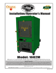
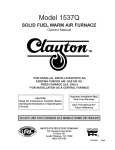
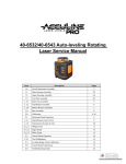
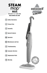
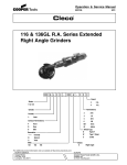
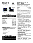
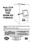
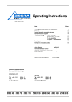
UNITED S
TATES
ST
STOVE C
OMP
ANY
COMP
OMPANY
K ee
ping North America W arm
eeping
Since 1869
MODEL: 1600M
WOOD and COAL FURNACE
SAFETY NOTICE: IF THIS FURNACE IS NOT PROPERLY INSTALLED, A HOUSE
FIRE MAY RESULT. FOR YOUR SAFETY, FOLLOW THE INSTALLATION DIRECTIONS.
CONTACT LOCAL BUILDING OR FIRE OFFICIALS ABOUT RESTRICTIONS AND
INSTALLATION REQUIREMENTS IN YOUR AREA. REFER TO MARKINGS ON
APPLIANCE FOR ADDITIONAL INFORMATION.
Installation/Operator's Manual #851547A
1
INTRODUCTION
CLEARANCES
Thank you for your purchase of a U.S. Stove Wood and Coal
burning furnace. Your decision to buy our Clayton Furnace was
undoubtedly reached after much careful thought and consideration. We are very proud you chose the U.S. Stove furnace and trust
you will receive the comfort and economy that others realize
when heating with a U.S. Stove product.
Your dealer is important in your experience with the Furnace not
only in your purchase, but in his recommendations for professional installation in your home. The qualified professional
installer (as recommended by your dealer) has been expertly
trained in solid-fuel furnace installation to assure the safety and
comfort for your family while saving you money. Trust your
experienced installer. He is a specialist in his field.
FLAMMABLE WALL
20"
15"
(TOP VIEW)
22"
FLUE
12"
IMPORTANT
Before installing and using your Clayton Furnace, please read
the following pages thoroughly and carefully. If you follow the
instructions, your Clayton furnace will give you safe and more
dependable service in the years to come.
MINIMUM
CLEARANCE TO
FLAMMABLE WALLS
CAUTION: Do not
store combustible or
flammable material
near furnace.
REDUCED CLEARANCES
NFPA guidelines and most codes permit reduced clearances to
combustible walls and ceilings if adequate protection is added.
A common mistake is to assume that sheet metal, masonry, or
millboard placed directly against a wall protects it. Materials
installed in this manner give very little protection. These materials
are good heat conductors, so they will be almost as hot on their
back side as they are on the exposed side. Therefore, the
combustible wall behind is still a fire hazard.
A wall can be kept cool using these items but only if they're
mounted and spaced out from the wall by an inch or two to allow
free circulation of room air behind the protective panel. The
protective panel should start within a few inches of floor level.
The three rules to follow when constructing wall protectors:
1. Non-combustibility of all materials including mounting
or supporting.
2. A well ventilated air space between protector or wall.
3. Sufficient strength and rigidity so that the protector and
air space will be durable.
First step; check your local codes. This installation must
comply with their rulings.
Do not install this furnace in a mobile home or trailer.
Always have a smoke or ionization detector and a CO
detector installed in your home.
To prevent injury or damage, do not allow anyone who is
unfamiliar with the furnace to operate it.
Spend some time with your furnace to become well
acquainted with different settings and how each will
affect its burning patterns. It is impossible to state just
how each setting will affect your furnace because of
the variations in each installation.
DISCLAIMER NOTICE
The BTU ranges and heating capacity specifications are provided as a guide only and in no way guarantee the output or
capacity of the units. The actual BTU output depends on the type
of fuel being burned and its conditions, the thermostat setting, the
draft adjustment and the chimney to which the unit is attached.
The actual area that the unit will heat depends on factors such as
the conditions of the building, heat loss, type of construction,
amount of insulation, type of air movement, and the location of the
unit, and more importantly, your duct work and return air facility.
2" FROM CEILING
CONSTRUCTING
NON-FLAMMABLE
WALLS
WARNING:
Do not alter this appliance in any way. Doing so may void
your warranty.
PROTECTIVE COVERING
AND ALL SUPPORTS MUST
BE NON-COMBUSTIBLE.
1" AIR SPACE
These instructions comply with CAN/CSA-B365
2" FROM FLOOR
LOCATING YOUR FURNACE
CHIMNEY REQUIREMENTS
The furnace is to be installed maintaining clearances as shown
in illustration.
Do not place the furnace directly on a combustible floor. If you're
placing it on a combustible floor, an approved fire retardant
material equivalent to 3/8" UL Listed millboard should be placed
under the furnace. The material must extend at least 16" in front
of and 8" on either side of the fuel-loading and ash-removal doors,
and underneath the chimney connector and extending at least 2"
on either side of the chimney connector.
A fireclay lined masonry or Class A 103HT All-Fuel Metal Insulated Chimney must be used in all airtight wood furnace installations. The minimum recommended flue size for the U.S. Stove
Clayton Furnace is 6" (inside diameter) for round flues, and 7" x
7" for square flues. When making new chimney installations,
always follow the chimney manufacturers instructions.
2
NOTE: Type of chimney: Class A All-Fuel UL 103HT
TOP OF CHIMNEY MUST
BE 2 FT. ABOVE HIGHEST
POINT OF ROOF WITHIN
10 FEET
on the flue lining. When ignited, this creosote makes an extremely
hot fire.
The chimney connector and chimney should be inspected at
least twice monthly during the heating season to determine if a
creosote build-up has occurred. If creosote has accumulated, it
should be removed to reduce the risk of a chimney fire.
CAP SHOULD HELP
PREVENT DOWNDRAFT
WHILE STILL PROVIDING
ADEQUATE EXHAUST.
SMOKE PIPE INSTALLATION
2 FT.
MINIMUMS
3 FT.
MINIMUM
MINIMAL 3 FT.
FROM TOP OF
CHIMNEY TO POINT
AT WHICH IT PASSES
THROUGH THE ROOF.
CHIMNEY FLUE
SHOULD BE
CONSTANT DIAMETER
THROUGHOUT ITS
ENTIRE HEIGHT.
APPROVED
CHIMNEY
Clearances to combustible materials (i.e. paneling, ceiling tile,
sheet rock, plaster, draperies, casements or wood trim, etc.)
will vary with the type of flue connection used. Be sure to
maintain the specified clearances for your type of installation.
TYPE OF FLUE
REQUIRED
CONNECTION
CLEARANCE
24 Gauge or Heavier
18"
Single Wall Stainless Steel
or Black Pipe
Double Wall Stainless Steel
6"
RECOMMENDED
MINIMAL
20 FT. HEIGHT
CHIMNEY FLUE
MUST BE AS
LARGE OR 20%
LARGER THAN
FURNACE FLUE
PIPE
Class A 103HT All-Fuel or Equivalent
2"
COMBUSTIBLES
SMOKE PIPE
CLEANOUT DOOR
SHOULD HAVE
AIRTIGHT FIT. DO
NOT LEAVE OPEN
WHEN FURNACE IS
IN OPERATION.
CHIMNEY THIMBLE SHOULD BE
CONSTRUCTED OF FIRE CLAY, AND
SHOULD FIT TIGHTLY TO FLUE PIPE.
According to NFPA standards, single wall stove pipes can be
within 9" of combustibles provided an approved fire retardant
material covered with 28 gauge sheet metal, spaced out 1" on
non-combustible spacers, is utilized. See illustration.
1. The furnace should be the only heating appliance using
a chimney flue. One furnace per flue.
2. A masonry chimney should have a tile or stainless steel
liner.
3. The masonry chimney should not have any missing
mortar or loose bricks.
4. There should be no mortar or parts of the chimney
blocking the chimney flue.
5. There should be a two inch clearance between any
chimney (masonry or metal) and combustibles (such
as the house).
6. The chimney should extend at least 2' above the
highest point of the house, or 2' above the point at
which the chimney is 10' from the roof.
7. The chimney should be relatively straight and vertical.
8. The portion of an all-fuel metal chimney that extends
above the roof should be well secured.
9. A masonry chimney should be built on footings and not
attached to the house.
10. A rain cap, complete with an animal or bird screen,
should be installed on top of the chimney.
18"
9"
18"
CEILING OR WALL
When using a Class A or double wall flue pipe connection,
follow the manufacturer's instructions.
When constructing a single wall smoke pipe, the following
guidelines must be observed.
1. The connector pipe should be 24 gauge or heavier
stainless steel or black pipe.
2. Secure all joints with three #8 screws.
3. If the connector pipe must pass through a wall, an approved insulated or ventilated thimble, at least three
times the diameter of the smoke pipe must be used. (i.e.
a 6" diameter smoke pipe needs an 18" thimble).
CREOSOTE — FORMATION AND NEED
FOR REMOVAL
4. The connector pipe should never be used as a chimney.
IMPORTANT INFORMATION FOR
ALL CONNECTOR PIPES
When wood is burned slowly, it produces tar and other organic
vapors, which combine with expelled moisture to form creosote.
The creosote vapors condense in the relatively cool chimney flue
of a slow-burning fire. As a result, creosote residue accumulates
The connector pipe must be constructed and installed so that it
3
maintains clearances, keeps condensation and creosote within
the pipe, and is capable of withstanding a two to three thousand
degree chimney fire.
1. The connector pipe should slant down toward the
furnace a minimum of 1/4" to the foot. At no time should
the pipe turn downward toward the chimney or run
horizontal.
HEATED AIR DISCHARGE
The Clayton furnace is designed for use as a supplemental
heating source. When used as a supplementary furnace, the
1600M is connected in conjunction with an oil, gas, or electric
furnace to the existing duct work which distributes the heated air
into several rooms and/or areas.
Though United States Stove Company expressly Does Not
recommend the use of its furnaces to be installed and/or used as
a free-standing heater, it is possible to achieve a reasonably safe
and functional installation IF certain standard procedures are
followed. The following are guidlines only and are intended to
enable the furnace user to obtain resonable efficiency from his
furnace, and with due respect to safety when installing as a "freestanding heater". If installed correctly, and in accordance with
the instructions found in this manual, your warm air furnace may
be installed as a "space heater" within living quarters, cabins,
garage, or workshop. Please adhere to the following:
2. There should be no more than two 90 degree elbows.
3. The connector pipe should never be longer than six
feet. If it is absolutely necessary to make a run of more
than six feet (not recommended) use extra support
brackets every 3 feet.
4. The connector pipe should never be reduced to a
smaller size than flue opening on the furnace.
5. The connector pipe should not block the flue of the
chimney or extend into it in any way.
6. A good airtight thimble should be used to hold the
connector pipe in the chimney. It should be constructed
so the connector pipe can be removed for cleaning.
1) The use of a cold air return and/or filter box is mandatory. This
will not only inscrease your blower life and provide filtered air, it
will also help prevent the blower or blowers from "capturing"
heated air exiting from the top of the furnace heat outlets.
7. The connector pipe should not leave the heated portion
of the building to reach the chimney.
2) If installed as purchased , without directing the heat away from
the furnace itself, it will simply sit and cycle, turning the blowers
off and on. The thermostat may not function properly.
8. The connector pipe should not pass from one story to
the next before entering the chimney, nor should it pass
through any closed or enclosed space.
3) All larger furnaces (or those with multi-speed blowers)
absolutely require BACK PRESSURE to prevent premature
winding failure. If allowed to operate at high RPM (As in "FREE
AIR" mode - no ductwork or flow restrictions) the windings
overheat, insulation melts and the motor simply burns up - not
covered under warranty.
9. The connector pipe and any elbows must be of 24 ga.
or greater.
10. The connector pipe should not be located near or in a
walk way or well traveled area.
11. All male ends of connector pipe should run or point
towards the furnace.
CONNECTING HOT AIR DUCT TO
FURNACE
DAMPERS ON STOVE PIPES
We strongly recommend that the warm air duct work be installed
by a home heating specialist. If doing the installation yourself,
before you decide which installation will best suit your needs,
consult a qualified heating technician and follow his recommendations as to the safest and most efficient method of installation.
The warm air duct must be constructed of metal with a minimum
temperature rating of 250°F
When you have installed the connector pipe between your
furnace and the chimney, tap the pipe hard with your fingernail.
Remember the sound it makes - it will be a "ting" echoing inside
the stove pipe. If later you tap and hear a muffled thud, you are
building up soot in the pipe and should clean it. This pipe should
be cleaned at least once or twice during the heating season.
The following illustrations are the only acceptable configurations
when installed with existing oil or gas furnaces.
DO NOT CONNECT TWO HEATERS TO THE SAME CHIMNEY
FLUE. The National Fire Prevention Association recommends
that woodburning appliances vent into a separate flue from gas
or oil furnaces. If such an installation is contemplated, first check
with a local building inspector to find out if a separate flue for a
woodburner is required.
INSTALLATION EXAMPLES
INSTALLATION NO.1
With this installation, a back draft damper is inserted into the heat
run before the plenum of the existing furnace to prevent air from
the existing furnace to blow back into the furnace when it is not
in use. When a back draft damper is employed, it should be
located as close to the existing furnace plenum as practical.
If codes allow, use extreme care in making such installations. Be
sure that one pipe is higher than the other so that the two openings
will not be opposite each other. Also, when connecting two
heaters into the same chimney flue, the flue size should be large
enough to handle both heaters. Very few codes and standards
allow same flue connection. Such installations can cause severe
problems. Gas hoods and barometric dampers allow excess air
into the chimney causing cooling of the flue gases and a greater
creosote build-up potential. If the same flue connections are
used, chimneys must be inspected more frequently and the
chimney should be cleaned any time the creosote deposits
exceed 1/4" thickness. A creosote fire in such a chimney can burn
out of control because of the air leak through the barometric
damper or gas hood. Keeping the chimney clean and burning
well-seasoned wood is absolutely necessary. This type of installation does require more frequent inspection and maintenance.
BACK
DRAFT
DAMPER
HOTBLAST
FURNACE
4
EXISTING
FURNACE
INSTALLATION NO. 2
INSTALLATION NO. 3
Extending the hot air duct from the furnace into the existing
plenum will help direct the flow of air from the 1600M as well as
the flow in the existing furnace. Ducting entering the existing
plenum at an angle (approximately 45 degrees) will facilitate air
flow from the furnace while diverting air from the existing furnace.
The baffle on this system should be made the full width of the
furnace plenum in order to properly direct the air into the
distribution ducts.
BAFFLE
EXISTING
FURNACE
HOTBLAST
FURNACE
HOTBLAST
FURNACE
EXISTING
FURNACE
2" MIN.
1" MIN.
9 FEET
EXISTING
FURNACE
(if used)
1" MIN.
9 FEET
HOT AIR
PLENUM
HOTBLAST
FURNACE
HOT AIR DUCT
MINIMUM CLEARANCES
TO COMBUSTIBLES
CAUTION: The warm air supply outlet of the supplementary
furnace should not be connected to the cold-air return inlet of the
central furnace because a possibility exists of components of the
central furnace overheating causing it not to operate properly.
RETURN AIR IS VERY IMPORTANT
When installing a Clayton Furnace, return air must be incorporated into the system. Return air can be provided by installing a
separate duct system or by tying into the cold air return of an
existing gas or oil furnace. The cold air return duct can be
connected to the furnace with either a factory manufactured U.S.
Stove filter box or an equivalent fabricated from sheet metal (See
pages 22-23).
INCORRECT
INSTALLATION
NO RETURN
AIR PROVIDED
When installing a cold air return, the following minimum
size should be maintained to insure proper furnace
performance.
Model 1600M — 16" x 20" or equivalent (320 sq. in.)
Failure to provide return air ducts of the specified size
voids the furnace warranty.
HOTBLAST
FURNACE
EXISTING
FURNACE
COMBUSTION AIR
A filter should be installed in the cold air return. Furnace filters
should be checked and cleaned or replaced regularly.
If return air is not provided, the warm air distributed into your home
will be restricted and the efficiency of the furnace decreased.
Without a return air system, warm air will be drawn into your
basement, unnecessarily heating unused areas of the home. In
extreme cases, if your basement or utility room is fairly air tight,
the large blower on the 1600M could depressurize the room and
pull toxic flue gases from the furnace, a gas water heater, or gas
furnace. The fumes could then be distributed throughout the
house.
All fires need air (specifically oxygen) to burn. Furnaces, fireplaces, and wood-burning furnaces need enough oxygen for
complete combustion of their fuels. The incomplete combustion
that takes place when a furnace is "air starved" causes carbon
monoxide (CO) to be formed in quantities that can be dangerous
inside a well-sealed house. Having a source of combustion air
from outside prevents this "air starvation" of the furnace. A simple
positive air supply can be constructed using dryer vent and a
modified termination.
5
ASSEMBLY INSTRUCTIONS
Your furnace is shipped from the factory in four (2) packages. 1)
the furnace, 2) the blower. The draft kit and parts box containing
all parts necessary, and the fan thermodisc kit is boxed and
packed in the firebox or ash pan. Before assembling the furnace,
check to make sure there is no shipping damage, and that all
necessary parts are located in the firebox. See parts list below.
If you find shipping damage or any of the parts missing, contact
the dealer immediately. He will take the necessary steps to
correct the problem.
BRICK INSTALLATION
(PRE-INSTALLED AT FACTORY)
NOTE: Prior to operation, be sure to remove brick
retaining strips.
MODEL 1600M - (6) BRICKS ON EACH SIDE
FIREBOX LEFT SIDE
Parts List
All models include the following:
(2) Door Handles
(1) 1/4" x 1" Hex Bolt
(1) Fuel Door Latch
(1) 3/8" Lock Nut
(1) Ash Door Latch
(1) 3/8" Jam Nut
(2) 1/2" Washers
(2) 3/8" x 2 1/2" Carriage Bolt
(9) 1/4" Kep Nuts
(6) 1/4" x 3/4" Hex Bolts
(2) Spin Draft
(1) Smoke Door
(4) Brass Coil Knobs
(1) Hinge Bracket
(1) Shaker Handle
(2) 1/4" x 1-1/4" Carriage Bolts
(2) Smoke Door Clips
BRICK RETAINING STRIP
SLIDE 4th BRICK BACK
BEFORE INSTALLING 5th
AND 6th BRICK
FIREBOX:
The firebrick must be inserted on each side resting on the grate
frame. First, place cut brick in each back corner. Place remaining
brick in place.
DOOR HANDLE INSTALLATION
Insert door handle into door. From rear side of door place
1/2" washer over threaded part of door handle. Then attach
1/2" lock nut, being careful not to over tighten. Handle should turn
freely.
FUEL & ASH DOOR LATCH INSTALLATION
With two 1/4" x 3/4" hex bolts, attach the door latch to the door latch
mounting bracket on the left side of door frame as illustrated.
Adjust latch until door closes securely.
FUEL DOOR
ILLUSTRATION
ASH DOOR
ILLUSTRATION
LOCK
WASHER
HEX
NUTS
6
SMOKE CHAMBER (If re-assembly is necessary):
1. Place #1 firebrick in the back of smoke chamber.
2. Slide baffle plate into smoke chamber, flat side down.
3. Place remaining firebrick in smoke chamber as numbered
below. (In placing the firebrick in the smoke chamber, lift the
left side of firebrick first and drop into place.) See Illustra
tions below.
2
(41/2) BRICKS
1
1/2 BRICK
3
5
4
6
TOP
REAR OF
FIREBOX
THE MODEL 1600M PLENUM OPENING
13"x18" Rectangle Plenum Opening
7
SMOKE DOOR INSTALLATION
DISTRIBUTION BLOWER INSTALLATION
Distribution blower slides onto rear of furnace.
Engage blower flange with channels and press down.
SMOKE DOOR CLIPS
1/4" LOCK
NUTS
1/4" X 1-1/4"
CARRIAGE BOLTS
FRONT
OF
FURNACE
SHAKER GRATE HANDLE INSTALLATION
1. Attach angle with two 1/4" x 3/4" hex bolts and two 1/4"
lock nuts.
2. Attach handle with 1/4" x 1" hex bolt and 1/4" lock nut.
3. Put brass knob onto end of handle.
SMOKE DOOR
FUEL
LOADING
DOOR
FRAME
1
INSTALLING ASH DOOR SPIN DRAFT
1. Screw spin draft onto 3/8" x 2-1/2" carriage bolt.
2. Screw spin draft and bolt assembly into ash door
allowing approximately 1/2" of the bolt to extend
beyond the inside of the door.
3. Secure bolt in place with 3/8-16" locking nut.
2
SPIN DRAFT CAP
3/8-16 x 2-1/2"
CARRIAGE
BOLT
3
3/8-16" LOCK NUT
8
ELECTRICAL INSTALLATION
ALL WIRING MUST
BE DONE BY A
QUALIFIED
ELECTRICIAN
Predrilled holes are provided on the back of
the furnace for mounting the electrical box.
9
ALL WIRING MUST BE DONE
BY A QUALIFIED ELECTRICIAN
10
TESTING AND OPERATING PROCEDURES
TESTING:
5. Close the spin draft cap on ash door.
6. The motorized natural draft cycles on demand from the
U.S. Stove wall thermostat. Setting the thermostat four
degrees higher that your existing thermostat is recommended.
During operation, the motorized natural draft remains
open until the thermostat temperature setting is reached.
1. Check the draft blower (optional) by turning the room
thermostat up high enough so that the draft blower turns
on. Then ower the thermostat setting until you hear it shut
off.
2. Use a sheet of newspaper to test your draft by placing it
inside the furnace and lighting it.
With completion of the tests above, you are ready to light the
furnace. Follow the operating steps.
CAUTION: Hot Surfaces. Keep children away. Do not
touch while in operation.
STARTING A WOOD FIRE
Using Forced Air Draft (optional)
CAUTION: Cleaning of the heat exchanger, flue pipe,
chimney and draft inducer, if used, is especially important
at the end of the heating season to minimize corrosion
during the summer months caused by accumulated ash.
Shut off FAD when fuel door is open.
CAUTION: Never use gasoline, gasoline-type lantern fuel, kerosene, charcoal lighter fluid, or similar liquids to start or "freshen
up" a fire in the furnace. Keep all such liquids well away from the
furnace while it is in use.
1. Open spin draft cap on ash door.
2. Pull the slide baffle rod to the front position.
3. Open the fuel load door and light fire using kindling and
several sheets of newspaper, then close the furnace door.
The furnace door should remain closed for 5 to 10 minutes
in order to establish the fire. If the fire has established, you
are ready to load the furnace.
CAUTION: To prevent flame and smoke spillage, the slide baffle
must be pulled out and the fuel door must be cracked for ten
seconds before being fully opened.
Do not over fire your furnace! After you have become familiar with
its operating, you should know how much wood to use.
4. Load the furnace, close the load door and push the
slide Baffle rod to rear.
5. Close the spin draft cap on ash door.
6. The forced air draft cycles on demand from the wall
thermostat. Setting the U.S. Stove thermostat four degrees
higher than your existing thermostat is recommended. In
operation, the power draft blower will run until the U.S.
Stove thermostat temperature setting is reached. The draft
regulator on the forced air draft is preset at the factory and
should require no adjustment.
CAUTION: Do not use chemicals or fluids to start the fire.
CAUTION: To avoid excessive temperatures, do not operate with fuel door or ash pan open.
STARTING A COAL FIRE
If you burn coal a Forced Air Draft may be required.
Shut off FAD when fuel door is open.
Open smoke pipe damper all the way. Open all draft controls
on your furnace. Pull the slide baffle forward.
Place about 10-15 lbs. of coal in on the shaker grates. It should
come up to about half of the first firebrick level.
Place crumpled paper over the coal and criss-cross a couple
handfuls of dry kindling wood 3/4" in thickness on top of paper.
Ignite the paper and close loading door. Wait about 30 minutes
until coal fire is established before adding more coal. NOTE:
NEVER load coal over the level of firebrick.
Close by-pass damper and set all draft controls to your own
needs. It may take 3 to 4 coal fires to determine how your local
coal and the Hotblast Furnace reacts together-adjusts drafts
accordingly.
Loading with a good bed of coals in the morning-open by-pass
damper.
1. In normal shaking, only rock the grates a small amount to
sift ash through.
2. Remove all ashes every day from ash pit.
3. With your poker, push hot burning embers to the rear of the
unit and add green coal in front. NEVER load over height
of firebrick. This can result in damage to your furnace and
home.
4. Close by-pass damper.
Too much draft air will cause clinkering of coal and will waste
heat up the chimney. Shut draft down to as low a point as you
can and still heat your home.
1. NOTE: Never stand in front of loading door when opening
it. Stand to the side.
2. NEVER completely cover the live fire with fresh coal.
Always leave a generous area of glowing coal at the top
of the fire and at the rear.
STARTING A WOOD FIRE
Using Manaul Natural Draft
Shut off FAD when fuel door is open.
CAUTION: Never use gasoline, gasoline-type lantern fuel, kerosene, charcoal lighter fluid, or similar liquids to start or "freshen
up" a fire in the furnace. Keep all such liquids well away from the
furnace while it is in use.
1. Turn up thermostat to open manual damper.
2. Open spin draft cap on ash door.
3. Pull the slide baffle rod to the front position.
4. Open the fuel load door and light fire using kindling and
several sheets of newspaper, then close the furnace door.
The furnace door should remain closed for 5 to 10 minutes
in order to establish the fire. If the fire has established, you
are ready to load the furnace.
CAUTION: To prevent flame and smoke spillage, the slide baffle
must be pulled out and the fuel door must be cracked for ten
seconds before being fully opened.
Do not over fire your furnace! After you have become familiar with
its operation, you should know how much wood to use.
4. Load the furnace, close the load door and push the slide
baffle rod to rear.
3. Always keep the ash pit clean.
11
Do not store fuel or other combustible material within marked
installation clearances.
OPERATING NOTES
Do not over draft the furnace! It is designed to operate at .06
inches of water column and must be set with a draft gauge to
maintain a steady draft. (Barometric Damper recommended.)
Disposal of Ashes - Ashes should be placed in a metal
container with a tight fitting lid. The closed container of ashes
should be placed on a non-combustible floor or on the ground,
well away from all combustible materials, pending final disposal.
If the ashes are disposed of by burial in soil or otherwise locally
dispersed, they should be retained in the closed container until
all cinders have thoroughly cooled outside.
Do not allow ashes to build up higher than 2" above grates.
Be extremely careful when removing furnace ash pan; it can
get very hot.
With new steel, there is a small amount of oil or dirt on the
metal. You may smell an odor. This is normal during the first
operation. You may want to assemble the furnace out of doors
and build a small fire in it to "burn off" this dirt and oil
before installing the unit.
NOTE: For further information on using your furnace safely,
obtain a copy of the National Fire Protection Association publication "Using Coal and Wood Stoves Safely." NFPA NO. NW-81974. The address of the NFPA is 470 Atlantic Ave., Boston,
Massachusetts 02210.
The furnace is designed to burn air dried wood at a predetermined firing rate. Over firing could result in damage to the heat
exchanger and cause dangerous operation. Over firing occurs
when the ash door is left open during operation or a highly
volatile fuel, i.e. large amounts of small kindling, is used.
THIS IS A WOOD AND COAL
BURNING FURNACE AND
SHOULD NOT BE ALTERED
IN ANY WAY!
When tending the firebox always pull the baffle slide rod out
prior to opening load door. Open load door slowly to avoid a
"flash back". After closing load door, push the baffle slide rod
to the rear.
Equip your home with fire extinguishers and smoke detectors
appropriately located.
Canadian Requirments for Supplementary
(add-on) furnaces.
Inspect air filters regularly. The air filter in the filter box should
be changed at least every 30 days.
Oil motor on forced air draft every 90 days with a few drops
of 30 wt. oil.
Do not use duct elbows having an inside radius of less than
6 in. (150mm) on the (oil, electric, gas) furnaces.
On electric furnaces, Do not connect to a down flow furnace.
The distribution blower motor may be one of two types.
If the motor has sealed bearings, no oiling is required.
Do not connect ductwork so that a reverse flow is possible.
If the motor is equipped with fill holes, the motor should be oiled
every 90 days with several drops of 30 wt. oil.
Operate the (oil, electric, gas) furnace periodically to ensure
that it will operate satisfactorly when needed.
Check the fit on the load door. It must fit tightly. If it does not,
check for deterioration or wear of the ceramic rope seal.
Replace defective seals.
Do not relocate or bypass any of the safety controls in the
original (oil, electri, gas) furnace installation.
Inspect and clean your chimney and stove pipe regularly.
Do not connect to any gas furnacethat has not been certified
initiallyas complying with CAN/CGA-2.3
In event of chimney fire, shut all draft controls and call your fire
department immediately. Alert everyone in the house. If the fire
is still burning vigorously, throw baking soda into firebox or
discharge a fire extinguisher into the firebox. After chimney fire
is over, completely inspect system for damage before further
use.
The operation of the gas furnace must be verified for accept
able operation before and after installation of the add-on
appliance by a gas fitter who is reconized by the regulatory
authority.
Do not connect to any gas furnace that is not equipped with
an air-circulation blower, or to a chimney or vent serving a gas
furnace or gas appliance.
Slow fires: It is not recommended burning the Clayton furnace
any more than necessary early in the fall and late spring, as you
cannot keep the firebox hot enough (without overheating your
home) to burn gases. Slow fires can cause excessive creosote
build-up in smoke pipe, chimney and firebox.
This Add-On Supplymentary Furnace should only be installed on
a furnace duct system and chimney that are in good operating
condition.
Wood should be placed directly onto the cast iron grate of the
Clayton furnace. Do not use additional grates and/or irons.
In the event of a power failure, you may operate the 1600M
furnace provided the following instructions are followed:
Outside Combustion air may be necessary if:
1. The solid-fueled fired appliance does not draw steadily,
smell, experiences smoke roll-out, burn poorly, or back
drafts whether or not there is combustion present.
2. Any of the above syptoms are all eviated by opening a
window slightly on a calm day.
3. The house is equipped with a well-sealed vapor barrier and
tight fitting windows and/or has powered devices which
exhaust house air.
4. There is excessive condensation on the windows in the
winter.
5. A ventilation system is installed in the house.
1. Any air filter should be removed.
2. If the motorized natural draft is used, the draft cap is to be
set at a 1/2 inch opening. If the forced air draft is used, the
damper on the built-in draft regulator will automatically
open to the preset factory spacing.
Do not burn garbage, plastics, gasoline, drain oil or other
flammable liquids. Plastics, when burned, form hydrofluoric
and hydrochloric acids which will damage and destroy your
furnace pipe and chimney. The burning of trash or oil can result
in an extremely hot fire and is sometimes a cause of chimney
fires. NEVER BURN GREEN WOOD OR TIRES.
12
TROUBLE SHOOTING AND PROBLEM SOLVING
1. Problem:
Smoke puffs from furnace
Solution:
A. Check chimney draft. Check for blocked chimney or
flue pipe. Use mirror to check chimney clearance.
B. Check ash pit — if it is too full, empty.
C. Make sure furnace room is not too airtight.
D. Make sure all of chimney mortar connections are
airtight.
E. Check ash drawer. Make sure it's airtight.
F. Check chimney for possible down-draft caused by
taller surrounding trees or objects. Correct with proper
chimney vent cap.
G. Check the possibility of a cold chimney forcing cool
gases backward. Remedied by properly insulating
chimney with non-combustible liner -non-combustible
insulation.
H. Fuel may be too green.
I. Make sure no other fuel burning devices are connected
to the chimney impairing the draft.
J. Check chimney draft, it should be .06 inches of water
column. This service is provided by a certified
chimney sweep.
4.Problem:
Distribution blower vibrating
Solution:
A. Tighten blower wheel to motor shaft.
B. Check for bad fan bearings.
5. Problem:
Distribution blower continues to run or will not run
Solution:
A. Check fan thermodisc or heat sensor and cable.
B. Check to see that blower is properly wired.
(See Wiring and Assembly Instructions).
C. Check fuse box or power source.
D. Check power supply.
6. Problem:
Draft blower continues to run or will not run
Solution:
A. Check wiring.
B. Check thermostat or thermostat wire for short.
C. Make sure temperature is calling for heat.
7. Problem:
Odor from first fire
Solution:
A. The odor from new steel should disappear in a few
hours.
B. If the odor remains, call you dealer immediately. A bad
weld can cause a fume leak.
2. Problem:
Inadequate heat being delivered to your home
Solution:
A. Check home insulation — is it adequate?
B. Check hook-up to furnace — is it installed correctly?
C. Cool air inlet may be inadequate or furnace room too
airtight.
D. Your wood fuel may be too low grade. Hardwoods are
recommended.
E. Make sure your hot air duct (and other duct work) is
airtight.
F. If furnace room is warm but your home isn't, check
back draft dampers.
G. Is air to the blower available?
8. Problem:
Excessive Creosote
Solution:
A. Check the grade of wood you are burning.
B. Make sure your unit is serviced by its own proper
chimney.
C. Check length of flue pipe and its connections.
D. Make sure you are burning the smallest, hottest fire to
adequately heat your home.
E. Also see Solutions to Problem one.
3. Problem:
Excess smoke or flames coming out door when refueling
Solution:
A. Wait 15 seconds and open door SLOWLY -then refuel.
B. Check length of flue pipe to chimney. Your unit should
be within six (6) feet of your chimney.
C. Make sure chimney cap is not too close to the top of
the chimney.
D. Check chimney draft — make sure chimney flue pipe
is clean and chimney is of adequate height.
E. Make sure you're not suffocating the fire with
excessive amounts of unburned wood.
F. Slide baffle should be pulled out prior to load door
opening.
9. Problem:
If the fire goes out or does not hold overnight
Solution:
A. Poor draft.
B. Incorrect damper settings.
C. Improper firing methods for coal being used.
D. More combustion air needed.
E. Coal not sized to the furnace. We recommend 1" to 3"
diameter pieces of coal.
F. Ashes, if allowed to accumulate in the ash pit, will not
allow the passage of required air for combustion. Keep
ash pit clean.
13
G. This furnace is not to be used with an automatic stoker
unless so certified.
PARTS LIST
MODEL 1600M
!! IMPORTANT !!
NOTE:
1600 = 16 - FULL BRICK
3- HALF BRICK
When ordering repair parts,
a "G" must be added to the
end of the part number of
any part painted GREEN on
the furnace.
ITEM
1
2
3
4
5
6
7
8
9
10
*
11
12
13
14
DECRIPTION
Left Side Weldment, Painted
Right Side Weldment, Painted
Top Wrapper
Back Weldment, Painted
Side Insulation (2 ea.)
Back Insulation
Ash Pan Weldment
Carrying Handle
Shaker Grate Section
Shaker Bar
Snap in Recepticle
Full Brick (16 ea.)
Half Brick (3 ea.)
Slide Baffle Plate
Grate Retainer
PART #
69452G
69453G
69088
69454G
C98771
C98971
68882
24233
23852
C000047
80351
89066
23887
24231
40312 (2)
ITEM
15
16
17
18
19
20
21
22
23
* = NOT SHOWN
14
DECRIPTION
Baffle Rod
Top Insulation
Front Filler
Draft Cover
Top Flue Ring
Draft Cap (2)
3/8" x 2-1/2" Bolt (2)
Back Liner
Front Liner
PART #
86603
C98871
23817
23818
22761
23859
83835
40313
40344
PARTS LIST
38
40
33
37
27
34
26
32
39
33 31
29
43
45
28
30
35
38
46
36
44
38
ITEM
26
27
28
29
30
31
32
33
34
35
36
*
DESCRIPTION
Top Safety Latch
Feed Door
Ash Door
Door Latch Handle
Ash Door Latch
1/2" Flat Washer
1/2" Lock Nut
5/16" x 1" Hinge Pin
1/2" Rope for Fire Door 52"
1/2" Rope for Ash Door 32"
Aqua-Siphon Cover
1/-20 Kep Nuts
PART#
23786
69091
68880
24179(2)
23823
83835(2)
83444(3)
C21399(4)
88057
88057
23819
83250(4)
ITEM
37
38
39
40
41
42
43
44
45
46
47
15
DESCRIPTION
1/4" x 1-1/4" Carriage Bolt
1/4-20 Kep Nut
Smoke Door Curtain
Smoke Door Clip
1/2" Hex Nut
1/2" Coupling
Brass Coil Knob
1/4" x 3/4" Hex Bolt
Shaker Grate Handle
Hinge Bracket
1/4" x 1" Hex Bolt
47
PART#
83445(2)
83250(6)
23800
23787(2)
83276(2)
C21899
89574(4)
83339(6)
69005
24204
83379
PARTS LIST
MODELS 1600M
Fan Thermodisc Kit #69455
1
ITEM
1
2
3
DESCRIPTION
3-Speed Switch
Plastic Knob
Low Speed Thermodisc
3
PART#
80361
C9267M
80388
2
MODEL 1600M
- Blower Motor Kit #69160 (1400CFM)
5
- Blower Housing Kit #69281
4
6
ITEM
4
5
6
DESCRIPTION
3-Speed Motor 1/3 hp
Blower Housing (1600)
Capacitor
PART#
80416
C46799
C45699
16
FORCED AIR DRAFT PARTS LIST
PRE-ASSEMBLED AT FACTORY
(OPTIONAL KIT)
ITEM
1
2
3
4
5
6
DESCRIPTION
Draft Blower
Power Supply Cord
FAD Bracket
10-24 Kep Nut (3ea.)
1/4-20 x 1" Bolt (2ea)
1/4-20 Lock Nut
17
PART#
80422
C40899
69192
83244
83379
83261
(Kit #: 69189)
INSTALLATION OF OPTIONAL EQUIPMENT
INSTALLING DOMESTIC HOT WATER COIL
1. Remove access panel at rear of enclosure.
2. With a utility knife cut out the section of fiberglass insulation
directly behind the access panel.
3. Remove cover plate from rear of firebox.
4. Place one nut on each end of the coil and thread each as
far as they will go.
5. Place the coil through the holes from the inside of the firebox
and run a washer and nut down each leg on the outside of the
stove. Before tightening the nuts down completely, wrap a
piece of hi-temp fiberglass rope gasket, provided with the kit,
around each threaded leg between the washer and the outside
of the firebox. Tighten the nuts down securely to insure an
airtight installation. The installation is now ready to be plumbed
to your existing domestic hot water system. Choose one of the
three methods described in the Hot Water Kit Installation
Instructions.
6. Remove knockouts from access panel and attach to furnace
enclosure.
7. Have a qualified plumber connect your domestic hot water
pipe to the coil with appropriate fittings.
2
ACCESS
PANEL
1
3
4
5
REAR WALL OF FIREBOX
DOMESTIC HOT
WATER COIL
1. NUT
2. WASHER
3. GASKET
18
TURN INSIDE NUTS UP
TO END OF THREADS
6
INSTALLING OPTIONAL BACK DRAFT DAMPER
The back draft damper may be installed in either a vertical or horizontal section of the hot air duct. It should be positioned as close to
the plenum opening of the furnace as practical. Press female end of the back draft damper over Clayton Furnace collar or male end
of the duct pipe. When properly placed the arrows on the air flow decal should point away from the furnace.
SEE PRODUCT
LABEL.
HORIZONTAL
INSTALLATION
NOTE: POSITION SO
THAT AIR FLOW WILL
OPEN DAMPER
FROM BOTTOM.
NOTE: POSITION SO
THAT AIR FLOW WILL
OPEN DAMPER IN
DIRECTION OF
DUCTWORK.
VERTICAL
INSTALLATION
19
HOW TO ORDER REPAIR PARTS
THIS MANUAL WILL HELP YOU OBTAIN EFFICIENT, DEPENDABLE SERVICE FROM THE
HEATER, AND ENABLE YOU TO ORDER REPAIR PARTS CORRECTLY.
KEEP IN A SAFE PLACE FOR FUTURE REFERENCE.
WHEN WRITING, ALWAYS GIVE THE FULL MODEL NUMBER WHICH IS ON THE NAMEPLATE
ATTACHED TO THE BACK OF THE HEATER.
WHEN ORDERING REPAIR PARTS, ALWAYS GIVE THE
FOLLOWING INFORMATION AS SHOWN IN THIS LIST:
1. The
2. The
3. The
4. The
PART NUMBER
PART DESCRIPTION
MODEL NUMBER: 1600M
SERIAL NUMBER: ____________________
UNITED STATES STOVE COMPANY
227 Industrial Park Road
P.O. Box 151
South Pittsburg, TN 37380
(423) 837-2100
20