1
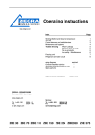
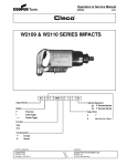
Operation & Service Manual
823106
2/01
116 & 136GL R.A. Series Extended
Right Angle Grinders
XXX G L
X
X
-
XXX
A
-
X X
X
Guard:
Series:
116, 136
3
4
Grinder:
Terminations:
Throttle:
L
Lever
Exhaust Terminations:
F
R
S
Front
Rear
Side
165
For additional product information visit our website at http://www.clecotools.com
NORTH AMERICA
CooperTools
P.O. Box 1410
Lexington, SC 29071
4
5
6
6M
1/4
5/16
3/8
6mm
C
Second
Third
150
3/16
3T
3/8-24
Wheel Type:
D
Type 27
W
Type 1 Wheel
Generation:
Concept
B
C
RPM:
135
3
3 In.
4 in.
Model:
A
Collet
Right Angle
EUROPE
Cooper Power Tools GmbH & Co.
Postfach 30
D-73461 Westhausen
1
Safety Recommendations
For your safety and the safety of others, read and understand the
safety recommendations before operating any grinder.
Installation of a filter-regulator-lubricator in the air supply line is
highly recommended.
Always wear protective equipment and clothing.
Before the tool is connected to air supply, check throttle for proper
operation, i.e., throttle moves freely and returns to closed position.
Being careful not to endanger adjacent personnel, clear air hose of
accumulated dust and moisture. Use protective barriers where
necessary — hot sparks can burn. Barriers also help reduce noise
levels. Before removing tool from service or changing accessories,
make sure air line is shut off and drained of air. This will prevent tool
from operating if throttle is accidently engaged. Do not use tool to
drain residual air from air line, instead use of a self-relieving valve
located near tool is highly recommended.
!
WARNING
Wear respirator where
necessary.
Grinding or other use of this tool may produce hazardous fumes
and/or dust. To avoid adverse health effects utilize adequate ventilation and/or a respirator. Respirators should be selected, fitted,
used and maintained in accordance with Occupational Safety and
Health Administration and other applicable regulations. Read the
material safety data sheet on any materials involved in the grinding
process.
Cleco grinders are designed to operate on 90 psig (6.2 bar) max.
air pressure. If the tool is properly sized and applied, higher air
pressure is unnecessary. Excessive air pressure increases the
loads and stresses on the tool parts and may result in breakage.
2
OVER
Repetitive work motions and/or vibration
can cause injury to hands and arms.
Use minimum hand grip force consistent with
proper control and safe operation.
Keep body and hands warm and dry.
Avoid anything that inhibits blood circulation.
Avoid continuous vibration exposure.
Keep wrists straight.
Avoid repeated bending of wrists and hands.
CAUTION
WARNING
!
WARNING
Hearing protection is recommended in high noise
areas (above 85 dBA). Close proximity of other
tools, reflective surfaces, process noises, and
resonant structures can substantially contribute
to the sound level experienced by the user.
!
!
Personal hearing protection is
recommended when operating
or working near this tool.
Impact resistant eye protection
must be worn while operating
or working near this tool.
CAUTION
202409
WARNING AND
INSTRUCTION LABEL
Read Operating Instructions carefully. Follow
the Safety Recommendations for your safety
and the safety of others.
3
• Do not wear loose fitting clothing, or clothing that may
restrict movement, become entangled or in any way
interfere with the safe operation of the grinder.
202101 & 869974
WARNING TAGS
2
• Gloves and other protective clothing should be worn as
required, unless they create a greater hazard.
203185
CAUTION LABEL
1
Hearing protection is recommended in high noise areas (above 85
dBA). Close proximity of additional tools, reflective surfaces, process noises, and resonant structures can substantially contribute to
the sound level experienced by the operator. Proper hearing conservation measures, including annual audiograms and training in the
use and fit of hearing protection devices may be necessary. For
additional information on hearing protection, refer to Federal OSHA
Regulations, 29 CFR, Section 1910.95, Occupational Noise Exposure, and American National Standards Institute, ANSI S12.6,
Hearing Protectors.
Do not remove this tag until
the operator of this tool has
read these safety precautions.
Personal hearing protection is
recommended when operating
or working near this tool.
0
CAUTION
MODEL
SERIAL NO.
!
The speed rating and warning information on the tool should be
maintained or replaced for legibility in the event of damage. Before
installing an accessory or a grinding wheel, after all tool repairs, and
whenever a grinder is issued for use, check the free speed of the
tool with a tachometer to make sure actual free speed at 90 psig
does not exceed rated free speed stamped on tool. Grinders in use
on the job must be checked at least once every 20 hours of operation,
or once a week, whichever is most frequent.
Guard (if wheel type grinder) must be securely attached to the
grinder with the bolt, nut and lockwasher in place and torqued to 3040 in. lbs.
TACHOMETER
Cleco
Caution: Faceshields do not provide unlimited protection against
flying particles and are not to be considered as eye protection. ANSI
Z87.1 states that separate eyewear shall be used. For additional
information on eye protection, refer to Federal OSHA Regulations,
29 CFR, Section 1910.133, Eye and Face Protection, and ANSI
Z87.1, Occupational and Educational Eye and Face Protection. This
standard is available from the American National Standards Institute, Inc., 11 West 42nd Street, New York, NY 10036.
6
Impact resistant eye protection
must be worn while operating
or working near this tool.
5
WARNING
4
!
!
WARNING
Fragments from an abrasive wheel
can cause serious injury or death.
Do not operate without proper
wheel guard in place.
INSPECT GRINDING WHEEL OR ACCESSORY
Fragments from a grinding wheel, mounted wheel or carbide burr
that breaks or comes apart while rotating can cause serious
injury or even death. Inspect grinding wheel or accessory. Check
the maximum safe RPM marked on wheel, accessory or package.
Never use wheels or accessories rated at or below actual tool
speed. Cracked, dropped, faulty, or bent accessories are dangerous. Suspect accessories should not be used and should be
disposed of. Look for cracks, chips, water stains, or signs of abuse
or improper storage. Causes of grinding wheel failures have been
traced to such factors as:
• Dropping, bumping, or abuse (careless handling of the
grinder)
• Improper mounting
• Imbalance
• Improper shipment or storage, or age
• Mismatched speed ratings
• Exposure to water, solvents, high humidity, freezing, and
extreme temperatures
Safety Recommendations
Wheels or accessories known to have been subjected to any of
the conditions above can burst violently and should be destroyed
rather than risk their use by someone who may not notice that
they are damaged.
Do not operate 116/136 RA grinder without a wheel guard if used
with Type 1 (straight) or Type 27 (depressed center) wheels.
Guard must not be modified, and any guard damaged or bent must
be replaced. Grinder must be used such that opening in guard is
away from operator.
CHECKFLANGE
A Type 1 wheel grinder's flanges must be relieved, free
of nicks that might cause stress concentrations on the
wheel which can cause cracks. Blotters must be used
1/3 Dia.
and be as large in diameter as the flanges. Diameters of of wheel
driving and outer flange must be equal and measure at
least 1/3 dia. of the wheel. If flanges are less than 1/3 dia.
of wheel, do not use grinder or select proper wheel. Relieved Flange
TYPE 1
Spindle end nut must be tightened firmly against outer
flange to insure necessary friction against blotters to
drive wheel. Caution: Overtightening can cause wheel breakage. Type
1 breakage can also occur if:
• Outer flange is left off
• Outer flange is reversed
• A washer is used in place of either flange
• Outer and driving flange are different diameters
• Blotters are not used
• Wheel is side loaded (Grind on periphery only!)
Check spindle
and
driving
! WARNING
GRINDING
flange
on
grindFACE
Extreme caution should
ers
used
with
be exercised not to use
Blotter
excessive side pressure.
Type 27 (deRelieved flanges
Excessive side pressure
pressed center)
minimum 1/3 dia.
can break the wheel and
of wheel dia.
w h e e l s .
result in severe injury.
Spindles must
TYPE 1
WHEEL
not be bent and
Guard not
shown for
threads must be
Do
not
grind
with
clarity.
free of any damside of Type 1 wheel.
age that might
keep a wheel from being centrally mounted or seated properly
against the driving flange. The spindle end nut should be tightened
to prevent wheel slippage and satisfactorly transfer the driving
torque of the spindle to the wheel through the adapter assembly.
COLLET EQUIPPED TOOLS
The collet should be checked to assure it is in good operating
condition and is secure to the tool. Accessories should be inserted
to full depth of the collet. Avoid excessive overhang and/or excessive down force that can result in vibration or a bent spindle.
Possible loss or ejection of accessory can result. Collet equipped
116/136 RA grinders are intended for use with small carbide burrs
and mounted wheels only. Do not use these tools for Type 1 or Type
27 wheel grinding. If your application calls for a Type 1 or Type 27
wheel, consult your Cleco representative for a wheel grinder equipped
with the proper wheel guard.
BEGINNING GRINDING OPERATION
Before using or after mounting a wheel or accessory, tool must be
run for one minute in a protected enclosure to check the integrity of
the wheel or accessory. During this time or any other time, no one
should stand in front or in line of the wheel or accessory. When
starting work with a cold wheel, apply it gradually to the workpiece
until it becomes warm. Do not continue to use a grinder if:
• It is not equipped with proper wheel guard
• It starts to vibrate
• You sense changes in tool speed or an unusual increase
in noise that would indicate tool is running at excessive
speed
• You notice excessive end play in spindle
• You hear any unusual sound from grinder
RETURN THE TOOL TO THE TOOL CRIB FOR SERVICE IMMEDIATELY!
Some individuals may be
susceptible to disorders
! WARNING
of the hands and arms
Repetitive work motions and/or vibration
may cause injury to hands and arms.
when performing tasks
Use minimum hand grip force consistent
consisting of highly rewith proper control and safe operation.
Keep body and hands warm and dry.
petitive motions and/or
Avoid anything that inhibits blood circulation.
exposure to extended viAvoid continuous vibration exposure.
Keep wrists straight.
bration.
Cumulative
Avoid repeated bending of wrists and hands.
trauma disorders such
as carpal tunnel syndrome and tendonitis may be caused or
aggravated by repetitious, forceful exertions of the hands and arms.
Vibration may contribute to a condition called Raynaud's Syndrome.
These disorders develop gradually over periods of weeks, months,
and years. It is presently unknown to what extent exposure to
vibrations or repetitive motions may contribute to the disorders.
Hereditary factors, vasculatory or circulatory problems, exposure to
cold and dampness, diet, smoking and work practices are thought
to contribute to the conditions.
Any tool operator should be aware of the following warning signs
and symptoms so that a problem can be addressed before it
becomes a debilitating injury. Any user suffering prolonged symptoms of tingling, numbness, blanching of fingers, clumsiness or
weakened grip, nocturnal pain in the hand, or any other disorder of
the shoulders, arms, wrists, or fingers is advised to consult a
physician. If it is determined that the symptoms are job related or
aggravated by movements and postures dictated by the job design,
it may be necessary for the employer to take steps to prevent further
occurrences. These steps might include, but are not limited to,
repositioning the workpiece or redesigning the workstation, reassigning workers to other jobs, rotating jobs, changing work pace,
and/or changing the type of tool used so as to minimize stress on
the operator. Some tasks may require more than one type of tool to
obtain the optimum operator/tool/task relationship.
The proper selection of the correct type of grinder is an important
ergo nomic consideration. Each application should be carefully
considered and the tool chosen that will minimize the stresses on
the operator that can lead to the onset of cumulative trauma
disorders. Some tasks require more than one type of tool to obtain
the optimum operator/tool/task relationship. Cleco has a complete
selection of tools including vertical, straight, angle, and extended
grinders that make possible the correct ergonomic match of the
operator, tool, and task.
The following suggestions will help reduce or moderate the effects
of repetitive work motions and/or extended vibration exposure:
3
Safety Recommendations
• Use a minimum hand grip force consistent with proper
control and safe operation
• Keep body and hands warm and dry (cold weather is
reported to be a major factor contributing to Raynaud's
Syndrome)
• Avoid anything that inhibits blood circulation
—Smoking Tobacco (another contributing factor)
—Cold Temperatures
—Certain Drugs
Avoid
Extension
OK
Neutral
Avoid
Flexion
Avoid
Radial Deviation
OK
Avoid
Neutral
Ulnar Deviation
• Tasks should be performed in such a manner that the
wrists are maintained in a neutral position, which is not
flexed, hyperextended, or turned side to side
• Stressful postures should be avoided — select a tool
appropriate for the job and work location
• Avoid highly repetitive movements of hands and wrists,
and continuous vibration exposure (after each period of
operation, exercise to increase blood circulation)
• Use quality accessories (the primary source of vibration
when using a grinder is an accessory that is out of
balance, out of round, untrue, or possibly any combination of all three; avoid excessive overhang of accessory
in collet)
• Use carbide burrs that are sharp, as dull burrs require
more force and effort to remove material
• Keep tool well maintained and replace worn parts (a
preventive maintanance program with scheduled inspections is highly recommended)
Work gloves with vibration reducing liners and wrist supports are
available from some manufacturers of industrial work gloves. Tool
wraps and grips are also available from a number of different
manufacturers. These gloves, wraps, and wrist supports are designed to reduce and moderate the effects of extended vibration
exposure and repetitive wrist trauma. Since they vary widely in
design, material, thickness, vibration reduction, and wrist support
qualities, it is recommended that the glove, tool wrap, or wrist
support manufacturer be consulted for items designed for your
specific application. WARNING! Proper fit of gloves is important.
Improperly fitted gloves may restrict blood flow to the fingers and
can substantially reduce grip strength.
USE QUALITY ABRASIVE WHEELS
The primary source of vibration when using a portable grinder is an
abrasive wheel that is out of balance, out of round, untrue, or
possibly any combination of all three.
The use of quality abrasive wheels which are well balanced, round,
and true is highly recommended as they have been found to
significantly reduce vibration. Some abrasive wheels lose their
balance, roundness, and trueness as they wear from use. Because
of the abusive nature of the vibration caused by out of balance, out
of round, and untrue condition of some abrasive wheels, it is felt that
these wheels are more suseptible to failure. Excessive vibration
may signal eminent wheel failure. Out of balance abrasive wheels
are dangerous. Flat spotting of the abrasive wheel, caused by
grinding the wheel to a stop after the power has been shut off can
4
result in changes to the balance and shape of the wheel. Be sure the
grinding wheel has stopped before setting the tool down. Set the tool in
a tool rest or tool holder when not in use.
WIRE BRUSHES
If a grinder is used for wire brushing applications the same
problems of balance, roundness, and truth as experienced with
abrasive wheels prevail. Use quality wire brushes.
USE A PREVENTIVE MAINTENANCE PROGRAM
Tool abuse or poor maintenance procedures can amplify and
contribute to the vibration produced by the abrasive wheel. A
preventive maintenance program featuring scheduled periodic
inspections and proper maintenance is the best way to assure
safety in your portable grinding operations. A well managed program can, for example, detect such things as speed variations due
to wear, flanges or spindles that have been damaged from abuse,
or bad bearings damaged by foreign matter or lack of lubrication.
Problems such as these can affect the wheel trueness when the
grinder is running and contribute to the vibration. Rotor blades that
are worn or chipped can lock up the motor and damage motor
components. Rotor blades should be checked periodically and
replaced if they measure less than 3/16" (4.7mm) at either end.
Replace if 3/16"
(4.7mm) or less
at either end.
Proper repair procedures and the use of original Cleco service parts
and bearings rather than substitutes will return the tool to factory
specifications of precision and balance, and minimize vibration.
PROPER LUBRICATION
An automatic in-line filter-regulator-lubricator is recommended as
it increases tool life and keeps the tool in sustained operation. The
in-line lubricator should be regularly checked and filled with a good
grade of 10W machine oil. Proper adjustment of in-line lubricator is
performed by placing a sheet of paper next to exhaust ports and
holding throttle open approximately 30 seconds. Lubricator is
properly set when a light stain of oil collects on paper. Excessive
amounts of oil should be avoided.
STORAGE
In the event it becomes necessary to store tool for an extended
period of time (overnight, weekend, etc.), it should receive a generous amount of lubrication at that time and run for several seconds
to distribute oil before disconnecting from air supply. This will
reduce corrosion and displace water that may be trapped in tool.
This information is a compilation of general safety practices obtained from various sources available at the date of production.
However, our company does not represent that every acceptable
safety practice is offered herein, or that abnormal or unusual
circumstances may not warrant or require additional procedures.
Your work may require additional specific safety procedures. Follow
these procedures as required by your company. For more information, see the latest edition of ANSI B186.1, Safety Code for Portable
Air Tools, and ANSI B7.1, Safety Requirements for the Use, Care,
and Protection of Abrasive Wheels, available from the American
National Standards Institute, Inc., 11 West 42nd Street, New York,
NY 10036.
116 & 136GLB & GLC
RIGHT ANGLE
GRINDER AND
SANDER EQUIPMENT
Type 1
Driving
Flange
Wheel Guard
Wheel Blotters
Both Sides
Relieved Flanges
1/3 Dia. of Wheel
Flange Dias. Equal
Clean, no nicks
or burrs
Spacer(s) 864159
Wheel Thickness No. Required
1/8"
2
3/16"
1
1/4"
None
Spindle
End Nut
TYPE 1 WHEEL with 3/8" Hole
Wheel Guard
Driving
Flange
Wheel
Blotter
Spindle
End Nut
TYPE 27 WHEEL with 3/8" Hole
Spindle
Adapter
4" Rubber
Pad
Pad Nut
CONTOUR SANDING PAD
TOOL
APPLICATION
SPINDLE
DRIVING
FLANGE
OUTER
FLANGE
NUT
WRENCH
GUARD
4" Type 27
with 3/8" Hole
3/8-24
202225
not applicable
843422
849834
849022
202227
3" Type 27
with 3/8" Hole
3/8-24
202225
not applicable
843422
849837
849022
202226
3" Type 1 with
3/8" Hole
3/8-24
202223
865991
203409
849837
849022
202226
4" Type 1 with
3/8" Hole
3/8-24
202223
865991
203409
849837
849022
202227
TOOL
APPLICATION
SPINDLE
ADAPTER
PAD
PAD NUT
WRENCH
4" Sanding Pad
3/8"-24 to 5/8"-11
869495
889271
849259
849834
5
OPERATING INSTRUCTIONS
READ SAFETY RECOMMENDATIONS
BEFORE CONNECTING TOOL.
OPERATION
The 116 and 136 RAB Series Right Angle Grinders are designed
to operate on 90 psig (6.2 bar) maximum air pressure, using a 1/
4" hose up to 8' in length for the 116 and a 5/16" hose for the 136.
If additional length is required, the next larger hose size may be
connected to the 8' whip hose.
LUBRICATION
An automatic in-line filter-lubricator is recommended as it increases tool life and keeps the tool in sustained operation. The inline lubricator should be regularly checked and filled with a good
grade of 10W machine oil. Proper adjustment of the in-line
lubricator is performed by placing a sheet of paper next to the
exhaust ports and holding the throttle open approximately 30
seconds. The lubricator is properly set when a light stain of oil
collects on the paper. Excessive amounts of oil should be avoided.
Application of the tool should govern how frequently it is greased.
It is recommended that the right angle gears receive a generous
amount of NLGI 2-EP grease through the grease fittings after 40
hours of operation.
STORAGE
In the event that it becomes necessary to store the tool for an
extended period of time (overnight, weekend, etc.), it should
receive a generous amount of lubrication at that time and again
when returned to service. The tool should be stored in a clean and
dry environment.
allows the pinion gear to engage the driven gear. Screw a 3/8-24
nut on the spindle and hold with a box end wrench. Put a spacer
over the spindle needle bearing and clamp the housing in a vise.
Now proceed to loosen the spline adapter with a 14mm six (6)
point deep socket.
The pinion bearing retainer, No. 863564, may be removed by
utilizing a 5/8" hex nut and a 5/8" deep socket. Drop the hex nut
over the pinion shaft and engage the hex in the bearing retainer
and unscrew the retainer using the deep socket. Unscrew the
plug, No. 842366, and using a suitable driver, drive the pinion, No.
202624, and related bearings out of the angle head.
REASSEMBLY
The tool is reassembled in the reverse order of disassembly.
Wash all parts in a solvent and inspect for damage or wear. Rotor
blades should be replaced at every repair cycle or if they measure
less than 3/16" (4.7mm) at either end. Replace bearings that are
rough or have excessive end play.
IMPORTANT: When replacing pinion gear 202624 or driven
gear 202201, both gears should be replaced for best results.
When reassembling the spindle, No. 202194, bearing, No. 202197,
driven gear, No. 202201 and spindle lock nut, No. 202199, use
Locktite #271 on the spindle lock nut No. 202199. Also use #271
Locktite on the Spindle Bearing Cap No. 202196.
Slip pinion needle bearing, No. 869864, (unstamped end first) on
the pinion, No. 202624, and press (press on the bearing's stamped
end) the bearing in to a depth of 7/8" from the face of the bearing
bore. Install pinion ball bearing, No. 202333, (shield to the rear) and
bearing retainer, No. 863564, in the head and tighten retainer
securely using the 5/8" hex nut and 5/8" deep socket. Using a
suitable driver through the hole in the top of the head, drive the
pinion back to make sure it is seated properly in the head.
Important: When installing front rotor bearing. No. 202332, the
shielded side should be assembled toward the rear of the tool.
SERVICE INSTRUCTIONS
DISASSEMBLY
To disassemble the tool, unscrew the right angle head (left hand
threads). This will allow the removal of the motor unit from the
backhead.
To remove the splined nut, 202236, use a 14mm six (6) point box
wrench and a 3/16" hex wrench. Insert the hex wrench into the
rotor shaft and unscrew the nut. Use a suitable driver to drive the
front rotor shaft out of the front rotor bearing. After removing the
cylinder and rotor blades, the rear rotor shaft may be driven out of
the rear rotor bearing.
To disassemble the right angle head, unscrew the spindle bearing
cap. This will permit the removal of the spindle assembly.
Use a 14mm six (6) point deep socket to remove the spline
adapter, No.202625. If the pinion is not engaging the driven gear
because of wear, remove the bearing, 202197, from the spindle
and put the driven gear back on the spindle. Insert the spindle and
driven gear back into the housing. With a brass hammer drive the
spindle needle bearing, No. 202198, out of the housing until it
6
Install the front rotor bearing in the front bearing plate and measure
the distance from the face of the bearing plate to the inner race of
the bearing with the bearing race loaded rearward. Select or fit by
sanding a rotor collar .001" (.025mm) to .002" (.050mm) longer
than this measurement. Install the rotor blades, cylinder, rear
bearing plate and rear bearing on the rotor. After final assembly of
the motor unit, the cylinder should be held securely but not tightly
between the two (2) plates. The rotor should not rub either plate.
When installing the splined nut, No. 202236, on the rotor, the
undercut end should be toward the bearing.
When installing a motor into a rear exhaust backhead, the steel
ball located in the front plate must line up with the groove in the
backhead. Tighten all joints securely during reassembly. Head
positioning spacers are used to position the right angle head in
relationship to the throttle lever. Each .005" added or subtracted
will change the location of the head approximately 30 degrees.
Place a few drops of 10W machine oil in the air inlet to ensure
positive lubrication of all motor parts as soon as air is applied.
CAUTION: After the grinder is reassembled, be sure to check the
free speed (R.P.M.) for proper speed with a dependable tachometer before returning the grinder to service.
116 & 136 EXTENDED RIGHT ANGLE HEAD
867926
Side Exhaust Only
Head Positioning
Spacers
863926
.005"
869559
.010"
869560
.020"
Side Exhaust Deflector
Type Tool
Part No.
Type 1 & 27 202203
Collet
202204
869475
202333
869864
863564
202235
202625
847234
202236
842366
202198
202193
202624
Muffler
Model Part No.
116
202338
136
869452
202223
202196
865991
203409
TYPE 1 WHEEL
1/4" Maximum Wheel Thickness
Front Exhaust Deflector
Type Tool
Part No.
Type 1 & 27 202207
Collet
202208
3/8-24 Spindle
202194
202199
202201
202197
TYPE 27 WHEEL
849022
202225
1/4" Maximum Wheel Thickness
843422
3/8-24 Stub Spindle
849837
9/16"
202195-4
847803
11/16"
202860
5/8"
Integral Collet (200 series)
3/4"
849844
202859
Wheel Guard
Size Part No.
3"
202226
4"
202227
PART NO.
202193
202194
202195
202196
202197
202198
202199
202201
202203*
202204*
202207*
202208*
202223*
202225*
202226*
202227*
202235*
202236*
202333
202338*
202624
202625
202859
202860
NAME OF PART
Angle Head
3/8-24 Spindle
3/8-24 Stub Spindle
Spindle Bearing Cap
Spindle Ball Bearing
Spindle Needle Bearing
Spindle Lock Nut
Driven Gear
Side Exhaust Deflector
Side Exhaust Deflector
Front Exhaust Deflector
Front Exhaust Deflector
Type 1 Driving Flange
Type 27 Driving Flange
3" Wheel Guard
4" Wheel Guard
Spline Coupling
Splined Nut
Pinion Ball Bearing
Muffler
Pinion
Spline Adapter
Collet Spindle
Spindle Bearing Cap
849834
Collet
Size
Part No.
3/16" 865423
6mm 864158
1/4"
847811
5/16" 865501
3/8"
847805
QTY.
PART NO.
1
1
1
1
1
1
1
1
1
1
1
1
1
1
1
1
1
1
1
1
1
1
1
1
203409
842366
843422*
847234*
847803
847805
847811
849022*
849834*
849837*
849844*
863564*
863926*
864158
864159*
865423
865501
865991*
867926*
869452*
869475*
869559*
869560*
869864
NAME OF PART
Spindle End Nut - Type 1
Plug
Spindle End Nut - Type 27
"O"-Ring 1-1/8" x 1-1/4"
Collet Lock Nut
3/8" Collet (Opt.)
1/4" Collet (Std.)
Spindle Hex Wrench
Spanner Wrench
9/16" x 11/16" Wrench
5/8" x 3/4" Wrench
Bearing Retainer
.005" Spacer
6mm Collet (Opt.)
Driving flange Spacer (if required)
3/16" Collet (Opt.)
5/16" Collet (Opt.)
Type 1 Outer Flange
"O"-Ring 1-3/16" x 1-5/16"
Muffler
Retainer Ring
.010" Spacer
.020" Spacer
Pinion Needle Bearing
QTY.
1
1
1
1
1
1
1
1
1
2
1
1
**
1
**
1
1
1
1
1
1
**
**
1
* Denotes parts not included in subassemblies.
** Number of spacers required is variable.
The complete angle head can be purchased as a subassembly using the following part numbers.
3/8-24 Spindle - Part No. 201145
3/8-24 Stub Spindle - Part No. 201144
Integral collet - Part No. 201240
7
116 & 136 EXTENDED RIGHT ANGLE MOTOR
Front Bearing Plate
Type Exhaust
Part No.
Front/Side 202335
Rear
202334
Rotor
Model Part No.
116 869780
136 869781
Rotor Blade
Model Part No.
116 867816
136 869449
202332
869445
812165
Cylinder
Model Part No.
116 869450
136 869451
OPTIONAL ROTOR COLLAR
PART NO.
SIZE
864487
864488
864489
864490
847525
864492
864493
865416
865417
202076
202187
202188
.120
.121
.122
.123
.124
.125
.126
.127
.128
.129
.130
.131
Part No.
Name of Part
202285
202332
202334
202335
812165
847525
864489
864493
865417
Rear Bearing Plate
Front Rotor Bearing
Front Bearing Plate
Front Bearing Plate
Cylinder Pin
Rotor Collar .124"
Rotor Collar .122"
Rotor Collar .126"
Rotor Collar .128"
* Only one rotor collar required.
8
812165
Qty.
Part No.
1
1
1
1
2
*
*
*
*
867816
869445
869449
869450
869451
869638
869780
869781
Rear Bearing Plate
Type Exhaust
Part No.
Front/Side
869638
Rear
202285
Name of Part
Rotor Blade
Rear Rotor Bearing
Rotor Blade
Cylinder (includes one (1) pin)
Cylinder (includes one (1) pin) Rear
Bearing Plate
Rotor
Rotor
Qty.
4
1
4
1
1
1
1
1
116 & 136 EXTENDED RIGHT ANGLE HANDLES
Front/Side Exhaust
Backhead
Model No.
Part No.
116G-135A
202329
116G-165A
202107
136G-135A
202331
136G-165A
202110
136G-150A
203966
ALL MODELS
202106
202105
869855
845409
847808
202104
869712
202103
203043
846664
Rear Exhaust
Extended Backhead
165A-C 204145
135A-W 204205
135A-D 204205
165A-W 204144
165A-D 204144
869489
FRONT/SIDE EXHAUST MODELS
863880
869845
202288
844309
REAR EXHAUST MODEL
Rear Exhaust
135
202216
165A-C
202221
165A-W 202217
165A-D 202217
Part No.
202103
202104
202105
202106
202107
202110
202216
202221
202287
202288
202329
202331
203043
203966
833188
Name of Part
Inlet Bushing
Throttle Valve Pin (incl. 869712)
Toggle
Lock-off Lever
Backhead (incl. 846664)
Backhead (incl. 846664)
Backhead (incl. 846664)
Backhead (incl. 846664)
Inlet Bushing (833300)
Throttle Valve
Backhead (incl. 846664)
Backhead (incl. 846664)
Inlet Screen
Backhead (incl. 846664)
Throttle Valve Spring
MODELNO.
116GLB-135A
116GLB-165A
136GLFB-150A
847767
847272
869850
869844
202287
863454
833188
Qty.
Part No.
1
1
1
1
1
1
1
1
1
1
1
1
1
1
1
833300
844309
845409
846664
847272
847767
847808
863454
863880
869489
869712
869844
869845
869850
869855
COMPLETE HANDLE SUBASSEMBLIES
PART NO.
MODEL NO.
201017
136GLB-135A
861991
136GLRB-135A
201571
136GLRC-165A-C
136GLB-165A
136GLRB-165A-W
136GLRB-165A-D
136GLRE165A-W
136GLRE-165A-D
136GLRE-135A-W
136GLRE-135A-D
136GLRE-165A-C
833300
Name of Part
Inlet Screen
"O"-Ring 7/16" X 5/8"
Toggle Pin
Throttle Pin Bushing
"O"-Ring 5/8" X 3/4"
Throttle Valve Spring
Throttle Lever Pin
"O"-Ring 9/16" X 11/16"
"O"-Ring 1-1/4" X 1-3/8"
Throttle Valve
"O"-Ring 5/64" X 13/64"
Exhaust Deflector
Throttle Valve Seat
Muffler Felt
Toggle Spring
PART NO.
201018
861138
861131
861995
861135
861135
201651
201651
201626
201626
201627
Qty.
1
1
1
1
1
1
1
1
1
1
1
1
1
2
1
The lock-off lever can be
purchased as a subassembly
using part no. 861992.
9
NOTES
10
NOTES
11
CooperTools
670 Industrial Drive
Lexington, SC 29072
Phone: (803) 359-1200
Fax: (803) 359-2013
www.clecotools.com
12