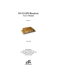
1
Lassen-SK8™
Embedded GPS Module
System Designer Reference Manual
Part Number: 34149-01
Firmware: 7.20-7.52
Date: August 1997
Trimble Navigation Limited
Commercial Systems Group
645 North Mary Avenue
Post Office Box 3642
Sunnyvale, CA 94088-3642
U.S.A.
+1-800-827-8000 in North America
+1-408-481-8000 International
FAX: +1-408-730-2082
U.S. Technical Assistance and Repair
+1-800--SOS-4-TAC in North America
+1-408-481-6940 International
FAX: +1-408-481-6020
European Technical Assistance and Repair
+44-1256-1622-858-421
Copyrights
© 1997 Trimble Navigation Limited. All rights reserved. No part of this manual may be copied, photocopied,
reproduced, translated, or reduced to any electronic medium or machine-readable form without prior written consent
from Trimble Navigation Limited.
Printed in the United States of America. Printed on recycled paper.
Revision Notice
This is the first release of the Lassen-SK8™ Embedded GPS Module System Designer Reference Manual, Part
Number 34149-01, August 1997.
This manual supersedes the Lassen-SK8™ GPS Board for Embedded Applications, System Designer Reference
Manual, Part Number 29473-00, Revision B, June 1997, © 1996 Trimble Navigation Limited.
Trademarks
SVeeSix, SVeeSix-CM3, LASSEN-SK8, Acutis, Acutime, AcutimeII, and TSIP are trademarks of Trimble
Navigation Limited. IBM is a registered trademark of International Business Machines, Inc. MS-DOS and Windows
is a trademark of Microsoft Corporation. Intel is a trademark of Intel Corporation. All other brand names are
trademarks of their respective holders.
Disclaimer of Warranty
EXCEPT AS INDICATED IN “LIMITED WARRANTY” HEREIN, TRIMBLE HARDWARE, SOFTWARE, FIRMWARE
AND DOCUMENTATION IS PROVIDED “AS IS” AND WITHOUT EXPRESS OR LIMITED WARRANTY OF ANY KIND
BY EITHER TRIMBLE OR ANYONE WHO HAS BEEN INVOLVED IN ITS CREATION, PRODUCTION, OR
DISTRIBUTION INCLUDING BUT NOT LIMITED TO THE IMPLIED WARRANTIES OF MERCHANTABILITY AND
FITNESS FOR A PARTICULAR PURPOSE. THE ENTIRE RISK, AS TO THE QUALITY AND PERFORMANCE OF THE
TRIMBLE HARDWARE, SOFTWARE, FIRMWARE AND DOCUMENTATION, IS WITH YOU. SOME STATES DO NOT
ALLOW THE EXCLUSION OF IMPLIED WARRANTIES, SO THE ABOVE EXCLUSION MAY NOT APPLY TO YOU.
Limitation of Liability
IN NO EVENT WILL TRIMBLE OR ANY PERSON INVOLVED IN THE CREATION, PRODUCTION, OR DISTRIBUTION
OF THE TRIMBLE PRODUCT BE LIABLE TO YOU ON ACCOUNT OF ANY CLAIM FOR ANY DAMAGES, INCLUDING
ANY LOST PROFITS, LOST SAVINGS, OR OTHER SPECIAL, INCIDENTAL, CONSEQUENTIAL, OR EXEMPLARY
DAMAGES, INCLUDING BUT NOT LIMITED TO ANY DAMAGES ASSESSED AGAINST OR PAID BY YOU TO ANY
THIRD PARTY, RISING OUT OF THE USE, LIABILITY TO USE, QUALITY OR PERFORMANCE OF SUCH TRIMBLE
PRODUCT INCLUDING HARDWARE, SOFTWARE, FIRMWARE, AND DOCUMENTATION, EVEN IF TRIMBLE OR
ANY SUCH PERSON OR ENTITY HAS BEEN ADVISED OF THE POSSIBILITY OF DAMAGES, OR FOR ANY CLAIM
BY ANY OTHER PARTY. SOME STATES DO NOT ALLOW THE LIMITATION OR EXCLUSION OF LIABILITY FOR
INCIDENTAL OR CONSEQUENTIAL DAMAGES SO, THE ABOVE LIMITATIONS MAY NOT APPLY TO YOU.
Software and Firmware Limited Warranty
Trimble warrants that Software and Firmware products will substantially conform to the published specifications
provided it is used with the Trimble products, computer products, and operating system for which it was designed.
For a period of ninety (90) days, commencing thirty (30) days after shipment from Trimble, Trimble also warrants
that the magnetic media on which Software and Firmware are distributed and the documentation are free from defects
in materials and workmanship. During the ninety (90) day warranty period, Trimble will replace defective media or
documentation, or correct substantial program errors at no charge. If Trimble is unable to replace defective media or
documentation, or correct program errors, Trimble will refund the price paid for The Software. These are your sole
remedies for any breach in warranty.
Hardware Limited Warranty
Trimble Navigation Limited products are warranted against defects in material and workmanship for a period of one
year. The warranty period shall commence thirty (30) days after shipment from Trimble’s factory. Warranty service
will be provided at a designated Trimble Service Center. Trimble will at its option either repair or replace products
that prove to be defective. The Customer shall pay all shipping charges for products returned to Trimble for warranty
service. Trimble shall pay all shipping charges for the return of products to the Customer.
This warranty shall not apply to defects resulting from one or more of the following:
•
Improper or inadequate maintenance by the buyer
•
Buyer-supplied software or interfacing
•
Unauthorized modification or misuse
•
Operation outside of the environmental specifications of the product
•
Improper installation, where applicable
•
Lightning or other electrical discharge
•
Fresh or salt water immersion or spray
•
Normal wear and tear on consumable parts (for example, batteries)
No other warranty is expressed or implied. Trimble Navigation Limited specifically disclaims the implied warranties
of fitness for a particular purpose and merchantability.
Table of Contents
Preface
Scope and Audience . . . . . . . . .
Lassen-SK8 Manual Organization . .
Technical Assistance . . . . . . . . .
Email. . . . . . . . . . . .
Worldwide Web . . . . . .
Internet FTP Address . . .
FaxBack . . . . . . . . . .
Reader Comment Form. . . . . . . .
Document Conventions. . . . . . . .
Notes, Tips, Cautions, and Warnings.
1
.
.
.
.
.
.
.
.
.
.
.
.
.
.
.
.
.
.
.
.
.
.
.
.
.
.
.
.
.
.
.
.
.
.
.
.
.
.
.
.
.
.
.
.
.
.
.
.
.
.
.
.
.
.
.
.
.
.
.
.
.
.
.
.
.
.
.
.
.
.
.
.
.
.
.
.
.
.
.
.
.
.
.
.
.
.
.
.
.
.
.
.
.
.
.
.
.
.
.
.
.
.
.
.
.
.
.
.
.
.
.
.
.
.
.
.
.
.
.
.
.
.
.
.
.
.
.
.
.
.
.
.
.
.
.
.
.
.
.
.
.
.
.
.
.
.
.
.
.
.
.
.
.
.
.
.
.
.
.
.
.
.
.
.
.
.
.
.
.
.
.
.
.
.
.
.
.
.
.
.
.
.
.
.
.
.
.
.
.
.
.
.
.
.
.
.
.
.
.
.
.
.
.
.
.
.
.
.
.
.
.
.
.
.
.
.
.
.
.
.
.
.
.
.
.
.
.
.
.
.
.
.
.
.
.
.
.
.
.
.
.
.
.
.
.
.
.
.
.
.
xix
xx
xx
xx
xxi
xxi
xxi
xxi
xxii
xxii
.
.
.
.
.
.
.
.
.
.
.
.
.
.
.
.
.
.
.
.
.
.
.
.
.
.
.
.
.
.
.
.
.
.
.
.
.
.
.
.
.
.
.
.
.
.
.
.
.
.
.
.
.
.
.
.
.
.
.
.
.
.
.
.
.
.
.
.
.
.
.
.
.
.
.
.
.
.
.
.
.
.
.
.
.
.
.
.
.
.
.
.
.
.
.
.
.
.
.
.
.
.
.
.
.
.
.
.
.
.
.
.
.
.
.
.
.
.
.
.
.
.
.
.
.
.
.
.
.
.
.
.
.
.
.
.
.
.
.
.
.
.
.
.
.
.
.
.
.
.
.
.
.
.
.
.
.
.
.
.
.
.
.
.
.
.
.
.
.
.
.
.
.
.
.
.
.
.
.
.
.
.
.
.
.
.
.
.
.
.
.
.
.
.
.
.
.
.
.
.
.
.
.
.
.
.
.
.
.
.
.
.
.
.
.
.
.
.
.
.
.
.
.
.
.
.
.
.
.
.
.
.
.
.
.
.
.
.
.
.
.
.
.
.
.
.
.
.
.
.
.
.
.
.
.
.
.
.
.
.
1-2
1-3
1-3
1-3
1-3
1-5
1-8
1-9
1-10
1-11
.
.
.
.
.
.
.
.
.
.
.
.
.
.
.
.
.
.
.
.
.
.
.
.
.
.
.
.
.
.
.
.
.
.
.
.
.
.
.
.
.
.
.
.
.
.
.
.
.
.
.
.
.
.
.
.
.
.
.
.
.
.
.
.
.
.
.
.
.
.
.
.
.
.
.
.
.
.
.
.
.
.
.
.
.
.
.
.
.
.
.
.
.
.
.
.
.
.
.
.
.
.
.
.
.
.
.
.
.
.
.
.
.
.
.
.
.
.
.
.
.
.
.
.
.
.
.
.
.
.
.
.
.
.
.
.
.
.
.
.
.
.
.
.
.
.
.
.
.
.
.
.
.
.
.
.
.
.
.
.
.
.
.
.
.
.
.
.
.
.
.
.
.
.
.
.
.
.
.
.
.
.
2-1
2-3
2-3
2-4
2-5
2-5
2-5
Starter Kit
1.1
1.2
1.3
1.4
1.5
1.6
2
.
.
.
.
.
.
.
.
.
.
Lassen-SK8 Overview . . . . . . . .
1.1.1
Interface Protocols . . . . .
Port 1 . . . . . . . . . . .
Port 2 . . . . . . . . . . .
1.1.2
Starter Kit Components . .
GPS Receiver Module . . . . . . . .
Antenna . . . . . . . . . . . . . . . .
Power . . . . . . . . . . . . . . . . .
Hardware Setup. . . . . . . . . . . .
Running the TSIP Interface Program.
Hardware Integration
2.1
2.2
2.3
2.4
2.5
2.6
2.7
The Lassen-SK8 Receiver Module .
Interface Connector. . . . . . . . .
Power Requirement. . . . . . . . .
Serial Interface . . . . . . . . . . .
Pulse Per Second . . . . . . . . . .
Mounting . . . . . . . . . . . . . .
RF Shield . . . . . . . . . . . . . .
Lassen-SK8 Embedded GPS Module
.
.
.
.
.
.
.
v
3
Software Interface
3.1
3.2
3.3
3.4
3.5
3.6
4
3-1
3-1
3-2
3-3
3-3
3-4
3-5
3-6
3-6
3-7
3-7
3-8
3-8
Operation and Performance
4.1
4.2
4.3
4.4
4.5
4.6
vi
Start-up . . . . . . . . . . . . . . . . . . . . . . . . . . . . . . . . . . . . . . . . . .
Software Tool Kits . . . . . . . . . . . . . . . . . . . . . . . . . . . . . . . . . . . .
Communicating with the Lassen-SK8 Module. . . . . . . . . . . . . . . . . . . . . .
Protocol Summary . . . . . . . . . . . . . . . . . . . . . . . . . . . . . . . . . . . .
3.4.1
TSIP Data Output . . . . . . . . . . . . . . . . . . . . . . . . . . . . . . .
Configuring the SK 8 receiver output protocol from TSIP to TAIP protocol.
3.4.2
TAIP Data Output . . . . . . . . . . . . . . . . . . . . . . . . . . . . . . .
Configuring the SK 8 receiver output protocol from TAIP to TSIP protocol
TAIP message PR . . . . . . . . . . . . . . . . . . . . . . . . . . . . . . .
3.4.3
NMEA 0183 Data Output . . . . . . . . . . . . . . . . . . . . . . . . . . .
Timing Applications . . . . . . . . . . . . . . . . . . . . . . . . . . . . . . . . . . .
3.5.1
Effect of GPS Week Number Roll-over (WNRO) . . . . . . . . . . . . . .
Lassen/Palisade Family Firmware Version 7.xx Software Modifications . .
Differential GPS . . . . . . . . . . . . . . . . . . . . . . . . . . . . . . . . . . . . .
GPS Satellite Message . . . . . . . . . . .
Satellite Acquisition and Time to First Fix.
4.2.1
Cold-Start . . . . . . . . . . . .
4.2.2
Warm Start. . . . . . . . . . . .
4.2.3
Garage Search Strategy . . . . .
4.2.4
Hot Start . . . . . . . . . . . . .
Satellite Mask Settings . . . . . . . . . . .
4.3.1
Elevation Mask . . . . . . . . .
4.3.2
SNR Mask . . . . . . . . . . . .
4.3.3
PDOP Mask . . . . . . . . . . .
4.3.4
PDOP Switch . . . . . . . . . .
Standard Operating Modes . . . . . . . . .
4.4.1
Fix Modes . . . . . . . . . . . .
2D Manual . . . . . . . . . . . .
3D Manual . . . . . . . . . . . .
2D/3D Automatic . . . . . . . .
Differential GPS Operating Modes. . . . .
4.5.1
DGPS On . . . . . . . . . . . .
4.5.2
DGPS Off . . . . . . . . . . . .
4.5.3
DGPS Automatic . . . . . . . .
4.5.4
Differential GPS Operation . . .
Position Accuracy . . . . . . . . . . . . .
.
.
.
.
.
.
.
.
.
.
.
.
.
.
.
.
.
.
.
.
.
.
.
.
.
.
.
.
.
.
.
.
.
.
.
.
.
.
.
.
.
.
.
.
.
.
.
.
.
.
.
.
.
.
.
.
.
.
.
.
.
.
.
.
.
.
.
.
.
.
.
.
.
.
.
.
.
.
.
.
.
.
.
.
.
.
.
.
.
.
.
.
.
.
.
.
.
.
.
.
.
.
.
.
.
.
.
.
.
.
.
.
.
.
.
.
.
.
.
.
.
.
.
.
.
.
.
.
.
.
.
.
.
.
.
.
.
.
.
.
.
.
.
.
.
.
.
.
.
.
.
.
.
.
.
.
.
.
.
.
.
.
.
.
.
.
.
.
.
.
.
.
.
.
.
.
.
.
.
.
.
.
.
.
.
.
.
.
.
.
.
.
.
.
.
.
.
.
.
.
.
.
.
.
.
.
.
.
.
.
.
.
.
.
.
.
.
.
.
.
.
.
.
.
.
.
.
.
.
.
.
.
.
.
.
.
.
.
.
.
.
.
.
.
.
.
.
.
.
.
.
.
.
.
.
.
.
.
.
.
.
.
.
.
.
.
.
.
.
.
.
.
.
.
.
.
.
.
.
.
.
.
.
.
.
.
.
.
.
.
.
.
.
.
.
.
.
.
.
.
.
.
.
.
.
.
.
.
.
.
.
.
.
.
.
.
.
.
.
.
.
.
.
.
.
.
.
.
.
.
.
.
.
.
.
.
.
.
.
.
.
.
.
.
.
.
.
.
.
.
.
.
.
.
.
.
.
.
.
.
.
.
.
.
.
.
.
.
.
.
.
.
.
.
.
.
.
.
.
.
.
.
.
.
.
.
.
.
.
.
.
.
.
.
.
.
.
.
.
.
.
.
.
.
.
.
.
.
.
.
.
.
.
.
.
.
.
.
.
.
.
.
.
.
.
.
.
.
.
.
.
.
.
.
.
.
.
.
.
.
.
.
.
.
.
.
.
.
.
.
.
.
.
.
.
.
.
.
.
.
.
.
.
.
.
.
.
.
.
.
.
.
.
.
.
.
.
.
.
.
.
.
.
.
.
.
.
.
.
.
.
.
.
.
.
.
.
.
.
.
.
.
.
.
.
.
4-1
4-2
4-2
4-2
4-3
4-3
4-3
4-4
4-4
4-4
4-5
4-5
4-5
4-5
4-6
4-6
4-6
4-6
4-6
4-6
4-7
4-7
Lassen-SK8 Embedded GPS Module
4.6.1
Selective Availability (SA)
4.6.2
Differential GPS (DGPS) .
4.7 Coordinate Systems. . . . . . . . . .
4.7.1
TSIP Coordinate Systems .
4.7.2
NMEA 0183 . . . . . . . .
4.7.3
TAIP . . . . . . . . . . . .
4.8 Performance Characteristics . . . . .
4.8.1
Update Rate . . . . . . . .
4.8.2
Dynamic Limits . . . . . .
4.8.3
Re-Acquisition. . . . . . .
4.9 GPS Timing. . . . . . . . . . . . . .
4.9.1
Serial Time Output . . . .
4.9.2
Timing Pulse Output (PPS)
4.10 System Architecture . . . . . . . . .
A
.
.
.
.
.
.
.
.
.
.
.
.
.
.
.
.
.
.
.
.
.
.
.
.
.
.
.
.
.
.
.
.
.
.
.
.
.
.
.
.
.
.
.
.
.
.
.
.
.
.
.
.
.
.
.
.
.
.
.
.
.
.
.
.
.
.
.
.
.
.
.
.
.
.
.
.
.
.
.
.
.
.
.
.
.
.
.
.
.
.
.
.
.
.
.
.
.
.
.
.
.
.
.
.
.
.
.
.
.
.
.
.
.
.
.
.
.
.
.
.
.
.
.
.
.
.
.
.
.
.
.
.
.
.
.
.
.
.
.
.
.
.
.
.
.
.
.
.
.
.
.
.
.
.
.
.
.
.
.
.
.
.
.
.
.
.
.
.
.
.
.
.
.
.
.
.
.
.
.
.
.
.
.
.
.
.
.
.
.
.
.
.
.
.
.
.
.
.
.
.
.
.
.
.
.
.
.
.
.
.
.
.
.
.
.
.
.
.
.
.
.
.
.
.
.
.
.
.
.
.
.
.
.
.
.
.
.
.
.
.
.
.
.
.
.
.
.
.
.
.
.
.
.
.
.
.
.
.
.
.
.
.
.
.
.
.
.
.
.
.
.
.
.
.
.
.
.
.
.
.
.
.
.
.
.
.
.
.
.
.
.
.
.
.
.
.
.
.
.
.
.
.
.
.
.
.
.
.
.
.
.
.
.
.
.
.
.
.
.
.
.
.
.
.
.
.
.
.
.
.
.
.
.
.
.
.
.
.
.
.
.
.
.
.
.
.
.
.
.
.
.
.
.
.
.
.
.
.
.
.
.
.
.
.
4-7
4-7
4-8
4-8
4-9
4-9
4-9
4-9
4-9
4-9
4-10
4-10
4-11
4-11
Interface Scope . . . . . . . . . . . . . . . . . . . . . . . . . . . . . . . . . . .
Automatic Output Packets . . . . . . . . . . . . . . . . . . . . . . . . . . . . .
Customizing Receiver Operations . . . . . . . . . . . . . . . . . . . . . . . . .
A.3.1
TAIP Customizing . . . . . . . . . . . . . . . . . . . . . . . . . . . .
A.3.2
NMEA Customizing . . . . . . . . . . . . . . . . . . . . . . . . . . .
A.3.3
Reconfiguring to Factory Default Settings . . . . . . . . . . . . . . .
Automatic Position and Velocity Reports . . . . . . . . . . . . . . . . . . . . .
Warm Start Packets . . . . . . . . . . . . . . . . . . . . . . . . . . . . . . . . .
Packets Output at Power-Up . . . . . . . . . . . . . . . . . . . . . . . . . . . .
Differential GPS Packets . . . . . . . . . . . . . . . . . . . . . . . . . . . . . .
Timing Packets . . . . . . . . . . . . . . . . . . . . . . . . . . . . . . . . . . .
Satellite Data Packets. . . . . . . . . . . . . . . . . . . . . . . . . . . . . . . .
Background Packets . . . . . . . . . . . . . . . . . . . . . . . . . . . . . . . .
Backwards Incompatibility of Lassen-SK8 Packets with Previous TSIP Versions
Recommended TSIP Packets . . . . . . . . . . . . . . . . . . . . . . . . . . . .
Command Packets Sent to the Receiver . . . . . . . . . . . . . . . . . . . . . .
Report Packets Sent by the GPS Receiver to the User . . . . . . . . . . . . . . .
Key Setup Parameters or Packet BB . . . . . . . . . . . . . . . . . . . . . . . .
A.15.1 Packet 0xBB - Set Fix Mode . . . . . . . . . . . . . . . . . . . . . .
A.15.2 Dynamics Code . . . . . . . . . . . . . . . . . . . . . . . . . . . . .
A.15.3 Elevation Mask . . . . . . . . . . . . . . . . . . . . . . . . . . . . .
A.15.4 Signal Level Mask . . . . . . . . . . . . . . . . . . . . . . . . . . . .
A.15.5 DOP Mask and Switch . . . . . . . . . . . . . . . . . . . . . . . . .
.
.
.
.
.
.
.
.
.
.
.
.
.
.
.
.
.
.
.
.
.
.
.
.
.
.
.
.
.
.
.
.
.
.
.
.
.
.
.
.
.
.
.
.
.
.
.
.
.
.
.
.
.
.
.
.
.
.
.
.
.
.
.
.
.
.
.
.
.
A-1
A-2
A-3
A-3
A-3
A-3
A-5
A-6
A-7
A-7
A-8
A-8
A-8
A-9
A-11
A-13
A-15
A-16
A-17
A-17
A-17
A-18
A-18
Trimble Standard Interface Protocol
A.1
A.2
A.3
A.4
A.5
A.6
A.7
A.8
A.9
A.10
A.11
A.12
A.13
A.14
A.15
Lassen-SK8 Embedded GPS Module
vii
A.15.6 Packet 0xBB - Set DGPS Mode .
A.16 Packet Structure . . . . . . . . . . . . . .
A.17 Packet Descriptions. . . . . . . . . . . . .
A.17.1 Command Packet 0x1D . . . . .
A.17.2 Command Packet 0x1E . . . . .
A.17.3 Command Packet 0x1F . . . . .
A.17.4 Command Packet 0x21 . . . . .
A.17.5 Command Packet 0x23 . . . . .
A.17.6 Command Packet 0x24 . . . . .
A.17.7 Command Packet 0x25 . . . . .
A.17.8 Command Packet 0x26 . . . . .
A.17.9 Command Packet 0x27 . . . . .
A.17.10 Command Packet 0x28 . . . . .
A.17.11 Command Packet 0x2A . . . . .
A.17.12 Command Packet 0x2B . . . . .
A.17.13 Command Packet 0x2D . . . . .
A.17.14 Command Packet 0x2E . . . . .
A.17.15 Command Packet 0x31 . . . . .
A.17.16 Command Packet 0x32 . . . . .
A.17.17 Command Packet 0x35 . . . . .
A.17.18 Command Packet 0x37 . . . . .
A.17.19 Command Packet 0x38 . . . . .
A.17.20 Command Packet 0x39 . . . . .
A.17.21 Command Packet 0x3C . . . . .
A.17.22 Report Packet 0x41 . . . . . . .
A.17.23 Report Packet 0x42 . . . . . . .
A.17.24 Report Packet 0x43 . . . . . . .
A.17.25 Report Packet 0x45 . . . . . . .
A.17.26 Report Packet 0x46 . . . . . . .
A.17.27 Report Packet 0x47 . . . . . . .
A.17.28 Report Packet 0x48 . . . . . . .
A.17.29 Report Packet 0x4A . . . . . . .
A.17.30 Main 0x4A Report Packet Type .
A.17.31 Second 0x4A Packet Type. . . .
Reference Altitude. . . . . . . .
Altitude Flag . . . . . . . . . . .
A.17.32 Report Packet 0x4B . . . . . . .
A.17.33 Report Packet 0x4D . . . . . . .
A.17.34 Report Packet 0x4E . . . . . . .
viii
.
.
.
.
.
.
.
.
.
.
.
.
.
.
.
.
.
.
.
.
.
.
.
.
.
.
.
.
.
.
.
.
.
.
.
.
.
.
.
.
.
.
.
.
.
.
.
.
.
.
.
.
.
.
.
.
.
.
.
.
.
.
.
.
.
.
.
.
.
.
.
.
.
.
.
.
.
.
.
.
.
.
.
.
.
.
.
.
.
.
.
.
.
.
.
.
.
.
.
.
.
.
.
.
.
.
.
.
.
.
.
.
.
.
.
.
.
.
.
.
.
.
.
.
.
.
.
.
.
.
.
.
.
.
.
.
.
.
.
.
.
.
.
.
.
.
.
.
.
.
.
.
.
.
.
.
.
.
.
.
.
.
.
.
.
.
.
.
.
.
.
.
.
.
.
.
.
.
.
.
.
.
.
.
.
.
.
.
.
.
.
.
.
.
.
.
.
.
.
.
.
.
.
.
.
.
.
.
.
.
.
.
.
.
.
.
.
.
.
.
.
.
.
.
.
.
.
.
.
.
.
.
.
.
.
.
.
.
.
.
.
.
.
.
.
.
.
.
.
.
.
.
.
.
.
.
.
.
.
.
.
.
.
.
.
.
.
.
.
.
.
.
.
.
.
.
.
.
.
.
.
.
.
.
.
.
.
.
.
.
.
.
.
.
.
.
.
.
.
.
.
.
.
.
.
.
.
.
.
.
.
.
.
.
.
.
.
.
.
.
.
.
.
.
.
.
.
.
.
.
.
.
.
.
.
.
.
.
.
.
.
.
.
.
.
.
.
.
.
.
.
.
.
.
.
.
.
.
.
.
.
.
.
.
.
.
.
.
.
.
.
.
.
.
.
.
.
.
.
.
.
.
.
.
.
.
.
.
.
.
.
.
.
.
.
.
.
.
.
.
.
.
.
.
.
.
.
.
.
.
.
.
.
.
.
.
.
.
.
.
.
.
.
.
.
.
.
.
.
.
.
.
.
.
.
.
.
.
.
.
.
.
.
.
.
.
.
.
.
.
.
.
.
.
.
.
.
.
.
.
.
.
.
.
.
.
.
.
.
.
.
.
.
.
.
.
.
.
.
.
.
.
.
.
.
.
.
.
.
.
.
.
.
.
.
.
.
.
.
.
.
.
.
.
.
.
.
.
.
.
.
.
.
.
.
.
.
.
.
.
.
.
.
.
.
.
.
.
.
.
.
.
.
.
.
.
.
.
.
.
.
.
.
.
.
.
.
.
.
.
.
.
.
.
.
.
.
.
.
.
.
.
.
.
.
.
.
.
.
.
.
.
.
.
.
.
.
.
.
.
.
.
.
.
.
.
.
.
.
.
.
.
.
.
.
.
.
.
.
.
.
.
.
.
.
.
.
.
.
.
.
.
.
.
.
.
.
.
.
.
.
.
.
.
.
.
.
.
.
.
.
.
.
.
.
.
.
.
.
.
.
.
.
.
.
.
.
.
.
.
.
.
.
.
.
.
.
.
.
.
.
.
.
.
.
.
.
.
.
.
.
.
.
.
.
.
.
.
.
.
.
.
.
.
.
.
.
.
.
.
.
.
.
.
.
.
.
.
.
.
.
.
.
.
.
.
.
.
.
.
.
.
.
.
.
.
.
.
.
.
.
.
.
.
.
.
.
.
.
.
.
.
.
.
.
.
.
.
.
.
.
.
.
.
.
.
.
.
.
.
.
.
.
.
.
.
.
.
.
.
.
.
.
.
.
.
.
.
.
.
.
.
.
.
.
.
.
.
.
.
.
.
.
.
.
.
.
.
.
.
.
.
.
.
.
.
.
.
.
.
.
.
.
.
.
.
.
.
.
.
.
.
.
.
.
.
.
.
.
.
.
.
.
.
.
.
.
.
.
.
.
.
.
.
.
.
.
.
.
.
.
.
.
.
.
.
.
.
.
.
.
.
.
.
.
.
.
.
.
.
.
.
.
.
.
.
.
.
.
.
.
.
.
.
.
.
.
.
.
.
.
.
.
.
.
.
.
.
.
.
.
.
.
.
.
.
.
A-19
A-19
A-20
A-20
A-20
A-20
A-20
A-21
A-21
A-21
A-21
A-21
A-21
A-22
A-23
A-23
A-23
A-24
A-24
A-24
A-26
A-27
A-28
A-28
A-29
A-30
A-30
A-31
A-32
A-33
A-33
A-33
A-34
A-34
A-34
A-35
A-35
A-36
A-36
Lassen-SK8 Embedded GPS Module
A.17.35
A.17.36
A.17.37
A.17.38
A.17.39
A.17.40
A.17.41
A.17.42
Report Packet 0x55 . . . . . . . . . . . . . . . . . . . .
Report Packet 0x56 . . . . . . . . . . . . . . . . . . . .
Report Packet 0x57 . . . . . . . . . . . . . . . . . . . .
Report Packet 0x58 . . . . . . . . . . . . . . . . . . . .
Report Packet 0x59 . . . . . . . . . . . . . . . . . . . .
Report Packet 0x5A . . . . . . . . . . . . . . . . . . . .
Report Packet 0x5C . . . . . . . . . . . . . . . . . . . .
Command Packet 0x60 -. . . . . . . . . . . . . . . . . .
1 Differential GPS CorrectionsA-48
A.17.43 Command Packet 0x61 -. . . . . . . . . . . . . . . . . .
Differential GPS CorrectionsA-49
A.17.44 Command Packet 0x62 . . . . . . . . . . . . . . . . . .
A.17.45 Command Packet 0x65 . . . . . . . . . . . . . . . . . .
A.17.46 Report Packet 0x6D . . . . . . . . . . . . . . . . . . . .
A.17.47 Command Packet 0x6E — Set or Request Synchronized
Measurement Parameters . . . . . . . . . . . . . . . . .
Enable / Disable Synchronized Measurements . . . . . .
Output Level . . . . . . . . . . . . . . . . . . . . . . . .
A.17.48 Report Packet 0x6E — Synchronized Measurements . . .
A.17.49 Report Packet 0x6F, Subcode 1 . . . . . . . . . . . . . .
A.17.50 Command Packet 0x70 . . . . . . . . . . . . . . . . . .
A.17.51 Report 0x70 . . . . . . . . . . . . . . . . . . . . . . . .
A.17.52 Command Packet 0x7A . . . . . . . . . . . . . . . . . .
A.17.53 Report Packet 0x7B . . . . . . . . . . . . . . . . . . . .
A.17.54 Report Packet 0x82 . . . . . . . . . . . . . . . . . . . .
A.17.55 Report Packet 0x83 . . . . . . . . . . . . . . . . . . . .
A.17.56 Report Packet 0x84 . . . . . . . . . . . . . . . . . . . .
A.17.57 Report Packet 0x85 . . . . . . . . . . . . . . . . . . . .
A.17.58 Packets 0x8E and 0x8F . . . . . . . . . . . . . . . . . .
A.17.59 Command Packet 0xBB. . . . . . . . . . . . . . . . . .
A.17.60 Report Packet 0xBB . . . . . . . . . . . . . . . . . . . .
A.17.61 Command Packet 0xBC. . . . . . . . . . . . . . . . . .
A.17.62 Report Packet 0xBC . . . . . . . . . . . . . . . . . . . .
A.18 TSIP Superpackets . . . . . . . . . . . . . . . . . . . . . . . . . .
A.18.1 Command Packet 0x8E-15 - Set/Request Datum . . . . .
A.18.2 Command Packet 0x8E-19 . . . . . . . . . . . . . . . .
A.18.3 Command Packet 0x8E-20 . . . . . . . . . . . . . . . .
A.18.4 Command Packet 0x8E-26 . . . . . . . . . . . . . . . .
A.18.5 Report Packet 0x8F-15 - Current Datum Values . . . . .
A.18.6 Report Packet 0x8F-17 . . . . . . . . . . . . . . . . . .
Lassen-SK8 Embedded GPS Module
.
.
.
.
.
.
.
.
.
.
.
.
.
.
.
.
.
.
.
.
.
.
.
.
.
.
.
.
.
.
.
.
.
.
.
.
.
.
.
.
.
.
.
.
.
.
.
.
.
.
.
.
.
.
.
.
.
.
.
.
.
.
.
.
.
.
.
.
.
.
.
.
.
.
.
.
.
.
.
.
A-37
A-39
A-39
A-40
A-44
A-45
A-47
Type
. . . . . . . . . . Set
. . . . . . . . . . A-49
. . . . . . . . . . A-50
. . . . . . . . . . A-50
.
.
.
.
.
.
.
.
.
.
.
.
.
.
.
.
.
.
.
.
.
.
.
.
.
.
.
.
.
.
.
.
.
.
.
.
.
.
.
.
.
.
.
.
.
.
.
.
.
.
.
.
.
.
.
.
.
.
.
.
.
.
.
.
.
.
.
.
.
.
.
.
.
.
.
.
.
.
.
.
.
.
.
.
.
.
.
.
.
.
.
.
.
.
.
.
.
.
.
.
.
.
.
.
.
.
.
.
.
.
.
.
.
.
.
.
.
.
.
.
.
.
.
.
.
.
.
.
.
.
.
.
.
.
.
.
.
.
.
.
.
.
.
.
.
.
.
.
.
.
.
.
.
.
.
.
.
.
.
.
.
.
.
.
.
.
.
.
.
.
.
.
.
.
.
.
.
.
.
.
.
.
.
.
.
.
.
.
.
.
.
.
.
.
.
.
.
.
.
.
.
.
.
.
.
.
.
.
.
.
.
.
.
.
.
.
.
.
.
.
.
.
.
.
.
.
.
.
.
.
.
.
.
.
.
.
.
.
.
.
.
.
.
.
.
.
.
.
.
.
A-51
A-51
A-51
A-52
A-52
A-54
A-54
A-55
A-56
A-56
A-57
A-57
A-58
A-58
A-59
A-60
A-60
A-61
A-62
A-62
A-64
A-64
A-65
A-65
A-66
ix
A.18.7 Report Packet 0x8F-18
A.18.8 Report Packet 0x8F-19
A.18.9 Report Packet 0x8F-20
A.18.10 Report Packet 0x8F-26
A.19 Datums . . . . . . . . . . . . . .
A.20 Reference Documents . . . . . .
.
.
.
.
.
.
.
.
.
.
.
.
.
.
.
.
.
.
.
.
.
.
.
.
.
.
.
.
.
.
.
.
.
.
.
.
.
.
.
.
.
.
.
.
.
.
.
.
.
.
.
.
.
.
.
.
.
.
.
.
.
.
.
.
.
.
.
.
.
.
.
.
.
.
.
.
.
.
.
.
.
.
.
.
.
.
.
.
.
.
.
.
.
.
.
.
.
.
.
.
.
.
.
.
.
.
.
.
.
.
.
.
.
.
.
.
.
.
.
.
.
.
.
.
.
.
.
.
.
.
.
.
.
.
.
.
.
.
.
.
.
.
.
.
.
.
.
.
.
.
.
.
.
.
.
.
.
.
.
.
.
.
A-66
A-67
A-67
A-69
A-70
A-75
Message Format . . . . . . . . . . . . . . . . . . . .
C.1.1
Start of a New Message . . . . . . . . . . .
C.1.2
Message Qualifier . . . . . . . . . . . . . .
C.1.3
Message Identifier . . . . . . . . . . . . . .
C.1.4
Data String . . . . . . . . . . . . . . . . . .
C.1.5
Vehicle ID . . . . . . . . . . . . . . . . . .
C.1.6
Checksum . . . . . . . . . . . . . . . . . .
C.1.7
Message Delimiter . . . . . . . . . . . . . .
C.2 Sample PV Message . . . . . . . . . . . . . . . . . .
C.3 Time and Distance Reporting . . . . . . . . . . . . .
C.4 Latitude and Longitude Conversion . . . . . . . . . .
C.5 Message Data Strings. . . . . . . . . . . . . . . . . .
C.23 Communication Using TAIP . . . . . . . . . . . . . .
C.23.1 Query for Single Sentence . . . . . . . . . .
C.23.2 The Response to Query or Scheduled Report
C.23.3 The Set Qualifier . . . . . . . . . . . . . .
C.23.4 Sample Communication Session . . . . . .
.
.
.
.
.
.
.
.
.
.
.
.
.
.
.
.
.
.
.
.
.
.
.
.
.
.
.
.
.
.
.
.
.
.
.
.
.
.
.
.
.
.
.
.
.
.
.
.
.
.
.
.
.
.
.
.
.
.
.
.
.
.
.
.
.
.
.
.
.
.
.
.
.
.
.
.
.
.
.
.
.
.
.
.
.
.
.
.
.
.
.
.
.
.
.
.
.
.
.
.
.
.
.
.
.
.
.
.
.
.
.
.
.
.
.
.
.
.
.
.
.
.
.
.
.
.
.
.
.
.
.
.
.
.
.
.
.
.
.
.
.
.
.
.
.
.
.
.
.
.
.
.
.
.
.
.
.
.
.
.
.
.
.
.
.
.
.
.
.
.
.
.
.
.
.
.
.
.
.
.
.
.
.
.
.
.
.
.
.
.
.
.
.
.
.
.
.
.
.
.
.
.
.
.
.
.
.
.
.
.
.
.
.
.
.
.
.
.
.
.
.
.
.
.
.
.
.
.
.
.
.
.
.
.
.
.
.
.
.
.
.
.
.
.
.
.
.
.
.
.
.
.
.
.
.
.
.
.
.
.
.
.
.
.
.
.
.
.
.
.
.
.
.
.
.
.
.
.
.
.
.
.
.
.
.
.
.
.
.
C-2
C-2
C-2
C-3
C-3
C-3
C-3
C-3
C-4
C-5
C-6
C-7
C-27
C-27
C-27
C-28
C-28
.
.
.
.
.
.
.
.
.
.
.
.
.
.
.
.
.
.
.
.
.
.
.
.
.
.
.
.
.
.
.
.
.
.
.
.
.
.
.
.
.
.
.
.
.
.
.
.
.
.
.
.
.
.
.
.
.
.
.
.
.
.
.
.
.
.
.
.
.
.
.
.
.
.
.
.
.
.
.
.
.
.
.
.
.
D-1
D-2
D-2
D-2
D-3
B
TSIP User's Guide
C
Trimble ASCII Interface Protocol (TAIP)
.
.
.
.
.
.
C.1
D
GPSSK User's Guide (TAIP)
D.1
D.2
D.3
D.4
D.5
E
.
.
.
.
.
.
.
.
.
.
.
.
.
.
.
.
.
.
.
.
.
.
.
.
.
.
.
.
.
.
.
.
.
.
.
.
.
.
.
.
.
.
.
.
.
.
.
.
.
.
.
.
.
.
.
.
.
.
.
.
.
.
.
.
.
.
.
.
.
.
NMEA 0183
E.1
E.2
E.3
x
The GPSSK Files . . . . .
TAIP.C Source File. . . . .
GPSSK Start-up . . . . . .
On-line Help . . . . . . . .
Connecting the GPS Sensor
The NMEA 0183 Communication Interface . . . . . . . . . . . . . . . . . . . . . . . E-1
NMEA 0183 Message Format . . . . . . . . . . . . . . . . . . . . . . . . . . . . . . E-2
NMEA 0183 Message Options . . . . . . . . . . . . . . . . . . . . . . . . . . . . . . E-2
Lassen-SK8 Embedded GPS Module
E.4
F
NMEA 0183 Message Formats. . . . . . . . . . . . . . . . . . . . . .
E.4.1
GGA - GPS Fix Data . . . . . . . . . . . . . . . . . . . . .
E.4.2
GLL - Geographic Position - Latitude/Longitude . . . . . . .
E.4.3
GSA - GPS DOP and Active Satellites . . . . . . . . . . . .
E.4.4
GSV - GPS Satellites in View . . . . . . . . . . . . . . . . .
E.4.5
RMC - Recommended Minimum Specific GPS/Transit Data.
E.4.6
VTG - Track Made Good and Ground Speed . . . . . . . . .
E.4.7
ZDA - Time & Date . . . . . . . . . . . . . . . . . . . . . .
.
.
.
.
.
.
.
.
.
.
.
.
.
.
.
.
.
.
.
.
.
.
.
.
.
.
.
.
.
.
.
.
.
.
.
.
.
.
.
.
.
.
.
.
.
.
.
.
.
.
.
.
.
.
.
.
.
.
.
.
.
.
.
.
E-3
E-3
E-4
E-4
E-5
E-6
E-6
E-7
.
.
.
.
.
.
.
.
.
.
.
.
.
.
.
.
.
.
.
.
.
.
.
.
.
.
.
.
.
.
.
.
.
.
.
.
.
.
.
.
.
.
.
.
.
.
.
.
.
.
.
.
.
.
.
.
.
.
.
.
.
.
.
.
.
.
.
.
.
.
.
.
.
.
.
.
.
.
.
.
.
.
.
.
.
.
.
.
.
.
.
.
.
.
.
.
.
.
.
.
.
.
.
.
.
.
.
.
.
.
.
.
.
.
.
.
.
.
.
.
.
.
.
.
.
.
.
.
.
.
.
.
.
.
.
.
.
.
.
.
.
.
.
.
.
.
.
.
.
.
.
.
.
.
.
.
.
.
.
.
.
.
.
.
.
.
.
.
.
.
.
.
.
.
.
.
.
.
.
.
.
.
.
.
.
.
.
.
.
.
.
.
.
.
.
.
.
.
.
.
.
.
.
.
.
.
.
.
.
.
.
.
.
.
.
.
.
.
.
.
.
.
.
.
.
.
.
.
.
.
.
.
F-1
F-1
F-1
F-1
F-1
F-2
F-2
F-2
F-2
F-2
F-2
F-2
F-3
F-3
F-3
F-3
F-3
F-3
F-3
F-4
F-4
F-4
F-4
F-4
F-4
F-4
F-5
F-5
F-5
Specifications and Mechanical Drawings
F.1
F.2
F.3
F.4
F.5
F.6
F.7
GPS Receiver . . . . . . . . . . . .
F.1.1
General. . . . . . . . . .
F.1.2
Accuracy . . . . . . . . .
F.1.3
DGPS Accuracy . . . . .
F.1.4
Datum . . . . . . . . . .
F.1.5
Acquisition Rate . . . . .
F.1.6
Dynamics . . . . . . . .
Environmental Characteristics . . .
F.2.1
Temperature . . . . . . .
F.2.2
Vibration . . . . . . . . .
F.2.3
Altitude . . . . . . . . .
F.2.4
Humidity . . . . . . . . .
Physical Characteristics . . . . . .
F.3.1
Size . . . . . . . . . . .
F.3.2
Weight . . . . . . . . . .
F.3.3
Power . . . . . . . . . .
Input/Output . . . . . . . . . . . .
F.4.1
Interface . . . . . . . . .
F.4.2
Protocols Available . . .
Pulse Per Second . . . . . . . . . .
F.5.1
Timing . . . . . . . . . .
F.5.2
Pulse Width . . . . . . .
F.5.3
Output . . . . . . . . . .
RF Interference . . . . . . . . . . .
F.6.1
Jamming . . . . . . . . .
F.6.2
Burnout . . . . . . . . .
Lassen-SK8 Crystal Specifications.
F.7.1
Electrical . . . . . . . . .
F.7.2
Environmental . . . . . .
Lassen-SK8 Embedded GPS Module
.
.
.
.
.
.
.
.
.
.
.
.
.
.
.
.
.
.
.
.
.
.
.
.
.
.
.
.
.
.
.
.
.
.
.
.
.
.
.
.
.
.
.
.
.
.
.
.
.
.
.
.
.
.
.
.
.
.
.
.
.
.
.
.
.
.
.
.
.
.
.
.
.
.
.
.
.
.
.
.
.
.
.
.
.
.
.
.
.
.
.
.
.
.
.
.
.
.
.
.
.
.
.
.
.
.
.
.
.
.
.
.
.
.
.
.
.
.
.
.
.
.
.
.
.
.
.
.
.
.
.
.
.
.
.
.
.
.
.
.
.
.
.
.
.
.
.
.
.
.
.
.
.
.
.
.
.
.
.
.
.
.
.
.
.
.
.
.
.
.
.
.
.
.
.
.
.
.
.
.
.
.
.
.
.
.
.
.
.
.
.
.
.
.
.
.
.
.
.
.
.
.
.
.
.
.
.
.
.
.
.
.
.
.
.
.
.
.
.
.
.
.
.
.
.
.
.
.
.
.
.
.
.
.
.
.
.
.
.
.
.
.
.
.
.
.
.
.
.
.
.
.
.
.
.
.
.
.
.
.
.
.
.
.
.
.
.
.
.
.
.
.
.
.
.
.
.
.
.
.
.
.
.
.
.
.
.
.
.
.
.
.
.
.
.
.
.
.
.
.
.
.
.
.
.
.
.
.
.
.
.
.
.
.
.
.
.
.
.
.
.
.
.
.
.
.
.
.
.
.
.
.
.
.
.
.
.
.
.
.
.
.
.
.
.
.
.
.
.
.
.
.
.
.
.
.
.
.
.
.
.
.
.
.
.
.
.
.
.
.
.
.
.
.
.
.
.
.
.
.
.
.
.
.
.
.
.
.
.
.
.
.
.
.
.
.
.
.
.
.
.
.
.
.
.
.
.
.
.
.
.
.
.
.
.
.
.
.
.
.
.
.
.
.
.
.
.
.
.
.
.
.
.
.
.
.
.
.
.
.
.
.
.
.
.
.
.
.
.
.
.
.
.
.
.
.
.
.
.
.
.
.
.
.
.
.
.
.
.
.
.
.
.
.
.
.
.
.
.
.
.
.
.
.
.
.
.
.
.
.
.
.
.
.
.
.
.
.
.
.
.
.
.
.
.
.
.
.
.
.
.
.
.
.
.
.
.
.
.
.
.
.
.
.
.
.
.
.
.
.
.
.
.
.
.
.
.
.
.
.
.
.
.
.
.
.
.
.
.
.
.
xi
F.7.3
Mechanical. . . . . . . . . . . . . . . . . . . . . . . . . . . . . . . . . . . F-5
Glossary
Index
xii
Lassen-SK8 Embedded GPS Module
List of Figures
Figure 1-1.
Figure 1-2.
Figure 1-3.
Figure 1-4.
Figure 1-5.
Figure 1-6.
Figure 1-7.
Figure 1-8.
Figure 1-9.
Figure 1-10.
Figure 1-11.
Figure 2-1.
Figure 2-2.
Figure 2-3.
Figure 4-1.
Figure F-1.
Figure F-2.
Figure F-3.
Figure F-4.
Figure F-5.
The Module Installed Inside the Interface Unit . . . . . . . . .
Receiver Module . . . . . . . . . . . . . . . . . . . . . . . . .
Starter Kit Interface Unit . . . . . . . . . . . . . . . . . . . . .
Open Collector PPS . . . . . . . . . . . . . . . . . . . . . . .
Magnetic Mount GPS Antenna. . . . . . . . . . . . . . . . . .
Hard Mount GPS Antenna . . . . . . . . . . . . . . . . . . . .
Bullet II GPS Antenna . . . . . . . . . . . . . . . . . . . . . .
DC Power Cable . . . . . . . . . . . . . . . . . . . . . . . . .
AC/DC Power Converter . . . . . . . . . . . . . . . . . . . . .
Interconnect Diagram . . . . . . . . . . . . . . . . . . . . . .
TSIPCHAT Command Window and Report Window . . . . . .
Motherboard Connection Points . . . . . . . . . . . . . . . . .
Removing the Receiver Module . . . . . . . . . . . . . . . . .
Interface Connector Pin Identification . . . . . . . . . . . . . .
Lassen-SK8 Block Diagram . . . . . . . . . . . . . . . . . . .
Lassen-SK8 Mechanical Drawing - Circuit Board and Shield . .
Lassen-SK8 Mechanical Drawing - Motherboard Schematic . .
Lassen-SK8 Mechanical Drawing - Miniature Antenna . . . . .
Lassen-SK8 Mechanical Drawing - Trimble Bulkhead Antenna
Lassen-SK8 Mechanical Drawing - Bullet II Antenna . . . . . .
Lassen-SK8 Embedded GPS Module
.
.
.
.
.
.
.
.
.
.
.
.
.
.
.
.
.
.
.
.
.
.
.
.
.
.
.
.
.
.
.
.
.
.
.
.
.
.
.
.
.
.
.
.
.
.
.
.
.
.
.
.
.
.
.
.
.
.
.
.
.
.
.
.
.
.
.
.
.
.
.
.
.
.
.
.
.
.
.
.
.
.
.
.
.
.
.
.
.
.
.
.
.
.
.
.
.
.
.
.
.
.
.
.
.
.
.
.
.
.
.
.
.
.
.
.
.
.
.
.
.
.
.
.
.
.
.
.
.
.
.
.
.
.
.
.
.
.
.
.
.
.
.
.
.
.
.
.
.
.
.
.
.
.
.
.
.
.
.
.
.
.
.
.
.
.
.
.
.
.
.
.
.
.
.
.
.
.
.
.
.
.
.
.
.
.
.
.
.
.
.
.
.
.
.
.
.
.
.
.
1-5
1-6
1-7
1-7
1-8
1-8
1-9
1-9
1-10
1-11
1-12
2-1
2-2
2-3
4-12
F-6
F-7
F-8
F-9
F-10
xiii
xiv
Lassen-SK8 Embedded GPS Module
List of Tables
Table 1-1.
Table 1-2.
Table 1-3.
Table 2-1.
Table 2-2.
Table 3-1.
Table 3-2.
Table 4-1.
Table 4-2.
Table A-1.
Table A-2.
Table A-3.
Table A-4.
Table A-5.
Table A-6.
Table A-7.
Table A-8.
Table A-9.
Table A-10.
Table A-11.
Table A-12.
Table A-13.
Table A-14.
Table A-15.
Table A-16.
Table A-17
Table A-18.
Table A-19.
Table A-20.
Table A-21.
Table A-22.
Table A-23.
Lassen-SK8 Starter Kit . . . . . . . . . . . . . . . . . . . . . . . .
Lassen-SK8 Modules . . . . . . . . . . . . . . . . . . . . . . . . .
Lassen SK-8 Optional Antennas . . . . . . . . . . . . . . . . . . .
I/O Connector Signals . . . . . . . . . . . . . . . . . . . . . . . .
Power Requirements . . . . . . . . . . . . . . . . . . . . . . . . .
Default Serial Port Characteristics . . . . . . . . . . . . . . . . . .
TSIP Message Description . . . . . . . . . . . . . . . . . . . . . .
Default Satellite Mask Settings. . . . . . . . . . . . . . . . . . . .
Lassen-SK8 Operating Limits . . . . . . . . . . . . . . . . . . . .
Automatic Output Packets . . . . . . . . . . . . . . . . . . . . . .
Customizing Receiver Operation I/Os . . . . . . . . . . . . . . . .
Automatic Position and Velocity Reports Control Setting Bits . . .
Warm Start Packet Commands . . . . . . . . . . . . . . . . . . . .
Packet Power-up Output Messages. . . . . . . . . . . . . . . . . .
Differential GPS Packet TSIP Control Commands . . . . . . . . .
Timing Packet TSIP Control Commands . . . . . . . . . . . . . .
Satellite Date Packet Data I/O Descriptions . . . . . . . . . . . . .
Background Packet Output Messages . . . . . . . . . . . . . . . .
Supported Auto-Output Packet Command Backward Compatibility
TSIP Command Backward Incompatibility . . . . . . . . . . . . .
Recommended TSIP Packet Data . . . . . . . . . . . . . . . . . .
User-Selected Command Packet Options . . . . . . . . . . . . . .
User-Selected Report Packet Options . . . . . . . . . . . . . . . .
Setup Parameters . . . . . . . . . . . . . . . . . . . . . . . . . . .
Command Packet 0x1E Format . . . . . . . . . . . . . . . . . . .
Command Packet 0x23 Data Format . . . . . . . . . . . . . . . . .
Packet 0x2A Set Altitude Only Description . . . . . . . . . . . . .
Reset Altitude Flag Description . . . . . . . . . . . . . . . . . . .
Command Packet 0x23 Data Format . . . . . . . . . . . . . . . . .
Command Packet 0x2E Data Formats . . . . . . . . . . . . . . . .
Command Packets 0x35 and 0x55 Data Descriptions . . . . . . . .
Command Packet 0x38 Data Formats . . . . . . . . . . . . . . . .
Lassen-SK8 Embedded GPS Module
.
.
.
.
.
.
.
.
.
.
.
.
.
.
.
.
.
.
.
.
.
.
.
.
.
.
.
.
.
.
.
.
.
.
.
.
.
.
.
.
.
.
.
.
.
.
.
.
.
.
.
.
.
.
.
.
.
.
.
.
.
.
.
.
.
.
.
.
.
.
.
.
.
.
.
.
.
.
.
.
.
.
.
.
.
.
.
.
.
.
.
.
.
.
.
.
.
.
.
.
.
.
.
.
.
.
.
.
.
.
.
.
.
.
.
.
.
.
.
.
.
.
.
.
.
.
.
.
.
.
.
.
.
.
.
.
.
.
.
.
.
.
.
.
.
.
.
.
.
.
.
.
.
.
.
.
.
.
.
.
.
.
.
.
.
.
.
.
.
.
.
.
.
.
.
.
.
.
.
.
.
.
.
.
.
.
.
.
.
.
.
.
.
.
.
.
.
.
.
.
.
.
.
.
.
.
.
.
.
.
.
.
.
.
.
.
.
.
.
.
.
.
.
.
.
.
.
.
.
.
.
.
.
.
.
.
.
.
.
.
.
.
.
.
.
.
.
.
.
.
.
.
.
.
.
.
1-4
1-4
1-4
2-3
2-4
3-2
3-6
4-3
4-9
A-2
A-4
A-5
A-6
A-7
A-7
A-8
A-8
A-8
A-9
A-10
A-11
A-13
A-15
A-16
A-20
A-21
A-22
A-22
A-23
A-23
A-25
A-27
xv
Table A-24.
Table A-25.
Table A-26.
Table A-27.
Table A-28.
Table A-29.
Table A-30.
Table A-31.
Table A-32.
Table A-33.
Table A-34.
Table A-35.
Table A-36.
Table A-37.
Table A-38.
Table A-39.
Table A-40.
Table A-41.
Table A-42.
Table A-43.
Table A-44.
Table A-45.
Table A-46.
Table A-47.
Table A-48.
Table A-49.
Table A-50.
Table A-51.
Table A-52.
Table A-53.
Table A-54.
Table A-55.
Table A-56.
Table A-57.
Table A-58
Table A-59
Table A-60.
Table A-61.
xvi
Command Packet 0x39 Data Formats . . . . . . . . . .
Command Packet 0x3C Data Format. . . . . . . . . . .
Report Packet 0x41 Data Formats . . . . . . . . . . . .
Packets 0x41 and 0x46 Status Code Relationships. . . .
Report Packet 0x42 Data Formats . . . . . . . . . . . .
Report Packet 0x43 Data Formats . . . . . . . . . . . .
Report Packet 0x45 Data Formats . . . . . . . . . . . .
Report Packet 0x46 Data Formats . . . . . . . . . . . .
Report Packet 0x46 Bit Positions and Descriptions . . .
Report Packet 0x47 Data Formats . . . . . . . . . . . .
Report Packet 0x4A Data Formats . . . . . . . . . . . .
Reference Altitude . . . . . . . . . . . . . . . . . . . .
Report Packet 0x4B Data Formats . . . . . . . . . . . .
Report Packet 0x4B Bit Positions and Descriptions . . .
Report Packet 0x4E Data Formats . . . . . . . . . . . .
Command Packets 0x55 and 0x35 Data Descriptions . .
Report Packet 0x56 Data Formats . . . . . . . . . . . .
Report Packet 0x57 Data Formats . . . . . . . . . . . .
Report Packet 0x58 Data Formats . . . . . . . . . . . .
Report Packet 0x58 Almanac Data . . . . . . . . . . . .
Report Packet 0x58 Almanac Health Data . . . . . . . .
Report Packet 0x58 Ionosphere Data . . . . . . . . . . .
Report Packet 0x58 UTC Data . . . . . . . . . . . . . .
Report Packet 0x58 Ephemeris Data . . . . . . . . . . .
Report Packet 0x59 Data Formats . . . . . . . . . . . .
Report Packet 0x5A Data Formats . . . . . . . . . . . .
Report Packet 0x5C Data Formats . . . . . . . . . . . .
Report Packet 0x60 Data Formats . . . . . . . . . . . .
Report Packet 0x60 Data Formats for Health and Power
Command Packet 0x61 Data Formats . . . . . . . . . .
Report Packet 0x6D Data Formats . . . . . . . . . . . .
Set Synchronized Measurement Parameters . . . . . . .
Request Synchronized Measurement Parameters . . . .
Set Synchronized Measurement Parameters . . . . . . .
Synchronized Measurements Report . . . . . . . . . . .
FLAGS1 Bit Assignments . . . . . . . . . . . . . . . .
Command and Report Packet 0x70 Field Descriptions .
Command Packet 0x7A Data Formats . . . . . . . . . .
.
.
.
.
.
.
.
.
.
.
.
.
.
.
.
.
.
.
.
.
.
.
.
.
.
.
.
.
.
.
.
.
.
.
.
.
.
.
.
.
.
.
.
.
.
.
.
.
.
.
.
.
.
.
.
.
.
.
.
.
.
.
.
.
.
.
.
.
.
.
.
.
.
.
.
.
.
.
.
.
.
.
.
.
.
.
.
.
.
.
.
.
.
.
.
.
.
.
.
.
.
.
.
.
.
.
.
.
.
.
.
.
.
.
.
.
.
.
.
.
.
.
.
.
.
.
.
.
.
.
.
.
.
.
.
.
.
.
.
.
.
.
.
.
.
.
.
.
.
.
.
.
.
.
.
.
.
.
.
.
.
.
.
.
.
.
.
.
.
.
.
.
.
.
.
.
.
.
.
.
.
.
.
.
.
.
.
.
.
.
.
.
.
.
.
.
.
.
.
.
.
.
.
.
.
.
.
.
.
.
.
.
.
.
.
.
.
.
.
.
.
.
.
.
.
.
.
.
.
.
.
.
.
.
.
.
.
.
.
.
.
.
.
.
.
.
.
.
.
.
.
.
.
.
.
.
.
.
.
.
.
.
.
.
.
.
.
.
.
.
.
.
.
.
.
.
.
.
.
.
.
.
.
.
.
.
.
.
.
.
.
.
.
.
.
.
.
.
.
.
.
.
.
.
.
.
.
.
.
.
.
.
.
.
.
.
.
.
.
.
.
.
.
.
.
.
.
.
.
.
.
.
.
.
.
.
.
.
.
.
.
.
.
.
.
.
.
.
.
.
.
.
.
.
.
.
.
.
.
.
.
.
.
.
.
.
.
.
.
.
.
.
.
.
.
.
.
.
.
.
.
.
.
.
.
.
.
.
.
.
.
.
.
.
.
.
.
.
.
.
.
.
.
.
.
.
.
.
.
.
.
.
.
.
.
.
.
.
.
.
.
.
.
.
.
.
.
.
.
.
.
.
.
.
.
.
.
.
.
.
.
.
.
.
.
.
.
.
.
.
.
.
.
.
.
.
.
.
.
.
.
.
.
.
.
.
.
.
.
.
.
.
.
.
.
.
.
.
.
.
.
.
.
.
.
.
.
.
.
.
.
.
.
.
.
.
.
.
.
.
.
.
.
.
.
.
.
.
.
.
.
.
.
.
.
.
.
.
.
.
.
.
.
.
.
.
.
.
.
.
.
.
A-28
A-28
A-29
A-29
A-30
A-30
A-31
A-32
A-32
A-33
A-34
A-35
A-35
A-35
A-36
A-37
A-39
A-39
A-40
A-41
A-41
A-42
A-42
A-42
A-44
A-45
A-47
A-48
A-48
A-49
A-50
A-51
A-51
A-52
A-52
A-53
A-54
A-55
Lassen-SK8 Embedded GPS Module
Table A-62.
55
Table A-63.
Table A-64.
Table A-65.
Table A-66.
Table A-67.
Table A-68.
Table A-69.
Table A-70.
Table A-71.
Table A-72.
Table A-73.
Table A-74.
Table A-75.
Table A-76.
Table A-77.
Table A-78.
Table A-79.
Table A-80.
Table A-81.
Table A-82.
Table A-83.
Table A-84.
Table A-85.
Table A-86.
Table C-1.
Table C-2
Table C-3.
Table C-4.
Table C-5.
Table C-6.
Table C-7.
Table C-8.
Table C-9.
Table C-10.
Table C-11.
Table C-12.
Table C-13.
Command Packet 0x7A Data Formats for Setting NMEA Interval and Message MaskAReport Packet 0x7B Message Mask Settings . . . . . . . . . . . . . . . . . . . .
Report Packet 0x83 Data Formats . . . . . . . . . . . . . . . . . . . . . . . . . .
Report Packet 0x84 Data Formats . . . . . . . . . . . . . . . . . . . . . . . . . .
Report Packet 0x85 Data Formats . . . . . . . . . . . . . . . . . . . . . . . . . .
Report Packet 0x85 Summary Status Code Encoding . . . . . . . . . . . . . . . .
Command Packet 0xBB Query Mode Data Format . . . . . . . . . . . . . . . . .
Command and Report Packet 0xBB Field Descriptions . . . . . . . . . . . . . . .
Command Packet 0xBC Port Characteristics Query Field Descriptions . . . . . . .
Command Packet 0xBC Field Descriptions . . . . . . . . . . . . . . . . . . . . .
Report Packet 0xBC Field Descriptions . . . . . . . . . . . . . . . . . . . . . . .
Command Packet 0x8E-15 Field Descriptions . . . . . . . . . . . . . . . . . . . .
Command Packet 0x8E-15 Datum Index Field Descriptions . . . . . . . . . . . .
Command Packet 0x8E-15 Eccentricity of the Ellipse Parameter Field Descriptions
Command Packet 0x8E-19Field Description . . . . . . . . . . . . . . . . . . . .
Command Packet 0x8E-20 Field Descriptions . . . . . . . . . . . . . . . . . . . .
Command Packet 0x8E-26 Definitions . . . . . . . . . . . . . . . . . . . . . . .
Report Packet 0x8F-15 Field Descriptions for Converting Ellipsoid
ECFF XYZ to Coordinate System LLA . . . . . . . . . . . . . . . . . . . . . . .
Report Packet 0x8F-17 Field Descriptions . . . . . . . . . . . . . . . . . . . . . .
Report Packet 8F-18 Field Descriptions . . . . . . . . . . . . . . . . . . . . . . .
Command Packet 0x8F-19 Field Descriptions . . . . . . . . . . . . . . . . . . . .
Report Packet 0x8F-20 Data formats. . . . . . . . . . . . . . . . . . . . . . . . .
Report Packet 0x8F-20 Fix SVs . . . . . . . . . . . . . . . . . . . . . . . . . . .
Report Packet 0x8F-26 Field Descriptions . . . . . . . . . . . . . . . . . . . . . .
Datums . . . . . . . . . . . . . . . . . . . . . . . . . . . . . . . . . . . . . . . .
Message Formats . . . . . . . . . . . . . . . . . . . . . . . . . . . . . . . . . . .
Message Format Qualifiers . . . . . . . . . . . . . . . . . . . . . . . . . . . . . .
Time and Distance Reporting Message Format Qualifiers. . . . . . . . . . . . . .
Time and Distance Reporting Message Format Qualifiers. . . . . . . . . . . . . .
Message Data String Descriptions . . . . . . . . . . . . . . . . . . . . . . . . . .
Altitude/Up Velocity Data String Descriptions . . . . . . . . . . . . . . . . . . .
Auxiliary Port Characteristics Data String Descriptions . . . . . . . . . . . . . . .
Compact Position Solutions Data String Descriptions . . . . . . . . . . . . . . . .
RTCM-104 Record Types 1 and 9 Data String Descriptions . . . . . . . . . . . .
Delta Differential Corrections Data String Descriptions . . . . . . . . . . . . . . .
Delta Differential Corrections Data String Descriptions . . . . . . . . . . . . . . .
Identification Number Data String Descriptions . . . . . . . . . . . . . . . . . . .
Initial Position Data String Descriptions . . . . . . . . . . . . . . . . . . . . . . .
Lassen-SK8 Embedded GPS Module
A-56
A-57
A-57
A-58
A-58
A-59
A-59
A-60
A-60
A-61
A-63
A-63
A-63
A-64
A-64
A-65
A-65
A-66
A-67
A-67
A-67
A-69
A-69
A-70
C-2
C-2
C-4
C-5
C-7
C-8
C-9
C-10
C-11
C-12
C-13
C-14
C-15
xvii
Table C-14.
Table C-15.
Table C-16.
Table C-17.
Table C-18.
Table C-19.
Table C-20.
Table C-21.
Table C-22.
Table C-23.
Table C-24.
Table C-25.
Table C-26.
Table E-1.
Table E-2.
Table E-3.
Table E-4.
Table E-5.
Table E-6.
Table E-7.
Table E-8.
Table E-9.
xviii
Long Navigation Message Data String Descriptions . . . . . . . . . . . . . . . . .
PR Data String Descriptions . . . . . . . . . . . . . . . . . . . . . . . . . . . . .
Port Characteristic Data String Descriptions . . . . . . . . . . . . . . . . . . . . .
Position/Velocity Solution Data String Descriptions. . . . . . . . . . . . . . . . .
IReporting Mode Data String Descriptions. . . . . . . . . . . . . . . . . . . . . .
Reset Mode Data String Descriptions . . . . . . . . . . . . . . . . . . . . . . . .
IData String Hex Characters . . . . . . . . . . . . . . . . . . . . . . . . . . . . .
Tracking Status Code . . . . . . . . . . . . . . . . . . . . . . . . . . . . . . . . .
Error Codes: Nibble 1 . . . . . . . . . . . . . . . . . . . . . . . . . . . . . . . .
Error codes: Nibble 2 . . . . . . . . . . . . . . . . . . . . . . . . . . . . . . . . .
Error Codes – Nibble 4 . . . . . . . . . . . . . . . . . . . . . . . . . . . . . . . .
TM Time/Data Data String Descriptions . . . . . . . . . . . . . . . . . . . . . . .
Version Number Data String Descriptions . . . . . . . . . . . . . . . . . . . . . .
NMEA 0183 Characteristics . . . . . . . . . . . . . . . . . . . . . . . . . . . . .
Lassen-SK8 NMEA Messages . . . . . . . . . . . . . . . . . . . . . . . . . . . .
GGA - GPS Fix Data Message Parameters. . . . . . . . . . . . . . . . . . . . . .
GLL - Geographic Position - Latitude / Longitude Message Parameters . . . . . .
GSA - GPS DOP and Active Satellites Message Parameters . . . . . . . . . . . .
GSV - GPS Satellites in View Message Parameters . . . . . . . . . . . . . . . . .
RMC - Recommended Minimum Specific GPS / Transit Data Message Parameters
VTG - Track Made Good and Ground Speed Message Parameters . . . . . . . . .
ZDA - Time & Date Message Parameters . . . . . . . . . . . . . . . . . . . . . .
C-16
C-17
C-18
C-19
C-20
C-21
C-22
C-22
C-23
C-23
C-24
C-25
C-26
E-1
E-3
E-3
E-4
E-4
E-5
E-6
E-6
E-7
Lassen-SK8 Embedded GPS Module
Preface
The Global Positioning System (GPS) is a satellite based navigation system operated and
maintained by the U.S. Department of Defense. The GPS consists of a constellation of 24
satellites providing world-wide, 24 hour, three dimensional (3-D) coverage. Although
originally conceived for military needs, GPS has a broad array of civilian applications
including surveying, marine, land, aviation, and vehicle navigation. GPS is the most
accurate technology available for vehicle navigation.
As a satellite based system, GPS is immune to the limitations of land based systems such
as Loran. Loran navigation is limited in coverage and is encumbered by adverse weather.
In addition, the accuracy of Loran navigation varies with geographic location and, even
under ideal conditions, cannot compare with GPS. By computing the distance to GPS
satellites orbiting the earth, a GPS receiver can calculate an accurate position. This process
is called satellite ranging. A 2-D position calculation requires three satellite ranges. A 3-D
position calculation, which includes altitude, requires four satellite ranges. GPS receivers
can also provide precise time, speed, and course measurements which are beneficial for
vehicle navigation.
Differential GPS (DGPS) is a sophisticated form of GPS navigation which provides even
greater positioning accuracy. Differential GPS relies on error corrections transmitted from
a GPS receiver placed at a known location. This receiver, called a reference station,
calculates the error in the satellite range data and outputs corrections for use by other GPS
receivers. These GPS receivers are designated as mobile units and can be dispersed as far
as 100 Km from the base station. Differential GPS eliminates virtually all the
measurement error in the satellite ranges and enables a highly accurate position
calculation. The Lassen-SK8 is differential-ready for applications requiring DGPS
accuracy.
Scope and Audience
Even if you have used other Global Positioning System (GPS) receivers, we recommend
that you spend some time reading this manual. The following section provides you with a
guide to this manual, as well as to other documentation included with this product.
Lassen-SK8 Embedded GPS Module
xix
Preface
Lassen-SK8 Manual Organization
All of the information required to integrate and operate theLassen-SK8 is contained in this
Manual. This manual contains the following chapters and appendices:
Chapter 1: Starter Kit
Chapter 2: Hardware Integration
Chapter 3: Software Interface
Chapter 4: Operation and Performance
Appendix A:Trimble Standard Interface Protocol
Appendix B:TSIP User's Guide
Appendix C:Trimble ASCII Interface Protocol (TAIP)
Appendix D:GPSSK User's Guide (TAIP)
Appendix E:NMEA 0183
Appendix F:Specifications and Mechanical Drawings
Glossary
The Lassen-SK8 is easy to integrate and simple to use. Before proceeding with Chapter 1,
please review the information contained in this Preface for an overview of the Global
Positioning System.
Technical Assistance
If you have problems and cannot find the information you need in this document, call the
Trimble Technical Assistance Center (TAC). The phone numbers are:
+1-800-SOS-4TAC (North America)
+1-408-481-6940 (International)
+1-408-481-6020 (FAX)
You can call the Technical Assistance Center phones between 6 AM (0600) to 5:30 PM
(1730) Pacific Standard Time. A support technician will take your call, help you
determine the source of your problem, and provide you with any technical assistance you
might need.
Email
You can send email to the Technical Assistance Center at any time. A support technician
will respond to your email questions or comments. The email address is:
[email protected].
xx
Lassen-SK8 Embedded GPS Module
Preface
Worldwide Web
Check the Trimble worldwide web site on the Internet (http://www.trimble.com) for the
latest news on new products and releases.
Internet FTP Address
You can visit the Trimble Public FTP site at any time to access software patches, utilities,
service bulletins, and FAQs. The FTP site address is:
ftp.trimble.com/pub/sct/embeded/bin.
FaxBack
FaxBack is a completely automated fax response system for selecting documents and
catalogs (lists of available documents) to be faxed back to a fax machine. Call from a tonedialing phone and FaxBack guides you through the call by playing a pre-recorded voice
message.
The FaxBack system is available 24 hours a day, seven days a week. You can order a
variety of documents, including; data sheets, application notes, technical documentation,
configuration guides, assembly drawings, and general information.
To call the FaxBack service, dial the following number and follow the instructions:
+1-408-481-7704
Reader Comment Form
A reader comment form is provided at the end of this guide. If this form is not available,
comments and suggestions can be sent to:
Trimble Navigation Limited
645 North Mary Avenue
Post Office Box 3642, Sunnyvale, CA 94088-3642
All comments and suggestions become the property of Trimble Navigation Limited.
Lassen-SK8 Embedded GPS Module
xxi
Preface
Document Conventions
Italics
Software menus, menu commands, dialog boxes and fields.
SMALL CAPITALS
DOS commands, directories, filenames, and filename extensions.
Courier
Represents what is printed on the computer screen.
Courier Bold
Information that to be typed in a software screen or window.
[Return] or [Ctrl] + [C]
Identifies a hardware function key or key combination that must be pressed on
a computer keyboard.
Helvetica
Bold represents a software command button.
Notes, Tips, Cautions, and Warnings
Notes, tips, cautions, and warnings are used to emphasize important information.
*
Note – Notes give additional significant information about the subject to increase your
knowledge, or guide your actions. A note can precede or follow the text it references.
F
Tip – Indicates a shortcut or other time or labor-saving hint that can help you make better
use of the product.
I
Caution – Cautions alert you to situations that could cause hardware damage or software
error. A caution precedes the text it references.
M
Warning – Warnings alert you to situations that could cause personal injury or
unrecoverable data loss. A warning precedes the text it references.
xxii
Lassen-SK8 Embedded GPS Module
1
Starter Kit
TM
The Lassen-SK8, based on Sierra GPS technology, delivers an unmatched level of
performance for embedded GPS applications. Sierra technology is Trimble's 8-channel
GPS architecture based on two ASICs, the Scott RF ASIC and the Scorpion DSP.
The Scott RF ASIC features:
•
Double down-conversion process
•
Higher sensitivity
•
Lowest power consumption
The double down-conversion process improves immunity to in-band jammers. The system
provides a higher sensitivity which allows Lassen-SK8 to track weak satellites and
improves position availability in environments with obscured coverage.
The Scorpion ASIC provides the following features in a single package:
•
Integrates an 8-channel DSP with 4 correlators per channel
•
32-bit microprocessor
•
Real-time clock
•
DUART
The 8-channel, 32-correlator design provides extremely fast cold starts while delivering 2
meter DGPS performance. The high level of integration provides a small footprint (3.25"
x 1.25" x 0.40") and contributes to the lowest power consumption (.75 watts) for a
complete GPS receiver. The combination of small size and low power consumption allows
Lassen-SK8 to be embedded in small battery operated devices and in devices where heat
dissipation must be minimized.
The Starter Kit makes it simple to evaluate the Lassen-SK8 module's exceptional
performance. The kit includes the following:
•
Lassen-SK8 receiver installed inside an interface unit
•
Magnetic mount antenna
•
AC power adapter
•
Serial interface cable
•
GPS Tool Kit Software used to communicate with the GPS module
Lassen-SK8 Embedded GPS Module
1-1
Starter Kit
The interface unit is a sturdy metal enclosure containing an interface motherboard. The
motherboard accepts 9 - 32 VDC power and provides regulated +5V and +3.6V BBU
power to the Lassen-SK8 receiver module. The motherboard also provides two RS-232
connectors for quick and direct connection to a PC COM port. The Lassen-SK8 board can
be removed from the motherboard for integration into the user's application (see Chapter
2, Hardware Integration).
1.1
Lassen-SK8 Overview
The Lassen-SK8 is a complete 8-channel parallel tracking GPS receiver designed to
operate with the L1 frequency, Standard Position Service, Coarse Acquisition code. Using
two highly integrated Trimble custom integrated circuits, the receiver is designed in a
modular format especially suited for embedded applications. The Lassen-SK8 features
Trimble's latest signal processing code, a high-gain RF section for compatibility with
standard 25 dB active gain GPS antennas, and a CMOS TTL level pulse-per-second (PPS)
output for timing applications or as a general purpose synchronization signal
The Lassen-SK8 acquires a position fix with minimal delay after power cycling. The
information necessary to help track satellites is stored in RAM using backup power for the
following:
•
Almanac
•
Ephemeris
•
Real-time clock
•
Last position
User settings, including port parameters and receiver processing options, are stored in a
non-volatile electrically erasable ROM (EEROM) that does not require backup power.
The Lassen-SK8 has two independently configurable serial I/O communication ports.
Port 1 is a bi-directional control and data port utilizing the Trimble Standard Interface
Protocol (TSIP) or Trimble ASCII interface protocol TAIP. Port 2 is a bi-directional port
used to receive differential GPS (DGPS) corrections in industry standard RTCM SC-104
format and for output of industry standard ASCII NMEA sentences. The dual data I/O port
characteristics and other options are user programmable and stored in non-volatile
memory.
M
1-2
Warning – When customizing port assignments or characteristics, confirm that your
changes do not effect your ability to communicate with the receiver module
(see Chapter 3, Software Interface).
Lassen-SK8 Embedded GPS Module
Starter Kit
1.1.1
Interface Protocols
The Lassen-SK8 operates using either of three protocols — Trimble Standard Interface
Protocol (TSIP), Trimble ASCII Interface Protocol (TAIP), and NMEA 0183 and are
physically located at the following ports:
•
Port 1
TSIP or TAIP
•
Port 2
NMEA 0183
Port 1
TSIP is a powerful binary packet protocol that allows the system designer maximum
configuration control over the GPS receiver for optimum performance in any number of
applications. TSIP supports over 40 commands and their associated response packets for
use in configuring the Lassen-SK8 receiver module to meet user requirements.
TAIP is designed for easy integration using programmable ASCII characters in the form
of 2-character message types which provide position.
Port 2
NMEA 0183 is an industry standard protocol common to marine applications. NMEA
provides direct compatibility with other NMEA-capable devices such as chart plotters,
radars, etc. The Lassen-SK8 receiver module supports most NMEA messages for GPS
navigation. NMEA messages and output rates can be user selected as required. RTCM SC104 is the GPS industry standard for differential correction data. The receive side of port 2
is configured to accept RTCM data.
1.1.2
Starter Kit Components
The Lassen-SK8 is available in a developer's Starter Kit or as individual boards. The
Starter Kit includes all the components necessary to quickly test and integrate the module.
Lassen-SK8 Embedded GPS Module
1-3
Starter Kit
The Starter Kit components and the accessory part numbers are listed in Table 1-1 and
Table 1-2.
Table 1-1.
Starter Kit Part Reference
Part Number
Lassen-SK8 Starter Kit
29467-00
8-channel Lassen-SK8 receiver module (Socketed)
28479-99-D
SK8 Interface Unit
28832-10
Magnetic Mount GPS Antenna with Cable
28367-00
AC Power Adapter
29938
Power Cable
20260
Interface Cable DB9M/DB9F
19309-00
GPS Toolkit Disk
30643-01
System Designer Reference Manual
34149-01
Table 1-2.
1-4
Lassen-SK8 Modules
Starter Kit Part Reference
Part Number
Standard Temperature Module
28835-10
Extended Temperature Module
28835-20
Table 1-3.
*
Lassen-SK8 Starter Kit
Lassen SK-8 Optional Antennas
Antenna Reference
Part Number
Hard Mount GPS Antenna
28367-70
Rooftop Antenna Kit with 75 foot cable
23726-00
Note – Part numbers are subject to change. Confirm part numbers with your Trimble
representative when placing your order.
Lassen-SK8 Embedded GPS Module
Starter Kit
1.2
GPS Receiver Module
In the Starter Kit, the Lassen-SK8 is installed on an interface motherboard which is
housed in a metal enclosure (see Figure 1-1). This packaging simplifies testing and
evaluation of the module by providing an RS-232 serial interface which is compatible with
most PC communication ports, and by providing a DC power supply which converts a 9 to
32 volts DC input to the regulated 5 volts required by the module. The DB9 connectors
provide an easy connection to the PC's serial port using the interface cable provided in the
kit. The metal enclosure protects the module and motherboard for testing outside of the
laboratory environment.
Figure 1-1.
The Module Installed Inside the Interface Unit
Lassen-SK8 Embedded GPS Module
1-5
Starter Kit
The receiver module (see Figure 1-2) consists of a single 3.25" x 1.25" x 0.40" module. A
standard SMB RF connector (J1) supports the GPS antenna connection. The center
conductor supplies +5 VDC for the Low Noise Amplifier of the active antenna. An 8-pin,
0.1 inch header (J4) supports the serial interface (CMOS TTL level), the pulse-per-second
(PPS) signal (CMOS TTL level), and the input power (+5 VDC). This module connects to
the motherboard via the 8-pin header and is secured by two standoffs. An RF-interface
cable connects the antenna port to an SMB connector on the enclosure panel.
Figure 1-2.
*
1-6
Receiver Module
Note – The receiver included in the Starter Kit contains a socket for the firmware ROM.
This socketed board may be used to evaluate future releases of firmware. The standard
OEM module is not equipped with a socket.
Lassen-SK8 Embedded GPS Module
Starter Kit
The interface motherboard includes a 9 to 32 VDC switching power supply which
provides a regulated +5 VDC to the receiver. It also converts the TTL-level I/O to RS-232
for a direct interface to a computer. The motherboard provides an open-collector interface
for the PPS and also includes a 3.6V lithium backup battery enabling lightening-fast hot
starts. The Starter Kit includes an AC/DC converter for powering the module from an AC
wall socket. The metal enclosure (see Figure 1-3) provides 2 interface port connectors, an
antenna connector and a power connector. The mounting plate is secured to the metal
enclosure with four screws. The eight pin header plugs into the corresponding 8-pin socket
on the motherboard as shown in Figure 1-3.
Figure 1-3.
*
Starter Kit Interface Unit
Note – Due to the open-collector interface, the polarity of the PPS signal is inverted. The
pulse is a 10µs negative-going pulse with the falling edge synchronized to UTC. When
removed from the motherboard, the receiver provides a TTL level, positive-going pulse. In
order to pull up the 1pps use a 10k pull up resister as shown in the following illustration.
.
+5Vdc
10K ohm
PORT 1
Pin 9
Figure 1-4.
•
PPS
Pin 9
Open Collector PPS
The Starter Kit interface unit provides fifty percent of the duty cycle on the PPS line.
Lassen-SK8 Embedded GPS Module
1-7
Starter Kit
1.3
Antenna
The GPS antenna receives the GPS satellite signals and passes them to the receiver.
Because the GPS signals are spread spectrum signals in the 1575 MHz range and do not
penetrate conductive or opaque surfaces, the GPS antenna must be located outdoors with a
clear view of the sky. The Lassen-SK8 requires an active antenna. The received GPS
signals are very low power, approximately -140 dB, at the surface of the earth. Trimble's
active antennas include a preamplifier that filters and amplifies the GPS signals before
delivery to the receiver.
Trimble offers a variety of antennas for use with the Lassen-SK8. The compact magnetic
mount GPS antenna and integral cable supplied with the Starter Kit is ideal for portable
and mobile applications. A permanent, bulkhead mount antenna is also available. A
compact, pole-mount rooftop antenna is available for fixed-site installations. Refer to
Appendix F for mechanical outline drawings of the GPS antennas.
1-8
Figure 1-5.
Magnetic Mount GPS Antenna
Figure 1-6.
Hard Mount GPS Antenna
Lassen-SK8 Embedded GPS Module
Starter Kit
Figure 1-7.
1.4
Bullet II GPS Antenna
Power
The receiver module is designed for embedded applications and requires a regulated +5.0
VDC input (+4.75 to +5.25 VDC). See Power Requirements in Chapter 4 for detailed
specifications. In the Starter Kit, the motherboard includes a DC power regulator which
converts a 9 to 32 VDC input to the regulated 5 VDC required by the module. Power can
be applied to the Starter Kit module using one of two options: the DC power cable (see
Figure 1-8) or the AC/DC power converter (see Figure 1-9).
Figure 1-8.
DC Power Cable
The DC power cable is ideal for bench-top or automotive testing environments. The power
cable is terminated at one end with a 3-pin plastic connector which mates with the power
connector on the metal enclosure. The unterminated end of the cable provides easy
connection to a DC power supply. Connect the red power lead to a source of DC positive
+9 to +32 VDC, and connect the black power lead to ground. This connection supplies
power to both the receiver module and the antenna. The combined power consumption of
the receiver module and the antenna is 200 milli-amps.
Lassen-SK8 Embedded GPS Module
1-9
Starter Kit
*
Note – The yellow wire is not used in the Starter Kit. Battery back-up is provided by a
factory installed 3.6V lithium battery on the motherboard.
The AC/DC power converter may be used as an alternate power source for the Starter Kit
module. The AC/DC power converter converts 110 or 220 VAC to a regulated 12 VDC
compatible with the Starter Kit module. The AC/DC power converter output cable is
terminated with a 3-pin connector compatible with the power connector on the metal
enclosure. The AC power cable is not provided in the kit, since this cable is countryspecific. The input connector is a standard 3-prong connector used on many desktop PCs.
Figure 1-9.
1.5
AC/DC Power Converter
Hardware Setup
The Lassen-SK8 supports TSIP, TAIP, and NMEA protocols. Port 1 is used for TSIP or
TAIP I/O and port 2 is used to input RTCM corrections and output NMEA messages.
Follow the steps below to setup the Starter Kit. Figure 1-10 illustrates the setup.
1.
For TSIP or TAIP Protocols, connect one end of the 9-pin serial interface cable to
Port 1 (or Port 2 to view NMEA data) of the receiver module. Connect the other
end of the cable to COM1 or COM2 on a PC. A 9-pin-to-25-pin adapter may be
required for the serial interface connection to a PC, if your PC has a 25-pin
communication port.
2.
Connect the antenna cable to the interface unit. This connection is made by
pushing the antenna cable connector onto the SMB connector on the unit (to
remove the antenna cable, simply pull the antenna connector off of the SMB
connector). Place the antenna so that it has a clear view of the sky.
3.
Using either the DC power cable or AC/DC power converter, connect to the 3-pin
power connector on the interface unit.
-
1-10
DC Power Cable — Connect the terminated end of the power cable to the
power connector on the interface unit. Connect the red lead to DC positive
voltage (+9 to +32 VDC) and black power lead to DC ground. The yellow
wire is not used. Switch on the DC power source.
Lassen-SK8 Embedded GPS Module
Starter Kit
-
AC/DC Power Converter — Connect the output cable of the converter to the
3-pin power connector on the interface unit. Using the appropriate 3-prong
AC power cable (not provided), connect the converter to an AC wall socket
(110 VAC or 220 VAC). The AC power cable is not provided in the Starter
Kit.
Power Converter
Electrical
Antenna
Figure 1-10. Interconnect Diagram
1.6
Running the TSIP Interface Program
The Starter Kit includes a disk containing TSIP interface programs which run on a PCDOS platform. These programs aid system integrators in monitoring the receiver module's
performance and in developing the software interface for the GPS module. The TSIP
programs are described in detail in Appendix B, TSIP User's Guide.
*
1.
Connect one end of the serial interface cable to Port 1 of the Starter Kit interface
unit. Connect the other end of the cable to COM1 or COM 2 of your PC.
2.
Turn on the DC power source or plug in the AC/DC converter.
3.
Turn on the PC.
4.
Insert the GPS Tool Kit disk in the disk drive.
5.
Go to the directory where you wish to establish the GPS tool kit sub directory. In
most cases, this will be the root directory on the C: drive.
Note – For detailed installation guidelines, read the install text file A:\README.TXT. The
toolkit disk contains a self-extracting zip file that installs the program onto your DOS
computer.
Lassen-SK8 Embedded GPS Module
1-11
Starter Kit
6.
At the DOS prompt, type A:\INSTALL. The executable program creates a sub
directory called TOOLKIT and installs the tool kit files.
7.
Type the appropriate path name to execute the TSIPCHAT program (e.g.
C:\TOOLKIT\TSIPCHAT). TSIPCHAT provides full access to the TSIP protocol. It
converts binary TSIP packets into printable ASCII characters and vice versa.
When TSIPCHAT is initiated, it configures the PC serial port to the default TSIP
settings (9600 baud, 8-Odd-1).
8.
After the TSIPCHAT title screen appears, press [?], and the primary TSIPCHAT
screen shown in Figure 1-11 is displayed.
9.
To test the connection, press [V]. This message requests the firmware version
numbers from the GPS module. If connected and operating properly, the module
should respond with a software version report within one second. This report will
be displayed in the command window.
When a GPS antenna is connected to a receiver and has achieved a position fix, the
transmitted position reports scroll through the report window (see Figure 1-11). These
reports include position, velocity and other GPS information. A receiver health report is
sent every few seconds, even when no satellites are being tracked.
Figure 1-11. TSIPCHAT Command Window and Report Window
The upper (shaded) portion of the screen is the command/response window and the lower
portion of the screen is the automatic report window (auto window). The auto window
displays a running account of the messages which are automatically output by the GPS
module in the lower half of the screen. The most common reports are the position and
velocity reports. Other automatic reports include receiver status and health information.
1-12
Lassen-SK8 Embedded GPS Module
Starter Kit
When the GPS module has completed a position fix and starts transmitting position
reports, the position reports will begin scrolling in the auto window. An automatic receiver
health report is sent every few seconds, even when no satellites are being tracked.
If the auto window is not displaying messages, then the GPS module may not be
connected properly to the computer. To test the connection, press [V].
If the message, WAITING FOR REPLY appears continuously in the command window,
then the GPS module is not communicating with the computer. If this occurs, re-check the
interface cable connections and verify the serial port selection. If the communication
failure still occurs after checking all connections and settings, please call the Trimble
Technical Assistance Center (TAC) for assistance.
Lassen-SK8 Embedded GPS Module
1-13
Starter Kit
1-14
Lassen-SK8 Embedded GPS Module
2
Hardware Integration
The integration of the Lassen-SK8 receiver module is discussed in two sections: Hardware
Integration and Software Interface. This chapter, Hardware Integration, includes
instructions for mounting the GPS module and physically connecting the module to the
antenna, the host processor, and the power source. Chapter 3, Software Interface, provides
guidelines for configuring the Lassen-SK8 receiver module to communicate with the host
processor.
2.1
The Lassen-SK8 Receiver Module
In the Starter Kit, the Lassen-SK8 receiver module is installed on the interface
motherboard to facilitate testing and evaluation. The receiver module can be detached
from the motherboard for installation into a specific device.
The receiver module is connected to the motherboard at four points: the antenna
connector, the interface connector, and two standoffs (see Figure 2-1). Follow the steps
below to remove the receiver module from the motherboard.
Figure 2-1.
Motherboard Connection Points
Lassen-SK8 Embedded GPS Module
2-1
Hardware Integration
I
Caution – Before disassembling the interface unit, disconnect the unit from any external
power source and confirm that both you and your work surface are properly grounded for
ESD protection. The interface unit motherboard contains a 3.6V lithium battery. Exercise
caution when removing it from the Lassen-SK8 unit.
1.
Remove the four screws which secure the bottom plate to the base of the metal
enclosure. Set the bottom plate aside.
2.
Remove the two screws securing the Lassen-SK8 module to the standoffs on the
motherboard. These screws are located at opposite ends of the receiver module
(see Figure 2-2)
Figure 2-2.
*
2-2
Removing the Receiver Module
3.
Carefully pull the module straight off the motherboard to disengage the 8-pin
header from the 10-pin socket on the motherboard (see Figure 2-2). Do not rotate
or flex the module while disengaging the header, since this could damage the
connector or the board components. Pull straight up, keeping the Lassen-SK8
parallel to the motherboard.
4.
Disconnect the RF cable connecting the Lassen-SK8 module to the SMB
connector on the enclosure. This connection was made by pushing the antenna
cable connector onto the SMB connector on the receiver. To remove the antenna
cable, grasp the cable connector and pull it straight off of the antenna connector.
Do not twist the cable or attempt to pull it off at an angle, as this may damage the
connector.
5.
To reinstall the Lassen-SK8 board in the motherboard, follow steps 1 - 4 in
reverse order.
Note – The Lassen-SK8 is designed for embedded applications. The digital I/O lines and
power lines are not designed with additional ESD protection as a stand-alone module
would be. Use standard CMOS ESD handling precautions when removing and installing
the receiver module.
Lassen-SK8 Embedded GPS Module
Hardware Integration
2.2
Interface Connector
The Lassen-SK8 power and data I/O functions are integrated into a single 8-pin header
connector, J4. The J4 connector uses 0.025 inch pins on 0.10 inch spacing (refer to the
mechanical outline drawing in Appendix F).
Table 2-1.
I/O Connector Signals
Pin #
Function
Description
1
TXD 2
Port 2 transmit, CMOS/TTL
2
Prime Power
5VDC ±5%, 150 mA typical
3
TXD 1
Port 1 transmit, CMOS/TTL
4
Backup Power
+3.2VDC to +5.25VDC, 2uA typical
5
RXD 1
Port 1 receive, CMOS/TTL
6
1 PPS
Pulse-Per-Second, CMOS/TTL
7
RXD 2
Port 2 receive, CMOS/TTL
8
GND
Ground, Power and Signal
Pins 3 and 5 on J4 are also referred to as the primary serial port. Pins 1 and 7 are also
referred to as the secondary serial port.
2
4
5
6
8
Figure 2-3.
2.3
1
3
5
7
Interface Connector Pin Identification
Power Requirement
The Lassen-SK8 receiver module requires +5 volts DC ±5% at 150 mA, typically
excluding the antenna. For power-on surge design considerations, the prime power should
be able to source up to a maximum load of 200 mA. The on-board capacitance on prime
power is 10 µF. An important design consideration for power is the receiver module's
internal clock frequency at 12.504 MHz ± 3 KHz. Interference spurs on prime power in
this narrow frequency band should be kept to less than 1mV.
Lassen-SK8 Embedded GPS Module
2-3
Hardware Integration
The receiver does not require any special power up or down sequencing. The receiver
power is supplied through pin 2 of the I/O connector. Refer to Table 2-2 for the +5 VDC
power specifications.
The Lassen-SK8 module provides an input for battery back-up (BBU) power to keep the
module's RAM memory alive and to power the real-time clock when the receiver's prime
power is turned off. RAM memory is used to store the GPS almanac, ephemeris, and last
position. User configuration data, including port parameters and receiver processing
options, are stored in non-volatile EEROM which does not require back-up power. By
using battery back-up, time to first fix is reduced to 20 seconds (typical). Though not
required, providing BBU power can reduce power-on time. A 3.6 volt lithium battery used
for back-up power can last up to five years.
*
Note – 3.2V is the minimum allowable voltage. When the power output drops below 3.2V,
the real-time clock may not operate over the specified full temperature range.
Table 2-2.
Power Requirements
Signal
Voltage
Current
J4 Pin
VCC
+4.75 to +5.25
200 mA
2
Battery Backup
+3.2 to +5.25
0uA with prime power; 2uA
@ 3.5V, 25°C without prime
power
4
Ground
0
-
8
The Lassen-SK8 receiver module will maintain full performance specification when the
prime power line is coupled with less than 100 mV of ripple noise, peak to peak from 1Hz
to 1MHz.
*
2.4
Note – The Lassen-SK8 Starter Kit motherboard contains a 3.6V lithium battery.
Serial Interface
As an embedded design, the Lassen-SK8 receiver module provides direct CMOS
compatible TTL level serial I/O. The RX and TX signals on the J4 I/O connector are
driven directly by the DUART on the Lassen-SK8. Interfacing these signals directly to a
DUART in your application circuitry provides direct serial communication without the
complication of RS-232 or RS-422 line drivers.
*
2-4
Note – The serial I/O signals on J4 are TTL level. They are not inverted or driven to RS232 levels.
Lassen-SK8 Embedded GPS Module
Hardware Integration
2.5
Pulse Per Second
A ten microsecond wide, CMOS compatible TTL level pulse is available on pin 6 of the J4
I/O connector. This pulse is issued once per second with the rising edge of the pulse
synchronized with UTC. The pulse will be shaped by the distributed impedance of the
attached signal line and input circuit. The rising edge is typically less than 20 nSec. The
falling edge should not be used.
The timing accuracy is ± 100 nanosecond (1Σ) and is available only when valid position
fixes are being reported. Repeatability checks of 10 sets of 100 one second samples taken
over a period of 20 minutes showed an average variation of approximately 100
nanoseconds (not allowing for SA).
2.6
Mounting
The Lassen-SK8 provides four 0.125 inch mounting holes that will accept 3/16 inch round
or hex standoffs with 3/8 inch height, and #4 or M3 mounting screws. Space constrained
environments may require a different stand-off. Refer to the mechanical outline drawing
in Appendix F for dimensions and clearances.
2.7
RF Shield
An optional RF shield is available for production versions of the standard temperature
Lassen-SK8 module. The production versions of the Lassen-SK8 do not have a socketed
EPROM. This RF shield protects the GPS module from interference with other electronics
and also makes the module compliant with the CE emission specification. The RF shield is
not compatible with the socketed board provided in the Starter Kit nor with the extended
temperature board that has a TCXO oscillator.
*
Note – Many installations do not require the optional shield. The Lassen-SK8 is designed
to be immune to most interference.
Lassen-SK8 Embedded GPS Module
2-5
Hardware Integration
2-6
Lassen-SK8 Embedded GPS Module
3
Software Interface
This chapter describes the Lassen-SK8 software interface, the start-up characteristics for
the interface protocols, a description of the receiver operating modes, and a brief
discussion of the interface protocols.
3.1
Start-up
ACE GPS is a complete 8-channel parallel tracking GPS receiver designed to operate with
the L1 frequency, standard position service, Coarse Acquisition code. Using two highly
integrated Trimble custom integrated circuits, the receiver is designed in a modular format
especially suited for embedded applications.
When connected to an external GPS antenna, the receiver contains all the circuitry
necessary to automatically acquire GPS satellite signals, track up to 8 GPS satellites, and
compute location, speed, heading, and time. The receiver will automatically begin to
search for and track GPS satellite signals at power-up.
The performance of a GPS receiver at power-on is determined largely by the availability
and accuracy of the satellite ephemeris data and the availability of a GPS system almanac.
Refer to Chapter 4 for additional information. The first time the receiver is powered-up, it
is searching for satellites from a cold start (no almanac). While the receiver will begin to
compute position solutions within the first two minutes, it actually takes the receiver about
15 minutes to download a complete almanac. This initialization process should not be
interrupted. With a complete almanac and back-up power, the time to first fix can typically
be shortened to less than 20 seconds. The receiver will respond to commands almost
immediately after power-up.
3.2
Software Tool Kits
Trimble provides a Software Developers Tool Kit to support the TSIP and TAIP
protocols. The Kit contains a user-friendly program to communicate with the receiver and
includes sample C source code and reusable routines to aid in developing applications.
The following Appendices provide additional information:
•
TSIP
- Appendix A, Trimble Standard Interface Protocol
- Appendix B, TSIP User's Guide
•
TAIP
- Appendix D, GPSSK User's Guide (TAIP)
- Appendix E, NMEA 0183.
Lassen-SK8 Embedded GPS Module
3-1
Software Interface
3.3
Communicating with the Lassen-SK8 Module
The Lassen-SK8 supports three I/O message protocols: TSIP, TAIP, and NMEA. The
protocols are discussed at the end of this chapter, and are explained in detail in
Appendices A through E.
Communication with the Lassen-SK8 module is through two CMOS compatible, TTL
level serial ports. The port characteristics can be changed to accommodate your
application requirements. Port parameters are stored in a non-volatile electrically erasable
ROM (EEROM) that does not require backup power. Table 3-1 lists the default
characteristics for each port.
Table 3-1.
Default Serial Port Characteristics
Port
Input
Protocol
1
TAIP
Baud Rate: 4800
Data Bits: 8
Parity: Odd
Stop Bits: 1
No Flow Control
TAIP
Baud Rate: 4800
Data Bits: 8
Parity: Odd
Stop Bits: 1
No Flow Control
1
TSIP
Baud Rate: 9600
Data Bits: 8
Parity: Odd
Stop Bits: 1
No Flow Control
TSIP
Baud Rate: 9600
Data Bits: 8
Parity: Odd
Stop Bits: 1
No Flow Control
2
RTCM
Baud Rate: 4800
Data Bits: 8
Parity: None
Stop Bits: 1
No Flow Control
NMEA
Baud Rate: 4800
Data Bits: 8
Parity: None
Stop Bits: 1
No Flow Control
Default Setup
Output
Language
Default Setup
Any standard serial communications program, such as Windows Terminal or
PROCOMM, can be used with the TAIP or NMEA interface protocol. TSIP is a binary
protocol and outputs raw serial data onto the screen which cannot be read. Trimble
encourages the use of the DOS compatible software tool kit provided for TSIP. The serial
port drivers in the Trimble tool kit, TSIPCHAT, match the Lassen-SK8 serial port
characteristics. The TSIPPRNT program converts binary data logged with the TSIPCHAT
program into ASCII characters that may be printed and displayed.
M
3-2
Warning – When using the TSIP protocol to change port assignments or characteristics,
confirm that your changes do not affect the ability to communicate with the receiver
module.
Lassen-SK8 Embedded GPS Module
Software Interface
3.4
Protocol Summary
The Lassen-SK8 receiver is shipped from the factory with the following configuration:
•
TSIP
-
•
9600 baud 8-odd-1 on Port 1
NMEA out/RTCM in
-
4800 baud 8-none-1 on Port 2
The receiver can easily be reconfigured for other combinations of language and port baud
rate and parity. These settings are kept in BBRAM (Battery Backed Random Access
Memory) and can be saved into non-volatile memory if desired. The commands include:
•
TSIP command: 0xBC
•
TAIP command: PT
Refer to Appendix A.3, Customizing Receiver Operations, for additional information on
protocols.
If the receiver is not talking to application programs, the ports may be configured to an
unknown setting. Use the following Toolkit program commands to return the receiver to
the factory default setting:
3.4.1
•
TSIP: SK8BREAK
•
TAIP: SK8TAIP
TSIP Data Output
The Trimble Standard Interface Protocol (TSIP) is the native language for the LassenSK8. TSIP is a binary language, with a wide variety of commands and reports. TSIP
reports can be output automatically, or they can be output as responses to queries. The
format of the automatic reports can be easily configured. Refer to Appendix A.3,
Customizing Receiver Operations and Appendix A.4, Automatic Position and Velocity
Reports for further information. The receiver is shipped from the factory configured for
single precision Latitude-Longitude-Altitude. Customized position and velocity formats
can be created by using the information in Appendix A.3, Customizing Receiver
Operations.
The TSIPCHAT program in the Lassen-SK8 Starter Kit permits using a computer keyboard
to send the Request Packets to the GPS receiver. The responses to these requests are then
displayed on a DOS computer screen in ASCII format. C source code routines for the
TSIPCHAT program are also provided in the Starter Kit. C source can be used as a
software design guide by programmers who need to communicate system integration
information with the Lassen-SK8.
Lassen-SK8 Embedded GPS Module
3-3
Software Interface
Configuring the ACE GPS receiver output protocol from TSIP to TAIP
protocol.
TSIP command packet 0xBC can be configured in accordance with the following
procedure:
1.
Run TSIPCHAT -Cx (Where x = Host Computer COM Port).
2.
Once TSIPCHAT is running:
a. Press [?]. The following will be displayed:
Keystroke Command List
3.
Initiate the 0xBC Command Packet. Refer to Packet BC in the Appendix A,
Trimble Standard Interface Protocol for further information.
a.
b.
c.
d.
4.
Press [U]
Press the [SPACE{BAR] to cycle through the options. Enter the following:
Set (1)
Press [Enter]
Select the Port to be configured: Do the following:
a. Press the [SPACE{BAR] to cycle through the options
b. Select Port 1 (0)
c. Press [Enter]
5.
Set the Receiver Port configuration Input Baud rate:
a. Press the [SPACE{BAR] to cycle through the options
b. Make a selection
c. Press [Enter]
6.
Set the Receiver Port configuration Output Baud Rate:
a. Cycle through the options by pressing the [SPACE{BAR]
b. Select the Output Baud Rate
c. Press [Enter]
7.
Set the Data Bits.
a. Select the appropriate Data Bits. TAIP is the default: TAIP =8.
b. Press [Enter]
8.
Set Parity.
a. Select the appropriate Parity. TAIP is the default: TAIP =Odd.
b. Press[Enter]
9.
Set Stop Bits.X
a. Select the appropriate Stop Bits. TAIP is the default: TAIP =8:
b. Press [Enter]
3-4
Lassen-SK8 Embedded GPS Module
Software Interface
10.
Set the Flow Control
a. Press the [SPACE{BAR] to cycle through the options
b. Select the appropriate Flow Control. TAIP is the default: TAIP =Off
c. Press[Enter]
11.
Set Protocol In:
a. Press the [SPACE{BAR] to cycle through the options
b. Select TAIP (0)
c. Press [Enter]
12.
Set Protocol Out:
a. Press the [SPACE{BAR] to cycle through the options
b. Select TAIP (0)
c. Press [Enter]
13.
If satisfied with these selections:
a. Press [Y] — Saves the configuration
b. Press [N] — Aborts the configuration and displays the message: ABORTED
3.4.2
TAIP Data Output
The Trimble ASCII Interface Protocol (TAIP) is a Trimble-specified digital
communication interface based on printable ASCII characters over a serial data link. TAIP
interface provides the means to configure the Lassen-SK8 receiver to output various
sentences in response to query or on a scheduled basis. TAIP messages may be scheduled
for output at a user specified rate starting on a given epoch from top of the hour. For
communication robustness, the protocol optionally supports checksums on all messages. It
also provides the user with the option of tagging all messages with the unit's user specified
identification number (ID). This greatly enhances the functional capability of the unit in a
network environment. This protocol is described in Appendix C, Trimble ASCII
Interface Protocol (TAIP).
The receiver can easily be configured to TAIP with the program SK8TAIP contained in
the Toolkit. This program re-configures the Lassen-SK8 to Default TAIP settings: TAIP at
4800 8-none-1 on Port 1, RTCM in / silent out at 4800 8-none-1 on Port 2. The program
stores these settings, along with all the other defaults, to non-volatile memory. The
GPSSK program can now be used to control and re-configure the receiver.
Receiver configurations created in GPSSK can be stored in non-volatile memory using the
RT command. As mentioned above, the receiver ports can also be set to TAIP through a
TSIP port using TSIPCHAT and the TSIP command 0xBC.
Lassen-SK8 Embedded GPS Module
3-5
Software Interface
Configuring the ACE GPS receiver output protocol from TAIP to TSIP
protocol TAIP message PR
Configuring the receiver output from TAIP to TSIP will display binary data in now
displayed on the screen.
1.
Run GPSSK /x. Press [x] to select the Host Computer COM Port
2.
When the GPS Main screen appears, press [ENTER]
3.
Type the following message to set the receiver to TSIP.
>SPR;TAIP=FF;TSIP=TF;<
Where:
Table 3-2.
TSIP Message Description
ELEMENT
DESCRIPTION
>
Beginning of command sentence
S
The Set Command
PR
The TAIP protocol message
TSIP
The desired protocol
FF
Port 1 off
Port 2 off
TF
Port 1 in /out
Port 2 off
I/O
Port 1 in
Port 2 output
<
End of command sentence
4.
Press [ENTER] to complete the change
Use TSIPCHAT to make additional changes.
3.4.3
NMEA 0183 Data Output
The National Marine Electronics Association (NMEA) protocol is an industry standard
data protocol which was developed for the marine industry. Trimble has chosen to adhere
stringently to the NMEA 0183 data specification as published by the NMEA. Although
the Trimble Lassen-SK8 supports seven NMEA sentences that contain GPS information,
the standard Lassen-SK8 only outputs the GGA and VTG data strings.
*
3-6
Note – Contact your Trimble sales representative if you need access to all or a subset of
the other five NMEA sentences.
Lassen-SK8 Embedded GPS Module
Software Interface
NMEA data is output in standard ASCII sentence formats. Message identifiers are used to
signify what data is contained in each sentence. Data fields are separated by commas
within the NMEA sentence. In the Lassen-SK8, NMEA is an output only protocol. The
NMEA protocol is described in detail in Appendix E, NMEA 0183.
The receiver is shipped from the factory with NMEA output on Port 2. Port 2 settings can
be changed using TSIPCHAT and command 0xBC. TSIP command 0x7A changes the
NMEA output sentences and output rates. The new settings are saved to BBRAM or they
can be saved to non-volatile memory using TSIP command 0x8E-26.
3.5
Timing Applications
The Lassen-SK8 is an excellent source for accurate system timing. Examples of
applications requiring accurate time are environmental data acquisition or synchronization
of communications networks. The timing functions of the receiver are supported by the
TSIP protocol. See Report Packet 41 in Appendix A for a description of the time function
reports for TSIP.
*
Note – Note that GPS time differs from UTC (Universal Coordinated Time) by a variable
integer number of seconds: UTC = (GPS time) - (GPS UTC Offset)
As of July 1997, the GPS UTC offset was 12 seconds. The offset increases by 1 second
approximately every 18 months. System designers should plan to read the offset value as a
part of the timing interface to obtain UTC. The GPS week number is in reference to a base
week (Week #0), starting January 6, 1980.
The current GPUSTC offset is contained within the almanac transmitted by the GPS
system. The Lassen-SK8 must have a complete almanac before the offset data is valid.
3.5.1
Effect of GPS Week Number Roll-over (WNRO)
At 0000 hours Greenwich Mean Time (GMT) on 21/22 August 1999, the GPS Week
Number will roll-over from 1023 to zero. Trimble receivers have numerous built-in
protections to prevent this from being a catastrophic event. Systems may benefit however,
from extra care with the first power-up after WNRO.
*
Note – GPS Week Numbers occupy a range from zero to 1023 such that the Week
Number Roll Over (WNRO) occurs every 1024 weeks, or approximately every 19 years 8
months. August 1999 is the first roll-over for the GPS system since the beginning of GPS
time on 06 January 1980.
Lassen-SK8 Embedded GPS Module
3-7
Software Interface
The following two known issues for previous versions of receivers exist as a result of
testing a representative sample of Trimble OEM receivers.
•
An almanac recorded prior to WNRO is not correct after WNRO. This problem
only exists when the receiver main power is OFF and battery back-up power is
ON at the moment of WNRO. Once the receiver is cold started, a post-WNRO
almanac is collected and the receivers behavior returns to normal.
•
Day-month-year representations will be incorrect after WNRO when using
specific TAIP and NMEA messages. Time and day information will not be
effected however.
There is no impact for TSIP users on position or time information. The reported GPS week
number will reset to zero however, and users that require this information may need to
make a software modification to accommodate this change.
ACE GPS/Palisade Family Firmware Version 7.xx Software Modifications
The Lassen-SK8 receiver has been designed to handle WNRO and there are no problems
with either dates or the first fix after WNRO through the year 2015.
I
3.6
Caution – Trimble OEM GPS receivers have reported the true GPS Week Number in
TSIP messages 0x41 and 0x8F-20 as a number between 0 and 1023. The Lassen-SK8
however, outputs the Extended GPS Week Number as the absolute number of weeks
since the beginning of GPS time or 06 January 1980. If the true GPS Week Number is
desired, the system developer should ignore the extra MSBs of the Extended GPS Week
Number and use only the 10 LSBs.
Differential GPS
The Lassen-SK8 module can use differential corrections to compute a Differential GPS
position (DGPS). DGPS can provide position accuracy of 2 meters (1 sigma).
RTCM SC-104, the industry standard format for differential corrections, is available from
most DGPS reference stations, Coast Guard beacon transmissions, and commercial DGPS
subscription services. The Lassen-SK8 is fully compatible with RTCM SC-104 Version
2.1. The Lassen-SK8 is configured to accept RTCM SC-104 correction data over port 2
(J4, pin 7) at 4800 baud, 8 data bits, 1 stop bit and no parity. The DGPS operating mode is
set to Automatic which means that the receiver will provide differential GPS solutions
when valid correction data is available and will output standard GPS solutions when no
valid correction data is available.
No setup is required to use RTCM SC-104 differential corrections, however, you may
need to reconfigure the serial port characteristics (baud rate, data bits, stop bits and parity)
to match the characteristics of your RTCM SC-104 data source using the TSIP packet
BCh. See Appendix A for more information on this message. Table 3-1 summarizes the
default characteristics for the Lassen-SK8 serial ports.
3-8
Lassen-SK8 Embedded GPS Module
Software Interface
Alternatively, you may use Trimble's TSIP packets 60h and 61h to apply differential
corrections through the Lassen-SK8 port 1 (J4, pin 5). These packets can be interleaved
with the TSIP command stream. Packets 60h and 61h are useful in applications which
require the use of a single communications channel between the Lassen-SK8 and the
system. Note that using these messages requires you to reformat the RTCM SC-104
differential correction data into the 60h/61h message format. See Appendix A for more
information on these messages.
Lassen-SK8 Embedded GPS Module
3-9
Software Interface
3-10
Lassen-SK8 Embedded GPS Module
4
Operation and Performance
This chapter describes the Lassen-SK8 satellite acquisition and tracking processes,
performance characteristics and system architecture. This discussion assumes that you are
familiar with the basic theory of the Global Positioning System. Before proceeding to the
detailed discussion of the satellite acquisition and tracking process, please review the GPS
satellite message description on the next page.
The Lassen-SK8 satellite acquisition and tracking algorithms can achieve a position
solution without any initialization. The receiver automatically selects and tracks the best
combination of satellites to compute position and velocity. As satellites move out of view,
the Lassen-SK8 automatically acquires new satellites and includes them in the solution set
as required.
4.1
GPS Satellite Message
Every GPS satellite transmits the Coarse/Acquisition (C/A) code and satellite data
modulated onto the L1 carrier frequency (1575.42 MHz). The satellite data transmitted by
each satellite includes a satellite almanac for the entire GPS system, its own satellite
ephemeris and its own clock correction.
The satellite data is transmitted in 30-second frames. Each frame contains the clock
correction and ephemeris for that specific satellite, and two pages of the 50-page GPS
system almanac. The almanac is repeated every 12.5 minutes. The ephemeris is repeated
every 30 seconds.
The system almanac contains information about each of the satellites in the constellation,
ionospheric data, and special system messages. The GPS system almanac is updated
weekly and is typically valid for months. The ephemeris contains detailed orbital
information for a specific satellite. Ephemeris data changes hourly, but is valid for up to
four hours. The GPS control segment updates the system almanac weekly and the
ephemeris hourly through three ground-based control stations. During normal operation,
the Lassen-SK8 module updates its ephemeris and almanac as needed.
The performance of a GPS receiver at power-on is determined largely by the availability
and accuracy of the satellite ephemeris data and the availability of a GPS system almanac.
Lassen-SK8 Embedded GPS Module
4-1
Operation and Performance
4.2
Satellite Acquisition and Time to First Fix
4.2.1
Cold-Start
The term “cold-start” describes the performance of a GPS receiver at power-on when no
navigation data is available. “Cold” signifies that the receiver does not have a current
almanac, satellite ephemeris, initial position, or time. The cold-start search algorithm
applies to a Lassen-SK8 which has no memory of its previous session (i.e., is powered on
without the memory backup circuit connected to a source of DC power). This is the “out
of the box” condition of the GPS module as received from the factory.
In a cold-start condition the receiver automatically selects a set of eight satellites and
dedicates an individual tracking channel to each satellite, to search the Doppler range
frequency for each satellite in the set. If none of the eight selected satellites is acquired
after a pre-determined period of time (time-out), the receiver will select a new search set
of eight satellites and will repeat the process, until the first satellite is acquired. As
satellites are acquired, the receiver automatically collects ephemeris and almanac data.
The Lassen-SK8 uses the knowledge gained from acquiring a specific satellite to eliminate
other satellites, those below the horizon, from the search set. This strategy speeds the
acquisition of additional satellites required to achieve the first position fix.
The cold-start search sets are established to ensure that at least three satellites are acquired
within the first two time-out periods. As soon as three satellites are found, the receiver will
compute an initial position fix. The typical time to first fix is less than 2 minutes.
A complete system almanac is not required to achieve a first position fix. However, the
availability and accuracy of the satellite ephemeris data and the availability of a GPS
almanac can substantially shorten the time to first fix.
*
4.2.2
Note – When installed in the interface unit, the Lassen-SK8 receives back-up power from
a lithium battery. This battery enables the Lassen-SK8 to always start from either a warm
or hot start. To force a cold start, issue the 1E TSIP command ([Control] + [K] in the TSIP
chat program on the GPS toolkit diskette in the Starter Kit).
Warm Start
In a warm start condition, the receiver has been powered down for a period of 1-6 hours
but has a current almanac and an initial position and time stored in memory.
When connected to an external backup battery and power is applied, the Lassen-SK8
retains the almanac, approximate position, and time to aid in satellite acquisition and
reduce the time to first fix. When an external back-up battery is not used, the TSIP
protocol allows the almanac, an initial position, and time to be uploaded to the receiver via
the serial port, to initiate a warm start.
During a warm start, the Lassen-SK8 identifies the satellites which are expected to be in
view, given the system almanac, the initial position and the approximate time. The
receiver calculates the elevation and expected Doppler shift for each satellite in this
expected set and directs the eight tracking channels in a parallel search for these satellites.
4-2
Lassen-SK8 Embedded GPS Module
Operation and Performance
The warm start time to first fix, when the receiver has been powered down for more than
60 minutes (i.e. the ephemeris data is old) is usually less than 45 seconds.
4.2.3
Garage Search Strategy
During a warm start search, the Lassen-SK8 knows which satellites to search for, based on
the system almanac, the initial position (last known position) and the current time. In some
cases, the receiver may not be able to acquire the expected satellite signals (e.g. a vehicle
parked in a garage or a vessel in a covered berth). Trimble's patented “garage search”
strategy, also known as a split search, is designed for such situations.
If the receiver does not acquire the expected set of satellites within 5 minutes of power-on,
some of the eight tracking channels will continue to search for the expected satellites
(warm search) while the remaining channels are directed in a cold start search. This
strategy minimizes the time to first fix in cases where the stored almanac, position and
time are invalid. The stored information is flushed from memory, if the cold start search
proves effective and the warm search fails.
4.2.4
Hot Start
A hot start strategy applies when the Lassen-SK8 has been powered down for less than 60
minutes, and the almanac, position, ephemeris, and time are valid. The hot start search
strategy is similar to a warm start, but since the ephemeris data in memory is considered
current and valid, the acquisition time is typically less than 20 seconds.
4.3
Satellite Mask Settings
Once the Lassen-SK8 has acquired and locked onto a set of satellites, which pass the mask
criteria listed in this section, and has obtained a valid ephemeris for each satellite, it will
output regular position, velocity and time reports according to the protocol selected.
The default satellite masks observed by the Lassen-SK8 are listed in Table 4-1. These
masks serve as the screening criteria for satellites used in fix computations and ensure that
position solutions meet a minimum level of accuracy. The Lassen-SK8 will only output
position, course, speed and time when a satellite set can be acquired which meets all of the
mask criteria. The satellite masks can be adjusted in GPS receivers accepting the TSIP
protocol. (See the section titled Key Setup Parameters, located in Appendix A.)
Table 4-1.
Default Satellite Mask Settings
Mask
Setting
Elevation
5°
SNR
2
PDOP
10
PDOP Switch
5
Lassen-SK8 Embedded GPS Module
4-3
Operation and Performance
4.3.1
Elevation Mask
Satellites below a 5° elevation are not used in the position solution. Although low
elevation satellites can contribute to a lower/better PDOP, the signals from low elevation
satellites are poorer quality, since they suffer greater tropospheric and ionospheric
distortion than the signals from higher elevation satellites. These signals travel further
through the ionospheric and tropospheric layers.
In addition, low elevation satellites can contribute to frequent constellation switches, since
the signals from these satellites are more easily obscured by buildings and terrain.
Constellation switches can cause noticeable jumps in the position output. Since worldwide
GPS satellite coverage is generally excellent, it is not usually necessary to use satellites
below a 5° elevation to improve GPS coverage time. In some applications, like urban
environments, a higher mask may be warranted to minimize the frequency of constellation
switches and the impact of reflected signals.
4.3.2
SNR Mask
Although the Lassen-SK8 is capable of tracking signals with SNRs as low as 0, the default
SNR mask is set to 3 to eliminate poor quality signals from the fix computation and
minimize constellation switching. Low SNR values may result from:
•
Low Elevation Satellites
•
Partially Obscured Signals (e.g. Dense Foliage)
•
Multi-Reflected Signals (Multi-Path)
The distortion of signals and the frequent constellation switches associated with lowelevation satellites were discussed above. In mobile applications, the attenuation of signals
by foliage is typically a temporary condition. Since the Lassen-SK8 can maintain lock on
signals with SNRs as low as 0, it offers excellent performance when traveling through
heavy foliage.
Multi-reflected signals, also known as Multi-path, can degrade the position solution.
Multi-path is most commonly found in urban environments with many tall buildings and a
preponderance of mirrored glass, which is popular in modern architecture. Multi-reflected
signals tend to be weak (low SNR value), since each reflection attenuates the signal. By
setting the SNR mask to 2 or higher, the impact of multi-reflected signals is minimized.
4.3.3
PDOP Mask
Position Dilution of Precision (PDOP) is a measure of the error caused by the geometric
relationship of the satellites used in the position solution. Satellite sets which are tightly
clustered or aligned in the sky will have a high PDOP and will contribute to a lower
position accuracy. For most applications, a PDOP mask of 10 offers a satisfactory tradeoff between accuracy and GPS coverage time. With world-wide GPS coverage now
available, the PDOP mask can be lowered even further for many applications without
sacrificing coverage. For differential GPS applications, PDOP related error can be the
major contributor to position error. For differential GPS applications requiring the highest
level of accuracy, the PDOP mask should be set to 7 or below.
4-4
Lassen-SK8 Embedded GPS Module
Operation and Performance
4.3.4
PDOP Switch
The default positioning mode for the Lassen-SK8 is Automatic. In this mode, the receiver
attempts to generate a 3-dimensional (3D) position solution, when four or more satellites
meeting the mask criteria are visible. If such a satellite set cannot be found, the receiver
will automatically switch to 2-dimensional (2D) mode. The PDOP switch establishes the
trade-off between 3D positioning and PDOP. With the PDOP Switch set to 6, the receiver
will compute a 2D position with a HDOP below 6 rather than a 3D position with a PDOP
greater than 6, even when four or more satellites are visible.
*
4.4
Note – PDOP Switch is only used in Auto mode. If the PDOP Switch is greater than the
PDOP Mask, it will stay in 3D mode.
Standard Operating Modes
The tracking mode controls the allocation of the receiver's tracking channels and the
method used for computing position fixes. The output of GPS data is controlled by two
operating modes:
•
Fix Modes (2D, 3D, or Automatic)
•
Differential GPS Mode (On, Off, or Auto)
Each of these operating modes is described below.
4.4.1
Fix Modes
The Lassen-SK8 offers three positioning modes: 2D Manual, 3D Manual, and Automatic
2D/3D. Automatic 2D/3D is the default mode for the Lassen-SK8. The positioning mode
can be modified in receivers accepting TSIP commands. See Appendix A for more
information on the TSIP protocol.
2D Manual
In 2D Manual mode, the Lassen-SK8 will only generate 2-dimensional (2D) position
solutions (latitude and longitude only), regardless of the number of visible satellites. If the
altitude is not entered, the receiver uses mean sea level as the default altitude. The greater
the deviation between the actual and default altitudes, the greater the error in the 2D
position. For TSIP applications, enter local altitude in MSL/HAE via TSIP packet 2AH
(see Appendix A).
*
Note – 2D Manual mode is not recommended for differential GPS applications since any
deviation in altitude will cause a significant error in the latitude and longitude. Only use the
2D Manual mode for flat land or marine applications where the elevation is known or
constant. For DGPS applications, the 3D Manual mode is the recommended positioning
mode for the highest level of accuracy.
Lassen-SK8 Embedded GPS Module
4-5
Operation and Performance
3D Manual
In 3D Manual mode, the Lassen-SK8 will only generate 3-dimensional (3D) position
solutions (latitude, longitude, and altitude). A 3D solution requires at least four visible
satellites which pass the mask criteria. If less than four conforming satellites are visible,
the Lassen-SK8 will suspend position data outputs. 3D Manual mode is recommended for
differential GPS applications requiring the highest level of accuracy.
2D/3D Automatic
The default operating mode for the Lassen-SK8 is 2D/3D Automatic. In this mode, the
Lassen-SK8 attempts to generate a 3-dimensional (3D) position solution, if four or more
satellites meeting the mask criteria are visible. If only three satellites are visible which
meet the mask criteria, the Lassen-SK8 will automatically switch to 2-dimensional (2D)
mode and will use the last calculated altitude, if available, or the default altitude in the
position solution. In 2D/3D Automatic mode, the PDOP switch is active.
4.5
Differential GPS Operating Modes
The default mode for the Lassen-SK8 is DGPS Automatic. The Lassen-SK8 supports
three DGPS Modes: On, Off, and Automatic, and the mode may be changed by issuing the
appropriate TSIP command. See Appendix A for information on TSIP commands. The
three DGPS operating modes are described below.
4.5.1
DGPS On
When DGPS On is selected, the Lassen-SK8 will only provide differential GPS solutions.
If the source of correction data is interrupted or becomes invalid, the Lassen-SK8 will
suspend all output of position, course and speed data. When a valid source of correction
data is restored, the Lassen-SK8 will resume outputting corrected data.
4.5.2
DGPS Off
When DGPS Off is selected, the Lassen-SK8 will not provide differential GPS solutions,
even if a valid source of correction data is supplied. In this mode, the receiver will only
supply standard GPS data.
4.5.3
DGPS Automatic
DGPS Automatic is the default operating mode for the Lassen-SK8. In this mode, the
Lassen-SK8 will provide differential GPS solutions when valid correction data is
available. If a set of differentially correctable satellites cannot be found which meets the
satellite mask settings, the receiver will transition to output standard GPS solutions. The
Lassen-SK8 automatically switches between DGPS and standard GPS based on the
availability of valid correction data.
4-6
Lassen-SK8 Embedded GPS Module
Operation and Performance
4.5.4
Differential GPS Operation
The Lassen-SK8 is capable of accepting and decoding RTCM SC-104 data. RTCM SC104 is an industry standard protocol for differential correction data. The Lassen-SK8 is
configured to accept RTCM SC-104 correction data over Port 2 (J4, pin 7). Alternatively,
you can use TSIP packets 60 and 61 or the TAIP and DD messages to input differential
corrections through the primary serial port (J4, pin 5).
4.6
Position Accuracy
GPS position accuracy is degraded by atmospheric distortion, satellite and receiver clock
errors, and Selective Availability (SA). Effective models for atmospheric distortion of
satellite signals have been developed to minimize the impact of tropospheric and
ionospheric effects. The impact of satellite clock errors is minimized by incorporating the
clock corrections transmitted by each satellite used in the position solution. SA is the most
significant contributor to position error and cannot be effectively combated except with
differential GPS.
4.6.1
Selective Availability (SA)
The U.S. Department of Defense, through a program called Selective Availability,
intentionally degrades GPS accuracy for civilian users. The SA program creates position
errors by modifying the apparent position of each satellite and introducing random dither
into each satellite's clock.
In extreme cases all sources of error (natural, PDOP, and SA) can combine to produce
large position errors. The DOD's definition of accuracy under SA is 100 meters 2 dRMS
(horizontal 2 dimensional, 95% of the time). In April 1996, the U.S. government approved
plans for disabling SA.
4.6.2
Differential GPS (DGPS)
Differential GPS is an effective technique for overcoming the effects of SA and other
sources of position error. DGPS relies on GPS error corrections transmitted by a reference
station placed at a known location. The reference station compares its GPS position
solution to its precisely surveyed position and calculates the error in each satellite's range
measurement. The industry standard protocol for GPS correction data is RTCM SC-104.
The GPS corrections are broadcast to mobile GPS receivers in neighboring areas. The
mobile receivers incorporate the GPS corrections in their position solution to achieve
excellent accuracy. For marine applications, corrections are typically modulated on
marine radio beacon broadcasts. For land-based applications, the correction data can be
transmitted over FM sub-carrier, cellular telephone or dedicated UHF or VHF radio links.
DGPS can reduce position error to under 5 meters, 95% of the time under steady state
conditions. The DGPS accuracy is highly dependent on the quality and age of the
differential corrections and the proximity of the mobile receiver to the reference site.
Lassen-SK8 Embedded GPS Module
4-7
Operation and Performance
4.7
Coordinate Systems
Once the Lassen-SK8 achieves its first fix, it is ready to commence output of position,
velocity, and time information.
This information is output over serial communication channel in either the TSIP, TAIP, or
NMEA protocol, as determined by the settings of the receiver. These protocols are defined
in the following Appendices:
•
TSIP - Appendix A
•
TAIP - Appendix C
•
NMEA - Appendix E
To change from one protocol to another, please see “Configuring your Receiver” in
Appendix A.
4.7.1
TSIP Coordinate Systems
TSIP has the widest choice of coordinate systems. The output format is chosen by TSIP
command 0x35. The output formats include the following:
•
LLA position — Latitude, longitude, altitude (LLA) according to the WGS
ellipsoid or one of over a hundred other datums. See Appendix A, Table A-86 for
a list of available datums. Altitude can be chosen to be height above ellipsoid
(HAE) or height above mean sea level (MSL).
•
ENU velocity — ENU velocity is the velocity in East, North, and Up coordinates.
These coordinates are easily converted to speed and heading.
•
ECEF position and velocity — ECFF position and velocity is Earth-Centered,
Earth-Fixed frame is a Cartesian coordinate frame with its center at the earth's
center, the z-axis through the North Pole, and the x-axis through longitude 0
degrees, latitude 0 degrees. Velocity is reported relative to the same axes.
•
UTM — Universal Transverse Mercator (UTM) is a mapping coordinate system
used by many government agencies.
There are also two time coordinate systems:
•
GPS time — GPS time is determined by an ensemble of atomic clocks operated
by the Department of Defense (DOD).
•
UTC time — UTC time is the world standard maintained by an ensemble of
atomic clocks operated by government organizations around the world.
GPS time is steered relative to Universal Coordinated Time (UTC). GPS does not
recognize leap seconds resulting in a situation where GPS time is currently 12 seconds
ahead of UTC time. Time tags for most output messages can be in either UTC time or GPS
time, as chosen by TSIP command 0x35.
4-8
Lassen-SK8 Embedded GPS Module
Operation and Performance
4.7.2
NMEA 0183
The NMEA 0183 protocol only supports LLA format and UTC time. Velocity is always
described as horizontal speed and heading; vertical speed is not output.
4.7.3
TAIP
The TAIP protocol only supports LLA position output. Timetags are GPS, except for the
TM time mark message.
4.8
Performance Characteristics
4.8.1
Update Rate
The Lassen-SK8 computes and outputs position solutions once per second, on the second.
NMEA outputs can be scheduled at a slower rate using TSIP command 7Ah. Refer to
Appendix A.
4.8.2
Dynamic Limits
The dynamic operating limits for the Lassen-SK8 are listed below. These operating limits
assume that the GPS module is correctly embedded and that the overall system is designed
to operate under the same dynamic conditions.
Table 4-2.
4.8.3
Lassen-SK8 Operating Limits
Operation
Limit
Acceleration
4 g (39.2 m/s )
Jerk
20 m/s
Speed
500 m/s
Altitude
18,000 m
2
3
Re-Acquisition
Re-acquisition time for a momentary signal blockages is typically under 2 seconds.
When a satellite signal is momentarily interrupted during normal operation, the receiver
continues to search for the lost signal at the satellite's last known Doppler frequency. If the
signal is available again within 15 seconds, the receiver will normally re-establish track
within two seconds. If the lost signal is not re-acquired within 15 seconds, the receiver
initiates a broader frequency search. The receiver will continue to search for the satellite
until it falls below the elevation mask.
Lassen-SK8 Embedded GPS Module
4-9
Operation and Performance
4.9
GPS Timing
In many timing applications, such as time/frequency standards, site synchronization
systems and event measurement systems, GPS receivers are used to discipline local
oscillators.
The GPS constellation consists of 24 orbiting satellites. Each GPS satellite contains a
highly-stable atomic (Cesium) clock, which is continuously monitored and corrected by
the GPS control segment. Consequently, the GPS constellation can be considered a set of
24 orbiting clocks with worldwide 24-hour coverage.
GPS receivers use the signals from these GPS “clocks” to correct its internal clock, which
is not as stable or accurate as the GPS atomic clocks. GPS receivers like the Lassen-SK8
output a highly accurate timing pulse (PPS) generated by its internal clock, which is
constantly corrected using the GPS clocks. This timing pulse is synchronized to UTC
within ±500 ns.
In addition to serving as a highly accurate stand-alone time source, GPS receivers are used
to synchronize distant clocks in communication or data networks. This synchronization is
possible since all GPS satellite clocks are corrected to a common master clock. Therefore,
the relative clock error is the same, regardless of which satellite or satellites are used. For
timing applications requiring a “common clock”, GPS is the ideal solution.
GPS time accuracy is bounded by the same major source of error affecting position
accuracy, Selective Availability. The position and time errors are related by the speed of
light. Therefore, a position error of 100 meters corresponds to a time error of
approximately 333 ns. The hardware and software implementation affects the GPS
receiver's PPS accuracy level. The receiver's clocking rate determines the PPS steering
resolution.
The Lassen-SK8 clocking rate is 3.126 MHz. This rate corresponds to a steering resolution
of ±160 ns. Software techniques such as over-determined clock algorithm can achieve
PPS accuracy greater than Selective Availability because more satellites are used to give a
higher timing accuracy.
4.9.1
Serial Time Output
Both the TSIP, TAIP, and NMEA protocols include time messages. Refer to Report
Packet 41 in Appendix A or the ZDA descriptions in Appendix D for a description of the
time reports for each protocol and the TAIP TM message.
*
Note – GPS time differs from UTC (Universal Coordinated Time) by a variable, integer
number of seconds UTC = (GPS time) - (GPS / UTC offset).
As of June 1997, the GPS / UTC offset was 11 seconds. The offset has historically
increased by 1 second about every 18 months. System designers should plan to read the
offset value as a part of the timing interface to obtain UTC. The GPS week number is in
reference to a base week (Week #0), starting January 6, 1980.
4-10
Lassen-SK8 Embedded GPS Module
Operation and Performance
4.9.2
Timing Pulse Output (PPS)
A pulse-per-second (PPS), ten microsecond wide pulse is available on the Lassen-SK8
8-pin interface connector. The pulse is sent once per second and the rising edge of the
pulse is synchronized with UTC. The pulse shape is affected by the distributed
capacitance of the attached cabling and input circuit. The rising edge is typically less than
20 ns wide. The falling edge should never be used for timing applications.
*
Note – The PPS signal output by the Lassen-SK8 is a CMOS/TTL level signal. If this
signal must be furnished to a remote location, the system designer should provide an RS422 driver for the timing pulse.
When the Lassen-SK8 is installed on the interface motherboard (supplied in the Starter
Kit), the PPS signal is connected to an open collector circuit and the polarity of the signal
is inverted.
4.10 System Architecture
The Lassen-SK8 module (see Figure 4-1) uses eight processing channels operating on the
L1 frequency of 1575.42 MHz and using the coarse acquisition (C/A) code. The module
uses custom integrated circuitry designed by Trimble to track the GPS satellite signals.
These ICs also contain support circuitry to the navigation processor. An integrated 32-bit
microprocessor is used for tracking, computing a position, and performing the I/O
operations.
The module receives the GPS satellite signals through the antenna feed line connector,
amplifies the signals, and then passes them to the RF down converter. A highly stable
crystal reference oscillator operating at 12.504 MHz is used by the down converter to
produce the signals used by the 8-channel signal processor. The 8-channel signal
processor tracks the GPS satellite signals and extracts the carrier code information as well
as the navigation data at 50 bits per second.
Operation of the tracking channels is controlled by the navigation processor. The tracking
channels are used to track the highest eight satellites above the horizon. The navigation
processor will then use the optimum satellite combination to compute a position. The
navigation processor also manages the ephemeris and almanac data for all of the satellites,
and performs the data I/O.
Lassen-SK8 Embedded GPS Module
4-11
Operation and Performance
IF Filter
Base Band
Filter
Band Pass
Filter
RF IN
From Active antenna
(20 to 40 db gain)
12.504 MHz
SCOTT
RF/IF
CUSTOM
IC
I
SClock
Ant. Pwr
Protect/
Detect
ROM
4Mb
TTL
SCORPION
CUSTOM IC
8 CHANNEL
GPS DSP
DUART
Port A
Port B
RAM
1 Mb
Prime Power
Calibration
12.5 MHz TTL
Q
TTL
12.504 MHz
Oscillator
PWR
MON
Backup Power
32 BIT
CPU
A/D, D/A, PWM
RTC
1 PPS
RESET
CONTROL
SEE
32.768KHz
Crystal
SK8 Functional Block Diagram
sk8fbd.dwg 12/28/95
Figure 4-1.
4-12
Lassen-SK8 Block Diagram
Lassen-SK8 Embedded GPS Module
A
Trimble Standard Interface
Protocol
The Trimble Standard Interface Protocol (TSIP) provides the system designer with over
75 commands that may be used to configure a GPS receiver for optimum performance in a
variety of applications. TSIP enables the system designer to customize the configuration
of a GPS module to meet the requirements of a specific application.
This appendix provides the information needed to make judicious use of the powerful
features TSIP has to offer, to greatly enhance overall system performance and to reduce
the total development time. The reference tables beginning on Page 2 will help you
determine which packets apply to your application. For those applications requiring
customizing, see Page 3 for a detailed description of the key setup parameters. Application
guidelines are provided for each TSIP Command Packet, beginning on
Page 20.
A.1
Interface Scope
The Trimble Standard Interface Protocol is used in Trimble 6-channel and 8-channel
receiver designs. The protocol was originally created for the Trimble Advanced
Navigation Sensor (TANS) and is colloquially known as the TANS protocol even though
the protocol applies to many other devices.
The Lassen-SK8 has two independently configurable serial I/O communication ports.
Port1 is a bi-directional control and data port utilizing a Trimble Standard Interface
Protocol (TSIP) or Trimble ASCII Interface Protocol (TAIP). Port 2 is a bi-directional
port used to receive differential GPS (DGPS) corrections in the industry standard
RTCMSC-104 format and for output of industry standard ASCII NMEA sentences. Port 1
can also be configured to TAIP I/O using the TSIP command. The dual data I/O port
characteristics and other options are user programmable and stored in non-volatile
memory.
The TSIP protocol is based on the transmission of packets of information between the user
equipment and the unit. Each packet includes an identification code (1 byte, representing 2
hexadecimal digits) that identifies the meaning and format of the data that follows. Each
packet begins and ends with control characters.
Lassen-SK8 Embedded GPS Module
A-1
Trimble Standard Interface Protocol
This document describes in detail the format of the transmitted data, the packet
identification codes, and all available information over the output channel to allow the
user to choose the data required for his particular application. As will be discussed, the
receiver transmits some of the information (position and velocity solutions, etc.)
automatically when it is available, while other information is transmitted only on request.
Additional packets may be defined for particular products and these will be covered in the
specifications for those products as necessary.
The TSIPCHAT utility, part of the GPS Tool Kit, is designed to exercise many of the TSIP
packets. The GPSSK Utility, part of the GPS Took Kit, is designed to exercise many of the
TSIP messages.
A.2
Automatic Output Packets
The Lassen-SK8 receiver module is configured to automatically output the following
packets. For minimal system implementations, these output packets provide all of the
information required for operation including time, position, velocity, and receiver and
satellite status and health. Position and velocity are reported using one or more of the
packets listed below, depending on the selected I/O options. While there are other packets
automatically output, the following packets provide the information most commonly used.
No input packets are required.
‘
Table A-1.
Automatic Output Packets
Output Packet ID
Description
Reporting
Interval
0x41
GPS time
5 seconds
0x42, 0x83, 0x4A,
0x84, 0x43, 0x56,
0x8F-17, 0x8F-18,
0x8F-20
position (choose packet with I/O options)
1 second
0x43, 0x56, 0x8F-20
velocity (choose packet with I/O options)
1 second
0x46
health of receiver
5 seconds
0x4B
machinecode/status (includes antenna
fault detect)
5 seconds
0x6D
all-in-view satellite selection
1 second
0x82
DGPS position fix mode (only in DGPS
mode)
1 second
Note – See page A-16 for a detailed description of the key receiver setup parameters.
A-2
Lassen-SK8 Embedded GPS Module
Trimble Standard Interface Protocol
A.3
Customizing Receiver Operations
To customize the Lassen-SK8 receiver output for your application:
1.
Set up the receiver using TSIP commands until the receiver operation is as desired
2.
Use command 0x8E-26 to store the settings in non-volatile memory
These settings will control receiver operation whenever the receiver is cold-started, or
when battery back-up is lost. Table A-2 shows all of the commands that can be stored in
SEEPROM.
A.3.1
TAIP Customizing
To customize the receiver for TAIP on either Port 1 or Port 2, use command 0x8E-40
which sets the TAIP default settings. Then use command 0xBC to change port baud
settings and set the language to TAIP.
.If Port 1 is used, TSIP communication will stop so, use TAIP command RT, specifically:
>SRTSAVE_CONFIG<
to store to non-volatile memory instead of 0x8E-26 settings.
A.3.2
NMEA Customizing
To customize the NMEA output on Port 2, use the command 0x7A
A.3.3
Reconfiguring to Factory Default Settings
To reset the receiver configuration to factory default settings, use TSIP command 0x1E
with data byte-F. This will negate all previous 0x8E-26 settings.
I
M
Caution – Whenever using command 0x8E-26 or 0x1E, wait two seconds before
removing power. This allows the process of writing to non-volatile memory to be
completed.
Warning – When changing port settings, record the new settings for future reference.
These settings must be used whenever the receiver is powered up. If the port settings are
lost, use theTPRESET program in the Toolkit disk to return the board to the factory default
settings.
Lassen-SK8 Embedded GPS Module
A-3
Trimble Standard Interface Protocol
Table A-2.
*
A-4
Customizing Receiver Operation I/Os
Input ID
Description
Output ID
0xBB
set/request query receiver configuration
BB
0xBC
set/request query port configuration
BC
0x35
set input/output options
55
0x70
enable/disable PV/altitude filters
70
0x7A
set NMEA schedule
7B
0x8E-15
set datums
8F-15
0x8E-19
enable UTM
8F-19
0x8E-20
enable superpacket
0x8E-26
save settings
Note – After setting wait 2 seconds.
Lassen-SK8 Embedded GPS Module
Trimble Standard Interface Protocol
A.4
Automatic Position and Velocity Reports
The receiver automatically outputs position and velocity reports at set intervals.
Automatic report packets are controlled by Packet 35. Setting the control bits as indicated
in the table below allows you to control which position and velocity packets are output.
Table A-3.
Packet
ID
Automatic Position and Velocity Reports Control Setting Bits
Description
Byte 0
Bit 0
Byte 0
Bit 1
Byte 0
Bit 4
Byte 0
Bit 5
0x42
single
precision XYZ
position
1
0
0x83
doubleprecision XYZ
position
1
1
0x4A
singleprecision LLA
position
1
0
0x84
doubleprecision LLA
position
1
1
0x43
velocity fix
(XYZ, ECEF)
0x56
velocity fix
(ENU)
0x8F-17
Single
Precision
0
1
0x8F-18
Single
Precision
ELEF
0
1
0x8F-20
LLA & ENU
Lassen-SK8 Embedded GPS Module
Byte 1
Bit 0
Byte 1
Bit 1
1
1
1
A-5
Trimble Standard Interface Protocol
A.5
Warm Start Packets
If the receiver is connected to a back-up power source such as a lithium battery, the data
required to cause a warm start is retained even when main power is turned off. Before
power off, check the following automatic outputs to ensure a warm start will occur on the
next power on cycle:
•
The value of Packet 0x4B (byte 1, bit 3) is 0 which indicates that the almanac is
complete and current.
•
The position input (0x42,4A, 0x83, 0x84, 0x8F-17, 0x8F-18, 0x8F-20) are correct.
See Table A-4.
•
The time in Packet 41 is correct.
•
Turning on main power will cause a warm start.
If however you are not supplying the receiver with battery power when main power is off,
you can still warm start the receiver by sending the following commands after the receiver
has completed its internal initialization and has sent Packet 82 (see Table A-5).
Table A-4.
A-6
Warm Start Packet Commands
INPUT
Description
0x2B
initial position
0x2E
initial time
0x38-02
almanac (for each SV)
0x38-03
almanac health
0x38-04
ionosphere page
0x38-05
UTC correction
Lassen-SK8 Embedded GPS Module
Trimble Standard Interface Protocol
A.6
Packets Output at Power-Up
The following table lists the messages output by the receiver at power-up. After
completing its self-diagnostics, the receiver automatically outputs a series of packets
which indicate the initial operating condition of the receiver. Messages are output in the
following order. After Packet 82 is output, the sequence is complete and the receiver is
ready to accept commands.
Table A-5.
A.7
Packet Power-up Output Messages
Output ID
Description
Notes
0x41
GPS time
This Packet is only output
if GPS time is available.
0x45
software version
--
0x46
receiver health
--
0x4B
machine code/status
--
As chosen, see Table A-4
position/Velocity output
As chosen, see Table A4.
82
DGPS position fix mode
--
Differential GPS Packets
For differential GPS applications you may need to implement the following TSIP control
commands.
Table A-6.
Differential GPS Packet TSIP Control Commands
Input ID
Description
Output ID
0xBC
Port configuration
0xBC
0x60
Differential GPS corrections (types 1 and 9)
--
0x61
Differential GPS corrections (type 2)
--
0xBB
Differential Auto or Manual operating mode. Maximum
age that differential corrections will be used
0xBB
0x65
Differential correction data request
0x85
Lassen-SK8 Embedded GPS Module
A-7
Trimble Standard Interface Protocol
A.8
Timing Packets
If you are using the Lassen-SK8 as a timing system, you may need to implement the
following TSIP control commands.
Table A-7.
A.9
Timing Packet TSIP Control Commands
Input ID
Description
Output ID
0x21
get the current GPS time.
0x41
0xBB
setup static mode if desired.
0xBB
0x38-05
request UTC parameters.
0x58-05
Satellite Data Packets
The following packets contain a variety of GPS satellite data.
Table A-8.
Satellite Date Packet Data I/O Descriptions
Input ID
Description
Output ID
0x27
request signal levels
0x47
0x28
request GPS system message
0x48
0x38
request/load satellite system data
0x58
0x39
set/request satellite disable or ignore health
0x59
0x3A/auto
request last raw measurement
0x5A
0x3C
request tracking status
0x5C
auto
Synchronized Measurement measurement packet
0x6F
A.10 Background Packets
The receiver automatically outputs a set of packets that the user may want to monitor for
changes in receiver operations. These messages are output at the rates indicated in the
table below.
Table A-9.
A-8
Background Packet Output Messages
Output ID
Description
Notes
0x41
GPS time
If the receiver's GPS clock is set and the
receiver is not outputting positions, time is
output approximately every 5 seconds.
0x46, 0x4B
receiver health messages
Receiver health messages are output
every 5 seconds.
0x6D
mode packets
Mode packets are output every second.
Lassen-SK8 Embedded GPS Module
Trimble Standard Interface Protocol
A.11 Backwards Incompatibility of Lassen-SK8 Packets with Previous
TSIP Versions
Several new TSIP command packets have been made available with the release of the
Lassen-SK8 receiver module, and some existing packets have been modified or are no
longer supported. Table A-10 identifies the backwards compatibility of auto-output
packets. Table A-11 identifies the backwards compatibility of the TSIP command packets.
Unless otherwise noted, the commands and their corresponding output packets are still
supported in the firmware.
Table A-10.
Supported Auto-Output Packet Command Backward
Compatibility
Old
Packet
Control
New Packet
Control
Notes
0x40
auto
0x58-02
0x38-02
no longer auto
0x44
auto
0x6D
0x38-06
0x44 not supported
0x5A
auto
0x6F
auto
0x5B
auto
0x58-06
0x5E
auto
0x8F-01,
0x8F-02
auto
Lassen-SK8 Embedded GPS Module
no longer auto
0x5E not supported
0x8F-20
auto
0x01, 0x02 not
supported
A-9
Trimble Standard Interface Protocol
A-10
Lassen-SK8 Embedded GPS Module
Trimble Standard Interface Protocol
A.12 Recommended TSIP Packets
Table A-11.
Recommended TSIP Packet Data
Function
Description
Input
Output
Protocol and port setup
set/query port configuration
0xBC
0xBC
set/query NMEA configuration
0x7A
0x7B
set/query I/O options
(autoreport and format options)
0x35
0x55
Packet output control
0x6E-01
0x6E-01
GPS time
0x21
0x41
position & velocity (superpacket)
0x8E-20
or 0x37 or
auto
0x8F-20
double-precision LLA
0x37/auto
0x84
double-precision XYZ
0x37/auto
0x83
ENU velocity
0x37/auto
0x56
XYZ velocity
0x37/auto
0x43
query receiver state (health)
0x26
0x46, 0x4B
query current satellite selection
0x24
0x6D
query signal levels
0x27
0x47
query satellite information
(azimuth, elevation, etc.)
0x3C
0x5C
Navigation
Satellite and tracking
information
Synchronized Measurement
packet
Receiver settings
DGPS
Lassen-SK8 Embedded GPS Module
0x6F
query software version
0x1F
0x45
set/query datum values
0x8E-15
0x8F-15
query receiver ID & error status
0x26
0x4B, 0x46
set/query satellite flags
0x39
0x59
set/query receiver configuration
0xBB
0xBB
set altitude for 2D mode
0x2A
0x4A
disable PV/altitude filters
0x70
0x70
set/query positioning mode (2D
v. 3D)
0xBB
0xBB
query DGPS corrections
0x65
0x85
query DGPS operating mode &
status
0x62
0x82
load DGPS Type 1 correction
0x60
load DGPS Type 2 correction
0x61
A-11
Trimble Standard Interface Protocol
Table A-11.
Function
Description
Input
Output
GPS system
query/load GPS system data
0x38
0x58
GPS system message
0x28
0x48
full reset (clear battery backup
and/or non-volatile settings)
0x1E
soft reset
0x25
set GPS time
0x2E
set exact LLA
0x32
set approx. XYZ
0x23
set approx. LLA
0x2B
set exact XYZ
0x31
Initialization
A-12
Recommended TSIP Packet Data (Continued)
0x4E
Lassen-SK8 Embedded GPS Module
Trimble Standard Interface Protocol
A.13 Command Packets Sent to the Receiver
The table below summarizes the command packets sent to the receiver. The table includes
the input Packet ID, a short description of each packet, and the associated response packet.
In some cases, the response packets depend on user-selected options. These selections are
covered in the packet descriptions beginning on page A-13.
Table A-12.
User-Selected Command Packet Options
Input ID
Packet Description
Output ID
0x1E
clear battery back-up/reset
See Note 1
0x1F
software version
0x45
0x21
current time
0x41
0x23
initial position (XYZ ECEF)
--
0x24
request receiver position fix mode
0x6D
0x25
soft reset & self-test
See Note 1
0x26
receiver health
0x46, 0x4B
0x27
signal levels
0x47
0x28
GPS system message
0x48
0x2A
altitude for 2-D mode
0x4A
0x2B
initial position (Lat, Lon, Alt)
--
0x2D
oscillator offset
0x4D
0x2E
set GPS time
0x4E
0x31
accurate initial position (XYZ Cartesian ECEF)
--
0x32
accurate initial position
--
0x35
I/O options
0x55
0x37
status and values of last position and velocity
0x57
0x38
load or request satellite system data
0x58
0x39
satellite disable
0x59
0x3A
last raw measurement
0x5A, see Note 2
0x3C
tracking status
0x5C, see Note 2
0x60
type 1 differential correction
--
0x61
set differential correction
--
0x62
request differential GPS position fix mode
0x82
0x65
differential correction status
0x85, see Note 2
0x6E
Synchronized Measurement output control
0x6E
0x70
filter configuration
0x70
0x7A
set/request NMEA output configuration
0x7B
0xBB
set receiver configuration
0xBB
0xBC
set port configuration
0xBB
Lassen-SK8 Embedded GPS Module
A-13
Trimble Standard Interface Protocol
Table A-12.
User-Selected Command Packet Options (Continued)
Input ID
Packet Description
Output ID
0x8E-15
set/request current datum values
0x8F-15
0x8E-20
last fix with extra information (fixed point)
0x8F-20
*
Note 1. – Output is determined by Packet 0x35 settings. See Table A-5 to determine
which messages are output at power-up.
*
Note 2. – No response sent if data is not available.
*
Note 3. – Not all Packet 0x39 operations have a response. See Packet 0x39 description.
A-14
Lassen-SK8 Embedded GPS Module
Trimble Standard Interface Protocol
A.14 Report Packets Sent by the GPS Receiver to the User
The table below summarizes the packets output by the receiver. The table includes the
output Packet ID, a short description of each packet, and the associated input packet. In
some cases, the response packets depend on user-selected options. These selections are
covered in the packet descriptions beginning on page A-23.
Table A-13.
User-Selected Report Packet Options
Output ID
Packet Description
Input ID
0x41
GPS time
0x21, auto
0x42
single-precision XYZ position
0x25, 0x37, auto
0x43
velocity fix (XYZ ECEF)
0x37, auto
0x45
software version information
0x1F, power-up
0x46
health of Receiver
0x26, auto, power-up
0x47
signal level for all satellites
0x27
0x48
GPS system message
0x28
0x4A
single-precision LLA position
0x37, auto
0x4B
machine code/status
0x26, auto, power-up
0x4D
oscillator offset
0x2D
0x4E
response to set GPS time
0x2E
0x55
I/O options
0x35
0x6E
Synchronized Measurement packet output
control
0x6F
Synchronized Measurement packet
Auto
0x56
velocity fix (ENU)
0x37, auto
0x57
information about last computed fix
0x37
0x58
GPS system data/acknowledge
0x38
0x59
sat enable/disable & health heed
0x39
0x5A
raw measurement data
0x3A
0x5C
satellite tracking status
0x3C
0x6D
all-in-view satellite selection
0x24, auto
0x82
differential position fix mode
0x62, auto
0x83
double-precision XYZ
auto, 0x37
0x84
double-precision LLA
auto, 0x37
0x85
differential correction status
0x65
0x8F-20
last fix with extra information (fixed point)
auto, 0x37, 0x8E-20
0x8F-17
UTM
auto, 0x37
Lassen-SK8 Embedded GPS Module
A-15
Trimble Standard Interface Protocol
A.15 Key Setup Parameters or Packet BB
Selecting the correct operating parameters has significant impact on receiver performance.
Packet 0xBB (set receiver configuration) controls the key setup parameters.
The default operating parameters allow the receiver to perform well in almost any
environment. The user can optimize the receiver to a particular application if the vehicle
dynamics and expected level of obscuration are understood. If the receiver is then taken
out of this environment, the specifically tuned receiver may not operate as well as a
receiver with the default options.
The table below lists suggested parameter selections as a function of obscuration and
whether accuracy or fix density is important. In this table, NA indicates that the operating
parameter is not applicable, DC (don't care) indicates that the user may choose the
operating parameter.
Table A-14.
Setup Parameters
Packet
Parameter
Accuracy
Fixes
Factory
Default
0xBB
Fix mode
Man 3D
AUTO
AUTO
0xBB
Dynamics code
Land
Land
Land
0xBB
Elevation mask
10°
5°
5°
0xBB
Signal mask
6.0
4.0
2.0
0xBB
DOP mask
6.0
12.0
12.0
0xBB
DOP switch
NA
8.0
5.0
0xBB
DGPS correction age
10 Seconds
N/A
30 Seconds
The default values in Table A-15 allow the receiver to operate well under the most varied
and demanding conditions. A user may choose to change the default parameters if the
receiver is only required to perform in a specific or limited environment. The user should
be warned that when the receiver is exposed to operating conditions which are different
from the conditions described by the user setup, then the performance may be degraded.
Initially, the user must consider the environment in which the receiver is expected to
operate. There is a trade-off between how frequently a position fix is output versus the
absolute accuracy of the fix. The user must decide which takes priority and then make the
appropriate selections. This becomes increasingly important when frequent satellite
blockages are expected, as in downtown “urban canyon” environments and heavily
foliated areas.
Following is a description of the key fields in Packet 0xBB.
A-16
Lassen-SK8 Embedded GPS Module
Trimble Standard Interface Protocol
A.15.1 Packet 0xBB - Set Fix Mode
Packet 0xBB is used to choose the appropriate position fix mode for your application: 2-D,
3-D or AUTO. The default mode is AUTO 2-D/3-D, where the receiver first attempts to
obtain a 3-D solution with a PDOP below both the DOP mask and DOP switch. If this is
not possible, then the receiver attempts to obtain a 2-D solution with a DOP less than the
DOP mask. This mode supplies fairly continuous position fixes even when there is
frequent obscuration. This mode is preferable for most land or air applications, where
altitude changes are occurring and there is occasional obscuration.
The highest accuracy fix mode is 3-D manual, where altitude is always calculated along
with the latitude, longitude, and time. However, this requires four satellites with a PDOP
below the DOP mask set in Packet BB in order to obtain a position. Normally, this will
provide the most accurate solution. Thus, if only 3-D solutions are desired, then the user
should request 3-D manual mode. Depending on how the PDOP mask is set, this may be
restrictive when the receiver is subjected to frequent obscuration, or when the geometry is
poor due to an incomplete constellation.
Alternatively, if the user only wants a 2-D solution, then 2-D manual should be requested.
In this case, the receiver uses either the last altitude obtained in a 3-D fix, or the altitude
supplied by the user. However, any error in the assumed altitude will affect the accuracy
of the latitude and longitude solution.
High accuracy users should avoid the 2-D mode and should expect fixes with accuracies
which are at best as accurate as the supplied altitude. If a marine user enters sea-level as
the altitude, then small errors in the horizontal solution will occur when the sea state is
rough or there are high tidal variations. However, these errors may be smaller than the
altitude errors induced by SA, so 2-D may be preferable for a marine user who does not
want to observe “unusual” altitudes.
A.15.2 Dynamics Code
The feature default is LAND mode, where the receiver assumes a moderate dynamic
environment. In this case, the satellite search and re-acquisition routines are optimized for
vehicle type environments. In SEA mode, the search and re-acquisition routines assume a
low acceleration environment and reverts to user entered altitude in 2-D auto. In AIR
mode, the search and re-acquisition routines are optimized for high acceleration
conditions.
A.15.3 Elevation Mask
This is the minimum elevation angle for satellites to be used in a solution output by the
receiver. Satellites which are near the horizon are typically more difficult to track due to
signal attenuation, and are also generally less accurate due to higher variability in the
ionospheric and tropospheric corruption of the signal. When there are no obstructions, the
receiver can generally track a satellite down to near the horizon. However, when this mask
is set too low, the receiver may experience frequent constellation switching due to low
elevation satellites being obscured.
Lassen-SK8 Embedded GPS Module
A-17
Trimble Standard Interface Protocol
Frequent constellation switching is undesirable because position jumps may be
experienced when SA is present and DGPS is not available to remove these effects. The
benefit of a low elevation mask is that more satellites are available for use in a solution
and a better PDOP may be yielded. The current mask is set to five degrees and provides a
reasonable trade-off of the benefits and drawbacks. High accuracy users may prefer a
mask angle around ten degrees, where the ionosphere and troposphere begin to be more
predictable
A.15.4 Signal Level Mask
This mask defines the minimum signal strength for a satellite used in a solution. There is
some internal hysteresis on this threshold which allows brief excursions below the
threshold if lock is maintained and the signal was previously above the mask. The factory
default mask has been set to zero. High accuracy users may use a slightly higher mask of
6.0-8.0, since weaker measurements may be slightly noisier and are often caused by
reflected signals which provide erroneous ranges.
One should also resist the temptation to set the elevation and SNR masks too low. The
satellite geometry is sometimes improved considerably by selecting low elevation
satellites. They are, however, subject to significant signal degradation by the greater
ionospheric and tropospheric attenuation that occurs. They are also subject to more
obscuration by the passing scenery when the receiver is in a moving vehicle. The code
phase data from those satellites is therefore more difficult to decode and therefore has
more noise.
*
Note – A level of hysteresis in the signal level mask is allowed in the core operating
software. The hysteresis allows the receiver to continue using satellite signals which fall
slightly below the mask and prevents the receiver from incorporating a new signal until the
signal level slightly exceeds the mask. This feature minimizes constellation changes
caused by temporary fluctuations in signal levels.
A.15.5 DOP Mask and Switch
The DOP mask is the maximum DOP limit for any 2-D or 3-D position solution will be
made. The DOP switch is the level at which the receiver stops attempting a 3-D solution,
and tries for a 2-D solution when in automatic 2-D, 3-D mode. The switch level has no
effect in either manual mode. Raising the DOP mask will generally increase the fix
density during obscuration, but the fixes with the higher DOP will be less accurate
(especially with SA present). Lowering the mask will improve the average accuracy at the
risk of lowering the fix density.
A-18
Lassen-SK8 Embedded GPS Module
Trimble Standard Interface Protocol
A.15.6 Packet 0xBB - Set DGPS Mode
Packet 0xBB is used to set the differential GPS operating mode. The factory default mode
is OFF. If differential corrections are available, the recommended mode is DGPS Auto.
In this mode, the receiver computes differentially corrected positions whenever valid
corrections are available. Otherwise, the receiver computes non-differentially corrected
positions.
In manual DGPS mode, the receiver only computes solutions if corrections are available
for the selected satellites. This is the most accurate mode but it is also the most selective,
since the fix density is dependent on the availability of corrections. The applicability of
corrections is determined by the maximum age which can be set using Packet 0xBB.
The AUTO mode avoids the fix density problem but opens the possibility of going in and
out of DGPS mode, potentially resulting in position and velocity jumps. In differential
OFF mode, the receiver will not use corrections even if they are valid. If accuracy is
critical, use MANUAL DGPS mode. If fix density is critical, AUTO DGPS is the
recommended mode.
A.16 Packet Structure
TSIP packet structure is the same for both commands and reports. The packet format is:
<DLE> <id> <data string bytes> <DLE> <ETX>
Where:
•
<DLE> is the byte 0x10
•
<ETX> is the byte 0x03
•
<id> is a packet identifier byte, which can have any value excepting <ETX> and
<DLE>.
The bytes in the data string can have any value. To prevent confusion with the frame
sequences <DLE> <id> and <DLE> <ETX>, every <DLE> byte in the data string is preceded
by an extra <DLE> byte ('stuffing'). These extra <DLE> bytes must be added ('stuffed')
before sending a packet and removed after receiving the packet. Notice that a simple
<DLE> <ETX> sequence does not necessarily signify the end of the packet, as these can be
bytes in the middle of a data string. The end of a packet is <ETX> preceded by an odd
number of <DLE> bytes.
Multiple-byte numbers (integer, float, and double) follow the ANSI / IEEE Std. 754 IEEE
Standard for binary Floating-Point Arithmetic. They are sent most-significant byte first.
This may involve switching the order of the bytes as they are normally stored in Intel
based machines. Specifically:
•
INTEGER — A 16 bit unsigned number sent in two's complement format.
•
SINGLE — Float, or 4 byte REAL has a precision of 24 significant bits, roughly
6.5 digits.
•
DOUBLE — 8 byte REAL has a precision of 52 significant bits. It is a little better
than 15 digits.
Lassen-SK8 Embedded GPS Module
A-19
Trimble Standard Interface Protocol
A.17 Packet Descriptions
A.17.1 Command Packet 0x1D
This packet commands the GPS receiver to set or clear the oscillator offset in batterybacked memory. This is normally used for servicing the unit.
To clear the oscillator offset, one data byte is sent: the ASCII letter 'C' = 0x43.
To set the oscillator offset, four data bytes are sent: the oscillator offset in Hertz as a
Single real value.
A.17.2 Command Packet 0x1E
This packet commands the GPS receiver to clear all battery back-up data and to perform a
software reset. This packet contains one data byte.
I
Caution – All almanac, ephemeris, current position, mode, and communication port setup
information is lost by the execution of this command. In normal use this packet should not
be sent. It is very helpful to keep a fresh copy of the current almanac, which is stored in
the file GPSALM.DAT collected by the TSIPCHAT command “!”. This allows nearinstantaneous recuperation by the receiver in case of power loss or clearing of batterybacked memory by using the TSIPCHAT command “@” to load it back into the receiver
memory.
.
Table A-15.
Command Packet 0x1E Format
Byte
Item
Type
Value
Meaning
0
Reset
Mode
BYTE
0x46
ASCII “F”
Erase BBRAM, reset
nonvolatile memory to factory
default, and restart
0x4B
Erase BBRAM and Reset
A.17.3 Command Packet 0x1F
This packet requests information about the version of software running in the Navigation
and Signal Processors. This packet contains no data. The GPS receiver returns Packet
0x45.
A.17.4 Command Packet 0x21
This packet requests current GPS time. This packet contains no data. The GPS receiver
returns Packet 0x41.
A-20
Lassen-SK8 Embedded GPS Module
Trimble Standard Interface Protocol
A.17.5 Command Packet 0x23
This packet provides the GPS receiver with an approximate initial position in XYZ
coordinates. This packet is useful if the user has moved more than a 1,000 miles after the
previous fix. (Note that the GPS receiver can initialize itself without any data from the
user; this packet merely reduces the time required for initialization.) This packet is ignored
if the receiver is already calculating positions. The data format is shown below.
To initialize with latitude-longitude-altitude, use Command Packet 0x2B.
Table A-16
Command Packet 0x23 Data Format
Byte
Item
Type
Units
0-3
X
Single
Meters
4-7
Y
Single
Meters
8-11
Z
Single
Meters
A.17.6 Command Packet 0x24
This packet requests current position fix mode of the GPS receiver. This packet contains
no data. The GPS receiver returns Packet 0x6D.
A.17.7 Command Packet 0x25
This packet commands the GPS receiver to perform a software reset. This is equivalent to
cycling the power. The GPS receiver performs a self-test as part of the reset operation.
This packet contains no data. Following completion of the reset, the receiver will output
the start-up messages (see Table A-5). The GPS receiver sends Packet 0x45 only on
power-up and reset (or on request); thus if Packet 0x45 appears unrequested, then either
the GPS receiver power was cycled or the GPS receiver was reset.
A.17.8 Command Packet 0x26
This packet requests health and status information from the GPS receiver. This packet
contains no data. The GPS receiver returns packet0x 46 and 0x4B.
A.17.9 Command Packet 0x27
This packet requests signal levels for all satellites currently being tracked. This packet
contains no data. The GPS receiver returns Packet 0x47.
A.17.10 Command Packet 0x28
This packet requests the most recent GPS system ASCII message sent with the navigation
data by each satellite. This packet contains no data. The GPS receiver returns Packet 0x48.
Lassen-SK8 Embedded GPS Module
A-21
Trimble Standard Interface Protocol
A.17.11 Command Packet 0x2A
*
Note – This packet sets or requests the altitude parameters used for the Manual 2-D
mode: Reference Altitude and Altitude Flag. Packet 0x4A (type 2) is returned.
Reference Altitude is the altitude used for manual 2-D positions if the altitude flag is set.
Altitude is in units of HAE WGS-84 or MSL depending on the selected I/O options for the
position. The Altitude Flag determines whether or not the Reference Altitude will be used.
If set, it will be used. If cleared, altitude hold (last 3-D altitude) is used.
*
Note – With no data bytes, this packet requests the current values of these altitude
parameters. In this case, the GPS receiver returns Packet 4A.
Table A-17.
*
Byte
Item
Type
Meaning
0-3
Altitude
SINGLE
Reference altitude for 2-D
Note – Sets the Altitude Flag.
Table A-18.
A-22
Packet 0x2A Set Altitude Only Description
Reset Altitude Flag Description
Byte
Item
Type
Value
Meaning
0
Altitude Flag
BYTE
0 x 00
Clear Altitude flag
Lassen-SK8 Embedded GPS Module
Trimble Standard Interface Protocol
A.17.12 Command Packet 0x2B
This packet provides the GPS receiver with an approximate initial position in latitude and
longitude coordinates (WGS-84). This packet is useful if the user has moved more than
1,000 miles after the previous fix. (Note that the GPS receiver can initialize itself without
any data from the user; this packet merely reduces the time required for initialization.)
This packet is ignored if the receiver is already calculating positions. To initialize with
ELEF position, use Command Packet 0x23. The data format is shown inTable A-19:
Table A-19.
Command Packet 0x23 Data Format
Byte
Item
Type
Units
0-3
Latitude
Single
Radians, north
4-7
Longitude
Single
Radians, east
8-11
Altitude
Single
Meters
A.17.13 Command Packet 0x2D
This packet requests the calculated offset of the GPS receiver master oscillator. This
packet contains no data. The GPS receiver returns Packet 0x4D. This packet is used
mainly for service. The permissible oscillator offset varies with the particular GPS
receiver unit.
A.17.14 Command Packet 0x2E
This packet provides the approximate GPS time of week and the week number to the GPS
receiver. The GPS receiver returns Packet 0x4E. The data format is shown below. The
GPS week number reference is Week # 0 starting January 6, 1980. The seconds count
begins at the midnight which begins each Sunday morning. This packet is usually not
required when the battery back-up voltage is applied as the internal clock keeps time to
sufficient accuracy. This packet is ignored if the receiver has already calculated the time
from tracking a GPS satellite.
*
Note – See A.17.22, Report Packet 41 for information on the Extended GPS week
number.
Table A-20.
Command Packet 0x2E Data Formats
Byte
Item
Type
Units
0-3
GPS time of week
Single
Seconds
4-5
Extended GPS week
number
Integer
Weeks
Lassen-SK8 Embedded GPS Module
A-23
Trimble Standard Interface Protocol
A.17.15 Command Packet 0x31
This packet is identical in content to Packet 0x23. This packet provides an initial position
to the GPS receiver in XYZ coordinates. However, the GPS receiver assumes the position
provided in this packet to be accurate. This packet is used for satellite acquisition aiding in
systems where another source of position is available and in time transfer (one-satellite
mode) applications. For acquisition aiding, the position provided by the user to the GPS
receiver in this packet should be accurate to a few kilometers. For high-accuracy time
transfer, position should be accurate to a few meters.
A.17.16 Command Packet 0x32
This packet is identical in content to Packet 0x2B. This packet provides the GPS receiver
with an approximate initial position in latitude, longitude, and altitude coordinates.
However, the GPS receiver assumes the position provided in this packet to be accurate.
This packet is used for satellite acquisition aiding in systems where another source of
position is available and in time transfer (one-satellite mode) applications. For acquisition
aiding, the position provided by the user to the GPS receiver in this packet should be
accurate to a few kilometers. For high-accuracy time transfer, position should be accurate
to a few meters.
A.17.17 Command Packet 0x35
This packet requests the current I/O option states and optionally allows the I/O option
states to be set as desired.
To request the option states without changing them, the user sends the packet with no data
bytes included. To change any option states, the user includes 4 data bytes with the values.
The I/O options, their default states, and the byte values for all possible states are shown
below. These option states are held in battery-backed memory and can be set into nonvolatile RAM (EEPROM) with the 0x8E-26 command. The GPS receiver returns Packet
0x55. See A.3 for information on saving the settings to non-volatile memory.
These abbreviations apply to the following table: ALT (Altitude), ECEF (Earth-centered,
Earth-fixed), XYZ (Cartesian coordinates), LLA (latitude, longitude, altitude), HAE
(height above ellipsoid), WGS-84 (Earth model (ellipsoid)), MSL geoid (mean sea level),
and UTC (coordinated universal time).
A-24
Lassen-SK8 Embedded GPS Module
Trimble Standard Interface Protocol
Table A-21.
Command Packets 0x35 and 0x55 Data Descriptions
Byte
Parameter
Name
Bit
Position
Default
Bit
Value
0
position
0 (LSB)
1
XYZ ECEF Output
0: off
1: on
0x42 or
0x83
1
0
LLA Output
0: off
1: on
0x4A or
0x84
2
0
LLA ALT Output
0: HAE (datum)
1: MSL geoid
0x4A or
0x84
0x8F-17
0x8F-18
3
0
ALT input
0: HAE (datum)
1: MSL geoid
0x2A
4
0
Precision-of-position
output
0: Send single-precision
packet
1: Send doubleprecision packet
0
1
position
velocity
Lassen-SK8 Embedded GPS Module
Option
Associated
Packet
0x42/4A/8F17
0x83/84/8F18
5
0
0: output no Super
Packets
1: output all enabled
Super Packets
0x8F-17,
0x8F-18
0x8F-20
6-7
0
not used
0
1
XYZ ECEF Output
0: off
1: on
0x43
1
0
ENU Output
0: off
1: on
0x56
2-7
0
not used
A-25
Trimble Standard Interface Protocol
Table A-21.
Command Packets 0x35 and 0x55 Data Descriptions
(Continued)
Byte
Parameter
Name
Bit
Position
Default
Bit
Value
2
timing
0
0
time type
0: GPS time
1: UTC
1
0
reserved
2
0
reserved
3
0
reserved
4
0
reserved
5-7
0
not used
0
0: off
1
0: raw
2
reserved
3
0: off
1: on
4-7
reserved
3
Auxiliary PR
meas.
Option
Associated
Packet
0x42, 0x43,
0x4A, 0x83,
0x84, 0x56,
0x8F-17,
0x8F-18
0x5A
0: raw Pr’s in 5A
1: filtered PR’s in 5A
0x5A
output dBHz instead of
AMU
0x5A, 0x5C,
0x47,
0x6F
*
Note – Automatic output of 5 A messages is supported in the Lassen-SK8 for backwards
compatibility with older TSIP applications.
*
Note – See the associated superpacket output, described later in this appendix. Packet
8E must be used to specify which superpacket is to be output.
A.17.18 Command Packet 0x37
This packet requests information regarding the last position fix and is only used when the
receiver is not automatically outputting positions. The GPS receiver returns the position/
velocity auto packets specified in the 0x35 message as well as message 0x57.
A-26
Lassen-SK8 Embedded GPS Module
Trimble Standard Interface Protocol
A.17.19 Command Packet 0x38
This packet requests current satellite data (almanac, ephemeris, etc.) or permits loading
initialization data from an external source (for example, by extracting initialization data
from an operating GPS receiver unit via a data logger or computer and then using that data
to initialize a second GPS receiver unit). The GPS receiver returns Packet 0x58. (Note that
the GPS receiver can initialize itself without any data from the user; it merely requires
more time.)
To request data without loading data, use only bytes 0 through 2; to load data, use all
bytes. Before loading data, observe the caution notice below. The data formats are located
in Report Packet 0 x 5B.
Table A-22.
I
*
Command Packet 0x38 Data Formats
Byte
Item
Type
Value
Meaning
0
Operation
Byte
1
2
Request data from SVeeSix;
Load data into SVeeSix
1
Type of
data
Byte
1
2
3
4
5
6
not used
Almanac
Health page, T_oa, WN_oa
Ionosphere
UTC
Ephemeris; request only
2
Sat PRN#
Byte
0
1 - 32
data that is not satellite - ID
specific
satellite PRN number
3
length (n)
Byte
4 to n+3
data
number of bytes of data to be
loaded
n Bytes
Caution – Proper structure of satellite data is critical to SVeeSix operation. Requesting
data is not hazardous; Loading data improperly is hazardous. Use this packet only with
extreme caution. The data should not be modified in any way. It should only be retrieved
and stored for later reload.
Note – Ephemeris can not be loaded into the receiver in Version 7.52.
Lassen-SK8 Embedded GPS Module
A-27
Trimble Standard Interface Protocol
A.17.20 Command Packet 0x39
Normally the GPS receiver selects only healthy satellites (based on transmitted values in
the ephemeris and almanac) which satisfy all mask values, for use in the position solution.
This packet allows you to override the internal logic and force the receiver to either
unconditionally disable a particular satellite or to ignore a bad health flag. The GPS
receiver returns Packet 0x59 for operation modes 3 and 6 only.
It should be noted that when viewing the satellite disables list, the satellites are not
numbered but are in numerical order. The disabled satellites are signified by a “1” and
enabled satellites are signified by a “0”.
Table A-23.
Command Packet 0x39 Data Formats
Byte
Item
Type
Value
Meaning
0
Operation
Byte
1
2
3
Enable for selection (default)
Disable for selection
Request enable - or - disable
status of all 32 satellites
Heed health on satellite
(default)
Ignore health on satellite
Request heed - or - ignore
health on all 32 satellites
4
5
6
1
Satellite #
Byte
0
1 - 32
all 32 satellites
any one satellite PRN number
This information is not held in battery-backed memory. At power-on and after a reset the
default values are set for all satellites.
I
Caution – Ignoring satellite health flags can cause the GPS receiver software to lock up.
An unhealthy satellite may contain defective data. Use extreme caution when ignoring
satellite health flags.
A.17.21 Command Packet 0x3C
This packet requests the current satellite tracking status. The GPS receiver returns Packet
0x5C if data is available.
Table A-24.
Command Packet 0x3C Data Format
Byte
Item
Type
Value
Meaning
0
Satellite #
Byte
0
All satellites in the current
tracking set
Desired satellite
1 - 32
A-28
Lassen-SK8 Embedded GPS Module
Trimble Standard Interface Protocol
A.17.22 Report Packet 0x41
This packet provides the current GPS time of week and the week number. The GPS
receiver sends this packet in response to Packet 0x21 and during an update cycle. Update
cycles occur approximately every 5 seconds. The data format is shown below.
Table A-25.
*
I
Report Packet 0x41 Data Formats
Byte
Item
Type
Units
0-3
GPS time of week
SINGLE
seconds
4-5
Extended GPS week number
INTEGER
weeks
6-9
GPS/UTC offset
SINGLE
seconds
Note – UTC time lags behind GPS time by an integer number of seconds
UTC = (GPS time) - (GPS UTC offset).
Caution – GPS week numbers run from 0 to 1023 and then cycles back to week #0. Week
# 0 began January 6, 1980. There will be another week #0 beginning August 22, 1999.
The extended GPS week number however, does not cycle back to 0. For example, August
22, 1999 starts week number 1024.
The seconds count begins with “0” each Sunday morning at midnight GPS time. A
negative indicated time-of-week indicates that time is not yet known; in that case, the
packet is sent only on request. The following table shows the relationship between the
information in Packet 0x41, and the Packet 0x46 status code.
Table A-26.
*
Packets 0x41 and 0x46 Status Code Relationships
Approximate Time
Accuracy
Time Source
Sign (TOW)
Packet 46
Status Code
none
no time at all
-
0x01
unknown
approximate time
from real-time
clock or Packet
2E
+
0x01
20-50 msec + clock drift
time from satellite
+
not 0x01
full accuracy
time from GPS
solution
+
0x00
Note – Before using the GPS time from Packet 0x41, verify that the Packet 0x46 status
code is 00 (“Doing position fixes”). This will ensure the most accurate GPS time.
Lassen-SK8 Embedded GPS Module
A-29
Trimble Standard Interface Protocol
A.17.23 Report Packet 0x42
This packet provides current GPS position fix in XYZ ECEF coordinates. If the I/O
“position” option is set to “XYZ ECEF” and the I/O “precision-of-position output” is set
to single-precision, then the GPS receiver sends this packet each time a fix is computed.
The data format is shown below.
Table A-27.
Report Packet 0x42 Data Formats
Byte
Item
Type
Units
0-3
X
SINGLE
meters
4-7
Y
SINGLE
meters
8-11
Z
SINGLE
meters
12-15
time-of-fix
SINGLE
seconds
The time-of-fix is in GPS time or UTC as selected by the I/O “timing” option. Packet 83
provides a double-precision version of this information.
A.17.24 Report Packet 0x43
This packet provides current GPS velocity fix in XYZ ECEF coordinates. If the I/O
“velocity” option is set to “XYZ ECEF, then the GPS receiver sends this packet each time
a fix is computed. The data format is shown below.
Table A-28.
Report Packet 0x43 Data Formats
Byte
Item
Type
Value
0-3
X velocity
SINGLE
meters/second
4-7
Y velocity
SINGLE
meters/second
8-11
Z velocity
SINGLE
meters/second
12-15
bias rate
SINGLE
meters/second
16-19
time-of-fix
SINGLE
seconds
The time-of-fix is in GPS time or UTC as selected by the I/O “timing” option.
A-30
Lassen-SK8 Embedded GPS Module
Trimble Standard Interface Protocol
A.17.25 Report Packet 0x45
This packet provides information about the version of software in the Navigation and
Signal Processors. The GPS receiver sends this packet after power-on and in response to
Packet 0x1F.
Table A-29.
Report Packet 0x45 Data Formats
Byte
Item
Type
0
Major version number
BYTE
1
Minor version number
BYTE
2
Month
BYTE
3
Day
BYTE
4
Year number minus 1900
BYTE
5
Major revision number
BYTE
6
Minor revision number
BYTE
7
Month
BYTE
8
Day
BYTE
9
Year number minus 1900
BYTE
The first 5 bytes refer to the Navigation Processor and the second 5 bytes refer to the
Signal Processor.
Lassen-SK8 Embedded GPS Module
A-31
Trimble Standard Interface Protocol
A.17.26 Report Packet 0x46
This packet provides information about the satellite tracking status and the operational
health of the Receiver. The receiver sends this packet after power-on or software-initiated
resets, in response to Packet 0x26 and, during an update cycle. Packet 0x4B is always sent
with this packet.
Table A-30.
Report Packet 0x46 Data Formats
Byte
Item
Type
Value
Meaning
0
Status Code
BYTE
0h
Doing position fixes
01 h
Don't have GPS time yet
02 h
need initialization
03 h
PDOP is too high
08 h
No usable satellites
09 h
Only 1 usable satellite
0A h
Only 2 usable satellites
0B h
Only 3 usable satellites
0C h
The chosen satellite is unusable
0-7 b
See Table A-31
1
Status codes
BYTE
The error codes in Byte 1 of Packet 0x46 are encoded into individual bits within the byte.
The bit positions and their meanings are shown below.
Table A-31.
*
Report Packet 0x46 Bit Positions and Descriptions
Status Code Bit
Position
Meaning if bit value = 1
0 (LSB)
1
2
3
4
5
6
7 (MSB)
No battery back-up at start-up (note 1)
not used
not used
not used
Antenna feed line fault (open or short)
not used
not used
not used
Note – After this status is detected, its bit remains set until the receiver is reset.
A.17.27 Report Packet 0x47
This packet provides received signal levels for all satellites currently being tracked or on
which tracking is being attempted (i.e., above the elevation mask and healthy according to
A-32
Lassen-SK8 Embedded GPS Module
Trimble Standard Interface Protocol
the almanac). The receiver sends this packet only in response to Packet 0x27. The data
format is shown below.
Table A-32.
Report Packet 0x47 Data Formats
Byte
Item
Type
0
Count
BYTE
1
Satellite number 1
BYTE
2- 5
Signal level 1
SINGLE
6
Satellite number 2
BYTE
7-10
Signal level 2
SINGLE
(etc.)
(etc.)
(etc.)
Up to 8 satellite number/signal level pairs may be sent, indicated by the count field. Signal
level is normally positive. If it is zero then that satellite has not yet been acquired. If it is
negative then that satellite is not currently in lock. The absolute value of signal level field
is the last known signal level of that satellite. The signal level provided in this packet is a
linear measure of the signal strength after correlation or de-spreading. Units, either AMU
or dBHz, are controlled by Packet 0x35.
A.17.28 Report Packet 0x48
This packet provides the most recent 22-byte ASCII message broadcast in the GPS
satellite navigation message. The receiver sends this packet in response to Packet 0x28.
The message effectively is a bulletin board from the Air Force to GPS users. The format is
free-form ASCII and is often enabled or encrypted. The message may be blank.
A.17.29 Report Packet 0x4A
This packet provides current GPS position fix in LLA (latitude, longitude, and altitude)
coordinates. If the I/O “position” option is set to “LLA” and the I/O “precision-of-position
output” is set to single-precision, then the receiver sends this packet each time a fix is
computed.
Lassen-SK8 Embedded GPS Module
A-33
Trimble Standard Interface Protocol
A.17.30 Main 0x4A Report Packet Type
The data format is shown below:
Table A-33.
Report Packet 0x4A Data Formats
Byte
Item
Type
Units
0-3
Latitude
SINGLE
radians; + for north, - for south
4-7
Longitude
SINGLE
radians; + for east, - for west
8-11
Altitude
SINGLE
meters (HAE or MSL)
2-15
Clock Bias
SINGLE
meters
6-19
Time-of-Fix
SINGLE
seconds (GPS or UTZ)
The LLA conversion is done according to the datum selected using Packet 0x8E-15. The
default is WGS-84. Altitude is referred to the datum ellipsoid or the MSL Geoid,
depending on which I/O “LLA altitude” option is selected. The time-of-fix is in GPS time
or UTC, depending on which I/O “timing” option is selected.
This packet also is sent at start-up with a negative time-of-fix to report the current known
position. Packet 0x84 provides a double-precision version of this information
I
Caution – When converting from radians to degrees, significant and readily visible errors will be
introduced by use of an insufficiently precise approximation for the constant PI. The value of the
constant PI as specified in ICD-GPS-200 is 3.1415926535898.
A.17.31 Second 0x4A Packet Type
Report Packet 0x4A is also sent in response to the setting or requesting of the Reference
Altitude Parameters using Command Packet 0x2A. These parameters can be used in the
Manual 2-D mode.
Reference Altitude
The altitude used for manual 2-D positions if the altitude flag is set. Altitude is in units of
HAE WGS-84 or MSL depending on the selected I/O options for the position.
A-34
Lassen-SK8 Embedded GPS Module
Trimble Standard Interface Protocol
Altitude Flag
A flag that determines whether or not the Reference Altitude will be used. If set, it will be
used. If cleared, altitude hold (last 3-D altitude) will be used. The data format is shown in
the following table.
Table A-34.
Reference Altitude
Byte
Item
Type
Units
0-3
Reference Altitude
SINGLE
Meters
4-7
Reserved
SINGLE
8
Altitude flag
BYTE
A.17.32 Report Packet 0x4B
The receiver transmits this packet in response to packets 0x25 and 0x26 and following a
change in state. In conjunction with Packet 0x46, “health of receiver,” this packet
identifies the receiver and may present status messages. The machine ID can be used by
equipment communicating with the receiver to determine the type of receiver to which the
equipment is connected. Then the interpretation and use of packets can be adjusted
accordingly.
Table A-35.
Report Packet 0x4B Data Formats
Byte
Item
Type/Value
Status/Meaning
0
Machine ID
BYTE
6-channel receiver
1
Status 1
BYTE
see Table A-36
2
Status 2
BYTE
Bit 0 = Super packets supported
The status codes are encoded into individual bits within the bytes. The bit positions and
their meanings are shown in Table A-36.
Table A-36.
Report Packet 0x4B Bit Positions and Descriptions
Status 1 Bit
Position
Meaning if bit value = 1
0 (LSB)
not used
1
not used
2
not used
3
The almanac stored in the receiver, is not complete and
current
4-7
not used
Lassen-SK8 Embedded GPS Module
A-35
Trimble Standard Interface Protocol
A.17.33 Report Packet 0x4D
This packet provides the current value of the receiver master oscillator offset in Hertz at
carrier. This packet contains one SINGLE number. The receiver sends this packet in
response to Packet 0x2D. The permissible offset varies with the receiver unit.
A.17.34 Report Packet 0x4E
Indicates whether the receiver accepted the time given in a Set GPS time packet. the
receiver sends this packet in response to Packet 0x2E. This packet contains one byte.
Table A-37.
A-36
Report Packet 0x4E Data Formats
Value
Meaning
ASCII “Y”
The receiver accepts the time entered via Packet 2E. The receiver has
not yet received the time from a satellite.
ASCII “N”
The receiver does not accept the time entered via Packet 2E. The
receiver has received the time from a satellite and uses that time. The
receiver disregards the time in Packet 0x 2E.
Lassen-SK8 Embedded GPS Module
Trimble Standard Interface Protocol
A.17.35 Report Packet 0x55
This packet requests the current I/O option states and optionally allows the I/O option
states to be set as desired.
These abbreviations apply to the following table: ALT (Altitude), ECEF (Earth-centered,
Earth-fixed), XYZ (Cartesian coordinates), LLA (latitude, longitude, altitude), HAE
(height above ellipsoid), WGS-84 (Earth model (ellipsoid), MSL geoid (Earth (mean sea
level) mode), and UTC (coordinated universal time).
Table A-38.
Command Packets 0x55 and 0x35 Data Descriptions
Byte
Parameter
Name
Bit
Position
Default
Bit
Value
0
position
0 (LSB)
1
XYZ ECEF Output
0: off
1: on
0x42 or
0x83
1
0
LLA Output
0: off
1: on
0x4A or
0x84
2
0
LLA ALT Output
0: HAE (datum)
1: MSL geoid
0x4A or
0x84
0x8F-17
0x8F-18
3
0
ALT input
0: HAE (datum)
1: MSL geoid
0x2A
4
0
Precision-of-position
output
0: Send single-precision
packet
1: Send doubleprecision packet
0
1
position
velocity
Lassen-SK8 Embedded GPS Module
Option
Associated
Packet
0x42/4A/8F17
0x83/84/8F18
5
0
0: output no Super
Packets
1: output all enabled
Super Packets
0x8F-17,
0x8F-18
0x8F-20
6-7
0
not used
0
1
XYZ ECEF Output
0: off
1: on
0x43
1
0
ENU Output
0: off
1: on
0x56
2-7
0
not used
A-37
Trimble Standard Interface Protocol
Table A-38.
Command Packets 0x55 and 0x35 Data Descriptions
(Continued)
Byte
Parameter
Name
Bit
Position
Default
Bit
Value
2
timing
0
0
time type
0: GPS time
1: UTC
1
0
reserved
2
0
reserved
3
0
reserved
4
0
reserved
5-7
0
not used
0
0: off
1
0: raw
2
reserved
3
0: off
1: on
4-7
reserved
3
Auxiliary PR
meas.
Option
Associated
Packet
0x42, 0x43,
0x4A, 0x83,
0x84, 0x56,
0x8F-17,
0x8F-18
0x5A
0: raw PR’s in 5A
1: filtered PR’s in 5A
0x5A
output dBHz instead of
AMU
0x5A, 0x5C,
0x47,
0x6F
*
Note – See the associated superpacket output, described later in this appendix. Packet
8E must be used to specify which superpacket is to be output.
*
Note – Automatic output of 5 A messages is supported in the Lassen-SK8 for backwards
compatibility with older TSIP applications.
A-38
Lassen-SK8 Embedded GPS Module
Trimble Standard Interface Protocol
A.17.36 Report Packet 0x56
If East-North-Up (ENU) coordinates have been selected for the I/O “velocity” option, the
receiver sends this packet under the following conditions:
•
Each time that a fix is computed
•
In response to Packet 0x37 (last known fix)
The data format is shown below.
Table A-39.
Report Packet 0x56 Data Formats
Byte
Item
Type
Units
0-3
East Velocity
SINGLE
m/s; + for east, - for west
4-7
North Velocity
SINGLE
m/s; + for north, - for south
8-11
Up Velocity
SINGLE
m/s; + for up, - for down
12-15
Clock Bias Rate
SINGLE
m/s
16-19
Time-of-Fix
SINGLE
seconds (GPS or UTC)
The time-of-fix is in GPS or UTC time as selected by the I/O “timing” option.
A.17.37 Report Packet 0x57
This packet provides information concerning the time and origin of the previous position
fix. The receiver sends this packet, among others, in response to Packet 0x37. The data
format is shown below.
Table A-40.
Report Packet 0x57 Data Formats
Byte
Item
Type/Units
Byte 0 Value/Velocity
0
Source of
information
BYTE/ - - -
00/none
01/regular fix
1
Mfg. diagnostic
BYTE/ - - -
2-5
Time of last fix
SINGLE/seconds, GPS time
6-7
Week of last fix
INTEGER/weeks, GPS time
Lassen-SK8 Embedded GPS Module
A-39
Trimble Standard Interface Protocol
A.17.38 Report Packet 0x58
This packet provides GPS data (almanac, ephemeris, etc.). The receiver sends this packet
under the following conditions:
•
On request
•
In response to Packet 0x38 (acknowledges the loading of data)
The data format is shown below.
Table A-41.
Report Packet 0x58 Data Formats
Byte
Item
Type
Value
Meaning
0
Operation
BYTE
0
Data type cannot be loaded
Acknowledge
Data Out
1
2
1
Type of
data
BYTE
2
3
4
5
6
Almanac
Health page, T_oa, IONO
UTC
Ephemeris
2
Sat PRN #
BYTE
0
Data that is not satellite ID-specific
Satellite PRN number
1 to 32
3
length (n)
BYTE
4 to n+3
data
n BYTES
Number of bytes of data to be loaded
The binary almanac, health page, and UTC data streams are similar to Report Packets
0x40, 0x49, and 0x4F respectively, and those reports are preferred. To get ionosphere or
ephemeris, this report must be used.
A-40
Lassen-SK8 Embedded GPS Module
Trimble Standard Interface Protocol
Table A-42.
Report Packet 0x58 Almanac Data
Byte
Item
Type
Meaning/FCD 200 Sec. No.
4
t_oa_raw
BYTE
Sec 20.3.3.5.1.2
5
SV_HEALTH
BYTE
Sec 20.3.3.5.1.2
6-9
e
SINGLE
Sec 20.3.3.5.1.2
10-13
t_oa
SINGLE
Sec 20.3.3.5.1.2
14-17
i_o
SINGLE
Sec 20.3.3.5.1.2
18-21
OMEGADOT
SINGLE
Sec 20.3.3.5.1.2
22-25
sqrt_A
SINGLE
Sec 20.3.3.5.1.2
26-29
OMEGA_0
SINGLE
Sec 20.3.3.5.1.2
30-33
omega
SINGLE
Sec 20.3.3.5.1.2
34-37
M_0
SINGLE
Sec 20.3.3.5.1.2
38-41
a_f0
SINGLE
Sec 20.3.3.5.1.2
42-45
a_f1
SINGLE
Sec 20.3.3.5.1.2
46-49
Axis
SINGLE
Sec 20.3.3.5.1.2
50-53
n
SINGLE
Sec 20.3.3.5.1.2
54-57
OMEGA_n
SINGLE
Sec 20.3.3.5.1.2
58-61
ODOT_n
SINGLE
Sec 20.3.3.5.1.2
62-65
t_zc
SINGLE
Sec 20.3.3.5.1.2. see Note 2.
66-67
weeknum
INTEGER
Sec 20.3.3.5.1.2
68-69
wn_oa
INTEGER
Sec 20.3.3.5.1.2
*
Note – All angles are in radians.
*
Note 2. – If data is not available, t_zc is set to -1.0.
Table A-43.
Report Packet 0x58 Almanac Health Data
Byte
Item
Type
Meaning/IDC 200 Sec.
4
week # for health
BYTE
Sec 20.3.3.5.1.3
5-36
SV_health
BYTE
Sec 20.3.3.5.1.3
37
t_oa for health
BYTE
Sec 20.3.3.5.1.3
38
current t_oa
BYTE
units = seconds/2048
39-40
current week #
INTEGER
Lassen-SK8 Embedded GPS Module
A-41
Trimble Standard Interface Protocol
Table A-44.
Report Packet 0x58 Ionosphere Data
Byte
Item
Type
Meaning/ICD 200 Sec
4-11
---
---
not used
12-15
alpha_0
SINGLE
Sec 20.3.3.5.1.9
16-19
alpha_1
SINGLE
Sec 20.3.3.5.1.9
20-23
alpha_2
SINGLE
Sec 20.3.3.5.1.9
24-27
alpha_3
SINGLE
Sec 20.3.3.5.1.9
28-31
beta_0
SINGLE
Sec 20.3.3.5.1.9
32-35
beta_1
SINGLE
Sec 20.3.3.5.1.9
36-39
beta_2
SINGLE
Sec 20.3.3.5.1.9
40-43
beta_3
SINGLE
Sec 20.3.3.5.1.9
Table A-45.
Byte
Item
Type
Meaning/ICD 200 Sec.
4-16
---
---
not used
17-24
A_0
DOUBLE
Sec 20.3.3.5.1.8
25-28
A_1
SINGLE
Sec 20.3.3.5.1.8
29-30
delta_t_LS
INTEGER
Sec 20.3.3.5.1.8
31-34
t_ot
SINGLE
Sec 20.3.3.5.1.8
35-36
WN t
INTEGER
Sec 20.3.3.5.1.8
37-38
WN_LSF
INTEGER
Sec 20.3.3.5.1.8
39-40
DN
INTEGER
Sec 20.3.3.5.1.8
41-42
delta_t_LSF
INTEGER
Sec 20.3.3.5.1.8
Table A-46.
A-42
Report Packet 0x58 UTC Data
Report Packet 0x58 Ephemeris Data
Byte
Item
Type
Meaning/ICD 200 Sec.
4
sv_number
BYTE
SV PRN number
5-8
t_ephem
SINGLE
time of collection
9-10
weeknum
INTEGER
Sec 20.3.3.3, Table 20-I
11
codeL2
BYTE
Sec 20.3.3.3, Table 20-I
12
L2Pdata
BYTE
Sec 20.3.3.3, Table 20-I
13
SVacc_raw
BYTE
Sec 20.3.3.3, Table 20-I
14
SV_health
BYTE
Sec 20.3.3.3, Table 20-I
15-16
IODC
INTEGER
Sec 20.3.3.3, Table 20-I
17-20
T_GD
SINGLE
Sec 20.3.3.3, Table 20-I
21-24
t_oc
SINGLE
Sec 20.3.3.3, Table 20-I
Lassen-SK8 Embedded GPS Module
Trimble Standard Interface Protocol
Table A-46.
Report Packet 0x58 Ephemeris Data (Continued)
Byte
Item
Type
Meaning/ICD 200 Sec.
25-28
a_f2
SINGLE
Sec 20.3.3.3, Table 20-I
29-32
a_f1
SINGLE
Sec 20.3.3.3, Table 20-I
33-36
a_f0
SINGLE
Sec 20.3.3.3, Table 20-I
37-40
SVacc
SINGLE
Sec 20.3.3.3, Table 20-I
41
IODE
BYTE
Sec 20.3.3.4
42
fit_interval
BYTE
Sec 20.3.3.4
43-46
C_rs
SINGLE
Sec 20.3.3.4
47-50
delta_n
SINGLE
Sec 20.3.3.4
51-58
M_0
DOUBLE
Sec 20.3.3.4
59-62
C_uc
SINGLE
Sec 20.3.3.4, radians
63-70
e
DOUBLE
Sec 20.3.3.4
71-74
C_us
SINGLE
Sec 20.3.3.4, radians
75-82
sqrt_A
DOUBLE
Sec 20.3.3.4
83-86
t_oe
SINGLE
Sec 20.3.3.4
87-90
C_ic
SINGLE
Sec 20.3.3.4, radians
91-98
OMEGA_0
DOUBLE
Sec 20.3.3.4
99-102
C_is
SINGLE
Sec 20.3.3.4, radians
103-110
i_0
DOUBLE
Sec 20.3.3.4
111-114
C_rc
SINGLE
Sec 20.3.3.4
115-122
omega
DOUBLE
Sec 20.3.3.4
123-126
OMEGADOT
SINGLE
Sec 20.3.3.4
127-130
IDOT
SINGLE
131-138
Axis
DOUBLE
Sec 20.3.3.4
2
= (sqrt_A)
139-146
n
DOUBLE
147-154
r1me2
DOUBLE
derived from delta_n
2
= sqrt(1.0-e )
155-162
OMEGA_n
DOUBLE
derived from OMEGA_0, OMEGADOT
163-170
ODOT_n
DOUBLE
derived from OMEGADOT
*
Note – All angles are in radians.
*
Note – If data is not available, byte 3 is set to 0 and “no” data is sent.
Lassen-SK8 Embedded GPS Module
A-43
Trimble Standard Interface Protocol
A.17.39 Report Packet 0x59
Normally the GPS receiver selects only healthy satellites (based on transmitted values in
the ephemeris and almanac) which satisfy all mask values, for use in the position solution.
This packet allows you to override the internal logic and force the receiver to either
unconditionally disable a particular satellite or to ignore a bad health flag. The GPS
receiver returns Packet 0x59 for operation modes 3 and 6 only. The data format is shown
below.
Table A-47.
Report Packet 0x59 Data Formats
Byte
Item
Type
Value
Meaning
0
Operation
BYTE
3
The remaining bytes tell whether receiver
is allowed to select each satellite.
6
The remaining bytes tell whether the
receiver heeds or ignores each satellite's
health as a criterion for selection.
1 to 32
Satellite #
32 BYTES
(1 byte per
satellite)
(Depends on byte 0 value.)
0
Enable satellite selection or heed
satellite's health. Default value.
1
Disable satellite selection or ignore
satellite's health.
This information is not held in battery-backed memory. At power-on and after a reset, the
default values are set for all satellites.
A-44
Lassen-SK8 Embedded GPS Module
Trimble Standard Interface Protocol
A.17.40 Report Packet 0x5A
This packet provides raw GPS measurement data. If the I/O “auxiliary” option has been
selected, the receiver sends this data automatically as measurements are taken. The data
format is shown below.
Note – A new Report Packet, 0x 6F has full pseudo-ranges and integrated doppler.
Table A-48.
Report Packet 0x5A Data Formats
Byte
Item
Type
Units
0
Satellite PRN Number
BYTE
-----
1
Sample Length
SINGLE
msec
5
Signal Level
SINGLE
AMU or dBHz
9
Code phase
SINGLE
1/16th chip
13
Doppler
SINGLE
Hertz
17
Time of Measurement
DOUBLE
sec
Application Note – Packet 0x5A provides the raw satellite signal measurement
information used in computing a fix.
Satellite PRN (Byte 0) is a unique identification number or each of the 32 GPS satellites.
Sample length (Byte 1) is the number of milliseconds over which the measurement was
averaged. thus if the sample length is 428, then the receiver tracked the satellite and
collected the measurement over a 428 millisecond period. The receiver uses a 500
millisecond dwell time per satellite, however, if the channel is sequencing on several
satellites, the sample length will be closer to 400 milliseconds due to re-acquisition and
loop setting times.
The codephase (Byte 9) value is the average delay over the sample interval of the received
C/A code and is measured with respect to the receiver's millisecond timing reference.
Thus, it includes all receiver, satellite, and propagation biases and errors. It is expressed in
1/16th of a C/A code chip.
The doppler (Byte 13) value is apparent carrier frequency offset averaged over the sample
interval. It is measured with respect to the nominal GPS L1 frequency of 1575.42 MHz,
referenced to the receiver's internal oscillator. Thus, it includes all receiver and satellite
clock frequency errors. It is expressed in Hertz at the L1 carrier.
The time of measurement (Byte 17) is the center of the sample interval adjusted by adding
the receiver supplied codephase (modulo mS) to a user determined integer number of mS
between user and satellite.
Lassen-SK8 Embedded GPS Module
A-45
Trimble Standard Interface Protocol
The receiver codephase resolution is 1/16th of a C/A code chip, this corresponds to:
1/16 C/A code chip
*
≈
977.517ns/16
≈
61.0948
≈
≈
61.0948 ns
speed of light, m/s
*
18.3158 meter
The integer millisecond portion of the pseudo-range must then be derived by utilizing the
approximate user and satellite positions. Rough user position (within a few hundred
kilometers) must be known; the satellite position can be found in its almanac / ephemeris
data.
Each mS integer corresponds to:
C/A code epoch
*
speed of light
=
1 ms
≈
speed of light, m/s
*
300km (approx.)
≈
299.792458 km (precise)
The satellite time-of-transmission for a measurement can be reconstructed using the code
phase, the time of measurement, and the user-determined integer number of milliseconds.
*
A-46
Note – The receiver occasionally adjusts its clock to maintain time accuracy within 1
msec. At this time, all pseudorange values for all satellites are adjusted upward or
downward by one millisecond. Message 0x6F shows this clearly; it is hidden in 0x5A.
Lassen-SK8 Embedded GPS Module
Trimble Standard Interface Protocol
A.17.41 Report Packet 0x5C
This packet provides tracking status data for a specified satellite. Some of the information
is very implementation-dependent and is provided mainly for diagnostic purposes. The
receiver sends this packet in response to Packet 0x3C. The data format is shown in Table
A-49.
Table A-49.
Report Packet 0x5C Data Formats
Byte/Item
Type/Units
Byte 0 - Satellite PRN
number
BYTE/number
1 - 32
Byte 1 - Channel code
BYTE
Value/Meaning
Bit 4-6, channel number, 0-7
Bit position within byte 1 7(MSB) 3
(channel number beginning with 0)
Byte 2/Acquisition flag
BYTE
Byte 2 value:
0 never acquired
1 acquired
2 re-opened search
Byte 3/Ephemeris flag
BYTE
Byte 3 value:
0 flag not set
good ephemeris for this satellite
(<4 hours old, good health)
Byte 4 - 7/Signal level
SINGLE
same as in Packet 0x47
Byte 8 - 11/GPS time of
last measurement
SINGLE/seconds
Byte 8 - 11 value:
<0 no measurements have been taken
Byte 12 - 15/Elevation
SINGLE/radians
Approximate elevation of this satellite
above the horizon. Updated about
every 15 seconds. Used for searching
and computing measurement
correction factors.
Byte 16 - 19/Azimuth
SINGLE/radians
Approximate azimuth from true north
to this satellite. Updated typically about
every 3 to 5 minutes. Used for
computing measurement correction
factors.
Byte 20/old
measurement flag
BYTE
Byte 20 value:
0 flag not set
>0 the last measurement is too old to
use for a fix computation.
Byte 21/Integer msec
flag
BYTE
Byte 21 value:
Don't have good knowledge of integer
millisecond range to this satellite
1 msec from sub-frame data collection
2 verified by a bit crossing time
3 verified by a successful position fix
4 suspected msec error
Lassen-SK8 Embedded GPS Module
A-47
Trimble Standard Interface Protocol
Table A-49.
Report Packet 0x5C Data Formats (Continued)
Byte/Item
Type/Units
Value/Meaning
Byte 22/bad data flag
BYTE
Byte 22 value:
0 flag not set
1 bad parity
2 bad ephemeris health
Byte 23/Data collection
flag
BYTE
Byte 23 value:
0 flag not set
>0 The receiver currently is trying to
collect data from this satellite.
A.17.42 Command Packet 0x60 -Type 1 Differential GPS Corrections
This packet provides the SVeeSix with differential corrections from RTCM SC-104
record types 1 and 9, in the TSIP format. There is no response to this packet. The units and
scale factors are as defined by RTCM-104 version 1. If byte 3 bit 7 is set, the unit and
scale factors are defined by RTCM SC-104 version 2. If bit 6 is set, the corrections are as
in RTCM Type 9 records. The format for this packet is shown in Table A-50:
Table A-50.
Report Packet 0x60 Data Formats
Byte
Bit
Item
Type
Units
0-1
All
Modified z-count
WORD
.6 SEC
2
All
Station health
BYTE
3
7
not used
BIT
6
Type 9 flag
BIT
0-5
Number of SVs in packet
BITS
0 = type 1
1 = type 9
The next 5 bytes are repeated as a group for each satellite. The SV PRN and scale factor
contains the SV PRN in the lower 5 bits, and the scale factor in the upper 3 bits. Range
corrections are scaled by 0.02 meters times 2 raised to the scale factor power. Range-rate
corrections are scaled by 0.002 meters per second times 2 raised to the scale factor power.
The format is shown in Table A-51.
Table A-51.
A-48
Report Packet 0x60 Data Formats for Health and Power
Byte
Item
Type
Units
4+ (N*5)
SV PRN scale factor
BYTE
5+ (N*5)
Range correction
WORD
RTCM-104
7+ (N*5)
Range-rate correction
BYTE
RTCM-104
8+ (N*5)
IODE
BYTE
Lassen-SK8 Embedded GPS Module
Trimble Standard Interface Protocol
A.17.43 Command Packet 0x61 -Set Differential GPS Corrections
This TSIP packet provides the delta differential corrections from RTCM-104 record type
2. There is no response to this packet. Scale factors are version 1 unless the version 2 flag
is set. The format for this packet is shown in Table A-52.
Table A-52.
Command Packet 0x61 Data Formats
Byte
Item
Type
Units
0-1
Modified Z-count
WORD
.6 SEC
2 (set MSB for version 2)
Bit 7 = 1
Bit 0-6 = number of SVs
BYTE
The next 3 bytes are repeated as a group for each satellite:
3+ (N*3)
SV PRN & scale factor
BYTE
4+ (N*3)
Delta range correction
WORD
RTCM-104
The units and scale factors are as defined by Packet 0x60. Delta range correction rates are
not entered.
A.17.44 Command Packet 0x62
This packet requests the differential position fix mode of the GPS receiver. A single data
byte is sent.
To request Report Packet 0x82, the data byte is set to contain any value between 0x5 and
0xFF.
Lassen-SK8 Embedded GPS Module
A-49
Trimble Standard Interface Protocol
A.17.45 Command Packet 0x65
This packet requests the status of differential corrections for a specific satellite or for all
satellites for which data is available. This packet contains only one byte specifying the
PRN number of the desired satellite or zero to request all available. The response is a
Packet 0x85 for each satellite if data is available. If the receiver has no valid data for any
satellite, no reply will be sent.
A.17.46 Report Packet 0x6D
This packet provides a list of satellites used for position fixes by the GPS receiver. The
packet also provides the PDOP, HDOP, and VDOP of that set and provides the current
mode (automatic or manual, 3-D or 2-D). This packet has variable length equal to 16+nsvs
where “nsvs” is the number of satellites used in the solution.
The GPS receiver sends this packet in response to Packet 0x24 when the receiver is doing
an overdetermined fix or every 5 seconds. The data format is shown in Table A-53.
Table A-53.
Report Packet 0x6D Data Formats
Report 6D Byte
Item
Type
Meaning
0
overdetermined mode
BYTE
BIT Value Meaning
0-2
3
4-7
A-50
1-4
PDOP
SINGLE
PDOP
5-8
HDOP
SINGLE
HDOP
9-12
VDOP
SINGLE
VDOP
13-16
TDOP
SINGLE
TDOP
(16+nsvs)
SV PRN
BYTE
3
2D
4
3D
0
Auto
1
Manual
--
nsvs
Lassen-SK8 Embedded GPS Module
Trimble Standard Interface Protocol
A.17.47 Command Packet 0x6E — Set or Request Synchronized Measurement
Parameters
Packet 6E sets or requests the Synchronized Measurement parameters. The synchronized
measurement parameters are sent by the GPS receiver in Packet 0x6F
Enable / Disable Synchronized Measurements
Controls whether synchronized measurements will be output at the output interval
*
Note – Synchronized Measurement outputs will only be available after the GPS receiver
has made a position fix once the receiver is turned on or reset by Command Packet 0x25.
This ensures that information within the Synchronized Measurement packet will be valid.
Output Level
The period of the Synchronized Measurement outputs is synchronized to the GPS time of
the week. For example, outputs occur when the GPS time of week equals (INT*N), where
INT is the selected output interval and N is an integer.
Two forms of this packet are shown in Table A-54 and Table A-55. The response for both
forms of this packet is Packet 0x6E, Synchronized Measurement Parameters.
Table A-54.
Set Synchronized Measurement Parameters
Byte #
Item
Type
Value
Meaning
0
Subcode
BYTE
1
Synchronized measurement
Parameters
1
Enable
BYTE
0
Disable outputs
1
Enable Outputs
1-255
Output interval in seconds,
synchronized to the GPS time of week
2
Output Interval
Table A-55.
BYTE
Request Synchronized Measurement Parameters
Byte #
Item
Type
Value
Meaning
0
Subcode
BYTE
1
Synchronized measurement Parameters
Lassen-SK8 Embedded GPS Module
A-51
Trimble Standard Interface Protocol
A.17.48 Report Packet 0x6E — Synchronized Measurements
Report Packet 0x6E reports the setting of Synchronized Measurement parameters. The
values are shown in Table A-56. See Command Packet 0x6E for more information.
Table A-56.
Set Synchronized Measurement Parameters
Byte #
Item
Type
Value
Meaning
0
Subcode
BYTE
1
Synchronized Measurement
Parameters
1
Enable
BYTE
0
Outputs are disabled
1
Outputs are enabled
1-255
Output interval in seconds,
synchronized to the GPS time of week
2
Output
Interval
BYTE
A.17.49 Report Packet 0x6F, Subcode 1
Table A-57
Synchronized Measurements Report
Byte #
Item
Type
Value
Meaning
0
Subcode
BYTE
1
Synchronized
Measurements
2
Begin preamble
Begin Preamble
1
Preamble
BYTE
2–3
Length
INTEGER
4–11
Receive Time
DOUBLE
msecs
Time of GPS week
12–19
Clock Offset
DOUBLE
msecs
Receiver clock offset
20
# of SVs
BYTE
Number of bytes:
preamble to postamble
inclusive
Number of satellites
Begin Packet Data (bytes = number of SVs times 27 bytes per SV)
A-52
21,48,...
SV PRN
BYTE
1–32
Pseudorandom number
of satellite
22, 49,...
FLAGS1
BYTE
Table 0-2
Flag values show
Synchronized
Measurement status of
satellite
23, 50,...
FLAGS2
BYTE
0
Reserved (set to zero)
24, 51,...
Elevation Angle
BYTE
degrees
Satellite elevation angle
25–26,
52–53,...
Azimuth
INTEGER
degrees
Satellite azimuth
27, 54,...
SNR
BYTE
AMUs/4
Number of AMUs times
four
Lassen-SK8 Embedded GPS Module
Trimble Standard Interface Protocol
Table A-57
Synchronized Measurements Report (Continued)
Byte #
Item
Type
Value
Meaning
28–35,
55–62,...
Pseudorange
DOUBLE
meters
Full L1 C/A
Pseudorange, filtered
36–43,
63–70,...
Carrier Phase
DOUBLE
cycles
L1 band Continuous
Phase (truncated to
integer value)
44–47,
71–74,...
Doppler
SINGLE
hertz
L1 band Doppler
Sum of bytes before
checksum starting with
preamble
End of the packet data
*
21+27n
22+27n
Checksum
INTEGER
—
23+27n
Postamble
BYTE
3
Note – The sign convention provides for a carrier-phase decrease when the pseudorange
increases and the doppler is negative.
Table A-58
FLAGS1 Bit Assignments
Bit
Meaning
0 (LSB)
Reserved (set to zero)
1
L1 Carrier-phase Cycle Slip
0: No
1: Yes
2
Reserved (set to zero)
3
Reserved (set to zero)
4
Valid L1 Carrier-phase:
0: No
1: Yes
5
Reserved (set to zero)
6
Reserved (set to zero)
7 (MSB)
New Position Calculated:
0: No
1: Yes
Lassen-SK8 Embedded GPS Module
A-53
Trimble Standard Interface Protocol
A.17.50 Command Packet 0x70
Trimble OEM receivers have a number of filters. Command 0x70 provides control for
these filters. It returns Report 0x70. There are three filters associated with 0x70:
•
Position-Velocity (PV) Filter
•
Static Filter
•
Altitude Filter
The Position-Velocity (PV) Filter is the main filter and is used to “soften” the effect of
constellation switches on position fixes. The filter has no effect on velocity output and
there is no lag due to vehicle dynamics. There may be a small increase in accuracy
however.
A feature of the PV filter is the “static filter” which engages when the receiver is moving
very slowly. This feature improves accuracy in the urban environment. The PV filter
should be turned off for the following applications:
•
Slow-moving environments such as walking or drifting with the current
•
When rooftop testing of receivers for moving applications
The altitude filter is a simple averaging filter with a time constant of a few seconds. It
should be left on in marine and land applications.
To query for the current settings, Command 0x70 is sent with no databytes. To input new
settings, Command 0x70 is sent with four data bytes, as shown in Table A-59. Also see
A.3 for information on saving the settings to non-volatile memory.
Table A-59.
Command and Report Packet 0x70 Field Descriptions
Byte/Item
Item
Type
Bit Number
0
PV Filter
BYTE
0 - Off
1 - On
1
Static Filter
BYTE
0 - Off
1 - On
2
Altitude Filter
BYTE
0 - Off
1 - On
3
Reserved
BYTE
A.17.51 Report 0x70
This report is sent as a response to Command 0x70 as either a query or a set. It contains
four bytes, as shown in Table A-59.
A-54
Lassen-SK8 Embedded GPS Module
Trimble Standard Interface Protocol
A.17.52 Command Packet 0x7A
The NMEA message mask is a 32-bit vector which determines whether or not a given
NMEA message will be output. If the bit for a message is set, the message will be sent
every “interval” seconds.
Hex values are “0R”ed together to produce the desired combined output mask. For
example, a mask value of 0x00000005 would mean GGA and VTG messages are enabled
for output (the default mask), and a mask value of 0x00000013F would mean all of the
messages are enabled for output. The Hex values used to request the NMEA interval and
message mask are listed below.
GGA:
0x00000001
GLL:
0x00000002
VTG:
0x00000004
GSV:
0x00000008
GSA:
0x00000010
ZDA:
0x00000020
RMC:
0x00000100
See A.3 for information on saving the settings to non-volatile memory.
Table A-60.
Command Packet 0x7A Data Formats
Byte
Item
Type
Value
0
Subcode
BYTE
0
Meaning
To set the NMEA interval and message mask:
Table A-61.
Command Packet 0x7A Data Formats for Setting NMEA
Interval and Message Mask
Byte
Item
Type
Value
0
Subcode
BYTE
0
1
Interval
BYTE
The time in seconds between NMEA
messages (position fix rate if 0)
2-5
Output
mask
UNSIGNED
LONG INT
The NMEA bit-mask for outputting
messages
Lassen-SK8 Embedded GPS Module
Meaning
A-55
Trimble Standard Interface Protocol
A.17.53 Report Packet 0x7B
Report Packet 0x7B has one form. See Command Packet 0x7A for more information about
the data formats.
To set the NMEA interval and message mask, use the values shown in Table A-62.
Table A-62.
Report Packet 0x7B Message Mask Settings
Byte
Item
Type
Value
Meaning
0
Subcode
BYTE
0
1
Interval
BYTE
The time in seconds between NMEA
messages
2-5
Output
mask
UNSIGNED
LONG INT
The NMEA bit-mask for outputting
messages
A.17.54 Report Packet 0x82
This packet provides the differential position fix mode of the receiver. This packet
contains only one data byte to specify the mode. The packet is sent in response to Packet
0x62 and whenever a satellite selection is made and the mode is Auto GPS/GPD (modes 2
and 3). The receiver switches automatically between modes 2 and 3 based on the
availability of differential corrections for a constellation which meets all other masks. If
such a constellation is not available, then the receiver stays in its current automatic mode
(2 or 3), and does not do position solutions.
Valid modes are:
A-56
Mode 0
Manual GPS (Differential off) — The receiver does position solutions
without differential corrections, even if the differential corrections are
available.
Mode 1
Manual GPD (Differential on) — The receiver only does position solutions if
valid differential correction data are available.
Mode 2
Auto GPS (Differential currently off) — The receiver is not receiving
differential correction data for all satellites in constellation which meets all
other masks, and is doing non-differential position solutions.
Mode 3
Auto GPD (Differential currently on) — The receiver is receiving differential
correction data for all satellites in a constellation which meets all other masks,
and is doing differential position solutions.
Lassen-SK8 Embedded GPS Module
Trimble Standard Interface Protocol
A.17.55 Report Packet 0x83
This packet provides current GPS position fix in XYZ ECEF coordinates. If the I/O
“position” option is set to “XYZ ECEF” and the I/O double position option is selected, the
receiver sends this packet each time a fix is computed. The data format is shown in Table
A-63.
Table A-63.
Report Packet 0x83 Data Formats
Byte
Item
Type
Units
0-7
X
DOUBLE
meters
8-15
Y
DOUBLE
meters
16-23
Z
DOUBLE
meters
24-31
clock bias
DOUBLE
meters
32-35
time-of-fix
SINGLE
seconds
The time-of-fix is in GPS time or UTC, as selected by the I/O “timing” option.
Packet 42 provides a single-precision version of this information.
A.17.56 Report Packet 0x84
This packet provides current GPS position fix in LLA coordinates. If the I/O “position”
option is set to “LLA” and the double position option is selected, the receiver sends this
packet each time a fix is computed. The data format is shown in Table A-64.
Table A-64.
Report Packet 0x84 Data Formats
Byte
Item
Type
Units
0-7
latitude
DOUBLE
radians; + for north, - for south
8-15
longitude
DOUBLE
radians; + for east, - for west
16-23
altitude
DOUBLE
meters
24-31
clock bias
DOUBLE
meters
32-35
time-of-fix
SINGLE
seconds
The time-of-fix is in GPS time or UTC, as selected by the I/O “timing” option.
I
Caution – When converting from radians to degrees, significant and readily visible errors will be
introduced by use of an insufficiently precise approximation for the constant p (PI). The value of
the constant PI as specified in ICD-GPS-200 is 3.1415926535898.
Lassen-SK8 Embedded GPS Module
A-57
Trimble Standard Interface Protocol
A.17.57 Report Packet 0x85
This packet provides the status of differential corrections for a specific satellite. It is sent
in response to Packet 0x65. The format of this packet is shown in Table A-65.
Table A-65.
Report Packet 0x85 Data Formats
Report 85
Byte
Item
Type
0
Satellite PRN number
BYTE
1
Summary status code
BYTE
2
Station health
BYTE
3
Satellite health (UDRE)
BYTE
4
IODE 1
BYTE
5
IODE 2
BYTE
6
Z-count as Time-of-Week
SINGLE
seconds
10
Range correction
SINGLE
meters
14
Range-rate correction
SINGLE
m/sec
18
Delta range correction
SINGLE
meters
Units
The summary status code is encoded in Table A-66.
Table A-66.
Report Packet 0x85 Summary Status Code Encoding
0
good correction data
1
good delta correction data
2
station health bad (5 or 7)
3
data too old (60 seconds)
4
UDRE too high (>4)
5
IODE mismatch with ephemeris
6
satellite not in current Type1 message
A.17.58 Packets 0x8E and 0x8F
Refer to Section A.18 for information on Packets 0x8E and 0x8F.
A-58
Lassen-SK8 Embedded GPS Module
Trimble Standard Interface Protocol
A.17.59 Command Packet 0xBB
In query mode, Packet 0xBB is sent with a single data byte and returns Report Packet
0xBB.
Table A-67.
Command Packet 0xBB Query Mode Data Format
Byte
#
Item
Type
Value
Meaning
0
Subcode
BYTE
0 x 03
Query mode
Default
TSIP Packet 0xBB is used to set GPS Processing options. The table below lists the
individual fields within the 0xBB Packet. See A.3 for information on saving the settings to
non-volatile memory.
Table A-68.
Command and Report Packet 0xBB Field Descriptions
Byte #
Item
Type
Value
Meaning
Default
0
Subcode
BYTE
0x03
1
Operating
Dimension
BYTE
0
3
4
Automatic (2D/3D)
Horizontal (2D)
Full Position (3D)
Automatic
2
DGPS
Mode
BYTE
0
1
2 or 3
DGPS off
DGPS only
DGPS auto
DGPS auto
3
Dynamics
Code
BYTE
4
Land
Sea
Air
Stationary
Land
4-14
Reserved
15-18
Elevation
Mask
SINGLE
19-22
AMU Mask
23-26
0x03
Not used
Lowest satellite
elevation for fixes
(radians)
0.0873 (5)
SINGLE
Minimum signal
level for fixes
2.0
DOP Mask
SINGLE
Maximum DOP for
fixes
12.0
27-30
DOP Switch
SINGLE
Selects 2D/3D
mode
5.0
31-34
Reserved
35
DGPS Age
Limit
BYTE
36-39
Reserved
BYTE
Lassen-SK8 Embedded GPS Module
0.0 - 1.75
Not used
Maximum time to
use a DGPS
correction
(seconds)
0
30
Not used
A-59
Trimble Standard Interface Protocol
A.17.60 Report Packet 0xBB
TSIP Packet 0xBB is used to report the GPS Processing options. See Table A-68.
A.17.61 Command Packet 0xBC
TSIP Packet 0xBC is used to query the port characteristics. In query mode, Packet 0xBC is
sent with a single data byte and returns Report Packet 0xBC. See A.3 for information on
saving the settings to non-volatile memory.
Table A-69.
Command Packet 0xBC Port Characteristics Query Field
Descriptions
Byte #
Item
Type
Value
Meaning
0
Port Number
BYTE
0
1
FF
Port 1
Port 2
Current port
TSIP Packet 0xBC is used to set the communication parameters on Port 1 and Port 2. The
table below lists the individual fields within the Packet 0xBC.
Table A-70.
Command Packet 0xBC Field Descriptions
Byte #
Item
Type
Value
Meaning
0
Port to Change
BYTE
0
1
0xFF
Port 1
Port 2
Current port
1
Input Baud Rate
BYTE
0
1
2
3
4
5
6
7
8
9
None
110 baud
300 baud
600 baud
1200 baud
2400 baud
4800 baud
9600 baud
19200 baud
38400 baud
2
Output Baud Rate
BYTE
As above
As above
3
# Data Bits
BYTE
2
7 bits
8 bits
3
A-60
4
Parity
BYTE
0
1
2
None
Odd
Even
5
# Stop Bits
BYTE
0
1 bit
2 bits
Lassen-SK8 Embedded GPS Module
Trimble Standard Interface Protocol
Table A-70.
Command Packet 0xBC Field Descriptions (Continued)
Byte #
Item
Type
Value
Meaning
6
Flow Control
BYTE
0-F
OR of bits:
0 = none,
1 = RTS CTS
2 = transmit Xon Xoff
4 = transmit Xany
8 = receive Xon Xoff.
7
Input Protocols
BYTE
0-1F
OR of bits:
0 = none
1 = TAIP
2 = TSIP
8 = RTCM
8
Output Protocols
BYTE
0-1F
0 = none
1 = TAIP
2 = TSIP
4 = NMEA
9
Reserved
BYTE
0
None
A.17.62 Report Packet 0xBC
TSIP Packet BC is used to request the communication parameters on Port 1 and Port 2.
The table below lists the individual fields within Packet 0xBC.
Table A-71.
Report Packet 0xBC Field Descriptions
Byte #
Item
Type
Value
Meaning
0
Port to Change
BYTE
0
1
Port 1
Port 2
1
Input Baud Rate
BYTE
0
1
2
3
4
5
6
7
8
9
None
110 baud
300 baud
600 baud
1200 baud
2400 baud
4800 baud
9600 baud
19200 baud
38400 baud
2
Output Baud Rate
BYTE
As above
As above
3
# Data Bits
BYTE
2
7 bits
8 bits
3
4
Parity
Lassen-SK8 Embedded GPS Module
BYTE
0
1
2
None
Odd
Even
A-61
Trimble Standard Interface Protocol
Table A-71.
Report Packet 0xBC Field Descriptions (Continued)
Byte #
Item
Type
Value
Meaning
5
# Stop Bits
BYTE
0
1 bits for 6-8 data bits
2 bits
2
6
Flow Control
BYTE
0-F
OR of bits:
0 = none,
1 = RTS CTS
2 = transmit Xon Xoff
4 = transmit Xany
8 = receive Xon Xoff.
7
Input Protocols
BYTE
0-1F
OR of bits:
0 = none
1 = TAIP
2 = TSIP
8 = RTCM
8
Output Protocols
BYTE
0-1F
0 = none
1 = TAIP
2 = TSIP
4 = NMEA
9
Reserved
BYTE
0
None
A.18 TSIP Superpackets
Several packets have been added to the core TSIP protocol to provide additional capability
for OEM receivers. In OEM packets 0x8E and their 0x8F responses, the first data byte is a
sub-code which indicates the superpacket type. For example, in Packet 0x8E-15, 15 is the
sub-code that indicates the superpacket type. Therefore the ID code for OEM packets is 2
bytes long followed by the data.
A.18.1 Command Packet 0x8E-15 - Set/Request Datum (not supported with
Firmware 7.52)
This packet allows the user to change the default datum from WGS-84 to one of 180
selected datums or a user-entered custom datum. (However version 7.52 firmware will
only support WGS-84 datum.) The datum is a set of 6 parameters which describe an
ellipsoid to convert the GPS receiver's internal coordinate system of XYZ ECEF into
Latitude, Longitude and Altitude (LLA). This will affect all calculations of LLA in
packets 0x4A and 0x84.
The user may wish to change the datum to match coordinates with some other system
(usually a map). Most maps are marked with the datum used and in the US the most
popular datum for maps is NAD-27. The user may also wish to use a datum which is more
optimized for the local shape of the earth in that area. However, these optimized datum are
truly “local” and will provide very different results when used outside of the area for
which they were intended. WGS-84 is an excellent general ellipsoid valid around the
world. See A.3 for information on saving the settings to non-volatile memory.
A-62
Lassen-SK8 Embedded GPS Module
Trimble Standard Interface Protocol
*
Note – Version 7.52 firmware supports only WGS-84 datum.
To request the current datum setting, the command packet contains only one data byte as
shown in Table A-73. Report Packet 0x8F-15 is returned.
Table A-72.
Command Packet 0x8E-15 Field Descriptions
Byte
Type
Value
0
Superpacket ID
0 x 15
To change to one of the internally held datum the packet must contain exactly 2 bytes
representing the integer value of the index of the datum desired:
Table A-73.
*
Command Packet 0x8E-15 Datum Index Field Descriptions
Byte
Type
Value
0
Superpacket ID
0 x 15
1-2
INTEGER
Datum index
Note – To request the current datum, send Packet 8E-15 with no data bytes.
Alternatively, the unit will accept a 42 byte input packet containing 6 double precision
floating point value representing the ellipse. The first 3 are DX, DY and DZ which
represent an offset in meters from the ECEF origin for the ellipse. The fourth parameter is
the semi-major axis of the ellipse (called the a-axis) and is also in meters. The fifth
parameter is the eccentricity squared of the ellipse and is dimensionless.
I
Caution – The GPS receiver does not perform an integrity check on the datum values. If unusual
inputs are used, the output will be equally unusual.
Table A-74.
Command Packet 0x8E-15 Eccentricity of the Ellipse
Parameter Field Descriptions
Byte
Type
Value
0
Superpacket
ID
0 x 15
1-8
DOUBLE
DX
m
9-16
DOUBLE
DY
m
17-24
DOUBLE
DZ
m
Lassen-SK8 Embedded GPS Module
Units
A-63
Trimble Standard Interface Protocol
Table A-74.
*
Command Packet 0x8E-15 Eccentricity of the Ellipse
Parameter Field Descriptions
25-32
DOUBLE
A-axis
m
33-40
DOUBLE
Eccentricity Squared
none
Note – Eccentricity Squared is related to flattening by the following equation:
e2=2ρ-ρ2
A.18.2 Command Packet 0x8E-19
This packet allows the user to enable or disable the position report in UTM (Universal
Transverse Mercator) format. If bit 4, byte 0 of Command Packet 0x35 is set to double
precision, the 0x8F-18 packets will be enabled. If the bit set to single precision, the 0x8F17 packets will be enabled. See A.3 for information on saving the settings to non-volatile
memory.
Table A-75.
Command Packet 0x8E-19Field Description
Byte
Description
Type
Value
0
Subcode
Byte
0x19
1
UTM Status
Char
E = Enable (0x45)
A.18.3 Command Packet 0x8E-20
This packet requests Packet 0x8F-20 or marks it for automatic output. If only the first byte
(20) is sent, an 0x8F-20 report containing the last available fix will be sent immediately. If
two bytes are sent, the packet is marked/unmarked for auto report according to the value
of the second byte as shown in Table A-76. 0x37 can also be used for requesting 0x8F-20
if the 0x8F-20 is scheduled for auto output. See A.3 for information on saving the settings
to non-volatile memory.
Table A-76.
A-64
Command Packet 0x8E-20 Field Descriptions
Byte
Item
Type
Meaning
0
Sub-packet id
BYTE
Id for this sub-packet
(always 0x20)
1
Mark for Auto-report
(cf. bit 5 of Packet 35)
BYTE
0 = do not auto-report
1 = mark for autoreport
Lassen-SK8 Embedded GPS Module
Trimble Standard Interface Protocol
*
Note – Auto-report requires that superpacket output is enabled. Refer to Command
Packet 35.
A.18.4 Command Packet 0x8E-26
The 0x8E-26 command is issued with no data to cause the current settings to be saved to
non-volatile memory. See A.3 for information on saving the settings to non-volatile
memory. The 0x8F-26 report is generated after the values have been saved.
Table A-77.
Command Packet 0x8E-26 Definitions
Byte #
Item
Type
Value
Meaning
0
Subcode
BYTE
0x26
Save Settings
A.18.5 Report Packet 0x8F-15 - Current Datum Values (not supported with
Firmware 7.52)
This packet contains 43 data bytes with the values for the datum currently in use and is
sent in response to Packet 0x8E-15. (However, version 7.52 firmware will only support
WGS-84 datum.) If a built in datum is being used both the datum index and the 5 double
precision values for that index will be returned. If the receiver is operating on a custom
user entered datum the datum index will be set to -1 and the 5 values will be displayed.
These 5 values describe an ellipsoid to convert ECEF XYZ coordinate system into LLA.
Table A-78.
*
Report Packet 0x8F-15 Field Descriptions for Converting
Ellipsoid ECFF XYZ to Coordinate System LLA
Byte
Type
Value
0
BYTE
Id for this sub-packet (always 0x15)
1-2
INTEGER
Datum Index (-1 for custom)
3-10
DOUBLE
DX
11-18
DOUBLE
DY
19-26
DOUBLE
DZ
27-34
DOUBLE
A-axis
35-42
DOUBLE
Eccentricity Squared
Note – A complete list of datums is provided at the end of this appendix. Eccentricity
Squared is related to flattening by the following equation:
2
2
e =2ρ-ρ
Lassen-SK8 Embedded GPS Module
A-65
Trimble Standard Interface Protocol
A.18.6 Report Packet 0x8F-17
This packet reports position in single precision UTM (Universal Transverse Mercator)
format. The UTM coordinate system is typically used for U.S. and international
topographical maps.
The UTM coordinate system lays out a world-wide grid consisting of the following:
•
60 North/South zones in 6° increments extending eastward from the International
Date Line
•
10 East/West zones divided in 8° increments extending above and below the
Equator.
Coordinates within these boundaries cover all surface locations from 80° South to 84°
North and encircle the earth. Locations are indicated by offset from the equator and in the
zones east of the International Date Line. These offsets are known as Northing and Easting
and are expressed in meters. UTM is not usable in polar regions.
Table A-79.
Report Packet 0x8F-17 Field Descriptions
Byte
Description
Type
Value
0
Subcode
Byte
0x17
1
Gridzone Designation
Char
2-3
Gridzone
Integer
4-7
Northing
Single
Meters
8-11
Easting
Single
Meters
12-15
Altitude
Single
Meters
16-19
Clock Bias
Single
Meters
20-23
Time of Fix
Single
Seconds
A.18.7 Report Packet 0x8F-18
This packet reports position in double precision UTM (Universal Transverse Mercator)
format. The UTM coordinate system is typically used for U.S. and international
topographical maps.
The UTM coordinate system lays out a world-wide grid consisting of the following:
•
60 North/South zones in 6° increments extending eastward from the International
Date Line
•
10 East/West zones divided in 8° increments extending above and below the
Equator.
Coordinates within these boundaries cover all surface locations from 80° South to 84°
North and encircle the earth. Locations are indicated by offset from the equator and in the
zones east of the International Date Line. These offsets are known as Northing and Easting
and are expressed in meters. UTM is not usable in polar regions.
A-66
Lassen-SK8 Embedded GPS Module
Trimble Standard Interface Protocol
Table A-80.
Report Packet 8F-18 Field Descriptions
Byte
Description
Type
Value
0
Subcode
Byte
0x18
1
Gridzone Designation
Char
2-3
Gridzone
Integer
4-11
Northing
Double
Meters
12-19
Easting
Double
Meters
20-27
Altitude
Double
Meters
28-35
Clock Bias
Double
Meters
36-39
Time of Fix
Single
Seconds
A.18.8 Report Packet 0x8F-19
This packet reports whether the UTM output packets is enabled. If bit 4 byte 0 in packet
0x35 /0x55 is single precision, 0x17 will be output.
Table A-81.
Command Packet 0x8F-19 Field Descriptions
Byte
Description
Type
Value
0
Subcode
Byte
0x19
1
UTM Status
Char
E = Enable
D = Disable
A.18.9 Report Packet 0x8F-20
This packet provides complete information about the current position velocity fix in a
compact, fixed-length 56-byte packet. The fields are fixed-point with precision matched to
the receiver accuracy. It can be used for automatic position/velocity reports. The latest fix
can also be requested by 0x8E-20 or 0x37 commands.The data format is shown below.
Table A-82.
Byte/
Item
Report Packet 0x8F-20 Data formats
Type
Meaning
0
Sub-packet id /
BYTE
Id for this sub-packet (always 0x20)
1
KeyByte / BYTE
Reserved for Trimble DGPS Post-processing.
2-3
east velocity /
INTEGER
units 0.005 m/s or 0.020 m/s (see Byte 24). Overflow =
0x8000
4-5
north velocity /
INTEGER
units 0.005 m/s or 0.020 m/s (see Byte 24). Overflow =
0x8000
Lassen-SK8 Embedded GPS Module
A-67
Trimble Standard Interface Protocol
Table A-82.
6-7
Report Packet 0x8F-20 Data formats (Continued)
up velocity /
INTEGER
units 0.005 m/s or 0.020 m/s (see Byte 24). Overflow =
0x8000
Type
Meaning
8-11
Time Of Week /
UNSIGNED
LONG INTEGER
GPS Time in milliseconds
12-15
Latitude / LONG
INTEGER
WGS-84 latitude, units = 2
30
30
Range = -2 to 2 .
16-19
Longitude /
UNSIGNED
LONG INTEGER
WGS-84 longitude east of meridian, units = 2
32
semicircle. Range = 0 to 2 .
20-23
Altitude / LONG
INTEGER
Altitude above WGS-84 ellipsoid, mm.
24
Velocity Scaling
When bit 0 is set to 1 velocities in bytes 2 through 7 have
been scaled by 4
25
Reserved
26
Datum
Datum index + 1 0=unknown
27
Fix Type / BYTE
Type of fix. This is a set of bit flags.
Byte/
Item
-31
semicircle.
-31
0 (LSB) 0:
Fix was available
1: No fix available
1
0: Fix is autonomous
1: Fix was corrected with RTCM
2
0: 3D fix
1: 2D fix
3
0: 2D fix used last-calculated
altitude
1: 2D fix used entered altitude
4
0: unfiltered
1: position or altitude filter on
A-68
28
NumSVs / BYTE
5-7
not used (always 0)
Number of satellites used for fix. Will be zero if no fix was
available.
29
UTC Offset /
BYTE
Number of leap seconds between UTC time and GPS
time.
30-31
Week /
INTEGER
GPS time of fix, weeks.
Lassen-SK8 Embedded GPS Module
Trimble Standard Interface Protocol
Table A-82.
Table A-83.
Report Packet 0x8F-20 Data formats (Continued)
Byte/
Item
Type
Meaning
32-47
FIX SVs
Repeated groups of 2 bytes, one for each satellite. There
will always be 8 of these groups. The bytes are 0 if group
N/A. The following table describes the contents of each
group.
48-56
Iono Params / 8
CHARS
The broadcast ionospheric parameters.
Report Packet 0x8F-20 Fix SVs field 32-47
Byte/
Item
Type
Bit Number
Meaning
32
BYTE
0-5
6-7
PRN
(IODC - IODE)/256
33
BYTE
0-7
IODE
A.18.10 Report Packet 0x8F-26
This report will be issued after an 0x8E-26 command.
Table A-84.
Report Packet 0x8F-26 Field Descriptions
Byte/
Item
Item
Type
Bit Number
Meaning
0
Subcode
BYTE
0x26
Save Settings
1-4
Status
U32
Lassen-SK8 Embedded GPS Module
Reserved
A-69
Trimble Standard Interface Protocol
A.19 Datums
Datum selections are not available for version 7.52 firmware.
Table A-85.
Datums
Index
DX
DY
DZ
A-axis
Eccentricity
Description
0
0
0
0
6378137.000
0.00669437999014
/*WGS-84*/
1
-128
481
664
6377397.155
0.00667437311265
/*Tokyo from old J6 values*/
2
-8
160
176
6378206.400
0.00676865799761
/*NAD-27*/
3
-9
151
185
6378206.400
0.00676865799761
/*Alaska/Canada*/
4
-87
-98
-121
6378388.000
0.00672267002233
/*European*/
5
-133
-48
148
6378160.000
0.00669454185459
/*Australian*/
6
0
0
4
6378135.000
0.00669431777827
/*WGS-72*/
7
0
0
0
6378137.000
0.00669438002290
/*NAD-83*/
8
0
0
0
6378137.000
0.00669437999014
/*NAD-02*/
9
0
0
0
6378137.000
0.00669437999014
/*Mexican*/
10
0
0
0
6378137.000
0.00669437999014
/*Hawaiian*/
11
0
0
0
6378137.000
0.00669437999014
/*Astronomic*/
12
0
0
0
6378137.000
0.00669437999014
/*U S Navy*/
13
-87
-98
-121
6378388.000
0.00672267002233
/*European*/
14
-134
-48
149
6378160.000
0.00669454185459
/*Australian 1984*/
15
-166
-15
204
6378249.145
0.00680351128285
/*Adindan-Mean*/
16
-165
-11
206
6378249.145
0.00680351128285
/*Adindan-Ethiopia*/
17
-123
-20
220
6378249.145
0.00680351128285
/*Adindan-Mali*/
18
-128
-18
224
6378249.145
0.00680351128285
/*Adindan-Senegal*/
19
-161
-14
205
6378249.145
0.00680351128285
/*Adindan-Sudan*/
20
-43
-163
45
6378245.000
0.00669342162297
/*Afgooye-Somalia*/
21
-150
-250
-1
6378388.000
0.00672267002233
/*Ain El Abd-Bahrain*/
22
-491
-22
435
6378160.000
0.00669454185459
/*Anna 1 Astro 1965*/
23
-143
-90
-294
6378249.145
0.00680351128285
/*Arc 1950-Mean*/
24
-138
-105
-289
6378249.145
0.00680351128285
/*Arc 1950-Botswana*/
25
-125
-108
-295
6378249.145
0.00680351128285
/*Arc 1950-Lesotho*/
26
-161
-73
-317
6378249.145
0.00680351128285
/*Arc 1950-Malawi*/
27
-134
-105
-295
6378249.145
0.00680351128285
/*Arc 1950-Swaziland*/
28
-169
-19
-278
6378249.145
0.00680351128285
/*Arc 1950-Zaire*/
29
-147
-74
-283
6378249.145
0.00680351128285
/*Arc 1950-Zambia*/
30
-142
-96
-293
6378249.145
0.00680351128285
/*Arc 1950-Zimbabwe*/
31
-160
-6
-302
6378249.145
0.00680351128285
/*Arc 1960-Mean*/
32
-160
-6
-302
6378249.145
0.00680351128285
/*Arc 1960-Kenya*/
33
-160
-6
-302
6378249.145
0.00680351128285
/*Arc 1960-Tanzania*/
A-70
Lassen-SK8 Embedded GPS Module
Trimble Standard Interface Protocol
Table A-85.
Datums (Continued)
Index
DX
DY
DZ
A-axis
Eccentricity
Description
34
-205
107
53
6378388.000
0.00672267002233
/*Ascension Isl 1958*/
35
145
75
272
6378388.000
0.00672267002233
/*Astro Beacon E 1945*/
36
114
-116
-333
6378388.000
0.00672267002233
/*Astro B4 Sorol Atoll*/
37
-320
550
-494
6378388.000
0.00672267002233
/*Astro Dos 71/4*/
38
124
-234
-25
6378388.000
0.00672267002233
/*Astro Station 1952*/
39
-133
-48
148
6378160.000
0.00669454185459
/*Australian Geo 1966*/
40
-127
-769
472
6378388.000
0.00672267002233
/*Bellevue (IGN)*/
41
-73
213
296
6378206.400
0.00676865799761
/*Bermuda 1957*/
42
307
304
-318
6378388.000
0.00672267002233
/*Bogota Observatory*/
43
-148
136
90
6378388.000
0.00672267002233
/*Compo Inchauspe*/
44
298
-304
-375
6378388.000
0.00672267002233
/*Canton Island 1966*/
45
-136
-108
-292
6378249.145
0.00680351128285
/*Cape*/
46
-2
151
181
6378206.400
0.00676865799761
/*Cape Canaveral mean*/
47
-263
6
431
6378249.145
0.00680351128285
/*Carthage*/
48
175
-38
113
6378388.000
0.00672267002233
/*Chatham 1971*/
49
-134
229
-29
6378388.000
0.00672267002233
/*Chua Astro*/
50
-206
172
-6
6378388.000
0.00672267002233
/*Corrego Alegre */
51
-377
681
-50
6377397.155
0.00667437223180
/*Djakarta (Batavia)*/
52
230
-199
-752
6378388.000
0.00672267002233
/*DOS 1968*/
53
211
147
111
6378388.000
0.00672267002233
/*Easter Island 1967*/
54
-87
-98
-121
6378388.000
0.00672267002233
/*Euro 1950-Mean*/
55
-104
-101
-140
6378388.000
0.00672267002233
/*Euro 1950-Cyprus*/
56
-130
-117
-151
6378388.000
0.00672267002233
/*Euro 1950-Egypt*/
57
-86
-96
-120
6378388.000
0.00672267002233
/*Euro 1950-Eng/Scot*/
58
-86
-96
-120
6378388.000
0.00672267002233
/*Euro 1950-Eng/Ire*/
59
-84
-95
-130
6378388.000
0.00672267002233
/*Euro 1950-Greece*/
60
-117
-132
-164
6378388.000
0.00672267002233
/*Euro 1950-Iran*/
61
-97
-103
-120
6378388.000
0.00672267002233
/*Euro 1950-Sardinia*/
62
-97
-88
-135
6378388.000
0.00672267002233
/*Euro 1950-Sicily*/
63
-87
-95
-120
6378388.000
0.00672267002233
/*Euro 1950-Norway*/
64
-84
-107
-120
6378388.000
0.00672267002233
/*Euro 1950-Port/Spain*/
65
-86
-98
-119
6378388.000
0.00672267002233
/*European 1979*/
66
-133
-321
50
6378388.000
0.00672267002233
/*Gandajika Base*/
67
84
-22
209
6378388.000
0.00672267002233
/*Geodetic Datum 1949*/
68
-100
-248
259
6378206.400
0.00676865799761
/*Guam 1963*/
69
252
-209
-751
6378388.000
0.00672267002233
/*GUX 1 Astro*/
70
-73
46
-86
6378388.000
0.00672267002233
/*Hjorsey 1955*/
Lassen-SK8 Embedded GPS Module
A-71
Trimble Standard Interface Protocol
Table A-85.
Datums (Continued)
Index
DX
DY
DZ
A-axis
Eccentricity
Description
71
-156
-271
-189
6378388.000
0.00672267002233
/*Hong Kong 1963*/
72
209
818
290
6377276.345
0.00663784663020
/*Indian-Thai/Viet*/
73
295
736
257
6377301.243
0.00663784663020
/*Indian-India/Nepal*/
74
506
-122
611
6377340.189
0.00667053999999
/*Ireland 1965*/
75
208
-435
-229
6378388.000
0.00672267002233
/*ISTS O73 Astro 1969*/
76
89
-79
-202
6378388.000
0.00672267002233
/*Johnston Island 1961*/
77
-97
787
86
6377276.345
0.00663784663020
/*Kandawala*/
78
145
-187
103
6378388.000
0.00672267002233
/*Kerguelen Island*/
79
-11
851
5
6377304.063
0.00663784663020
/*Kertau 1948 */
80
94
-948
-1262
6378388.000
0.00672267002233
/*La Reunion*/
81
42
124
147
6378206.400
0.00676865799761
/*L.C. 5 Astro*/
82
-90
40
88
6378249.145
0.00680351128285
/*Liberia 1964*/
83
-133
-77
-51
6378206.400
0.00676865799761
/*Luzon-Phillippines*/
84
-133
-79
-72
6378206.400
0.00676865799761
/*Luzon-Mindanao*/
85
41
-220
-134
6378249.145
0.00680351128285
/*Mahe 1971*/
86
-289
-124
60
6378388.000
0.00672267002233
/*Marco Astro*/
87
639
405
60
6377397.155
0.00667437223180
/*Massawa*/
88
31
146
47
6378249.145
0.00680351128285
/*Merchich*/
89
912
-58
1227
6378388.000
0.00672267002233
/*Midway Astro 1961*/
90
-92
-93
122
6378249.145
0.00680351128285
/*Minna*/
91
-247
-148
369
6378249.145
0.00680351128285
/*Nahrwan-Masirah*/
92
-249
-156
381
6378249.145
0.00680351128285
/*Nahrwan-UAE*/
93
-243
-192
477
6378249.145
0.00680351128285
/*Nahrwan-Saudia*/
94
616
97
-251
6377483.865
0.00667437223180
/*Namibia*/
95
-10
375
165
6378388.000
0.00672267002233
/*Naparima
96
-8
159
175
6378206.400
0.00676865799761
/*NAD 27-Western US*/
97
-9
161
179
6378206.400
0.00676865799761
/*NAD 27-Eastern US*/
98
-5
135
172
6378206.400
0.00676865799761
/*NAD 27-Alaska*/
99
-4
154
178
6378206.400
0.00676865799761
/*NAD 27-Bahamas*/
100
1
140
165
6378206.4
0.00676865799761
/*NAD 27-San Salvador*/
101
-10
158
187
6378206.4
0.00676865799761
/*NAD 27-Canada*/
102
-7
162
188
6378206.4
0.00676865799761
/*NAD 27-Alberta/BC*/
103
-22
160
190
6378206.4
0.00676865799761
/*NAD 27-East Canada*/
104
-9
157
184
6378206.4
0.00676865799761
/*NAD 27-Manitoba/Ont*/
105
4
159
188
6378206.4
0.00676865799761
/*NAD 27-NW Ter/Sask*/
106
-7
139
181
6378206.4
0.00676865799761
/*NAD 27-Yukon*/
107
0
125
201
6378206.4
0.00676865799761
/*NAD 27-Canal Zone*/
A-72
Lassen-SK8 Embedded GPS Module
Trimble Standard Interface Protocol
Table A-85.
Datums (Continued)
Index
DX
DY
DZ
A-axis
Eccentricity
Description
108
-3
143
183
6378206.4
0.00676865799761
/*NAD 27-Caribbean*/
109
0
125
194
6378206.4
0.00676865799761
/*NAD 27-Central Amer*/
110
-9
152
178
6378206.4
0.00676865799761
/*NAD 27-Cuba*/
111
11
114
195
6378206.4
0.00676865799761
/*NAD 27-Greenland*/
112
-12
130
190
6378206.4
0.00676865799761
/*NAD 27-Mexico*/
113
0
0
0
6378137.0
0.00669438002290
/*NAD 83-Alaska*/
114
0
0
0
6378137.0
0.00669438002290
/*NAD 83-Canada*/
115
0
0
0
6378137.0
0.00669438002290
/*NAD 83-CONUS*/
116
0
0
0
6378137.0
0.00669438002290
/*NAD 83-Mex/Cent Am*/
117
-425
-169
81
6378388.0
0.00672267002233
/*Observatorio 1966*/
118
-130
110
-13
6378200.0
0.00669342162297
/*Old Egyptian 1907*/
119
61
-285
-181
6378206.4
0.00676865799761
/*Old Hawaiian-mean*/
120
89
-279
-183
6378206.4
0.00676865799761
/*Old Hawaiian-Hawaii*/
121
45
-290
-172
6378206.4
0.00676865799761
/*Old Hawaiian
122
65
-290
-190
6378206.4
0.00676865799761
/*Old Hawaiian
123
58
-283
-182
6378206.4
0.00676865799761
/*Old Hawaiian
124
-346
-1
224
6378249.15
/*Oman*/
0.00680351128285
125
375
-111
431
6377563.4
0.00667053999999
/*Ord Sur Brit '36-Mean*/
126
375
-111
431
6377563.4
0.00667053999999
/*OSB-England*/
127
375
-111
431
6377563.4
0.00667053999999
/*OSB-Isle of Man*/
128
375
-111
431
6377563.4
0.00667053999999
/*OSB-Scotland/
Shetland*/
129
375
-111
431
6377563.4
0.00667053999999
/*OSB-Wales*/
130
-307
-92
127
6378388.0
0.00672267002233
/*Pico De Las Nieves*/
131
-185
165
42
6378388.0
0.00672267002233
/*Pitcairn Astro 1967*/
132
16
196
93
6378388.0
0.00672267002233
/*Prov So Chilean 1963*/
133
-288
175
-376
6378388.0
0.00672267002233
/*Prov S.American 1956Mean*/
134
-270
188
-388
6378388.0
0.00672267002233
/*Prov S.American 1956Bolivia*/
135
-270
183
-390
6378388.0
0.00672267002233
/*Prov S.American 1956-N
Chile*/
136
-305
243
-442
6378388.0
0.00672267002233
/*Prov S.American 1956-S
Chile*/
137
-282
169
-371
6378388.0
0.00672267002233
/*Prov S.American 1956Colom*/
138
-278
171
-367
6378388.0
0.00672267002233
/*Prov S.American 1956Ecuador*/
Lassen-SK8 Embedded GPS Module
A-73
Trimble Standard Interface Protocol
Table A-85.
Datums (Continued)
Index
DX
DY
DZ
A-axis
Eccentricity
Description
139
-298
159
-369
6378388.0
0.00672267002233
/*Prov S.American 1956Guyana*/
140
-279
175
-379
6378388.0
0.00672267002233
/*Prov S.American 1956Peru*/
141
-295
173
-371
6378388.0
0.00672267002233
/*Prov S.American 1956Venez*/
142
11
72
-101
6378206.4
0.00676865799761
/*Puerto Rico*/
143
-128
-283
22
6378388.0
0.00672267002233
/*Quatar National*/
144
164
138
-189
6378388.0
0.00672267002233
/*Qornoq*/
145
-225
-65
9
6378388.0
0.00672267002233
/*Rome 1940*/
146
-203
141
53
6378388.0
0.00672267002233
/*Santa Braz*/
147
170
42
84
6378388.0
0.00672267002233
/*Santo (DOS)*/
148
-355
21
72
6378388.0
0.00672267002233
/*Sapper Hill 1943*/
149
-57
1
-41
6378160.0
0.00669454185459
/*S. American 1969-Mean*/
150
-62
-1
-37
6378160.0
0.00669454185459
/*S. American 1969Argentina*/
151
-61
2
-48
6378160.0
0.00669454185459
/*S. American 1969-Bolivia*/
152
-60
-2
-41
6378160.0
0.00669454185459
/*S. American 1969-Brazil*/
153
-75
-1
-44
6378160.0
0.00669454185459
/*S. American 1969-Chile*/
154
-44
6
-36
6378160.0
0.00669454185459
/*S. American 1969Colombia*/
155
-48
3
-44
6378160.0
0.00669454185459
/*S. American 1969Ecuador*/
156
-53
3
-47
6378160.0
0.00669454185459
/*S. American 1969Guyana*/
157
-61
2
-33
6378160.0
0.00669454185459
/*S. American 1969Paraguay*/
158
-58
0
-44
6378160.0
0.00669454185459
/*S. American 1969-Peru*/
159
-45
12
-33
6378160.0
0.00669454185459
/*S. American 1969-Trin/
Tob*/
160
-45
8
-33
6378160.0
0.00669454185459
/*S. American 1969Venezuela*/
161
7
-10
-26
6378155.0
0.00669342162297
/*South Asia*/
162
-499
-249
314
6378388.0
0.00672267002233
/*Southeast Base*/
163
-104
167
-38
6378388.0
0.00672267002233
/*Southwest Base*/
164
-689
691
-46
6377276.345
0.00663784663020
/*Timbalai 1948 */
165
-148
507
685
6377397.16
0.00667437223180
/*Tokyo-Mean*/
166
-146
507
687
6377397.16
0.00667437223180
/*Tokyo-Korea*/
167
-158
507
676
6377397.16
0.00667437223180
/*Tokyo-Okinawa*/
A-74
Lassen-SK8 Embedded GPS Module
Trimble Standard Interface Protocol
Table A-85.
Datums (Continued)
Index
DX
DY
DZ
A-axis
Eccentricity
Description
168
-632
438
-609
6378388.0
0.00672267002233
/*Tristan Astro 1968*/
169
51
391
-36
6378249.15
0.00680351128285
/*Viti Levu 1916*/
170
102
52
-38
6378270.0
0.00672267002233
/*Wake-Eniwetok */
171
-265
120
-358
6378388.0
0.00672267002233
/*Zanderij */
172
-384
664
-48
6377397.16
0.00667437223180
/*Bukit Rimpah*/
173
-104
-129
239
6378388.0
0.00672267002233
/*Camp Area Astro*/
174
-403
684
41
6377397.16
0.00667437223180
/*Gunung Segara*/
175
-333
-222
114
6378388.0
0.00672267002233
/*Herat North*/
176
-637
-549
-203
6378388.0
0.00672267002233
/*Hu-Tzu-Shan*/
177
-189
-242
-9
6378388.0
0.00672267002233
/*Tananarive Observ. 1925*/
178
-155
171
37
6378388.0
0.00672267002233
/*Yacare*/
179
146.4
507.9
681.5
6377397.155
0.00667437223180
/*Tokyo GSI coords */
A.20 Reference Documents
Unless otherwise indicated the issue of each document which was in effect on 1 May 1987
is the issue to be used.
SS-GPS-300B
System Specification for the NAVSTAR Global Positioning
System
ICD-GPS-200
NAVSTAR GPS Space Segment/Navigation User Interfaces
P/N 17035
Trimble Advanced Navigation Sensor Specification and User's
Manual Rev. A October 1990
RTCM (SC-104)
RTCM Recommended Standards For Differential NAVSTAR
GPS Service Version 2.0. RTCM Special Committee No. 104.
Published by the Radio Technical Commission For Maritime
Services Washington D.C. January 1 1990.
GPS - A Guide to the Next Utility
Trimble 1990 - an introduction in non-mathematical terms to the
GPS system.
Lassen-SK8 Embedded GPS Module
A-75
Trimble Standard Interface Protocol
Proceedings - Institute of Navigation Washington DC
A series of 3 abstracts published between 1980 & 1986 of papers
from the Journal of the Institute of Navigation. Essential source
material for any system designer.
A-76
Lassen-SK8 Embedded GPS Module
B
TSIP User's Guide
The OEM GPS Tool Kit program disk includes several TSIP interface programs designed
to help developer's evaluate and integrate the GPS module and create GPS and differential
GPS applications. These programs run on a PC-DOS platform. They are intended as a base
upon which to build application specific software, so the source code in ANSI C is
included for many of these programs. The OEM GPS Tool Kit program disk includes the
following programs:
TSIPCHAT.EXE:
reads TSIP reports and prints them to the screen. It also allows
the user to exercise TSIP commands, by translating keystroke
codes into TSIP commands which are output over the serial port.
When data input is required, TSIPCHAT prompts the user for the
information. TSIPCHAT can also log TSIP reports in binary
format, and can set time on a PC based on time information from
the GPS module. Source code is provided.
TSIPPRNT.EXE:
interprets a binary TSIP data stream, such as logged by
TSIPCHAT, and prints it to a file. Source code is provided.
RTCM_MON.EXE:
monitors a serial port carrying RTCM differential corrections,
translates the messages and prints them to the screen.
TCHAT.EXE:
provides a good working basis for GPS development. Source
code is provided. The program is Microsoft Visual C and Borland
C compatible.
This appendix provides explicit instructions for each of the programs contained in the
OEM GPS Tool Kit, and guidelines for using the source code as template for integrated
systems applications.
*
Note – The GPS Tool Kit diskette contains a self-extracting ZIP file that installs a complete
developer's environment within the hard disk directory you select. Installation instructions
are provided in the READ.ME file on the diskette and in Chapter 1 of this manual.
Lassen-SK8 Embedded GPS Module
B-1
TSIP User's Guide
.
TSIPCHAT
TSIPCHAT is a program that provides full visibility into the TSIP interface.
Source code is provided. The source code (dual windows) requires a
BORLAND C compiler.
Starting TSIPCHAT
To start the program, type TSIPCHAT-C1 or TSIPCHAT-C2 for COM1 or
COM2. the command line is: TSIPCHAT-Cx where 'x' is 1 for PC serial port
COM1 or 2 for COM2. This choice can be changed while TSIPCHAT is
running using the [CTRL] + [I] command.
As TSIPCHAT starts, it displays a list of commands in the upper half of the
console screen (command window) and a running account of automatic
(unrequested) reports in the bottom half of the screen (auto window). It also
sets the serial port to the default settings of 9600 baud, 8-Odd-1.
If the receiver is alive and outputting positions, position reports scroll
immediately in the auto window. If the auto window is empty, type 'v' to
test if the receiver is connected properly to the computer. If the serial port is
properly connected, the receiver responds within a second with the receiver
software version numbers; otherwise “waiting for reply” remains on the
screen.
Report Packets
When a TSIP report packet is issued by the receiver, it is received by
TSIPCHAT, translated into a printable form and put on the screen. If the
report packet has been specifically requested by a command, it is put in the
command (upper) window; otherwise, it is reported in the auto (lower)
window.
The common automatic reports are the navigation reports: position,
velocity, and health data. The [CTRL] + [O] command can change the
content of these auto-reports or turn them on and off. Other automatic
reports include almanac, ephemeris status, and almanac health page when
decoded; and receiver health, machine code status, and satellite selection at
regular intervals.
B-2
Lassen-SK8 Embedded GPS Module
TSIP User's Guide
Command Packets
TSIPCHAT uses keystroke codes to send TSIP Packet packets to the
receiver. For instance, the keystroke [v] sends the TSIP Packet 0x1F,
requesting a TSIP Report Packet 0x45 listing the software versions. A
complete list of keystrokes and their associated TSIP commands can be
called up by pressing the [?] key.
Many TSIP command packets require user-provided data or parameters.
For instance, a request for a satellite almanac report packet requires the
satellite identifier (SV PRN). In such cases, TSIPCHAT will prompt the user
for inputs. For any of the following three type of prompts, pressing the
[CTRL] + [Z] keys or [ESCAPE] key aborts the whole command:
TSerial Port Control
1.
prompt for number: to enter a numerical value, type the value and hit
[ENTER]. If no value is typed, the value entered will be 0.
2.
prompt for selection: to select from a number of choices, cycle through
the choices with the [SPACE{BAR] and select with [ENTER]. An
index 0 - 9 associated with the choice is shown in parentheses; this
index can be typed in for direct access of the choice.
3.
prompt for confirmation: to confirm when asked, type [y] or [y]'. Any
other keystroke will be 'negative', including just the [ENTER] key.
To control the serial port settings on the data channel, Channel A of the
Lassen-SK8, use the TSIP 0 x BB command.
To control the serial port settings on the computer, use the keystroke
[CTRL] + [I] keys. This keystroke does not generate a TSIP packet, it
prompts for the parameters for the buffered serial port. On start-up, the
program automatically sets the port parameters to 9600 baud, 8-odd-1. If
the port parameters are changed from the default during the execution of
TSIPCHAT, upon exit the program asks if the serial port is to be reset to the
default.
File Storage
TSIPCHAT provides for file storage of a native binary TSIP stream. The
native binary stream records the data coming off the serial port into a file.
To turn data collection on and off, use the keystroke [CTRL] + [F]'. The
user has the option to append to a previously existing file. All report packet
bytes are recorded into the file, whether translatable into packets or not. The
exception is that using [ESCAPE] to terminate the program exits
gracefully, i.e. not record the partially-received packet at the end of the file.
Using the plus (+) character does not terminate gracefully and records all
bytes at the end. The recorded binary data stream is translated into an
ASCII file with the program TSIPPRNT.
Lassen-SK8 Embedded GPS Module
B-3
TSIP User's Guide
Quick-Start Almanac
Get and Load
A stored almanac can allow the receiver to be “warm-started”, reducing
time to first fix. If the receiver is started 'cold', with no almanac data in
memory, it performs a search for satellites in the sky, which can take a few
minutes. If the receiver has a recent almanac of satellite orbits, fixes begin
within a minute. The receiver responds most quickly if loaded with time,
frequency offset, last position, and a recent almanac. There is a command
sequence for getting an almanac from the receiver and storing in a file
named GPSALM.DAT, and a reverse command sequence for reading a file
named GPSALM.DAT on the computer and loading it into the receiver.
These command sequences use the Packet 0x38 and the Report Packet
0x58.
Use the exclamation point (!) for the get-and-store sequence, and the at
symbol (@) for the read-and-load sequence'. It is useful to record a fresh
almanac every few days. A new almanac is available after the receiver has
been operating continuously for about fifteen minutes. Check the health
message to see that “Almanac not complete and current” is no longer
reported before recording the almanac.
Setting PC Time from
the Receiver
TSIPCHAT includes the capability to set the PC clock to UTC time from
the GPS satellite signal. (GPS time differs from UTC time by leap seconds.)
The keystroke 'z' requests a time set Packet 0x21, Report Packet 0x41). The
first time the request is made during execution of the program, the user is
prompted for the local time zone offset. The user time zone offset is '0' for
UTC/GMT; -5 for EST, -4 for EDT; -8 for PST, -7 for PDT; and positive
numbers if ahead of (east of) GMT. Allowable range is 13 hours, plus or
minus. The accuracy of this software method is approximately ±0.5
seconds.
Exiting TSIPCHAT
To exit the program, hit the [EXCAPE] key.
B-4
Lassen-SK8 Embedded GPS Module
TSIP User's Guide
TSIPPRNT
TSIPPRNT translates TSIP report packet byte streams into readable reports.
It uses the same report interface routines as TSIPCHAT, but uses 'printf'
rather than 'cprintf' so that output can be redirected to a file.
The command line for console output is:
TSIPPRNT tsip_filename
where tsip_filename is the name of a stream of TSIP report packets
collected directly from the receiver output port or from TSIPCHAT. The
command line for re-directing output to a file is:
TSIPPRNT tsip_filename > ascii_filename
Full source code is provided. TSIPPRNT is created by compiling under any
C compiler with the macro FILE_INPUT defined (BORLAND and
PORT_INPUT not defined) and with the include file TSIPINCL.H. The
following routines must be compiled:
TSIPPRNT.C (main)
TSIP_RPT.C
TSIP_IFC.C
TSIPPRNT code can be easily modified by the user to supply any ASCII
output file format that is required by adjusting the report interpreter routines
in TSIP_RPT.C, provided the necessary information is contained in the
binary input file. Software flow follows that of TSIPCHAT, except with no
user-interactive and command features.
RTCM_MON
RTCM_MON translates RTCM SC-104 Version 2.0 (Differential GPS
correction) byte streams off a serial port. It is designed to be configured to
the same port parameters as the TSIP receiver. RTCM streams can best be
tested by using the TSIP receiver itself as a decoder, using TSIPCHAT and
the '/' command (Packet 0x65) which returns Packet 0x85 listing all
differential RTCM messages decoded. RTCM_MON is provided in case the
user prefers to use a direct connection to a computer serial port to decode an
RTCM stream.
The RTCM_MON command line has no arguments. When listening to the
serial port, characters will be printed on the screen. RTCM 6-of-8 bytes
are identified by the first two bits (binary 01??????) and all other bytes are
reported as non-RTCM bytes. Once the program locks onto the RTCM
preamble and framing, it begins to report differential correction messages
for each of the satellites.
To exit the program, press [ESCAPE].
Bit-Slipping
Even though the RTCM bytes are 6 bits of data and fit neatly into a 8-bit
byte once the lead bits '01' are attached, some reference receivers do not
align the RTCM data onto 8-bit boundaries for the serial link (“bitslipping”). RTCM_MON automatically searches for bit-slipping.
Lassen-SK8 Embedded GPS Module
B-5
TSIP User's Guide
Serial Port Parameters
The default at start-up is 9600 baud, 8-odd-1. The serial port parameters on
the computer can be adjusted by typing '^I'. The program will prompt for
new serial port parameters.
TCHAT
TCHAT is a simplified version of TSIPCHAT. TCHAT.C provides a good
basis for GPS software development.
The command line syntax is:
TCHAT -c[port number] -f<optional file name>
where <optional file name> is the name where bytes received directly from
the receiver will be collected.
Full source code is provided. Unlike TSIPCHAT TCHAT can be compiled
under both Microsoft and Borland Compilers. It uses the same source code
modules as TSIPCHAT. The following modules comprise TCHAT:
TCHAT.C (main)
TSIP_RPT.C
TSIP_IFC.C
SERIAL.C
Software flow follows the same as TSIPCHAT, except that the display and
user interface has been greatly simplified. It is recommended that software
developer’s become familiar with TCHAT before studying the source code
to TSIPCHAT.
B-6
Lassen-SK8 Embedded GPS Module
C
Trimble ASCII Interface Protocol
(TAIP)
Trimble ASCII Interface Protocol (TAIP) is a Trimble-specified digital communication
interface based on printable ASCII characters over a serial data link. TAIP was designed
specifically for vehicle tracking applications but has become common in a number of
other applications because of its ease of use. TAIP supports both scheduled and polled
responses.
TAIP messages may be scheduled for output at a user specified rate starting on a given
epoch from top of the hour. For communication robustness, the protocol optionally
supports checksums on all messages. It also provides the user with the option of tagging
all messages with the unit's user specified identification number (ID). This greatly
enhances the functional capability of the unit in a network environment.
Additionally, given the printable ASCII format of all communication, TAIP is ideal for
use with mobile data terminals, seven bit modems and portable computers. Although,
sensors incorporating this protocol are shipped from the factory with a specific serial port
setting, the port characteristics are fully programmable through TAIP messages.
This appendix is designed for easy reference to TAIP message formats and describes all
the TAIP messages defined at the time of printing. Some of the defined TAIP messages
are not supported by the Lassen-SK8 receiver. The Lassen-SK8 supports the following
TAIP messages:
Lassen-SK8 supported TAIP messages include:
AL Altitude/Up Velocity
PR Protocol
AM Alarm
PT Port Characteristic
AP Auxiliary Port Characteristic
PV Position/Velocity Solution
CP Compact Position Solution
RM Reporting Mode
DC Differential Corrections
RT Reset Mode
DD Delta Differential Corrections
ST Status
ID Identification Number
TM Time/Date
IP Initial Position
VR Version Number
LN Long Navigation Message
Lassen-SK8 Embedded GPS Module
C-1
Trimble ASCII Interface Protocol (TAIP)
C.1
Message Format
All TAIP communication uses printable, uppercase ASCII characters. The interface
provides the means to configure the unit to output various sentences in response to queries
or on a scheduled basis. Each sentence has the following general format:
ABB{C}[;ID=DDDD][;*FF]<
where:
Table C-1.
C.1.1
Message Formats
>
Start of new message
A
Message qualifier
BB
a two character message identifier
C
data string
DDDD
Optional 4 character vehicle ID
FF
Optional 2 character checksum
<
delimiting character
{x}
signifies that x can occur any number of times.
[x]
signifies that x may optionally occur once.
Start of a New Message
The > character (ASCII code 62 decimal) is used to specify the start of a new sentence.
C.1.2
Message Qualifier
A one character message qualifier is used to describe the action to be taken on the
message. The following table lists the valid qualifiers.
Table C-2
Message Format Qualifiers
Qualifier
Action
Q
Query for a single sentence (sent to GPS sensor).
R
Response to a query or a scheduled report (from the sensor)
F
Schedule reporting frequency interval in seconds
S
Set command to download time to the GPS receiver
D
Specify a minimum distance traveled and a minimum and maximum time
interval for the next report
Details on the use of message qualifiers are given in the last section of this appendix,
Communication Using TAIP.
*
C-2
Note – All TAIP message characters must be in uppercase.
Lassen-SK8 Embedded GPS Module
Trimble ASCII Interface Protocol (TAIP)
C.1.3
Message Identifier
A unique two character message identifier consisting of alphabetical characters is used to
identify type messages. For example: PR for Protocol or VR for Version Number.
C.1.4
Data String
The format and length of a data string is dictated by the message qualifier and the message
identifier. The data string may contain any printable ASCII character with the exception of
the >, <, and ; characters. Detailed descriptions of each message format are provided in the
specific message sections of this Appendix. Most messages are length sensitive and unless
otherwise specified, field separators, including spaces are not used.
C.1.5
Vehicle ID
A vehicle identification(ID) may optionally be used in all the communications with the
sensor. Each sensor in the fleet may be assigned a four character alpha-numeric ID and be
forced to output that ID in all messages. The default is: ID set to 0000 and the ID Flag set
to F (false).
The sensor will check all incoming messages for ID. If no ID is specified, the sensor will
accept the message. If the ID is included in messages but does not compare with the ID
previously set, the message will be ignored. This applies even when the ID Flag is turned
off.
C.1.6
Checksum
The checksum field provides for an optional two digit hex checksum value, which is
computed as XOR of all characters from the beginning of the sentence up to and
including the * character. If provided, the checksum is always the last element of the
sentence before the message delimiter. The default mode of operation is to include
checksum in sentences. The use of checksums can help in instances where the
communication channel is noisy.
Example:
The following message to set the vehicle ID flag on includes checksum.
>SRM;ID_FLAG=T;*6F<
The checksum (6F) was generated by XOR'ing the ASCII codes for > and S then XOR'ing
that result with the ASCII code for R and so forth, up to and including the * character.
C.1.7
Message Delimiter
The < character signifies end of a sentence and is used as the message delimiter.
Lassen-SK8 Embedded GPS Module
C-3
Trimble ASCII Interface Protocol (TAIP)
C.2
Sample PV Message
The Position/Velocity Solution (PV) message is one of the more commonly used TAIP
messages and most sensors using TAIP are set by default to output the PV message once
every 5 seconds.
The following analysis of a typical PV message is provided to further explain the TAIP
message protocol.
>RPV15714+3739438-1220384601512612;ID=1234;*7F<
Table C-3.
*
C-4
Time and Distance Reporting Message Format Qualifiers
ID
Meaning
>
Start of Message Delimiter
R
Response Qualifier
PV
PV message Identifier
15714
GPS Time of Day
+3739438
Latitude
-12203846
Longitude
015
Speed
126
Heading
1
Source of Data
2
Age of Data
;ID=1234
Vehicle ID
;*7F
Checksum
<
End of Message Delimiter
Note – Refer to the discussion of the PV message data string for more detail on how this
message is interpreted.
Lassen-SK8 Embedded GPS Module
Trimble ASCII Interface Protocol (TAIP)
C.3
Time and Distance Reporting
The “D message qualifier allows you to specify a minimum distance traveled as well as a
minimum and maximum time interval for the next report. Units that are stationed at a
fixed location can be programmed to report only when the unit moves “off station or after
a certain elapsed time since last report, but no more often than the specified minimum time
interval.
The message format used with the D qualifier is shown below:
>DAABBBBCCCCEEEEFFFF[;ID=GGGG][;*HH]<
Table C-4.
*
Time and Distance Reporting Message Format Qualifiers
ID
Meaning
>
start of message delimiter
D
the Distance message qualifier
AA
message to report (i.e. PV means Position Velocity message)
BBBB
minimum time (seconds) interval between reports (Tinterval)
CCCC
report epoch (number of seconds from top of the hour)
EEEE
delta distance (meters) from last reported distance
FFFF
maximum time (seconds) interval between reports (Tmax)
GGGG
optional vehicle identification number (user selected)
HH
optional checksum
<
End of message delimiter
Note – If BBBB = 0, then the message output is disabled. If FFFF = 0, maximum time
feature is disabled (the unit will only report if current position is greater than or equal to the
delta distance specified in EEEE).
Example:
When the message: >DPV0030000505000900;ID=0105< is sent to the GPS receiver, it
specifies that vehicle number 105 (GGGG = 0105) is to report the Position Velocity
message (AA = PV) whenever its current position differs from the previously reported
position by at least 500 meters (EEEE = 0500), but no more often than every 30 seconds
(BBBB = 0030) or less often than every 15 minutes (FFFF = 0900 seconds). The
minimum and maximum time-out reports are to be issued with a 5 second offset (CCCC =
0005) from the top of the hour. The optional checksum was not used in this example. The
square brackets, [...], shown in the format description above are used to indicate optional
data. The brackets themselves are never included in the actual TAIP message string.
Lassen-SK8 Embedded GPS Module
C-5
Trimble ASCII Interface Protocol (TAIP)
The D message qualifier was designed by Trimble for use by Ambulance Companies to
limit communication traffic between mobile units and the base when the ambulances are
stationary on-station. When the ambulance has reached its stationary dispatch site, the
operator signals the base by voice or by pushing a button on a Mobile Data Terminal
(MDT) signifying that the unit is now on station. Once this communication is made, the
base operator issues a D qualifier and message so that the ambulance will only report
either when it moves off-station or at specific reporting intervals.
C.4
Latitude and Longitude Conversion
The TAIP protocol reports latitude as positive north decimal degrees and longitude as
positive east decimal degrees, using the WGS-84 datum. For your application, you may
wish to convert to degrees, minutes and seconds. The following example illustrates the
conversion of decimal degrees to degrees, minutes and seconds.
Example:
Given latitude and longitude in decimal degrees,
Latitude:
+37.39438 degrees
Longitude:
-122.03846 degrees
Convert latitude by multiplying the decimal fraction of degrees by 60 to convert to
minutes
0.39438 x 60 = 23.6628 minutes
Retain the integer (23) portion as the minutes then multiply the decimal fraction by 60 to
convert to seconds,
0.6628 x 60 = 39.768 seconds
Since the sign of the latitude in this example is positive the result is:
o
Latitude: N 37 23' 39.77"
The longitude is converted in the same fashion:
o
Longitude: W 122 02' 18.46"
Note – At the earth's equator, one degree of latitude and longitude represents 68.7 miles;
therefore, 0.00001 degrees represents approximately 3.6 feet or 1.1 meters. Each second
represents approximately 100.76 ft. (30.7 m).
C-6
Lassen-SK8 Embedded GPS Module
Trimble ASCII Interface Protocol (TAIP)
C.5
Message Data Strings
The following table lists all the TAIP messages currently defined and comments regarding
their application:
Table C-5.
Message Data String Descriptions
Identifier
Message Name
AL
Altitude/Vertical Velocity
AP
Auxiliary Port Characteristic
CP
Compact Position Solution
DC
Differential Corrections
DD
Delta Differential Corrections
ID
Vehicle ID
IP
Initial Position
LN
Long Navigation Message
PR
Protocol
PT
Port Characteristic
PV
Position/Velocity Solution
RM
Reporting Mode
RT
Reset
ST
Status
TM
Time/Date
VR
Version Number
The data string format of each message is described in the following pages.
*
Note – The Trimble GPS sensor may not support all the message types. Please refer to
page 1 of this appendix for a list of the messages your sensor supports.
*
Note – All TAIP message characters must be in uppercase.
Lassen-SK8 Embedded GPS Module
C-7
Trimble ASCII Interface Protocol (TAIP)
C.6
AL Altitude/Up Velocity
Data String Format:
AAAAABBBBBBCCCCDE
Table C-6.
Altitude/Up Velocity Data String Descriptions
Item
# of Char
UNITS
Format
GPS Time of day
5
Sec
AAAAA
Altitude
6
Meter
BBBBBB
Vertical Velocity
4
MPH
CCCC
Source
1
n/a
D
Value
0 = 2D GPS
1 = 3D GPS
2 = 2D DGPS
3 = 3D DGPS
6 = DR
8 = Degraded DR
9 = Unknown
Age of Data Indicator
1
n/a
E
2 = Fresh, <10 seconds
1 = Old, >10 seconds
0 = Not available
Total
17
Altitude is above mean sea level in WGS-84. The GPS time of day is the time of fix
rounded to the nearest second. This message contains data obtained from the last 3
dimensional fix and may not be current.
*
C.7
Note – The data in this message is to be considered invalid and should not be used, if the
Age of Data Indicator is equal to 0 (signifying data not available).
AM Alarm
Lassen-SK8 does not support this TAIP message.
C-8
Lassen-SK8 Embedded GPS Module
Trimble ASCII Interface Protocol (TAIP)
C.8
AP Auxiliary Port Characteristic
Data String Format:
AAAA,B,C,D,E,F
Table C-7.
Auxiliary Port Characteristics Data String Descriptions
Item
# of Char
UNITS
Format
(Value)
Baud Rate
4
n/a
AAAA
9600, 4800, 2400, 1200, or
0300
# of data bits
1
n/a
B
7 or 8
# of stop bits
1
n/a
C
1 or 2
Parity
1
n/a
D
N = None
O = Odd
E = Even
Auxiliary Port
Number
1
n/a
E
1
Reserved
1
n/a
F
0
Total
9
including commas
This message defines the characteristics for the auxiliary port. The auxiliary port must be
the RTCM input port on differential ready sensors.
The default settings of the auxiliary port are 4800 baud, 8 data bits, parity none, and 1 stop
bit.
Example:
The following command will set the auxiliary port characteristics to 2400 baud, 8 data
bits, 1 stop bit and no parity.
>SAP2400,8,1,N,1,0<
*
Note – See the inclusion of 0 in the reserved field
*
Note – The AP command applies only to receivers with dual serial ports.
*
Note – The AP command requires commas between data fields.
Lassen-SK8 Embedded GPS Module
C-9
Trimble ASCII Interface Protocol (TAIP)
C.9
CP Compact Position Solution
Data String Format:
AAAAABBBCCCCDDDDEEEEFG
Table C-8.
Compact Position Solutions Data String Descriptions
Item
# of Char
UNITS
Format
GPS Time of day
5
Sec
AAAAA
Latitude
7
Deg
BBBCCCC
Longitude
8
Deg
DDDDEEEE
Source
1
n/a
F
(Value)
0 = 2D GPS
1 = 3D GPS
2 = 2D DGPS
3 = 3D DGPS
6 = DR
8 = Degraded DR
9 = Unknown
Age of Data Indicator
1
n/a
G
2 = Fresh, <10 sec
1 = Old, >10 sec
0 = Not available
Total
22
Position is in latitude (positive north) and longitude (positive east) WGS-84. The GPS
time of day is the time of fix rounded to the nearest second.
*
Note – The data in this message is to be considered invalid and should not be used, if the
Age of Data Indicator is equal to 0 (signifying data not available).DC Differential
Corrections
This message provides the sensor with differential corrections from RTCM-104 record types 1 and
9. The values are numerical values written out in hex format, thus for each byte of data there is a
two digit hex number.
C-10
Lassen-SK8 Embedded GPS Module
Trimble ASCII Interface Protocol (TAIP)
The format of the data string is as follows:
AAAABBCC{DDEEEEFFGG}
Table C-9.
RTCM-104 Record Types 1 and 9 Data String Descriptions
Item
# of Char
Type
UNITS
Format
Modified Z-count
4
WORD
.6 sec
AAAA
Station health
2
BYTE
n/a
BB
Number of SVs
2
BYTE
n/a
CC
The next 5 bytes (10 characters) are repeated for each SV
SV PRN & health
(UDRE)
2
BYTE
n/a
DD
Range Correction
4
WORD
RTCM-104
EEEE
Range-rate
correction
2
BYTE
RTCM-104
FF
IODE
2
BYTE
n/a
GG
The units and scale factors are as defined by RTCM-104 version 1. The SV PRN and
health contains the SV PRN in the lower 5 bits and the health/UDRE/scale factor in the
upper 3 bits. Range corrections are scaled by 0.02 meters times 2 raised to the health
power. Range-rate corrections are scaled by 0.002 meters per second times 2 raised to the
health power.
*
Note – The DC and DD TAIP messages described herein apply only to differential ready
sensors and are provided to enclose differential corrections within the TAIP format.
Use of DC and DD messages to input corrections requires only one communications
channel. Use of the auxiliary port to input RTCM-104 corrections assumes a separate
communications channel is available for broadcast and receipt of differential corrections.
The TAIP software toolkit, GPSSK, does not support DC and DD messages.
Lassen-SK8 Embedded GPS Module
C-11
Trimble ASCII Interface Protocol (TAIP)
C.10
DC Differential Corrections
The DC message provides the sensor with differential corrections from type-1 and type-9
RTCM-104 records. The numerical are written out in hex format producing a two digit
hex number for each data byte.
Data String Format:
AAAABBCC{DDEEEEFFGG}
Table C-10.
Delta Differential Corrections Data String Descriptions
Item
# of Char
Type
UNITS
Format
Modified Z-count
4
WORD
.6 sec
AAAA
Station health
2
BYTE
N/A
BB
Number of SVs
2
BYTE
N/A
CC
The next five bytes (10 characters) are repeated for each SV.
SV PRN & scale factor
2
BYTE
n/a
DD
Range correction
4
WORD
RTCM-104
EEEE
Range-rate correction
2
BYTE
RTCM-104
FF
IODE
2
BYTE
n/a
GG
Units and scale factors are defined by RTCM-104, version 2. The SV PRN and scale factor
contains the SV PRN in the lower 5 bits and the scale factor in the higher 3 bits. The scale
factor has only three acceptable values:
•
0 - Use with low scale factor
•
4 - Use with high scale factor
•
7 - Do not use
Range corrections are scaled by 0.02 meters for low scale factor and 0.32 m/sec for high
scale factor.
*
*
*
C-12
Note – DC and DD TAIP messages are used to enclose differential corrections within the
TAIP format.
Note – DC and DD messages used to input corrections require only one communications
channel. When the auxiliary port is used to input RTCM 104 corrections, it assumes a
separate communications channel is available for broadcast and receipt of differential
corrections.
Note – The TAIP Software Toolkit does not support DC and DD messages.
Lassen-SK8 Embedded GPS Module
Trimble ASCII Interface Protocol (TAIP)
C.11
DD Delta Differential Corrections
This message provides the sensor with delta differential corrections from RTCM-104
record type 2. The values are numerical values written out in hex format, thus for each
byte of data there is a two digit hex number.
The format of the data string is as follows:
AAAABB{CCDDDD}
Table C-11.
Delta Differential Corrections Data String Descriptions
Item
# of Char
Type
UNITS
Format
Modified Z-count
4
WORD
.6 sec
AAAA
Number of SVs
2
BYTE
n/a
BB
The next 3 bytes (6 characters) are repeated for each SV
*
SV PRN
2
BYTE
n/a
CC
Delta Range
Correction
4
WORD
RTCM-104
DDDD
Note – The units and scale factors are as defined by RTCM-104 version 1. The health/
UDRE/scale factor given for the specific SV in the most recent message DC is used. Delta
range corrections are scaled by 0.02 meters times 2 raised to the health power.
The DC and DD TAIP messages described herein apply only to differential ready sensors
and are provided to enclose differential corrections within the TAIP format.
Use of DC and DD messages to input corrections requires only one communications
channel. Use of the auxiliary port to input RTCM-104 corrections assumes a separate
communications channel is available for broadcast and receipt of differential corrections.
Note – The TAIP software toolkit, GPSSK, does not support DC and DD messages.
Lassen-SK8 Embedded GPS Module
C-13
Trimble ASCII Interface Protocol (TAIP)
C.12
ID Identification Number
Data String Format:
AAAA
Table C-12.
Identification Number Data String Descriptions
Item
# of Char
UNITS
Format
Vehicle ID
4
n/a
AAAA
Total
4
This message is used to report or set the vehicle's (or sensor's) unique, four character,
alpha-numeric, user assigned ID. The default at cold start is 0000.
Example:
The following message will set the vehicle ID to 101.
>SID0101<
The following is simply a response to a query for vehicle ID.
>RID0101<
*
C-14
Note – The sensor will always check incoming messages for ID and compare with the
vehicle ID set in the sensor's memory. If no ID is included in the message, the sensor will
assume a match and accept the message. If the message sent to the sensor does contain
a vehicle ID but that ID does not match the ID previously set in the sensor, the message
will be ignored. This process is followed even when the ID_Flag is turned off (refer to the
message RM).
Lassen-SK8 Embedded GPS Module
Trimble ASCII Interface Protocol (TAIP)
C.13
IP
Initial Position
Data String Format:
AAABBBBCCCCC
Table C-13.
Initial Position Data String Descriptions
Item
# of Char
UNITS
Format
Initial Latitude
3
Deg
AAA
Initial Longitude
4
Deg
BBBB
Initial Altitude
5
10 Meters
CCCCC
Total
12
This is a very coarse initial position that the user can provide to aid the sensor in obtaining
its first fix. This is specially useful with sensors that do not have non-volatile (Battery
Backed-up) memory. In such cases, every time the unit is powered up, it goes through a
complete cold-start and it has absolutely no knowledge of where it is. Providing this
message improves performance by decreasing the time to first fix and enhances the
accuracy of the initial two dimensional navigation solutions by providing a reference
altitude. In case of units with non-volatile memory, sending this message is only helpful if
the unit has moved more than 1,000 miles since its previous fix. In either case, the sensor
can initialize itself appropriately without any data from the user; It merely requires more
time.
*
Note – For all the above values, the first character specifies the sign (+/-).
Example:
o
o
The following message will set the initial position to 37 North, 122 West, altitude 10
meters.
>SIP+37-122+0001<
Lassen-SK8 Embedded GPS Module
C-15
Trimble ASCII Interface Protocol (TAIP)
C.14
LN Long Navigation Message
Data String Format:
AAAAABBBCCCDDDDDDDEEEEFFFFFFFGGGGGGGHHIIIJK
KKKLMMMNOOPPQQPPQQ...PPQQRRRRRRRRRRST
Table C-14.
Long Navigation Message Data String Descriptions
Item
# of Char
UNITS
Format
GPS Time of day
8
Sec
AAAAA.BBB
Latitude
10
Deg
CCC.DDDDDDD
Longitude
11
Deg
EEEE.FFFFFFF
Altitude above MSL
9
Ft
GGGGGGG.HH
Horizontal Speed
4
MPH
III.J
Vertical Speed
5
MPH
KKKK.L
Heading
4
Deg
MMM.N
Number of SVs used
2
n/a
OO
SV Id (See note)
2
n/a
PP
IODE (See note)
2
n/a
QQ
Reserved
10
n/a
RRRRRRRRRR
Source
1
n/a
S
Value
0 = 2D GPS
1 = 3D GPS
2 = 2D DGPS
3 = 3D DGPS
6 = DR
8 = Degraded DR
9 = Unknown
Age of Data Indicator
1
n/a
T
2 = Fresh, <10 sec
1 = Old, >10 sec
0 = Not available
Total
*
65
Plus the number of SV's used times 4
Note – At least 2 satellites are required to get the LN Message.
Position is in latitude (positive north) and longitude (positive east) WGS-84. Heading is in
degrees from True North increasing eastwardly. The GPS time of day is the time of fix
rounded to the nearest second.
*
C-16
Note – The data in this message is to be considered invalid and should not be used, if the
Age of Data Indicator is equal to 0 (signifying data not available).
Lassen-SK8 Embedded GPS Module
Trimble ASCII Interface Protocol (TAIP)
C.15
PR Protocol
The protocol message (PR) is the method used to control which I/O protocols are active on
each of the two Lassen-SK8 ports. Each protocol can be set to:
•
Off
•
Input Only
•
Output Only
•
Both Input and Output
The PR data string format is:
[;TAIP=xy] [;TSIP=xy] [;NMEA=xy] [;RTCM=xy]
Table C-15.
PR Data String Descriptions
Item
# of Char
UNITS
Format
(Value)
T = Both in and out
I = Input only
O = Output only
F = Off
N = Not Available
Port 1
Protocol 1
n/a
x
Port 2
Protocol 1
n/a
y
There are two restrictions to setting protocols.
*
•
RTCM is input only
•
TAIP cannot be running on both ports at the same time
Note – If a protocol is not implemented within the application, x and/or y will have the
value N, and any set message for that protocol is ignored.
It is possible to turn off all input processing on a port. If this is done, neither TAIP nor
TSIP can be used to change the active protocols. The break sequence must used.
If you do not use battery back-up, all port characteristics will reset to the default after
power is removed.
Lassen-SK8 Embedded GPS Module
C-17
Trimble ASCII Interface Protocol (TAIP)
C.16
PT Port Characteristic
Data String Format:
AAAA,B,C,D
Table C-16.
Port Characteristic Data String Descriptions
Item
# of Char
UNITS
Format
(Value)
Baud Rate
4
n/a
AAAA
(9600, 4800, 2400, 1200, or
0300
# of data bits
1
n/a
B
(7 or 8)
# of stop bits
1
n/a
C
(1 or 2)
Parity
1
n/a
D
(N = None)
(O = Odd)
(E = Even)
Total
10
including commas
This message defines the characteristics for the primary TAIP port.
Most TAIP using sensors use the following default port characteristics (consult the
Installation and Operator's Manual):
*
•
4800 baud
•
8 data bits
•
1 stop bit
•
No parity
Note – The characteristics set by this message will be stored in the sensor's memory. The
Lassen-SK8 family of sensors do not include an internal battery but provide a battery
back-up input line that may be used to retain memory when main power is removed.
*
Note – If you do not use battery back-up, all port characteristics will reset to the default
after power is removed.
*
Note – The PT command uses commas between data fields.
C-18
Lassen-SK8 Embedded GPS Module
Trimble ASCII Interface Protocol (TAIP)
C.17
PV Position/Velocity Solution
Data String Format:
AAAAABBBCCCCCDDDDEEEEEFFFGGGHI
Table C-17.
Position/Velocity Solution Data String Descriptions
Item
# of Char
UNITS
Format
GPS Time of day
5
Sec
AAAAA
Latitude
8
Deg
BBB.CCC
CC
Longitude
9
Deg
DDDD.E
EEEE
Speed
3
MPH
FFF
Heading
3
Deg
GGG
Source
1
n/a
H
Value
0 = 2D GPS
1 = 3D GPS
2 = 2D DGPS
3 = 3D DGPS
6 = DR
8 = Degraded DR
9 = Unknown
Age of Data Indicator
1
n/a
I
2 = Fresh, <10 sec
1 = Old, >10 sec
0 = Not available
Total
30
Position is in latitude (positive north) and longitude (positive east) WGS-84. Heading is in
degrees from True North increasing eastwardly. The GPS time of day is the time of fix
rounded to the nearest second.
*
Note – The data in this message is to be considered invalid and should not be used, if the
Age of Data Indicator is equal to 0 (signifying data not available).
Lassen-SK8 Embedded GPS Module
C-19
Trimble ASCII Interface Protocol (TAIP)
C.18
RM Reporting Mode
Data String Format:
[;ID_FLAG=A][;CS_FLAG=B][;EC_FLAG=C] [;FR_FLAG=D]
[;CR_FLAG=E]
Table C-18.
IReporting Mode Data String Descriptions
Item
# of Char
UNITS
Format
Value
ID Flag
1
n/a
A
T = True
F = False
CS Flag
1
n/a
B
T = True
F = False
EC Flag
1
n/a
C
T = True
F = False
FR Flag
1
n/a
D
T = True
F = False
CR Flag
1
n/a
E
T = True
F = False
ID Flag determines whether the unit is to include the vehicles ID with each report.
CS Flag determines whether the unit is to include a checksum as part of each message.
EC Flag, when set, will cause the unit to echo back all complete and properly formatted set
commands, except for DC and DD, with a “Response qualifier. This provides an easy way
to verify that the unit did in fact receive the intended data.
FR Flag indicates whether the unit is to report messages automatically per their
individually scheduled frequency. When set to false, the unit will only respond when
queried for a specific message.
CR Flag, when set to True, will cause the sensor to append a carriage return and line feed
[CR] [LF] to the end of each message output. This is useful when viewing the unencoded
sensor responses on a terminal or a PC.
The default value at start-up for ID flag and the CR flag is false; the default for CS, EC
and FR flags is true.
Example:
The following command will turn checksums off and carriage return on:
>SRM;CS_FLAG=F;CR_FLAG=T<
*
C-20
Note – Note the use of semicolon before the flag name.
Lassen-SK8 Embedded GPS Module
Trimble ASCII Interface Protocol (TAIP)
C.19
RT Reset Mode
Data String Format:
Any one of the following data strings can be set. Upper case characters are required.
[ ]
[COLD]
[FACTORY]
[SAVE_CONFIG]
Table C-19.
Reset Mode Data String Descriptions
Item
# of Char
Description
[]
0
Warm start
[COLD]
4
Cold start
[FACTORY]
7
Factory Reset
[SAVE_CONFIG]
15
Save serial EEPROM user values
The only valid qualifier is SET.
The SAVE_CONFIG data string is the only method of saving the TAIP protocol definition
to Serial EEPROM.
The following command will save the protocol and port definitions to Serial EEPROM:
>SRTSAVE_CONFIG<
Lassen-SK8 Embedded GPS Module
C-21
Trimble ASCII Interface Protocol (TAIP)
C.20
ST Status
Data String Format:
AABCDDEFGG
*
Note – This message provides information about the satellite tracking status and the
operational health of the sensor. This information is contained in five status bytes which
are output as five 2 digit hexadecimal values. The data format and the meanings of the
hex characters are given in the following tables.
Table C-20.
Item
# of Char
UNITS
Format
Tracking Status Code
2
n/a
AA
(see table below)
Status Codes - Nibble 1
1
n/a
B
(see table below)
Status Codes - Nibble 2
1
n/a
C
(see table below)
Machine ID
2
n/a
DD
Status Codes - Nibble 3
1
n/a
E
not currently used
Status Codes - Nibble 4
1
n/a
F
see table below
reserved
2
n/a
GG
not currently used
Table C-21.
Value
*
C-22
Data String Hex Characters
Tracking Status Code
AA Meaning
00
Doing position fixes
01
Don't have GPS time yet
02
Not used
03
PDOP is too high
08
No usable satellites
09
Only 1 usable satellite
0A
Only 2 usable satellites
0B
Only 3 usable satellites
0C
6-Ch units only: the chosen satellite is unusable.
Note – In the tables below, an X in a column means that fault is being reported.
Lassen-SK8 Embedded GPS Module
Trimble ASCII Interface Protocol (TAIP)
Table C-22.
Error Codes: Nibble 1
Definition
Value of B
Antenna Feedline fault
Open or Short. See
note
Excessive
reference
frequency error
0
No problems Reported
1
X
2
X
3
X
Table C-23.
Notes
X
Error codes: Nibble 2
Definition
Signal
processor
Error. See
note
Value of C
Battery backup Failed See
note
0
No problems reported
Alignment
Error, Channel
or Chip 1. See
note
1
Alignment
Error,
Channel or
Chip 2. See
note
X
2
X
3
X
4
X
5
X
6
X
X
7
X
X
X
8
X
9
X
A
X
X
B
X
X
C
X
X
D
X
X
E
X
X
X
F
X
X
X
Lassen-SK8 Embedded GPS Module
X
X
X
X
X
X
C-23
Trimble ASCII Interface Protocol (TAIP)
Table C-24.
Error Codes – Nibble 4
Definition
Battery
Powered
Timer/Clock
Fault
Value of F
Synthesizer
Fault
0
No problems reported
A-to-D
Converter Fault
1
Stored
Almanac is
not Complete
or Current
X
2
X
3
X
4
X
5
X
6
X
X
7
X
X
X
X
8
X
9
X
A
X
X
B
X
X
C
X
X
D
X
X
E
X
X
X
F
X
X
X
X
X
X
X
X
*
Note – After this error is detected, its bit remains set until the sensor is reset.
*
Note – This bit is 1 if the last computed reference frequency error indicated that the
reference oscillator is out of tolerance.
C-24
Lassen-SK8 Embedded GPS Module
Trimble ASCII Interface Protocol (TAIP)
C.21
TM Time/Date
Data String Format:
AABBCCDDDEEFFGGGGHHIJJKLLLLL
Table C-25.
TM Time/Data Data String Descriptions
Item
# of Char
UNITS
Format
Hours
2
Hour
AA
Minutes
2
Min
BB
Seconds
5
Sec
CC.DDD
Date; Day
2
Day
EE
Date; Month
2
Month
FF
Date; Year
4
Year
GGGG
GPS/UTC Time
Offset
2
Sec
HH
Current Fix Source
1
n/a
I
(Value)
0 = 2D GPS
1 = 3D GPS
2 = 2D DGPS
3 = 3D DGPS
6 = DR
8 = Degraded DR
9 = Unknown
Number of Usable
SVs
2
n/a
JJ
GPS/UTC Offset
Flag
1
n/a
K
Reserved
5
Total
28
(1 = Valid)
(0 = Invalid)
n/a
LLLLL
This message outputs the time and date as computed by the GPS sensor. The time is most
accurate when the unit is doing fixes. It is less accurate but still usable when the unit is not
doing fixes but the Number of Usable SVs is one or more.
*
Note – GPS/UTC Time Offset is the difference between GPS and UTC time standards in
seconds. The UTC time of Day is only valid if the GPS/UTC Offset Valid Flag is indicating
valid.
The TM message is supported under the Set qualifier which allows you to download time
to a GPS receiver that does not have a real-time clock.
Lassen-SK8 Embedded GPS Module
C-25
Trimble ASCII Interface Protocol (TAIP)
The format for using the S qualifier with the TM message is:
>STMAABBCCDDDEEFFFFGGGGGGGGGGG<
Where:
>
Start of message delimiter
S
Set message qualifier
TM
Time message identifier
AA
Hours, UTC time of day
BB
Minutes, UTC time of day
CCCCC
Seconds, UTC time of day to three decimal places
DD
Day
EE
Month
FFFF
Year
GGGGGGGGGGG
Reserved (fill with zeros)
<
End of message delimiter
Fields AA through GGGG must be downloaded but the remaining fields may be filled
with zeros (0) to create a total data stream of 28 characters. For warm-start performance,
downloaded time must only be accurate to ±5 minutes so the entire field may be filled with
zeros. However if you wish to specify seconds, use a format such as 08150 to represent
8.15 seconds. The reserved field, GGGGGGGGGGG, should be filled with zeros.
Example:
When the >STM1925000002806199400000000000< message is sent to the GPS receiver,
it specifies that the receiver should set its internal time to 19:25 (7:25 PM) UTC, 28 June
1994. The time downloaded to the receiver should be accurate to ±5 minutes (use UTC,
not local time) for optimum warm start or hot start acquisition.
C.22
VR Version Number
Data String Format:
XXXXXXX;VERSION A.AA(BB/BB/BB); CORE VERSION C.CC (DD/
DD/DD); E
Table C-26.
C-26
Version Number Data String Descriptions
Item
# of Char
UNITS
Format
Product Name
n/a
n/a
n/a
Major Version number
4
n/a
A.AA
Major Release Date
8
n/a
BB/BB/BB
Lassen-SK8 Embedded GPS Module
Trimble ASCII Interface Protocol (TAIP)
C.23
Communication Using TAIP
Communication with the unit takes place in four different ways. Message qualifiers are
used to differentiate between these.
C.23.1 Query for Single Sentence
The query(Q) message qualifier is used to query the GPS sensor to respond immediately
with a specific message. The format is:
>QAA[;ID=BBBB][;*CC]<
where AA is the requested message identifier. Messages supported by this qualifier are
AL, AM, AP, CP, ID, IP, LN, PT, PV, RM, ST, TM, VR, and X1.
Scheduled reporting frequency interval
The scheduled reporting frequency interval(F) message qualifier is used to tell the unit
how often and when to report a specific message. The format is:
>FAABBBBCCCC[;ID=DDDD][;*FF]<
where sending this sentence tells the unit to report message specified by the two digit
identifier AA at the time interval of BBBB seconds with time epoch at CCCC seconds
from top of the hour. Specifying time interval of 0000 stops scheduled reporting of the
message. The default is 0000 time interval for all messages except PV. The output
frequency for PV at cold-start is set at once every five seconds, zero seconds from top of
the hour. Messages supported by this qualifier are AL, AM, AP, CP, ID, IP, LN, PT, PV,
RM, ST, TM, VR, and X1.
*
Note – The data specified by this qualifier is the timing of the message output and may be
different from the time tag of the data in the message.
C.23.2 The Response to Query or Scheduled Report
The response(R) qualifier carry various types of data between the unit and the user
equipment. The format is:
>RAA[{B}][;ID=CCCC][;*DD]<
where AA is the two character message identifier and {B} specifies the data string within
the message. For the format of {B}, please refer to the message definitions in the previous
section. Messages supported by the response qualifier are AL, AM, AP, CP, ID, IP, LN,
PT, PV, RM, ST, TM, VR, and X1.
Lassen-SK8 Embedded GPS Module
C-27
Trimble ASCII Interface Protocol (TAIP)
C.23.3 The Set Qualifier
The set (S) qualifier enables the user equipment to initialize/set-up various types of data in
the GPS unit. The format is:
>SAA[{B}][;ID=CCCC][;*DD]<
where AA is the two character message identifier and {B} specifies the data string within
the message. For the format of {B}, please refer to the message definitions in the previous
section. Note that all the messages have very specific formats and are length dependent.
Messages normally supported by the set qualifier are AL, AP, CP, DC, DD, ID, IP, LN,
PT, PV, RM and TM (the Placer GPS/DR does not support the set qualifier for the AP
message).
The set qualifier may be used with the AL, CP, LN, or PV message to set more precise
initial position data into the GPS sensor than can be set with the IP message.
C.23.4 Sample Communication Session
The following is a sample communication session to illustrate how message qualifiers are
used. Query the sensor for version number for the TAIP firmware:
>QVR<
The sensor responds with a message in the following form:
>RVR OEM SK8 OEM STTP APP; VERSION 7.52 (05/23/97);*38<
*
Note – The sensor identified its product name, firmware version number, core signal
processing version number, and release dates, then included the checksum for the
message (the default for the CS Flag is TRUE). Also notice that the sensor did respond to
our query even though we did not send a checksum.
Query the sensor for its ID number:
>QID<
The sensor will respond (assuming factory default settings):
>RID0000;*70<
Set the ID to match the number for a vehicle in your fleet and then tell the sensor to
include the Vehicle ID in its responses:
>SID1234<
>SRM;ID_FLAG=T<
C-28
Lassen-SK8 Embedded GPS Module
Trimble ASCII Interface Protocol (TAIP)
Most Placer family sensors are set by default to report the PV message once every 5
seconds. To schedule the PV message from vehicle 1234 to respond once every 10
seconds, starting at 5 seconds after the top of the hour, use the following command:
>FPV00100005;ID=1234<
The sensor will check the ID included in the message for a match with its own and then
reschedule the PV message. At the next scheduled time, the sensor will respond with:
>RPV15714+3739438-1220384601512612;ID=1234;*7F<
*
Note – The time given in the message is the time of the last GPS fix (04:21:54 GPS), not
necessarily the time of the message response. If the time of last fix is 10 or more seconds
old, the age flag will be set to 1.
Lassen-SK8 Embedded GPS Module
C-29
Trimble ASCII Interface Protocol (TAIP)
C-30
Lassen-SK8 Embedded GPS Module
D
GPSSK User's Guide (TAIP)
The TAIP Tool Kit, known as GPSSK is a software package available from Trimble
Navigation to assist users of the Trimble ASCII Interface Protocol (TAIP). GPSSK
supports all Trimble sensors that use TAIP.
GPSSK can be used to setup, diagnose, and monitor your sensor and provides the
following capabilities:
*
•
Program the GPS sensor for automatic message reporting and verify the success
of the programming.
•
Quickly program Vehicle ID numbers into a fleet of sensors.
•
Log the GPSSK session with the GPS sensor to disk and replay the data.
•
On-screen plotting of GPS positions from the sensor.
•
Poll for and view combinations of TAIP messages.
•
Set different polling intervals for each message type.
•
Conduct an interactive terminal session with the GPS sensor.
Note – The information about GPSSK in this document is presented as a general
overview. The GPSSK distribution diskette includes a READ.ME file that details the most
current information about GPSSK functions and on loading and using GPSSK.
The GPSSK program does not support the TAIP messages DC and DD. These messages
are used to input differential corrections to the receiver and are defined as special TAIP
format versions of RTCM SC-104 Type 1 and Type 2 messages.
The GPSSK program requires well over 500K RAM. It may not run in a DOS window,
and may require removal of TSRs.
D.1
The GPSSK Files
GPSSK is included on the on 3.5 inch DOS formatted GPS Toolkit diskette. The diskette
contains the following GPSSK related files:
•
GPSSK.EXE
The executable GPSSK program
•
GPSSK.HLP
The on-line, context-sensitive help file
•
READ.ME
Current information about GPSSK
•
TAIP.C
Sample source code for encoding and decoding TAIP
Lassen-SK8 Embedded GPS Module
D-1
GPSSK User's Guide (TAIP)
D.2
TAIP.C Source File
The sample source code for encoding and decoding TAIP messages is provided as a guide
for the system integrator who is developing a communications controller that handles
TAIP. There is no warranty of any kind on this software. Use it at your own risk.
The distribution diskette is not copy protected. Before using GPSSK or installing on your
hard disk, make a working copy and put the original diskette in a safe place. During
normal use, GPSSK will save configuration information to the diskette or current
directory. Storing the original diskette away will allow you to restore the original
configuration should you encounter problems.
Copy the files GPSSK.EXE and GPSSK.HLP to a hard disk directory.
D.3
GPSSK Start-up
At the DOS prompt in the directory containing GPSSK, enter the command:
GPSSK
When the program is finished loading into memory, the GPSSK title page will be
displayed. The program will then wait for 10 seconds to begin normal execution; you may
bypass the 10 second wait by pressing any key after the title page is displayed.
The function key menu will be displayed on the bottom of the screen. GPSSK is structured
as a hierarchy of menus. The function keys control access to the menus.
To terminate GPSSK, simply back out of the menu structure by pressing [F9] until
GPSSK prompts you to confirm your desire to exit the program.
At start-up, GPSSK will attempt to initialize itself by querying the sensor for some basic
information. If you wish to abort the sensor initialization process and use GPSSK to replay
stored data, enter [Ctrl] + [X] (hold down the control key and press x). If initialization has
been aborted, you must restart GPSSK when you wish to communicate with the sensor.
D.4
On-line Help
Once GPSSK is running, on-line help is available to assist in performing all the GPSSK
operations. Help is context sensitive and will display information regarding the current
display or menu. A brief overview of GPSSK is available in the main menu's help screen.
There are several command line options available. For help with command line options,
run GPSSK with the /HELP argument:
GPSSK /HELP
The help available on the GPSSK main menu will explain menu operation and the menu
hierarchy.
D-2
Lassen-SK8 Embedded GPS Module
GPSSK User's Guide (TAIP)
D.5
Connecting the GPS Sensor
Consult the Installation and Operator's Manual for information on installation, power
requirements and cables specific to your Placer family sensor.
Connect the serial port of the sensor to the computer's COM1 or COM2 port. The default
serial port settings for GPSSK are:
•
4800 baud
•
8 data bits
•
1 stop bit
•
no parity
These default settings match the default settings for most Placer family sensors. Consult
the Installation and Operator's Manual for the actual default settings and type of serial
port on your sensor.
If the sensor is connected to COM2, start GPSSK by entering the command:
GPSSK /2
*
Note – A null modem may be required when connecting the sensor to a personal
computer. The serial port on your computer is a DTE port (data terminal equipment)
designed to connect to a DCE port (data communications equipment). If your sensor's
serial port is DTE, you must use a null modem adapter.
Lassen-SK8 Embedded GPS Module
D-3
GPSSK User's Guide (TAIP)
D-4
Lassen-SK8 Embedded GPS Module
E
NMEA 0183
NMEA 0183 is an interface protocol created by the National Marine Electronics
Association. The latest release of NMEA 0183 is Version 2.1 (October 15, 1995). This
protocol was originally established to allow marine navigation equipment to share
information. NMEA 0183 is a simple, yet comprehensive ASCII protocol which defines
both the communication interface and the data format. Since it is a well established
industry standard, NMEA 0183 has also gained popularity for use in applications other
than marine electronics.
For those applications requiring output only from the GPS receiver, NMEA 0183 is a
popular choice since, in many cases, an NMEA 0183 software application code already
exists. The Lassen-SK8 receiver is available with firmware that supports a subset of the
NMEA 0183 messages: GGA and VTG. For a nominal fee, Trimble can offer custom
firmware with a different selection of messages to meet your application requirements.
This appendix provides a brief overview of the NMEA protocol and describes both the
standard and optional messages offered by the Lassen-SK8.
For a complete copy of the NMEA 0183 standard, contact:
NMEA National Office
PO Box 3435
New Bern, NC 28564-3435
U.S.A.
Telephone: +1-919-638-2626
Fax: +1-919-638-4885
E.1
The NMEA 0183 Communication Interface
NMEA 0183 allows a single source (talker) to transmit serial data over a single twisted
wire pair to one or more receivers (listeners). The table below lists the characteristics of
the NMEA 0183 data transmissions.
Table E-1.
NMEA 0183 Characteristics
Signal Characteristic
NMEA Standard
Baud Rate
4800
Data Bits
8 (d7=0)
Parity
None (Disabled)
Stop Bits
1
Lassen-SK8 Embedded GPS Module
E-1
NMEA 0183
E.2
NMEA 0183 Message Format
The NMEA 0183 protocol covers a broad array of navigation data. This broad array of
information is separated into discrete messages which convey a specific set of
information. The entire protocol encompasses over 50 messages, but only a sub-set of
these messages apply to a GPS receiver like the Lassen-SK8. The NMEA message
structure is described below.
$IDMSG,D1,D2,D3,D4,.......,Dn*CS[CR][LF]
“$”
The “$” signifies the start of a message
ID
The talker identification is a two letter mnemonic which describes the
source of the navigation information. The GP identification signifies a
GPS source.
MSG
The message identification is a three letter mnemonic which describes the
message content and the number and order of the data fields.
“,”
Commas serve as delimiters for the data fields.
Dn
Each message contains multiple data fields (Dn) which are delimited by
commas.
“*”
The asterisk serves as a checksum delimiter.
CS
The checksum field contains two ASCII characters which indicate the
hexadecimal value of the checksum.
[CR][LF]
The carriage return [CR] and line feed [LF] combination terminate the
message.
NMEA 0183 messages vary in length, but each message is limited to 79 characters or less.
This length limitation excludes the “$” and the [CR][LF]. The data field block, including
delimiters, is limited to 74 characters or less.
E.3
NMEA 0183 Message Options
The Lassen-SK8 outputs two messages: GGA (NMEA Version 2.1) and VTG. These
messages are output at a 1 second interval with the “GP” talker ID and checksums.
*
E-2
Note – The user can configure a custom mix of the messages listed in table C-2. See
TSIP command packet BB in Appendix A for details on configuring NMEA output.
Lassen-SK8 Embedded GPS Module
NMEA 0183
Table E-2.
Lassen-SK8 NMEA Messages
Setting
Message
Description
Default
GGA
GPS Fix Data (NMEA Version 2.1)
GLL
Geographic Position - Latitude/Longitude
GSA
GPS DOP and Active Satellites
GSV
GPS Satellites in View
RMC
Recommended Minimum Specific GPS/Transit Data
VTG
Track Made Good and Ground Speed
ZDA
Time & Date
Default
The format for each message in table C-2 is described in more detail in the next section.
E.4
NMEA 0183 Message Formats
E.4.1
GGA - GPS Fix Data
The GGA message includes time, position and fix related data for the GPS receiver.
Table E-3.
GGA - GPS Fix Data Message Parameters
Field
Description
1
UTC of Position
2,3
Latitude, N (North) or S (South)
4,5
Longitude, E (East) or W (West)
6
GPS Quality Indicator: 0 = No GPS, 1 = GPS, 2 = DGPS
7
Number of Satellites in Use
8
Horizontal Dilution of Precision (HDOP)
9, 10
Antenna Altitude in Meters, M = Meters
11, 12
Geoidal Separation in Meters, M=Meters. Geoidal separation is the
difference between the WGS-84 earth ellipsoid and mean-sea-level.
13
Age of Differential GPS Data. Time in seconds since the last Type 1 or 9
Update
14
Differential Reference Station ID (0000 to 1023)
Note – The GGA message provides 3 decimal points of precision in non-differential mode
and 4 decimal points of accuracy differential mode.
Lassen-SK8 Embedded GPS Module
E-3
NMEA 0183
E.4.2
GLL - Geographic Position - Latitude/Longitude
The GLL message contains the latitude and longitude of the present vessel position, the
time of the position fix and the status.
GLL,llll.lll,a,yyyyy.yyy,a,hhmmss.s,A
Table E-4.
E.4.3
GLL - Geographic Position - Latitude / Longitude Message
Parameters
Field #
Description
1,2
Latitude, N (North) or S (South)
3,4
Longitude, E (East) or W (West)
5
UTC of Position
6
Status: A = Valid, V= Invalid
GSA - GPS DOP and Active Satellites
The GSA messages indicates the GPS receiver's operating mode and lists the satellites
used for navigation and the DOP values of the position solution.
GSA,a,x,xx,xx,xx,xx,xx,xx,xx,xx,xx,xx,xx,xx,x.x,x.x,x.x
Table E-5.
E-4
GSA - GPS DOP and Active Satellites Message Parameters
Field #
Description
1
Mode: M = Manual, A = Automatic. In manual mode, the receiver is forced
to operate in either 2D or 3D mode. In automatic mode, the receiver is
allowed to switch between 2D and 3D modes subject to the PDOP and
satellite masks.
2
Current Mode: 1 = Fix Not Available, 2 = 2D, 3 = 3D
3 to 14
PRN numbers of the satellites used in the position solution. When less than
12 satellites are used, the unused fields are null
15
Position Dilution of Precision (PDOP)
16
Horizontal Dilution of Precision (HDOP)
17
Vertical Dilution of Precision (VDOP)
Lassen-SK8 Embedded GPS Module
NMEA 0183
E.4.4
GSV - GPS Satellites in View
The GSV message identifies the GPS satellites in view, including their PRN number,
elevation, azimuth and SNR value. Each message contains data for four satellites. Second
and third messages are sent when more than 4 satellites are in view. Fields #1 and #2
indicate the total number of messages being sent and the number of each message
respectively.
GSV,x,x,xx,xx,xx,xxx,xx,xx,xx,xxx,xx,xx,xx,xxx,xx,xx,xx
,xxx,xx
Table E-6.
GSV - GPS Satellites in View Message Parameters
Field #
Description
1
Total Number of GSV Messages
2
Message Number: 1 to 3
3
Total Number of Satellites in View
4
Satellite PRN Number
5
Satellite Elevation in Degrees (90° Maximum)
6
Satellite Azimuth in Degrees True (000 to 359)
7
Satellite SNR (C/No), Null When Not Tracking
8,9,10,11
PRN, Elevation, Azimuth and SNR for Second Satellite
12,13,14,15
PRN, Elevation, Azimuth and SNR for Third Satellite
16,17,18,19
PRN, Elevation, Azimuth and SNR for Fourth Satellite
Lassen-SK8 Embedded GPS Module
E-5
NMEA 0183
E.4.5
RMC - Recommended Minimum Specific GPS/Transit Data
The RMC message contains the time, date, position, course and speed data provided by
the GPS navigation receiver. A checksum is mandatory for this message and the
transmission interval may not exceed 2 seconds. All data fields must be provided unless
the data is temporarily unavailable. Null fields may be used when data is temporarily
unavailable.
RMC,hhmmss.s,A,llll.lll,a,yyyyy.yyy,a,x.x,x.x,xxxxxx,x.
x,a*hh
Table E-7.
E.4.6
RMC - Recommended Minimum Specific GPS / Transit Data
Message Parameters
Field #
Description
1
UTC of Position Fix.
2
Status: A = Valid, V = Navigation Receiver Warning
3,4
Latitude, N (North) or S (South).
5,6
Longitude, E (East) or W (West).
7
Speed Over the Ground (SOG) in Knots
8
Track made Good in Degrees True.
9
Date: dd/mm/yy
10,11
Magnetic Variation in Degrees, E = East / W= West
12
Checksum (Mandatory for RMC)
VTG - Track Made Good and Ground Speed
The VTG message conveys the actual track made good (COG) and the speed relative to
the ground (SOG).
VTG,x.x,T,x.x,M,x.x,N,x.x,K
Table E-8.
E-6
VTG - Track Made Good and Ground Speed Message
Parameters
Field #
Description
1
Track made Good in Degrees True.
2
Track made Good in Degrees Magnetic.
3,4
Speed Over the Ground (SOG) in Knots.
5,6
Speed Over the Ground (SOG) in Kilometer per Hour.
Lassen-SK8 Embedded GPS Module
NMEA 0183
E.4.7
ZDA - Time & Date
The ZDA message contains UTC, the day, the month, the year and the local time zone.
ZDA,hhmmss.s,xx,xx,xxxx,xx,xx
Table E-9.
*
ZDA - Time & Date Message Parameters
Field #
Description
1
UTC
2
Day (01 to 31)
3
Month (01 to 12)
4
Year
5
Local Zone Description Hours (±13 hours). Local zone description is the
number of whole hours added to local time to obtain UTC. The zone
description is always negative for eastern longitudes.
6
Local Zone Description Minutes. Local zone description minutes using the
same sign convention as local zone hours.
Note – Fields #5 and #6 are null fields in the Lassen-SK8 output. A GPS receiver cannot
independently identify the local time zone offsets.
Lassen-SK8 Embedded GPS Module
E-7
NMEA 0183
E-8
Lassen-SK8 Embedded GPS Module
F
Specifications and Mechanical
Drawings
The Lassen-SK8 module is designed for embedded industrial computing or control,
mobile computing or data collection, precision timing, and vehicle tracking applications.
This appendix includes the system specifications and mechanical drawings for the LassenSK8 receiver module and the miniature magnetic mount GPS antenna.
F.1
GPS Receiver
F.1.1
General
•
F.1.2
F.1.3
F.1.4
L1 frequency (1575.42 MHz), C/A code (Standard Positioning Service), 8channel, continuous tracking receiver, 32 correlator
Accuracy
•
Position
25 meters CEP (50%) without SA (Selective Availability)
•
Velocity
0.1 m/sec. (1 Sigma) steady state conditions (without SA)
•
Time
available
UTC to nearest microsecond with 1 pulse per second
DGPS Accuracy
•
Position
2 meters CEP (50%) without SA (Selective Availability)
•
Velocity
0.05 m/sec. (1 Sigma) steady state conditions (without SA)
•
Time
±500 nanosecond (nominal)
Datum
•
WGS-84 (standard DMA datum set)
Lassen-SK8 Embedded GPS Module
F-1
Specifications and Mechanical Drawings
F.1.5
F.1.6
F.2
Acquisition Rate
•
Cold Start
<3 minutes (90%)
•
Warm Start
<45 seconds (90%)
•
Hot Start
<12 seconds (90%)
Dynamics
•
Altitude
-1000 m to +18,000 m
•
Velocity
•
Acceleration
•
Jerk
515 m/sec. (maximum)
2
4g (39.2 m/sec. )
3
20 m/sec.
Environmental Characteristics
F.2.1
Temperature
•
Receiver board:
Operating,
Storage,
•
F.2.2
•
2
0.008g /Hz
2
0.05g /Hz
•
-3dB/octave
•
Specifications comply with SAE J1211 requirements
20Hz–100Hz
100Hz–900Hz
-400 to +18,000 meters MSL
Humidity
•
F-2
5Hz–20 Hz
Altitude
•
F.2.4
Operating,
Vibration
•
F.2.3
GPS Antenna:
o
o
-10 C to + 60 C (standard)
-40oC to +85oC (optional)
o
o
-55 C to +100 C
o
o
-40 C to +85 C
o
95% R.H. non-condensing @ +60 C
Lassen-SK8 Embedded GPS Module
Specifications and Mechanical Drawings
F.3
Physical Characteristics
F.3.1
F.3.2
F.3.3
F.4
Size
•
Receiver board: 82.6 mm x 1.30 mm x 10.2 mm (3.25" x 1.25" x 0.40")
•
Antenna: 47 mm x 40 mm x 13.3 mm (1.85" x 1.58" x 0.52")
Weight
•
Receiver board: 19.6 g (0.7 oz) without optional shield
•
Receiver board: 36.4 g (1.3 oz) with optional shield
Power
•
Prime Power: +5 volts DC (±5%); 150 ma (.75 watts typical) without antenna
•
Prime Power: +5 volts DC (±5%); 175 ma (.875 watts typical) with antenna
P/N 28367-00
•
RAM Backup: optional +3.2 - +5.25 volts DC input via 8-pin header J3; 1 micro
amp
Input/Output
F.4.1
Interface
•
F.4.2
*
Two TTL level, bi-directional, serial I/O ports on J3 8-pin header
Protocols Available
•
Trimble Standard Interface Protocol (TSIP); binary data I/O provides maximum
bi-directional control over all GPS board functions. Sample C source code
interface routines are available.
•
NMEA 0183: Industry standard ASCII protocol for marine electronics
applications. Supports NMEA sentences GGA, VTG, GLL, ZDA, and GSV, GSS,
RMC.
Note – GGA and VTG are factory default messages.
Lassen-SK8 Embedded GPS Module
F-3
Specifications and Mechanical Drawings
F.5
Pulse Per Second
F.5.1
Timing
•
F.5.2
Pulse Width
•
F.5.3
TTL level signal
RF Interference
F.6.1
Jamming
•
F.6.2
Resistant to broadband noise jamming where jamming-to-signal power ratio is 20
dB or less, measured at the antenna/preamplifier interface when input signal is at 160 dBW
Burnout
•
F-4
10 microsecond wide pulse; rising edge is 20 nanoseconds or less, depending
upon distributed capacitance in cable
Output
•
F.6
Rising edge of pulse synchronized to UTC within 100 ns, nominal
Protected from damage by RF signals at frequencies 100 MHz or more from the
L1 frequency (1575.42 MHz) with received power up to one watt at the antenna
Lassen-SK8 Embedded GPS Module
Specifications and Mechanical Drawings
F.7
Lassen-SK8 Crystal Specifications
F.7.1
Electrical
•
Operating Frequency:16.368MHz
•
Crystal Frequency: 16.368MHz, Fundamental Mode
•
Load Capacitance, CL:32.8pF ± 0.5pF
•
Tolerance:
Calibration
Stability
Aging:
F.7.2
F.7.3
± 10 ppm max @ 25°C
± 05 ppm max @ -20°C to +70°C
± 10 ppm max @ -40°C to +85°C
± 01 ppm max first year
± 05 max for 10 years
•
Motional:
Capacitance
Inductance
Resistance
•
Drive Level:
0,100 mW Method of measurement: IEC Standard 444
Transmission line method.
•
Short Term Frequency-toTemperature stability:
0.07 ppm/°C (Proposed Specification)
Environmental
•
Temperature:
•
SMDevice Reflow ± 0.5 ppm max change after 240°C for 20 seconds
•
Shock:
± 0.5 ppm max change after 5000G 6 msec, .5 sine
•
G Sensitivity:
± 0.100 5 ppm max per G
•
Vibration:
± 0.5 ppm max change — 0.008g2/Hz to 20Hz
± 0.5 ppm max change — 0.05g2/Hz to 100Hz
-3 dB/octave — 100Hz to 900 Hz
Operational
Storage
-40°C to +85°C
-55°C to +105°C
Mechanical
•
Enclosure:
HC-45/U-SMD — Lead length 12.7 mm
•
Enclosure Style:
Resistance weld
•
Electrodes:
Gold
•
Markings on Top:
5-digit Crystal Frequency
Manufacturer Name or Logo
Date Code or Lot Number
Lassen-SK8 Embedded GPS Module
F-5
Specifications and Mechanical Drawings
Figure F-1.
F-6
Lassen-SK8 Mechanical Drawing - Circuit Board
Lassen-SK8 Embedded GPS Module
Specifications and Mechanical Drawings
Figure F-2
Lassen-SK8 Embedded GPS Module
F-7
Specifications and Mechanical Drawings
Figure F-3.
F-8
GPS Miniture Antenna‘
Lassen-SK8 Embedded GPS Module
Specifications and Mechanical Drawings
Figure F-4.
Bulkhead Antenna
Lassen-SK8 Embedded GPS Module
F-9
Specifications and Mechanical Drawings
F-10
Lassen-SK8 Embedded GPS Module
Glossary
This section defines technical terms and abbreviations used in this manual. It includes terms from the field
of GPS technology.
2-D
Two Dimensional. A 2-D position is defined as latitude and longitude.
Altitude is assumed to be fixed.
2-D GPS mode
A procedure of determining a 2-D position using signals received from
the best (or only) three available GPS satellites. Altitude is assumed to be
known and constant. A 2-D position solution will only be determined if
signals from three or more satellites are available.
2 dRMS
Twice the distance root mean squared. The error distance within which
95% of the position solutions will fall.
3-D
Three Dimensional. A 3-D position is defined as latitude, longitude, and
altitude.
3-D GPS mode
A procedure of determining a 3-D position using signals received from
the best (or only) four available GPS satellites. A 3-D position solution
will only be determined if signals from four or more satellites are
available.
almanac
A reduced-precision subset of the ephemeris parameters. Used by the
receiver to compute the elevation angle, azimuth angle, and estimated
Doppler of the satellites. Each satellite broadcasts the almanac for all the
satellites in the system.
ASCII
American Standard Code for Information Interchange. A standard set of
128 characters, symbols and control codes used for computer
communications. ASCII characters require 7 bits of data to send, but are
often sent 8 bits at a time with the extra bit being a zero.
asynchronous
communication
A method of sending data in which the bits can be sent at random times.
Data transmission is not synchronized to a clock. With asynchronous
transmission, each character is transmitted one at a time with a “start” bit
at the beginning and one or more “stop” bits at the end. Any amount of
time can elapse before the next character is sent. \
auto GPS mode
A procedure of automatically determining either a 2-D or 3-D position
using signals received from GPS satellites. The solution automatically
transitions between 2-D and 3-D depending on the number of satellites
available, the PDOP of the available satellites, and the defined PDOP
switch value. (See PDOP and PDOP constellation switch).
azimuth angle
The angle of the line-of-site vector, projected on the horizontal plane,
measured clockwise from true North.
Lassen-SK8 Embedded GPS Module
Glossary-1
Glossary
2-D
Two Dimensional. A 2-D position is defined as latitude and longitude.
Altitude is assumed to be fixed.
bandwidth
The range of frequencies occupied by a signal. Also, the information
carrying capability of a communication channel or line.
baud
A measure of the speed of data transmission. Baud and bit rate are the
same for direct equipment interconnections (e.g., via RS-232). Baud and
bit rate are not the same for modulated data links, whether wire or radio.
bit
Binary digit. The smallest unit of information into which digital data can
be subdivided and which a computer can hold. Each bit has only two
values (e.g., on/off, one/zero, true/false).
bit rate
The rate at which bits are transmitted over a communication path.
Normally expressed in bits per second (bps).
byte
A set of contiguous bits that make up a discrete item of information. A
byte usually consists of a series of 8 bits, and represents one character.
C/A code
The Coarse/Acquisition code. This is the civilian code made available by
the Department of Defense. It is subject to selective availability (SA).
Users can reduce the effects of SA by using differential GPS.
carrier
The radio signal on which information is carried. The carrier can be
sensed to determine the presence of a signal.
channel
Either a single frequency or a pair of radio frequencies used as a
communication path.
chip
The length of time to transmit either a zero or a one in a binary pulse
code.
chip rate
Number of chips per second (e.g., C/A code = 1.023 MHz).
configuration
A set of conditions or parameters that define the structure of an item. A
configuration defines the GPS processing and characteristics of the RS232 interface ports. The term configuration can also define the hardware
components that comprise a subsystem or system.
data bits
The bits in a byte of data which carry the actual information.
datum
Refers to a mathematical model of the earth. Many local datums model
the earth for a small region: e.g., Tokyo datum, Alaska, NAD-27 (North
America). Others, WGS-84, for example, model the whole earth.
DCE
Data Communications Equipment. The equipment that provides the
functions required to establish, maintain, and terminate a communication
connection. Any equipment that connects to DTE using an RS-232 or
CCITT V.24 standard interface.
default setting
A preset or initial value that is assumed to be the preferred or appropriate
selection for most situations. The Placer GPS sensor is shipped with
factory default configuration settings; the settings were determined by
Trimble Navigation.
DGPS
see differential GPS
Glossary-2
Lassen-SK8 Embedded GPS Module
Glossary
2-D
Two Dimensional. A 2-D position is defined as latitude and longitude.
Altitude is assumed to be fixed.
DGPS reference station
A device that tracks all GPS satellites in view, periodically performs
inter-channel calibrations, and calculates and transmits differential
corrections.
differential capable
A term used to describe a GPS receiver that is capable of receiving and
applying differential GPS corrections.
differential GPS
A procedure of correcting GPS solutions to achieve improved position
accuracy. Differential GPS provides 2 to 5 meter position accuracy.
Differential accuracy is obtained by applying corrections determined by
the stationary Differential GPS Reference Station to the GPS data
collected by the RPU unit on-board the vehicle.
differential processing
GPS measurements can be differenced between receivers, satellites, and
epochs. Although many combinations are possible, the present
convention for differential processing of GPS phase measurements is to
take differences between receivers (single difference), then between
satellites (double difference), then between measurement epochs (triple
difference).
differential relative
positioning
Determination of relative coordinates of two or more receivers which are
simultaneously tracking the same satellites. Static differential GPS
involves determining baseline vectors between pairs of receivers. Also
see differential GPS
dilution of precision
A description of the purely geometrical contribution to the uncertainty in
a position fix, given by the expression DOP = SQRT TRACE (A A)
where A A is the design matrix for the instantaneous position solution
(dependent on satellite-receiver geometry). The DOP factor depends on
the parameters of the position-fix solution. Standard terms for the GPS
application are:
GDOP: Geometric (three position coordinates plus clock offset in the
solution)
PDOP: Position (three coordinates)
HDOP: Horizontal (two horizontal coordinates)
VDOP: Vertical (height only)
TDOP: Time (clock offset only)
DOP
see dilution of precision.
Doppler aiding
The use of Doppler carrier-phase measurements to smooth code-phase
position measurements.
Doppler shift
The apparent change in frequency of a received signal due to the rate of
change of the range between the transmitter and receiver.
earth-centered earth-fixed
Cartesian coordinate system where the X direction is the intersection of
the prime meridian (Greenwich) with the equator. The vectors rotate with
the earth. Z is the direction of the spin axis.
elevation angle
The angle between the line of sight vector and the horizontal plane.
Lassen-SK8 Embedded GPS Module
Glossary-3
Glossary
2-D
Two Dimensional. A 2-D position is defined as latitude and longitude.
Altitude is assumed to be fixed.
elevation mask angle
A measure of the minimum elevation angle, above the horizon, above
which a GPS satellite must be located before the signals from the satellite
will be used to compute a GPS location solution. Satellites below the
elevation angle are considered unusable. The elevation mask angle is
used to prevent the GPS receiver from computing position solutions
using satellites which are likely to be obscured by buildings or
mountains.
ellipsoid
In geodesy, unless otherwise specified, a mathematical figure formed by
revolving an ellipse about its minor axis. It is often used interchangeably
with spheroid. Two quantities define an ellipsoid; these are usually given
as the length of the semimajor axis, a, and the flattening, f = (a - b)/a,
where b is the length of the semiminor axis.
ephemeris
A set of parameters that describe the satellite orbit very accurately. It is
used by the receiver to compute the position of the satellite. This
information is broadcast by the satellites.
epoch
Measurement interval or data frequency, as in making observations every
15 seconds. Loading data using 30-second epochs means loading every
other measurement.
firmware
A set of software computer/processor instructions that are permanently
or semi-permanently resident in read-only memory.
frequency
The number of vibrations per second of an audio or radio signal.
Measured in hertz (Hz), kilohertz (kHz), or megahertz (MHz).
GPS frequencies are: L1 = 1575.42 MHz
L2 = 1227.60 MHz
GDOP
Geometric Dilution of Precision. GDOP describes how much an
uncertainty in pseudo-range and time affects the uncertainty in a position
solution. GDOP depends on where the satellites are relative to the GPS
receiver and on GPS clock offsets.
geodetic datum
A mathematical model designed to best fit part or all of the geoid. It is
defined by an ellipsoid and the relationship between the ellipsoid and a
point on the topographic surface established as the origin of datum. This
relationship can be defined by six quantities, generally (but not
necessarily) the geodetic latitude, longitude, and the height of the origin,
the two components of the deflection of the vertical at the origin, and the
geodetic azimuth of a line from the origin to some other point. The GPS
uses WGS-84.
geoid
The actual physical shape of the earth which is hard to describe
mathematically because of the local surface irregularities and sea-land
variations. In geodetic terms it is the particular equipotential surface
which coincides with mean sea level, and which may be imagined to
extend through the continents. This surface is everywhere perpendicular
to the force of gravity.
Glossary-4
Lassen-SK8 Embedded GPS Module
Glossary
2-D
Two Dimensional. A 2-D position is defined as latitude and longitude.
Altitude is assumed to be fixed.
GPD
GPS with differential corrections applied.
GPS
Global Positioning System. A constellation of 24 radio navigation (not
communication) satellites which transmit signals used (by GPS
receivers) to determine precise location (position, velocity, and time)
solutions. GPS signals are available world-wide, 24 hours a day, in all
weather conditions. This system also includes 5 monitor ground stations,
1 master control ground station, and 3 upload ground stations.
GPS antenna
An antenna designed to receive GPS radio navigation signals.
GPS processor
An electronic device that interprets the GPS radio navigation signals
(received by a GPS antenna) and determines a location solution. The
GPS processor may also be able to apply (and determine) differential
GPS corrections.
GPS receiver
The combination of a GPS antenna and a GPS processor.
GPS time
The length of the second is fixed and is determined by primary atomic
frequency standards. Leap-seconds are not used, as they are in UTC.
Therefore, GPS time and UTC differ by a variable whole number of
seconds.
HDOP
Horizontal Dilution of Precision.
HOW
Handover word. The word in the GPS message that contains time
synchronization information for the transfer from C/A to P-code.
interface cable
The interface cable allows data to flow between the Placer RPU and the
communication equipment. One end of the cable has a single 37-pin
connector; the other end of this cable has an 25-pin RS-232 connectors
and a set of fused red and black power leads.
interference
Refers to the unwanted occurrences on communication channels that are
a result of natural or man-made noises and signals, not properly a part of
the signals being transmitted or received.
integrated Doppler
A measurement of Doppler shift frequency or phase over time.
IODE
Issue Of Data, Ephemeris. Part of the navigation data. It is the issue
number of the ephemeris information. A new ephemeris is available
usually on the hour. Especially important for Differential GPS operation
that the IODE change is tracked at both the reference station and mobile
stations.
jamming
Interference (in either transmitting or receiving signals) caused by other
radio signals at exactly or approximately the same frequency
Kalman filter
A numerical method used to track a time-varying signal in the presence
of noise. If the signal can be characterized by some number of
parameters that vary slowly with time, then Kalman filtering can be used
to tell how incoming raw measurements should be processed to best
estimate those parameters as a function of time.
masks
See satellite masks.
Lassen-SK8 Embedded GPS Module
Glossary-5
Glossary
2-D
Two Dimensional. A 2-D position is defined as latitude and longitude.
Altitude is assumed to be fixed.
maximum PDOP
A measure of the maximum Position Dilution of Precision (PDOP) that is
acceptable in order for the GPS processor to determine a location
solution (see PDOP).
NAVSTAR
The name given to the GPS satellites, built by Rockwell International,
which is an acronym formed from NAVigation System with Time And
Ranging.
NMEA
National Marine Electronics Association. An association that defines
marine electronic interface standards for the purpose of serving the
public interest.
NMEA 0183 message
NMEA 0183 is a standard for interfacing marine electronics navigational
devices. The standard specifies the message format used to communicate
with marine devices/components.
packet
An “envelope” for data, which contains addresses and error checking
information as well as the data itself.
parity
A scheme for detecting certain errors in data transmission. Parity defines
the condition (i.e., even or odd) of the number of items in a set (e.g., bits
in a byte).
PDOP
Position Dilution of Precision. PDOP is a unitless figure of merit that
describes how an uncertainty in pseudo-range affects position solutions.
PDOP constellation switch
A value, based on PDOP, that defines when the GPS receiver/processor
should switch between 2-D and 3-D GPS modes. The PDOP
constellation switch is only active when the GPS mode of operation is set
to Auto.
PRN
Pseudo-random noise. Each GPS satellite generates its own distinctive
PRN code, which is modulated onto each carrier. The PRN code serves
as identification of the satellite, as a timing signal, and as a subcarrier for
the navigation data.
protocol
A formal set of rules that describe a method of communication. The
protocol governs the format and control of inputs and outputs.
pseudo-range
A measure of the range from the GPS antenna to a GPS satellite. Pseudorange is obtained by multiplying the speed of light by the apparent transit
time of the signal from the GPS satellite. Pseudo-range differs from
actual range because the satellite and user clocks are offset from GPS
time and because of propagation delays and other errors.
RAM
Random-Access Memory.
random-access memory
Memory in which information can be referred to in an arbitrary or
random order. The contents of RAM are lost when the System Unit is
turned off.
Glossary-6
Lassen-SK8 Embedded GPS Module
Glossary
2-D
Two Dimensional. A 2-D position is defined as latitude and longitude.
Altitude is assumed to be fixed.
range
A term used to refer to the distance radio signals can travel before they
must be received or repeated due to loss of signal strength, the curvature
of the earth and the noise introduced because of moisture in the air
surrounding the earth's surface.
range rate
The rate of change of range between the satellite and receiver. The range
to a satellite changes due to satellite and observer motions. Range rate is
determined by measuring the Doppler shift of the satellite beacon carrier.
read-only memory
Memory whose contents can be read, but not changed. Information is
placed into ROM only once. The contents of ROM are not erased when
the system unit's power is turned off.
real time clock
An electronic clock, usually battery powered, that keeps current time.
Used by a GPS receiver during a warm or hot start to determine where to
search for GPS satellite signals.
relative positioning
The process of determining the vector distance between two points and
the coordinates of one spot relative to another. This technique yields GPS
positions with greater precision than a single point positioning mode can.
rise/set time
Refers to the period during which a satellite is visible; i.e., has an
elevation angle that is above the elevation mask. A satellite is said to
“rise” when its elevation angle exceeds the mask and “set” when the
elevation drops below the mask.
ROM
Read-Only Memory.
RS-232
A communication standard for digital data. Specifies a number of signal
and control lines. RS-232 is often associated with a 25 pin connector
called a DB-25.
RTCM
Radio Technical Commission for Maritime Services. Commission that
recommends standards for differential GPS services. “RTCM
Recommended Standards For Differential GPS Service,” prepared by
RTCM Special Committee No. 104 (RTCM SC-104), defines a
communication protocol for sending GPS differential corrections from a
differential reference station to remote GPS receivers.
satellite masks
As satellites approach the horizon, their signals can become weak and
distorted, preventing the receiver from gathering accurate data. Satellite
masks enable you to establish criteria for using satellite data in a position
solution. There are three types of satellite masks: Elevation, SNR, and
PDOP.
SA
Selective Availability. This is the name of the policy and the
implementation scheme by which unauthorized users of GPS will have
their accuracy limited to 100 meters 2D RMS horizontal and 156 meters
2D RMS vertical.
SEP
Spherical Error Probability. The radius of a sphere such that 50% of the
position estimates will fall within the surface of the sphere.
Lassen-SK8 Embedded GPS Module
Glossary-7
Glossary
2-D
Two Dimensional. A 2-D position is defined as latitude and longitude.
Altitude is assumed to be fixed.
serial communication
A system of sending bits of data on a single channel one after the other,
rather than simultaneously.
serial port
A port in which each bit of information is brought in/out on a single
channel. Serial ports are designed for devices that receive data one bit at
a time.
signal to noise level
GPS signals with SNRs that do not meet the mask criteria are considered
unusable.
signal to noise ratio
A measure of the relative power levels of a communication signal and
noise on a data line. SNR is expressed in decibels (dB).
SNR
Signal to Noise Ratio.
spread spectrum
The received GPS signal is a wide bandwidth, low-power signal (160dBW). This property results from modulating the L-band signal with
a PRN code in order to spread the signal energy over a bandwidth which
is much greater than the signal information bandwidth. This is done to
provide the ability to receive all satellites unambiguously and to provide
some resistance to noise and multipath.
SPS
Standard Positioning Service. Refers to the GPS as available to the
authorized user.
start bit
In asynchronous transmission, the start bit is appended to the beginning
of a character so that the bit sync and character sync can occur at the
receiver equipment.
stop bit
In asynchronous transmission, the stop bit is appended to the end of each
character. It sets the receiving hardware to a condition where it looks for
the start bit of a new character.
SV
Space Vehicle (GPS satellite).
synchronous
communication
A method of sending digital data in which the bits come at fixed, rather
than random, times and are synchronized to a clock.
TAIP
Trimble ASCII Interface Protocol. Designed originally for vehicle
tracking applications, TAIP uses printable uppercase ASCII characters in
16 message types for easy integration with mobile data modems,
terminals, and personal computers. The TAIP protocol is defined in full
in Appendix C.
TANS
Trimble Advanced Navigation Sensor. Also refers to a Trimble-specified
interface protocol for digital packet communication to/from the GPS
receiver. Data output includes time-tagged position and velocity, satellite
status, dilution of precision factors and diagnostics of GPS receiver
operational status.
Also see TSIP
TNL 4000RL
Glossary-8
Trimble Navigation, Ltd. Reference Locator (4000RL). Product name for
the Differential GPS Reference Station.
Lassen-SK8 Embedded GPS Module
Glossary
2-D
Two Dimensional. A 2-D position is defined as latitude and longitude.
Altitude is assumed to be fixed.
TSIP
Trimble Standard Interface Protocol. A binary/hex packet bi-directional
protocol, also known as the TANS protocol. Used by a large number of
Trimble sensors. TSIP is the subset of TANS which is recognized by all
Trimble sensors except the 4000 series. The TSIP protocol is defined in
full in Appendix A.
URA
Satellite user range accuracy. The URA is sent by the satellite and is
computed by the GPS operators. It is a statistical indicatory of the
contribution of the apparent clock and ephemeris prediction accuracies to
the ranging accuracies obtainable with a specific satellite based on
historical data.
UTC
Universal Time Coordinated. Uniform atomic time system/standard that
is maintained by the US Naval Observatory. UTC defines the local solar
mean time at the Greenwich Meridian.
UTC offset
The difference between local time and UTC (Example: UTC - EST = 5
hours).
Lassen-SK8 Embedded GPS Module
Glossary-9
Glossary
Glossary-10
Lassen-SK8 Embedded GPS Module
Index
A
G
age of data C-10, C-19
almanac 4-11
altitude C-8
antenna 1-8
GPS xix
GPS time of day C-8
GPSSK D-1
files D-1
start-up D-2
B
baud rate 3-2
H
HAE A-24, A-37
height above ellipsoid A-24, A-37
C
cautions xxii
copyrights iii
I
Internet FTP Address xxi
D
Department of Defense xix
differential GPS 3-8, C-10
disclaimers iii
document conventions xxii
L
latitude conversion C-6
longitude conversion C-6
N
E
earth centered earth fixed A-24, A-37
ECEF A-24, A-37
email xx
address xx
ephemeris 4-11
error codes C-23
F
FaxBack xxi
FTP site address xxi
navigation processor 4-11
notes xxii
O
organization xx
P
parity 3-2
R
reader comment form xxi
Lassen-SK8 Embedded GPS Module
Index-1
Index
receiver 1-6
related information
email xx
FaxBack xxi
Internet FTP Address xxi
Technical Assistance xx
Worldwide Web xxi
revision notice iii
RTCM-104 C-10
tool kit B-1
TAIP see GPSSK D-1
trademarks iii
Trimble Public FTP site xxi
Trimble Standard Interface Protocol (TSIP) 1-3
Trimble Technical Assistance Center
TAC xx
TSIP 1-3
report packets A-15
tool kit B-1
TSIPCHAT B-1
S
serial port
baud rate C-9, C-18
data bits C-9
parity C-9, C-18
stop bits C-9, C-18
serial port characteristics 3-2
signal processor 4-11
starter kit 1-3
status codes C-22
Synchronized Measurements Report A-52
V
vertical velocity C-8
W
warnings xxii
Worldwide Web xxi
T
TAC xx
TAIP
data string
format C-7
message
format C-2
qualifier
query C-27
response C-27
scheduled reporting C-27
set C-28
vehicle ID C-14
reporting frequency C-27
reporting mode
checksum flag C-20
scheduled reporting flag C-20
vehicle ID flag C-20
sample communications C-28
tool kit see GPSSK D-1
TAIP message Messageidentifier C-7
Technical Assistance xx
tips xxii
Index-2
Lassen-SK8 Embedded GPS Module
Reader Comment Form
Lassen-SK8 Embedded GPS Module, System Designer Reference Manual
P/N: 34149-01
We appreciate your comments and suggestions for improving this publication. Contributors of particularly
helpful evaluations will receive a thank-you gift.
I use the following Trimble product _________________ _____________________________________________ ,
for ____________________________________________
________________________________________________
Please circle a response for each of the statements below:
1 = Strongly Agree
2 = Agree
3 = Neutral
4 = Disagree
5 = Strongly Disagree
The manual is well organized
1
2
3
4
5
I can find the information I want.
1
2
3
4
5
The information in the manual is accurate.
1
2
3
4
5
I can easily understand the instructions.
1
2
3
4
5
The manual contains enough examples.
1
2
3
4
5
The examples are appropriate and helpful.
1
2
3
4
5
The layout and format are attractive and useful.
1
2
3
4
5
The illustrations are clear and helpful.
1
2
3
4
5
The manual is:
too long
just right too short
Please answer the following questions:
Which sections do you use the most? ________________
________________________________________________
What do you like best about the manual? _____________
________________________________________________
______________________________________________
________________________________________________
What do you like least about the manual? _____________
________________________________________________
______________________________________________
________________________________________________
Optional
Name _________________________________________
________________________________________________
Company ______________________________________
________________________________________________
Address________________________________________
________________________________________________
______________________________________________
________________________________________________
Telephone______________________________________ Fax
_____________________________________________
Please mail to the local office listed on the back cover or, to:
Trimble Navigation Limited
Software Component Technologies
Marketing Group
645 North Mary Avenue
Post Office Box 3642
Sunnyvale, CA 94088-3642 USA
All comments and suggestions become the property of Trimble Navigation Limited.