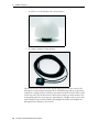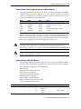
1
USER GUIDE Resolution T GPS Embedded Board ® USER GUIDE Resolution T® GPS Embedded Board Version 2.0 Revision B Part Number 54655-05-ENG August 2009 F Corporate Office Trimble Navigation Limited Component Technologies 935 Stewart Drive Sunnyvale, CA 94085 U.S.A. Phone: 1-800-767-4822 www.trimble.com Support Offices Trimble Navigation Limited Component Technologies 935 Stewart Drive Sunnyvale, CA 94085 U.S.A. Phone: 1-800-767-4822 Legal Notices Copyright and Trademarks © 2005–2009, Trimble Navigation Limited. Trimble, the Globe & Triangle logo, and Resolution T are trademarks of Trimble Navigation Limited, registered in the United States and in other countries. Bullet is a trademark of Trimble Navigation Limited. Microsoft and Windows are either registered trademarks or trademarks of Microsoft Corporation in the United States and/or other countries. All other trademarks are the property of their respective owners. Release Notice This is the August 2009 release (Revision B) of the Resolution T GPS Embedded Board User Guide, part number 54655-05-ENG. LIMITED WARRANTY TERMS AND CONDITIONS Product Limited Warranty Subject to the following terms and conditions, Trimble Navigation Limited (“Trimble”) warrants that for a period of one (1) year from date of purchase this Trimble product (the “Product”) will substantially conform to Trimble's publicly available specifications for the Product and that the hardware and any storage media components of the Product will be substantially free from defects in materials and workmanship. Product Software Product software, whether built into hardware circuitry as firmware, provided as a standalone computer software product, embedded in flash memory, or stored on magnetic or other media, is licensed solely for use with or as an integral part of the Product and is not sold. If accompanied by a separate end user license agreement (“EULA”), use of any such software will be subject to the terms of such end user license agreement (including any differing limited warranty terms, exclusions, and limitations), which shall control over the terms and conditions set forth in this limited warranty. Software Fixes During the limited warranty period you will be entitled to receive such Fixes to the Product software that Trimble releases and makes commercially available and for which it does not charge separately, subject to the procedures for delivery to purchasers of Trimble products generally. If you have purchased the Product from an authorized Trimble dealer rather than from Trimble directly, Trimble may, at its option, forward the software Fix to the Trimble dealer for final distribution to you. Minor Updates, Major Upgrades, new products, or substantially new software releases, as identified by Trimble, are expressly excluded from this update process and limited warranty. Receipt of software Fixes or other enhancements shall not serve to extend the limited warranty period. For purposes of this warranty the following definitions shall apply: (1) “Fix(es)” means an error correction or other update created to fix a previous software version that does not substantially conform to its Trimble specifications; (2) “Minor Update” occurs when enhancements are made to current features in a software program; and (3) “Major Upgrade” occurs when significant new features are added to software, or when a new product containing new features replaces the further development of a current product line. Trimble reserves the right to determine, in its sole discretion, what constitutes a Fix, Minor Update, or Major Upgrade. Warranty Remedies If the Trimble Product fails during the warranty period for reasons covered by this limited warranty and you notify Trimble of such failure during the warranty period, Trimble will repair OR replace the nonconforming Product with new, equivalent to new, or reconditioned parts or Product, OR refund the Product purchase price paid by you, at Trimble’s option, upon your return of the Product in accordance with Trimble's product return procedures then in effect. How to Obtain Warranty Service To obtain warranty service for the Product, please contact your local Trimble authorized dealer. Alternatively, you may contact Trimble to request warranty service at +1-408-481-6940 (24 hours a day) or e-mail your request to [email protected]. Please be prepared to provide: – your name, address, and telephone numbers – proof of purchase – a copy of this Trimble warranty – a description of the nonconforming Product including the model number – an explanation of the problem 2 Resolution T GPS Embedded Board User Guide The customer service representative may need additional information from you depending on the nature of the problem. Warranty Exclusions and Disclaimer This Product limited warranty shall only apply in the event and to the extent that (a) the Product is properly and correctly installed, configured, interfaced, maintained, stored, and operated in accordance with Trimble's applicable operator's manual and specifications, and; (b) the Product is not modified or misused. This Product limited warranty shall not apply to, and Trimble shall not be responsible for, defects or performance problems resulting from (i) the combination or utilization of the Product with hardware or software products, information, data, systems, interfaces, or devices not made, supplied, or specified by Trimble; (ii) the operation of the Product under any specification other than, or in addition to, Trimble's standard specifications for its products; (iii) the unauthorized installation, modification, or use of the Product; (iv) damage caused by: accident, lightning or other electrical discharge, fresh or salt water immersion or spray (outside of Product specifications); or exposure to environmental conditions for which the Product is not intended; (v) normal wear and tear on consumable parts (e.g., batteries); or (vi) cosmetic damage. Trimble does not warrant or guarantee the results obtained through the use of the Product, or that software components will operate error free. NOTICE REGARDING PRODUCTS EQUIPPED WITH TECHNOLOGY CAPABLE OF TRACKING SATELLITE SIGNALS FROM SATELLITE BASED AUGMENTATION SYSTEMS (SBAS) (WAAS/EGNOS, AND MSAS), OMNISTAR, GPS, MODERNIZED GPS OR GLONASS SATELLITES, OR FROM IALA BEACON SOURCES: TRIMBLE IS NOT RESPONSIBLE FOR THE OPERATION OR FAILURE OF OPERATION OF ANY SATELLITE BASED POSITIONING SYSTEM OR THE AVAILABILITY OF ANY SATELLITE BASED POSITIONING SIGNALS. THE FOREGOING LIMITED WARRANTY TERMS STATE TRIMBLE’S ENTIRE LIABILITY, AND YOUR EXCLUSIVE REMEDIES, RELATING TO THE TRIMBLE PRODUCT. EXCEPT AS OTHERWISE EXPRESSLY PROVIDED HEREIN, THE PRODUCT, AND ACCOMPANYING DOCUMENTATION AND MATERIALS ARE PROVIDED “AS-IS” AND WITHOUT EXPRESS OR IMPLIED WARRANTY OF ANY KIND, BY EITHER TRIMBLE OR ANYONE WHO HAS BEEN INVOLVED IN ITS CREATION, PRODUCTION, INSTALLATION, OR DISTRIBUTION, INCLUDING, BUT NOT LIMITED TO, THE IMPLIED WARRANTIES OF MERCHANTABILITY AND FITNESS FOR A PARTICULAR PURPOSE, TITLE, AND NONINFRINGEMENT. THE STATED EXPRESS WARRANTIES ARE IN LIEU OF ALL OBLIGATIONS OR LIABILITIES ON THE PART OF TRIMBLE ARISING OUT OF, OR IN CONNECTION WITH, ANY PRODUCT. BECAUSE SOME STATES AND JURISDICTIONS DO NOT ALLOW LIMITATIONS ON DURATION OR THE EXCLUSION OF AN IMPLIED WARRANTY, THE ABOVE LIMITATION MAY NOT APPLY OR FULLY APPLY TO YOU. Limitation of Liability TRIMBLE'S ENTIRE LIABILITY UNDER ANY PROVISION HEREIN SHALL BE LIMITED TO THE AMOUNT PAID BY YOU FOR THE PRODUCT. TO THE MAXIMUM EXTENT PERMITTED BY APPLICABLE LAW, IN NO EVENT SHALL TRIMBLE OR ITS SUPPLIERS BE LIABLE FOR ANY INDIRECT, SPECIAL, INCIDENTAL, OR CONSEQUENTIAL DAMAGE WHATSOEVER UNDER ANY CIRCUMSTANCE OR LEGAL THEORY RELATING IN ANYWAY TO THE PRODUCTS, SOFTWARE AND ACCOMPANYING DOCUMENTATION AND MATERIALS, (INCLUDING, WITHOUT LIMITATION, DAMAGES FOR LOSS OF BUSINESS PROFITS, BUSINESS INTERRUPTION, LOSS OF DATA, OR ANY OTHER PECUNIARY LOSS), REGARDLESS OF WHETHER TRIMBLE HAS BEEN ADVISED OF THE POSSIBILITY OF ANY SUCH LOSS AND REGARDLESS OF THE COURSE OF DEALING WHICH DEVELOPS OR HAS DEVELOPED BETWEEN YOU AND TRIMBLE. BECAUSE SOME STATES AND JURISDICTIONS DO NOT ALLOW THE EXCLUSION OR LIMITATION OF LIABILITY FOR CONSEQUENTIAL OR INCIDENTAL DAMAGES, THE ABOVE LIMITATION MAY NOT APPLY OR FULLY APPLY TO YOU. PLEASE NOTE: THE ABOVE TRIMBLE LIMITED WARRANTY PROVISIONS WILL NOT APPLY TO PRODUCTS PURCHASED IN THOSE JURISDICTIONS (E.G., MEMBER STATES OF THE EUROPEAN ECONOMIC AREA) IN WHICH PRODUCT WARRANTIES ARE THE RESPONSIBILITY OF THE LOCAL TRIMBLE AUTHORIZED DEALER FROM WHOM THE PRODUCTS ARE ACQUIRED. IN SUCH A CASE, PLEASE CONTACT YOUR LOCAL TRIMBLE AUTHORIZED DEALER FOR APPLICABLE WARRANTY INFORMATION. Official Language THE OFFICIAL LANGUAGE OF THESE TERMS AND CONDITIONS IS ENGLISH. IN THE EVENT OF A CONFLICT BETWEEN ENGLISH AND OTHER LANGUAGE VERSIONS, THE ENGLISH LANGUAGE SHALL CONTROL. Notice to Our European Union Customers For product recycling instructions and more information, please go to www.trimble.com/ev.shtml. Recycling in Europe: To recycle Trimble WEEE (Waste Electrical and Electronic Equipment, products that run on electrical power.), Call +31 497 53 24 30, and ask for the "WEEE Associate". Or, mail a request for recycling instructions to: Trimble Europe BV c/o Menlo Worldwide Logistics Meerheide 45 5521 DZ Eersel, NL Safety Information Warnings and Cautions An absence of specific alerts does not mean that there are no safety risks involved. Always follow the instructions that accompany a Warning or Caution. The information they provide is intended to minimize the risk of personal injury and/or damage to the equipment. In particular, observe safety instructions that are presented in the following formats: C WARNING – A Warning alerts you to a likely risk of serious injury to your person and/or damage to the equipment. C CAUTION – A Caution alerts you to a possible risk of damage to the equipment and/or loss of data. Operation and storage C WARNING – The Resolution T GPS receiver is ready to accept TSIP commands approximately 2.1 seconds after power-up. If a command is sent to the receiver within this 2.1 second window, the receiver will ignore the command. The Resolution T GPS receiver will not respond to commands sent within the 2.1 second window and will discard any associated command data. C WARNING – Operating or storing the Resolution T GPS timing receiver outside the specified temperature range can damage it. For more information, see the product specifications on the data sheet. Routing any cable C CAUTION – Be careful not to damage the cable. Take care to avoid sharp bends or kinks in the cable, hot surfaces (for example, exhaust manifolds or stacks), rotating or reciprocating equipment, sharp or abrasive surfaces, door and window jambs, and corrosive fluids or gases. Resolution T GPS Embedded Board User Guide 3 Safety Information AC adaptor safety An international adaptor kit is provided with the Resolution T Starter Kit. C 4 WARNING – Using an incorrect AC adaptor can damage your product and may void your warranty. To use AC adaptors safely: – Use only the AC adaptor intended for the Resolution T GPS timing receiver. Using any other AC adaptor can damage your product and may void your warranty. – Do not use the AC adaptor with any other product. – Make certain that the input voltage on the adaptor matches the voltage and frequency in your location. – Make certain that the adaptor has prongs compatible with your outlets. – AC adaptors are designed for indoor use only. Avoid using the AC adaptor in wet outdoor areas. – Unplug the AC adaptor from power when not in use. – Do not short the output connector. – There are no user-serviceable parts in this product. – Should damage to the AC adaptor occur, replace it with a new Trimble AC adaptor. Resolution T GPS Embedded Board User Guide Contents Safety Information . . . . . . . . . . . . . . . . . . . . . . . . . . . . . . . . 3 Warnings and Cautions Operation and storage . Routing any cable . . . . AC adaptor safety . . . . 1 . . . . . . . . . . . . . . . . . . . . . . . . . . . . . . . . . . . . . . . . . . . . . . . . . . . . . . . . . . . . . . . . . . . . . . . . . . . . . . . . . . . . . . . . . . . . . . . . . . . . . . . . . . . . . . . . . . . . . . . . . . . . . . . . . . . . . . . . . . . . . . . . . . . . . . . . . . . . . . . . . . . . . . . . . . . . . . . . . . . . . . . . . . . . . . . . . . . . . . . . . . . . . . . . . . . . . . . . . . . . . . . . . . . . . . . . . . . . . . . . . . . . . . . . . . . . . . . . . . . . . . . . . . . . . . . . . . . . . . . . . . . . . . . . . . . . . . . . . . . . . . . . . . . . . . . . . . . . . . . . . . . . . . 3 3 3 4 . . . . . . . . . . . . . . . . . . . . . . . . . . . . . . . . . . . . . . . . . . . . . . . . . . . . . . . . . . . . . . . . . . . . . . . . . . . . . . . . . . . . . . . . . . . . . . . . . . . . . . . . . . . . . . . . . . . . . . . . . . . . . . . . . . . . 10 10 10 10 11 11 Setting up the Resolution T Starter Kit . . . . . . . . . . . . . . . . . . . . 12 System requirements. . . . . . . . . . . . . . . . . . . . . . . . . Hardware . . . . . . . . . . . . . . . . . . . . . . . . . . . . Computer. . . . . . . . . . . . . . . . . . . . . . . . . . . . System software. . . . . . . . . . . . . . . . . . . . . . . . Removing the Resolution T module from the motherboard Timing receiver performance . . . . . . . . . . . . . . . . . . . Interface protocols . . . . . . . . . . . . . . . . . . . . . . . . . . Resolution T starter kit . . . . . . . . . . . . . . . . . . . . . . . Starter kit interface unit . . . . . . . . . . . . . . . . . . Power . . . . . . . . . . . . . . . . . . . . . . . . . . . . . . . . . . AC/DC power converter . . . . . . . . . . . . . . . . . . Setting up the starter kit. . . . . . . . . . . . . . . . . . . . . . . Setting up the software toolkit . . . . . . . . . . . . . . . . . . . 3 . . . . Introduction . . . . . . . . . . . . . . . . . . . . . . . . . . . . . . . . . . . . 9 Operation . . . . . . . Timing features . . . Starter kit . . . . . . . Use and care . . . . . Technical assistance Your comments . . . 2 . . . . . . . . . . . . . . . . . . . . . . . . . . . . . . . . . . . . . . . . . . . . . . . . . . . . . . . . . . . . . . . . . . . . . . . . . . . . . . . . . . . . . . . . . . . . . . . . . . . . . . . . . . . . . . . . . . . . . . . . . . . . . . . . . . . . . . . . . . . . . . . . . . . . . . . . . . . . . . . . . . . . . . . . . . . . . . . . . . . . . . . . . . . . . . . . . . . . . . . . . . . . . . . . . . . . . . . . . . . . . . . . . . . . . . . . . . . . . . . . . . . . . . . . . . . . . . . . . . . . . . . . . . . . . . . . . . . . . . . . . . . . . . . . . . 13 13 13 13 13 14 15 15 16 18 18 19 20 Hardware Integration . . . . . . . . . . . . . . . . . . . . . . . . . . . . . . 22 Resolution T board . . . . . . . . . . . . . . . . Connectors . . . . . . . . . . . . . . . . . . . . . Digital IO/Power connector . . . . . . Mating connectors . . . . . . . . . . . . RF connector . . . . . . . . . . . . . . . Antenna options . . . . . . . . . . . . . Digital IO/Power connector pin-out . Power requirements . . . . . . . . . . . . . . . Serial interface . . . . . . . . . . . . . . . . . . . Pulse-per-second (PPS) . . . . . . . . . . . . . Mounting . . . . . . . . . . . . . . . . . . . . . . . . . . . . . . . . . . . . . . . . . . . . . . . . . . . . . . . . . . . . . . . . . . . . . . . . . . . . . . . . . . . . . . . . . . . . . . . . . . . . . . . . . . . . . . . . . . . . . . . . . . . . . . . . . . . . . . . . . . . . . . . . . . . . . . . . . . . . . . . . . . . . . . . . . . . . . . . . . . . . . . . . . . . . . . . . . . . . . . . . . . . . . . . . . . . . . . . . . . . . . . . . . . . . . . . . . . . . . . . . . . . . . . . . . . . . . . . . . . . . . . . . . . . . . . . . . . . . . . . . . . . . . . . . . . . . . . . . . . . . . . . . . . . . . . . . . . . . . . . . . . . . . . . . . . . . . . . . . . . . . . . . . . . . . . . . . . . . . . . . . . . . . . . . . . . . . . 23 23 23 23 23 24 24 24 25 25 25 Resolution T GPS Embedded Board User Guide 5 Contents GPS antenna . . . . . . . . . . . . . . . . . . . . . . . . . . . . . . . . . . . . . . . . . . . . . . . . . . . . 25 4 Software Interface. . . . . . . . . . . . . . . . . . . . . . . . . . . . . . . . 27 Start-up . . . . . . . . . . . . . . . . . . . . . . . . . . . . . . Communicating with the receiver . . . . . . . . . . . . . Software tools . . . . . . . . . . . . . . . . . . . . . . Port configuration . . . . . . . . . . . . . . . . . . . Port protocol and data output options. . . . . . . . . . . Protocol configuration and interface . . . . . . . NMEA 0183 Protocol and Data Output Options 5 . . . . . . . . . . . . . . . . . . . . . . . . . . . . . . . . . . . . . . . . . . . . . . . . . . . . . . . . . . . . . . . . . . . . . . . . . . . . . . . . . . . . . . . . . . . . . . . . . . . . . . . . . . . . . . . . . . . . . . . . . . . . . . . . . . . . . . . . . . . . . . . . . . . . . . . . . . . . . . . . . . . . . . . . . . . . . . . . . . . . . . . . . . . . . . . . . . . . . . . . . . . . . . . . . . . . . . . . . . . . . . . . . . . . . . . . . . . . . . . . . . . . . . . . . . . . . . . . . . . . . . . . . . . . . . . . . . . . . . . . . . . . . . . . . . . . . . . . . . . . . . . . . . . . . . . . . . . . . . . . . . . . . . . . . . . . . . . . . . . . . . . . . . . . . . . . . . . . . . . . . . . . . . . . . . . . . . . . . . . . . . . . . . . . . . . . . . . . . . . . . . . . . . . . . . . . . . . . . . . . . . . . . . . . . . . . . . . . . . . . . . . . . . . . . 28 28 28 28 29 29 30 . . . . . . . . . . . . . . . . . . . . . . . . . . . . . . . . . . . . . . . . . . . . . . . . . . . . . . . . . . . . . . . . . . . . . . . . . . . . . . . . . . . . . . . . . . . . . . . . . . . . . . . . . . . . 32 32 32 33 34 36 36 37 37 38 38 39 Trimble Standard Interface Protocol. . . . . . . . . . . . . . . . . . . . . . 40 Introduction . . . . . . . . . . . . . . . . . . . . . . . . . . . . . . . . . . . . . . . . . . . Interface scope . . . . . . . . . . . . . . . . . . . . . . . . . . . . . . . . . . . . . Automatic output packets . . . . . . . . . . . . . . . . . . . . . . . . . . . . . . Customizing operations parameters . . . . . . . . . . . . . . . . . . . . . . . . . . . . Factory default settings . . . . . . . . . . . . . . . . . . . . . . . . . . . . . . . . Packet I/O control . . . . . . . . . . . . . . . . . . . . . . . . . . . . . . . . . . . Serial port configuration . . . . . . . . . . . . . . . . . . . . . . . . . . . . . . . Timing outputs . . . . . . . . . . . . . . . . . . . . . . . . . . . . . . . . . . . . . Accurate position. . . . . . . . . . . . . . . . . . . . . . . . . . . . . . . . . . . . Self-survey . . . . . . . . . . . . . . . . . . . . . . . . . . . . . . . . . . . . . . . . Packets output at startup . . . . . . . . . . . . . . . . . . . . . . . . . . . . . . . . . . . Report packets: Resolution T to User. . . . . . . . . . . . . . . . . . . . . . . . . . . . Command Packets: User to Resolution T . . . . . . . . . . . . . . . . . . . . . . . . . Packet structure . . . . . . . . . . . . . . . . . . . . . . . . . . . . . . . . . . . . . . . . . Packet descriptions . . . . . . . . . . . . . . . . . . . . . . . . . . . . . . . . . . . . . . . Command Packet 0x1C: Firmware Version 01 . . . . . . . . . . . . . . . . . . Report Packet 0x1C: 81 . . . . . . . . . . . . . . . . . . . . . . . . . . . . . . . . Command Packet 0x1C: 03 – hardware component version information. Report Packet 0x1C: 83 – hardware component version information . . . 6 . . . . . . . System Operation . . . . . . . . . . . . . . . . . . . . . . . . . . . . . . . . 31 Operation . . . . . . . . . . . . . . . . . . . . . Start-up . . . . . . . . . . . . . . . . . . Automatic operation. . . . . . . . . . Tracking modes . . . . . . . . . . . . . PPS quantization error. . . . . . . . . . . . . Data communication . . . . . . . . . . . . . GPS timing . . . . . . . . . . . . . . . . Timing operation . . . . . . . . . . . . Using Resolution T in mobile applications Customizing operations . . . . . . . . . . . . Configuration parameters . . . . . . System architecture . . . . . . . . . . . . . . A . . . . . . . Resolution T GPS Embedded Board User Guide . . . . . . . . . . . . . . . . . . . . . . . . . . . . . . . . . . . . . . . . . . . . . . . . . . . . . . . . . . . . . . . . . . . . . . . . . . . . . . . . . . . . . . . . . . . . . . . . . . . . . . . . . . . . . . . . . . . . . . . . . . . . . . . . . . . . . . . . . . . . . . . . . . . . . . . . . . . . . . . . . . . . . . . . . . . 41 41 41 42 42 43 43 43 43 44 44 44 45 46 47 47 47 48 48 Contents Command Packet 0x1E: Clear RAM then Reset . . . . . . . . . . . . . . . . . . . . . . Command Packet 0x1F: Request Software Version . . . . . . . . . . . . . . . . . . . . Command Packet 0x24: Request GPS Satellite Selection . . . . . . . . . . . . . . . . Command Packet 0x25: Initiate Hot Reset & Self Test . . . . . . . . . . . . . . . . . . Command Packet 0x27: Request Signal Levels . . . . . . . . . . . . . . . . . . . . . . Command Packet 0x31: Accurate Initial Position (XYZ Cartesian ECEF). . . . . . Command Packet 0x32: Accurate Initial Position (Latitude, Longitude, Altitude) Command Packet 0x34: Satellite Select For One-Satellite Mode . . . . . . . . . . . Command Packet 0x35: Set or Request I/O Options . . . . . . . . . . . . . . . . . . . Command Packet 0x37: Request Status and Values of Last Position . . . . . . . . . Command Packet 0x38: Request Satellite System Data . . . . . . . . . . . . . . . . . Command Packet 0x39: Set or Request SV Disable and Health Use . . . . . . . . . Command Packet 0x3A: Request last raw Measurement . . . . . . . . . . . . . . . . Command Packet 0x3C: Request Current Satellite Tracking Status . . . . . . . . . Command Packet 0x7A: Set or Request NMEA Interval and Message Mask . . . . Report Packet 0x7B: Set NMEA Message Output . . . . . . . . . . . . . . . . . . . . . Report Packet 0x42: Single-precision Position Fix . . . . . . . . . . . . . . . . . . . . Report Packet 0x43 Velocity Fix, XYZ ECEF . . . . . . . . . . . . . . . . . . . . . . . . Report Packet 0x45: Software Version Information . . . . . . . . . . . . . . . . . . . . Report Packet 0x47: Signal Level for All Satellites Tracked . . . . . . . . . . . . . . . Report Packet 0x4A: Single Precision LLA Position Fix . . . . . . . . . . . . . . . . . Report Packet 0x55 I/O Options . . . . . . . . . . . . . . . . . . . . . . . . . . . . . . . Report Packet 0x56: Velocity Fix, East-North-Up (ENU). . . . . . . . . . . . . . . . . Report Packet 0x57: Information about Last Computed Fix . . . . . . . . . . . . . . Report Packet 0x58: GPS System Data/Acknowledge from Receiver . . . . . . . . . Report Packet 0x59: Status of Satellite Disable or Ignore Health . . . . . . . . . . . Report Packet 0x5A: Raw Data Measurement Data . . . . . . . . . . . . . . . . . . . Report Packet 0x5C: Satellite Tracking Status . . . . . . . . . . . . . . . . . . . . . . . Report Packet 0x6D: All-in-View Satellite Selection . . . . . . . . . . . . . . . . . . . Report Packet 0x83: Double Precision XYZ. . . . . . . . . . . . . . . . . . . . . . . . . Report Packet 0x84: Double Precision LLA Position Fix and Bias Information . . Command Packet 0xBB: Set Primary Configuration . . . . . . . . . . . . . . . . . . . Command Packet 0xBC: Set Port Configuration . . . . . . . . . . . . . . . . . . . . . TSIP Superpackets . . . . . . . . . . . . . . . . . . . . . . . . . . . . . . . . . . . . . . . . . . . . Command Packet 0x8E-01: Configure Raw GPS Data Output . . . . . . . . . . . . . Command Packet 0x8E-15: Request Current Datum Values . . . . . . . . . . . . . . Command Packet 0x8E-26: Write Receiver Configuration to Flash ROM . . . . . . Command Packet 0x8E-41: Request Manufacturing Parameters . . . . . . . . . . . Command Packet 0x8E-42: Stored Production Parameters . . . . . . . . . . . . . . Command Packet 0x8E-4A: Set PPS Characteristics . . . . . . . . . . . . . . . . . . . Command Packet 0x8E-4E: Set PPS output option . . . . . . . . . . . . . . . . . . . . Command Packet 0x8E-A2: UTC/GPS Timing . . . . . . . . . . . . . . . . . . . . . . Command Packet 0x8E-A4: Test Modes. . . . . . . . . . . . . . . . . . . . . . . . . . . Command Packet 0x8E-A5: Packet Broadcast Mask . . . . . . . . . . . . . . . . . . . . . . . . . . . . . . . . . . . . . . . . . . . . . . . . . . . . . . . . . . . . . . . . . . . . . . . . . . . . . . . . . . . . . . . . . . . . . . . . . . . . . . . . . . . . . . . . . . . . . . . . . . . . . . . . . . . . . . . . . . . . . . . . . . . . . . . . . . . . . . . . . . . . . . . . . . . . . . . . . . . . . . . . . . . . . . . . . . . 48 49 49 50 50 50 51 51 51 53 53 53 54 54 54 55 55 55 56 56 57 57 58 59 59 62 63 63 64 65 65 66 67 68 68 69 69 69 69 69 70 70 71 72 Resolution T GPS Embedded Board User Guide 7 Contents Command Packet 0x8E-A6: Self-Survey Command . . . . . . . . . . . . Command Packet 0x8E-A9: Self-Survey Parameters . . . . . . . . . . . . Report Packet 0x8F-01: Report Raw GPS Subframes . . . . . . . . . . . . Report Packet 0x8F-15: Current Datum Values . . . . . . . . . . . . . . . Report Packet 0x8F-41: Stored Manufacturing Operating Parameters. Report Packet 0x8F-42: Stored Production Parameters . . . . . . . . . . Report Packet 0x8F-4A: Set PPS Characteristics . . . . . . . . . . . . . . Report Packet 0x8F-4E: PPS Output . . . . . . . . . . . . . . . . . . . . . . Report Packet 0x8F-A2: UTC/GPS Timing . . . . . . . . . . . . . . . . . . Report Packet 0x8F-A5: Packet Broadcast Mask . . . . . . . . . . . . . . Report Packet 0x8F-A9: Self-Survey Parameters . . . . . . . . . . . . . . Report Packet 0x8F-AB: Primary Timing Packet . . . . . . . . . . . . . . Broadcast Control: Packet 8F-AB, Mask 0, Bit 0 . . . . . . . . . . . . . . Report Packet 0x8F-AC: Supplemental Timing Packet . . . . . . . . . . Unused or miscellaneous packets. . . . . . . . . . . . . . . . . . . . . . . . . . . . Report Packet 0x13: Unparsable Packet . . . . . . . . . . . . . . . . . . . . Report Packet 0x13: Data Format . . . . . . . . . . . . . . . . . . . . . . . Legacy packets (unused) . . . . . . . . . . . . . . . . . . . . . . . . . . . . . . . . . Report Packet Ox54: Bias and Bias Rate. . . . . . . . . . . . . . . . . . . . Report Packet Ox46: Health of Receiver . . . . . . . . . . . . . . . . . . . . Report Packet Ox41: GPS Time . . . . . . . . . . . . . . . . . . . . . . . . . Report Packet 0x4B: Machine Code ID and Additional Status . . . . . . B . . . . . . . . . . . . . . . . . . . . . . . . . . . . . . . . . . . . . . . . . . . . . . . . . . . . . . . . . . . . . . . . . . . . . . . . . . . . . . . . . . . . . . . . . . . . . . . . . . . . . . . . . . . . . . . . . . . . . . . . . . . . . . . . . . . . . . . . . . . . . . . . . . . . . . . . . . . . . . . . . . . . . . . . . . . . . . . . . . . . . . . . . . . . . . . . . . . . . . . . . . . . . . . . . . . . . . . . . . . . 73 73 74 75 75 76 76 76 76 76 77 77 78 78 82 82 82 82 82 82 82 82 NMEA 0183 Protocol . . . . . . . . . . . . . . . . . . . . . . . . . . . . . . . 83 Introduction . . . . . . . . . . . . . . . . . . . . . . . . . . . . . . . . . . . NMEA 0183 communication interface. . . . . . . . . . . . . . . . . . . NMEA 0183 message structure . . . . . . . . . . . . . . . . . . . . . . . Field definitions . . . . . . . . . . . . . . . . . . . . . . . . . . . . . . . . . NMEA 0183 message options . . . . . . . . . . . . . . . . . . . . . . . . NMEA 0183 message formats . . . . . . . . . . . . . . . . . . . . . . . . GGA-GPS Fix Data . . . . . . . . . . . . . . . . . . . . . . . . . . . GLL - Geographic Position - Latitude/Longitude . . . . . . . . GSA - GPS DOP and Active Satellites . . . . . . . . . . . . . . . GSV - GPS Satellites in View . . . . . . . . . . . . . . . . . . . . . RMC - Recommended Minimum Specific GPS/Transit Data VTG - Track Made Good and Ground Speed. . . . . . . . . . . ZDA - Time & Date. . . . . . . . . . . . . . . . . . . . . . . . . . . Exception behavior . . . . . . . . . . . . . . . . . . . . . . . . . . . . . . . Interruption of GPS signal . . . . . . . . . . . . . . . . . . . . . . C . . . . . . . . . . . . . . . . . . . . . . . . . . . . . . . . . . . . . . . . . . . . . . . . . . . . . . . . . . . . . . . . . . . . . . . . . . . . . . . . . . . . . . . . . . . . . . . . . . . . . . . . . . . . . . . . . . . . . . . . . . . . . . . . . . . . . . . . . . . . . . . . . . . . . . . . . . . . . . . . . . . . . . . . . . . . . . . . . . . . . . . . . . . . . . . . . . . . . . . . . . . . . . . . . . . . . . . . . . . . . . . . . . . . . . . . . . . . . . . . . . . . . . . . . . . . . . . . . . . . . . . . . . . . . . . . . . . . . 84 84 85 85 86 87 87 88 88 89 89 90 90 91 91 Specifications. . . . . . . . . . . . . . . . . . . . . . . . . . . . . . . . . . . 92 Mechanical specification . . . . . . . . . . . . . . . . . . . . . . . . . . . . . . . . . . . . . . . . . . . . 93 8 Resolution T GPS Embedded Board User Guide CHAPTER 1 Introduction In this chapter: Operation Timing features Starter kit Use and care Technical assistance Your comments 1 The Resolution T GPS Embedded Board User Guide describes how to integrate and operate the Resolution T ® GPS timing receiver. The instructions in this manual assume that you know how to use the primary functions of a Microsoft® Windows® operating system. The Trimble Resolution T embedded timing board, is a full featured, 12 channel, parallel tracking GPS receiver. The receiver is designed to operate on the L1 (1575.42 MHz) frequency, providing standard position service (SPS) using Coarse Acquisition (C/A) code. The Trimble Resolution T is designed for 3.3 V prime power and provides a separate pin on the I/O connector for powering the antenna with a user supplied voltage from 3.0 V to 5.5 V (antenna dependent). For more information on GPS, go to http://www.trimble.com/gps/index.shtml. Resolution T GPS Embedded Board User Guide 9 1 Introduction Operation The Resolution T automatically initiates a self-survey upon acquisition of GPS satellites. When the survey is completed, the receiver switches into the Overdetermined Timing Mode. In this mode, the reference position from the self survey is maintained in memory and the receiver solves only for clock error and clock bias. The receiver provides for both Position and Time Receiver Autonomous Integrity Monitoring which allows the receiver to self determine a position change or to remove a satellite providing incorrect information from the timing solution. Note – To offset the delay inherent in the RF cable from the antenna to the receiver and further improve the accuracy, determine the length of the cable and enter the offset based on the specific cable type. Timing features The timing features of the Resolution T GPS timing receiver include the following: • Automatic self survey • Overdetermined timing mode • Single satellite timing mode • Timing Superpackets • TRAIM (Timing Receiver Autonomous Integrity Monitoring) • Position integrity • Cable-delay compensation • Accuracy <15 ns (1 σ). Starter kit The starter kit makes it simple to evaluate the Resolution T receiver’s performance. It can be used as a platform for configuring the receiver software or as a platform for troubleshooting your design. For a complete description of the starter kit, see Resolution T starter kit, page 15. Use and care The Resolution T GPS timing receiver is a high-precision electronic instrument and should be treated with reasonable care. C 10 CAUTION – There are no user-serviceable parts inside the Resolution T and any modification to the unit by the user voids the warranty. Resolution T GPS Embedded Board User Guide 1 Introduction Technical assistance If you have a problem and cannot find the information you need in the product documentation, contact the Trimble Technical Assistance Center at 800-767-4822 or email [email protected]. Your comments Your feedback about the supporting documentation helps us to improve it with each revision. Email your comment to [email protected]. Resolution T GPS Embedded Board User Guide 11 CHAPTER 2 Setting up the Resolution T Starter Kit In this chapter: System requirements Timing receiver performance Interface protocols Resolution T starter kit Power Setting up the starter kit Setting up the software toolkit 2 This chapter describes the elements of the Resolution T starter kit and how to set it up. The hardware integration is described in Chapter 3, Hardware Integration. Resolution T GPS Embedded Board User Guide 12 2 Setting up the Resolution T Starter Kit System requirements Hardware • The Trimble Resolution T Starter Kit, see page 15. • User-provided connectors and extension cords to connect the Resolution T to the computer, antenna interface, and other devices as required. • +24 VDC power supply • User-provided equipment to analyze the 10 MHz output frequency and the 1 PPS accuracy, and a BNC connector to connect them to the Resolution T module. • User-provided connectors and extension cords to connect the Resolution T to the computer, antenna interface, and other devices as required. Computer • • An office computer running a version of the Windows® operating system (Windows 2000 or later) The computer must have one of the following service packs installed: – Service Pack 2, for Windows Vista® or Windows XP – Service Pack 4, for Windows 2000 System software • Monitor software. The software is used to monitor the GPS performance of the Resolution T and to change its settings. The software is compatible with the Windows 95, 98, 2000, and XP operating systems and with the Windows Vista operating system. • Trimble Standard Interface Protocol (TSIP). This consists of command packets and report packets. See Appendix A, Trimble Standard Interface Protocol Removing the Resolution T module from the motherboard The Resolution T GPS receiver is secured to the motherboard standoffs with Phillips head screws, allowing for removal and integration with the user's application. Follow these steps to remove the receiver from the motherboard: 1. Disconnect power to the enclosure. 2. Remove base plate and unplug the RF cable from the receiver. 3. Use a small Phillips screwdriver to remove the securing hardware which holds the Resolution T GPS receiver to the motherboard. Resolution T GPS Embedded Board User Guide 13 2 Setting up the Resolution T Starter Kit 4. C Gently rock the board loose from the motherboard I/O connector. WARNING – Before opening the interface unit, disconnect the unit from any external power source and confirm that both you and your work surface are properly grounded for ESD protection. The Resolution T is designed for embedded applications. The digital I/O lines and power lines are not designed with additional ESD protection like a stand-alone receiver would be. Use standard CMOS ESD handling precautions when removing and installing the receiver module. Timing receiver performance The Resolution T GPS timing receiver is a complete 12-channel, parallel tracking, GPS receiver, designed to operate with the L1 frequency, Standard Position Service, Coarse Acquisition code. The receiver is designed in a single board format, specially adapted for timing applications where reliability, performance, and ease of integration are desired. The receiver features Trimble's improved signal processing code, a high-gain RF section for compatibility with standard active gain GPS antennas, and a CMOS level pulse-per-second (PPS) output for timing and synchronization applications. Timing applications are assumed to be static. The special timing software used with the Resolution T receiver configures the unit into an automatic self survey mode at start up. The receiver will average position fixes for a specified time (one per second) and at the end of this period will save this reference location. At this time the receiver will go into an Overdetermined Clock mode and no longer solve for position but only for clock error and clock bias using all of the available satellites. This provides an accuracy of less than 15ns (1 Sigma) for the 1PPS output. User settings such as port parameters and NMEA settings can be stored in the receiver's non-volatile ( flash) memory. These settings are retained without main power. The Resolution T receiver has a single configurable serial I/O communication port. Note – When customizing port assignments or characteristics, confirm that your changes do not affect your ability to communicate with the receiver. 14 Resolution T GPS Embedded Board User Guide 2 Setting up the Resolution T Starter Kit Interface protocols The Resolution T receiver operates using one of two protocols: protocol selection and port characteristics are user configurable. Note – The factory default setting for the I/O port is TSIP bidirectional. • TSIP (Trimble Standard Interface Protocol) is a powerful binary packet protocol that allows the system designer maximum configuration control over the GPS receiver for optimum performance in timing applications. TSIP supports multiple commands and their associated response packets for use in configuring the Resolution T receiver to meet user requirements. • NMEA 0183 (National Marine Electronics Association) is an industry standard protocol common to marine applications. NMEA provides direct compatibility with other NMEA-capable devices such as chart plotters, radar, etc. The Resolution T receiver supports the ZDA NMEA message for GPS timing. You can select other NMEA messages and output rates as required. Resolution T starter kit The Resolution T GPS receiver is available in a Starter Kit or as an individual receiver and associated antenna. The Starter Kit includes all the components necessary to quickly test and integrate the receiver: Resolution T GPS Embedded Board User Guide 15 2 Setting up the Resolution T Starter Kit The starter kit includes the Resolution T timing module, mounted on an interface motherboard in a durable metal enclosure. The motherboard accepts 9 – 32 VDC power and provides regulated +3.3 V power to the Resolution T receiver. The motherboard also contains: • Two antenna options: – Bullet™ III GPS antenna, 5 V, F connector – Miniature magnetic mount antenna • 50 feet (20 m) RG-59 antenna cable, terminated with F connectors (F-F) • Interface cable, USB • AC/DC power supply adapter: • – Input: 100 – 240 VAC – Output: 24 VDC SMB to F adapter cable (RG-316 antenna transition cable) Software tools used to communicate with the receiver are available for download from www.trimble.com/tmg_resolutiont_ts.asp, including the Resolution T GPS Embedded Board User Guide (this document), and the Monitor Program. Note – The Resolution T GPS receiver is also available as an individual receiver and associated antenna. Starter kit interface unit The starter kit interface unit consists of a Resolution T GPS receiver attached to an interface motherboard, housed in a sturdy metal enclosure. This packaging simplifies evaluation and software development with the receiver by providing a USB interface which is compatible with most PC communication ports. Power (9-32 VDC) is supplied through the power connector on the front of the interface unit. The motherboard features a switching power supply which converts this voltage input to the 3.3 V required by the receiver and the 5 V required by the antenna. The USB connector allows for an easy connection to an office computer using the USB interface cable provided in the starter kit. The metal enclosure protects the receiver and the motherboard for testing outside of the laboratory environment. The Resolution T GPS receiver, installed in the Starter Kit interface unit, is a single port receiver. A straight-in, panel-mount RF SMB connector supports the GPS antenna connection. The center conductor of the SMB connector also supplies +5.5 VDC for the Low Noise Amplifier of the active antenna. Note – A 3.3 VDC antenna can also be supported on the Resolution T GPS receiver, an 8-pin (2x4), 2 mm header (J4) supports the interface (CMOS level), the pulse-per-second (PPS) signal (CMOS level), and the input power (+3.3 VDC). 16 Resolution T GPS Embedded Board User Guide 2 Setting up the Resolution T Starter Kit The following figure shows the receiver in the metal enclosure: The interface motherboard includes a 9 to 32 VDC switching power supply which provides regulated +3.3 VDC power to the receiver, regulated +5 VDC power to the antenna, and contains circuitry which provides a USB interface to a computer. The CMOS level PPS is brought directly out to Pin 9 of the USB connector on the front of the interface unit. The Starter Kit includes an AC/DC converter for powering the module from an AC wall socket. The mounting plate is secured to the metal enclosure with four screws. The eight pin I/O header on the receiver module connects directly to the motherboard. The following figure shows the starter kit interface unit: Resolution T GPS Embedded Board User Guide 17 2 Setting up the Resolution T Starter Kit Pulse-per-second (PPS) The receiver provides a 1.0 millisecond wide, CMOS compatible Pulse-Per-Second (PPS). The PPS is a positive pulse available on the connector of the interface unit. The rising edge of the pulse is synchronized to GPS. The timing accuracy is <15 nanoseconds (1 σ) when operating in the Overdetermined Timing Mode. The rising edge of the pulse is less than 20 nanoseconds. The PPS is capable of driving a load up to 5mA without damaging the receiver. The PPS signal is defaulted to always output. This is a customer selectable feature under TSIP packet 8F-4E. Other options include PPS output when one or more satellites are usable or when three or more satellites are usable. Additionally, the PPS output can be programmed to provide an Even Second output using TSIP packet 8F4E. Power The Resolution T GPS receiver is designed for embedded applications and requires a regulated +3.3 VDC input (+3.0 to +3.6 VDC). The receiver provided in the Starter Kit is installed on a motherboard, which provides a DC power regulator which converts a 9 VDC to 32 VDC input to the regulated 3.3 VDC required by the receiver and the regulated 5 VDC required by the antenna. Power can be applied to the interface unit using the AC/DC power converter. AC/DC power converter The AC/DC power converter may be used as an alternate power source for the interface unit. The AC/DC power converter converts 110 or 220 VAC to a regulated 24 VDC compatible with the interface unit. The AC/DC power converter output cable is terminated with a 3-pin connector compatible with the power connector on the metal enclosure. The AC power cable is not provided in the kit, since this cable can be country-specific. The input connector is a standard 3-prong connector used on many desktop PCs. 18 Resolution T GPS Embedded Board User Guide 2 Setting up the Resolution T Starter Kit Setting up the starter kit Note – You can either set up the starter kit temporarily for testing or evaluation purposes, or embed it permanently into your system. The procedure is largely the same. 1. Start up your office computer that is running a suitable Windows operating system and service pack (see page 13) and that has a free USB port. 2. Download the required software from www.trimble.com/support.shtml. Select and then save all the relevant files to a directory on the hard drive. 3. To use the Monitor software tool to communicated with the GPS receiver, you must install the FTDI driver on your computer. The starter kit uses a USB 2.0 dual serial port emulator interface chip from Future Technology Devices International Ltd. (FTDI). To do this, click the CDM_Setup.exe file that you downloaded earlier. If the installation is successful, a message FTDI CDM Drivers have been successfully installed appears. 4. Click OK. 5. Connect one end of the USB cable (supplied) to the USB connector on the interface unit: 6. Connect the other end of the USB cable to your computer. The USB cable will now supply power to the unit. 7. Turn on the interface unit. The Power LED will light up (green). Note – Two additional power adapters are supplied – an international AC / DC adapter and an automotive DC/DC adapter. 8. The FTDI driver automatically assigns two virtual COM ports to the USB port. When you need to assign the virtual COM ports, they appear on the monitor screen. To view the ports, select System Properties / Device Manager / Ports. Resolution T GPS Embedded Board User Guide 19 2 Setting up the Resolution T Starter Kit 9. Connect the magnetic mount GPS antenna to the interface unit: 10. Place the antenna outside. 11. Start up the Monitor program and then select one of the USB virtual COM ports. Either the TSIP or NMEA data stream is visible on your monitor ( features including serial port baud rate are product dependent). To view the other protocol, restart the Monitor program and then select a different USB virtual COM port. Setting up the software toolkit The DSP-Monitor program is used to monitor GPS performance and to assist system integrators in developing a software interface for the GPS module. It runs on the Windows 95/98/2000/XP and Windows Vista platforms. To use the Monitor program to monitor the receiver's performance: 1. Connect one end of the serial interface cable to Port 1 of the interface unit. Connect the other end of the cable to the COM port of your computer. 2. Download the DSP-Monitor program, DSPMon.exe, onto your computer's hard drive. 3. Right-click in the bottom right of the DSP monitor screen to specify the communications port and protocol. When the DSP-Monitor screen appears, the TX and RX indicators appear in the lower left corner of the status bar. A blinking TX indicates that the PC is transmitting commands to the receiver; a blinking RX indicates that the PC is 20 Resolution T GPS Embedded Board User Guide 2 Setting up the Resolution T Starter Kit receiving reports from the receiver. If either of these indicators stop blinking, there is no activity. The PC COM port settings appear in the lower right corner of this same status bar. 4. Connect a GPS antenna to the receiver to complete the self-survey. Once the receiver has achieved a position fix, the following information appears: – position – time – satellites tracked – GPS receiver status Notes – The receiver also sends a health report every few seconds, even if satellites are not being tracked. If the DSP-Monitor program displays a question mark (?) in a data field, the receiver has not reported a status for this field. If a (?) remains in the data field, the GPS module may not be communicating with the computer. Recheck the interface cable connections and verify the serial port selection and settings. If the communication failure, please call the Trimble Technical Assistance Center (TAC) at 1 (800) 767-4822. Resolution T GPS Embedded Board User Guide 21 CHAPTER 3 Hardware Integration In this chapter: Resolution T board Connectors Power requirements Serial interface Pulse-per-second (PPS) Mounting GPS antenna 3 The Trimble Resolution T GPS timing receiver delivers accurate timing solutions for use in all applications where precision timing is needed. The Resolution T GPS timing receiver typically requires 350 mW of power (at 3.3 VDC). The receiver includes flash memory for field upgrades and for storing the user configuration. Resolution T GPS Embedded Board User Guide 22 3 Hardware Integration Resolution T board Connectors Digital IO/Power connector The Resolution T GPS receiver uses a single 8-pin (2x4) male header connector for both power and data I/O. The power and I/O connector, J4, is a surface mount micro terminal strip. This connector uses 0.126 inch (3.2 mm) high pins on 0.079 inch (2 mm) spacing. The manufacturer of this connector is Samtec, part number TMM104-01-T-D-SM. Mating connectors A surface mount mating connector from those specified by Samtec as compatible to Samtec TMM-104-01-T-D-SM is recommended. RF connector The RF connector mounted on the Resolution T receiver is a right angle SMB. Resolution T GPS Embedded Board User Guide 23 3 Hardware Integration Antenna options Trimble offers either a 3.3 VDC or a 5.0 VDC rooftop antenna and cable for use with the Resolution T GPS receiver. Digital IO/Power connector pin-out The Digital IO/Power connector pin-out information is provided in the following table: Pin Number Function Description 1 Antenna Power Input 3.0VDC to 5.5VDC, 55mA max 2 Prime Power Input +3.3VDC ±0.3VDC 3 TXD A Port A transmit, CMOS 4 Reserved Reserved 5 RXD A Port A receive, CMOS 6 1 PPS One Pulse-Per-Second, CMOS 7 No Connect Not used 8 GND Ground, Power and Signal Power requirements The Resolution T GPS receiver requires +3.3 VDC ±0.3 VDC at 110 mA, typical excluding the antenna. The on-board capacitance is approximately 65 μF. An important design consideration for power is the receiver's internal clock frequency at 12.504 MHz ± 3 KHz. Interference spurs on prime power in this narrow frequency band should be kept to less than 1mV. The receiver does not require any special power up or down sequencing. The receiver power is supplied through pin 2 of the I/O connector. See Table 5 for the power specifications. C 24 WARNING – The Resolution T GPS receiver is ready to accept TSIP commands approximately 2.1 seconds after power-up. If a command is sent to the receiver within this 2.1 second window, the receiver will ignore the command. The Resolution T GPS receiver will not respond to commands sent within the 2.1 second window and will discard any associated command data. Signal Voltage Current J4 Pin # VCC 3.0 - 3.6 110 mA 2 Ground 0 Resolution T GPS Embedded Board User Guide 8 Hardware Integration 3 Serial interface The Resolution T GPS receiver provides direct CMOS compatible serial I/O. The RX and TX signals on the J4 I/O connector are driven directly by the UART on the Resolution T GPS receiver. Interfacing these signals directly to a UART in your application circuitry provides direct serial communication without the complication of RS-232 or RS-422 line drivers. Pulse-per-second (PPS) The Resolution T GPS timing receiver provides a one millisecond wide, CMOS compatible Pulse-Per-Second (PPS). The PPS is a positive pulse available on pin 6 of the power and I/O connector. The rising edge of the PPS pulse is synchronized with respect to UTC. The timing accuracy is within 15 nanoseconds (1 σ) to UTC when valid position fixes are being reported in the Overdetermined Mode. The rising edge of the pulse is typically less than 20 nanoseconds. The distributed impedance of the attached signal line and input circuit can affect the pulse shape and rise time. The PPS can drive a load up to 5mA without damaging the receiver. Mounting There are four mounting holes at the corners of the PCB that accept 3/16" hex or round standoffs with a 3/8" height, and #2-2-56 or M2 mounting screws. Space constrained environments may require a different standoff. GPS antenna Trimble offers the following two antenna options for use with the Resolution T GPS receiver: Resolution T GPS Embedded Board User Guide 25 3 Hardware Integration • A 3.3 VDC or 5.0 VDC Bullet™ III rooftop antenna: • A compact magnetic mount antenna: The antenna receives the GPS satellite signals and passes them to the receiver. The GPS signals are spread spectrum signals in the 1575 MHz range and do not penetrate conductive or opaque surfaces. Therefore, the antenna must be located outdoors with a clear view of the sky. The Resolution T GPS receiver requires an active antenna. The received GPS signals are very low power, approximately -130 dBm, at the surface of the earth. Trimble's active antenna includes a preamplifier that filters and amplifies the GPS signals before delivery to the receiver. 26 Resolution T GPS Embedded Board User Guide CHAPTER 4 Software Interface In this chapter: Start-up Communicating with the receiver Port protocol and data output options 4 This chapter describes the software interface and describes both communication with the receiver, port protocol, and data output options. Resolution T GPS Embedded Board User Guide 27 4 Software Interface Start-up The Resolution T GPS timing receiver is a complete 12-channel parallel tracking GPS timing receiver designed to operate with the L1 frequency, standard position service, Coarse Acquisition code. When connected to an external GPS antenna, the receiver contains all the circuitry necessary to automatically acquire GPS satellite signals, track up to 12 GPS satellites, and compute location, speed, heading, and time. At power-up the receiver will begin a self-survey process. Upon completion, the receiver will provide an overdetermined timing solution. The first time the receiver is powered-up, it is searching for satellites from a cold start (no almanac, time, ephemeris, or stored position). While the receiver will begin to compute position solutions within the first 46 seconds, the receiver must continuously track satellites for approximately 15 minutes to download a complete almanac and ephemeris. This initialization process should not be interrupted. The receiver will respond to commands almost immediately after power-up (see Warning below). C WARNING – The Resolution T GPS receiver is ready to accept TSIP commands approximately 2.1 seconds after power-up. If a command is sent to the receiver within this 2.1 second window, the receiver will ignore the command. The Resolution T GPS receiver will not respond to commands sent within the 2.1 second window and will discard any associated command data. Communicating with the receiver The Resolution T GPS receiver supports two message protocols: TSIP and NMEA. Communication with the receiver is through a CMOS compatible serial port. The port characteristics can be modified to accommodate your application requirements. Port parameters are stored in non-volatile memory ( flash) which does not require back-up power. Table 6 lists the default port characteristics. Software tools The software tools provided on the Trimble website include a user-friendly Windows application to facilitate communication with the receiver, via the Trimble Standard Interface Protocol (TSIP). Port configuration The Resolution T GPS receiver has a single I/O port. The following table shows the default protocol and port configuration for the receiver, as delivered from the factory. TSIP IN/OUT is the default protocol. The following table shows the default protocol and port configuration: TSIP Input TSIP Output Baud Rate: 9600 Data Bits: 8 Parity: Odd Stop Baud Rate: 9600 Data Bits: 8 Parity: Odd Stop Bits: 1 No Flow Control Bits: 1 No Flow Control 28 Resolution T GPS Embedded Board User Guide Software Interface 4 The Resolution T GPS receiver can also be configured to output NMEA messages. The industry standard port characteristics for NMEA are: • Baud Rate: 4800 • Data Bits: 8 • Parity: None • Stop Bits: 1 • No Flow Control Any standard serial communications program, such as Windows Hyper-Terminal or PROCOMM, can be used to view the NMEA output messages. TSIP is a binary protocol and outputs raw binary serial data that cannot be read when using Windows Terminal or PROCOMM. To view the output of the TSIP protocol in text format, use the DSP Monitor program. C WARNING – When using the TSIP protocol to change port assignments or settings, confirm that your changes do not affect the ability to communicate with the receiver (e.g., selecting the PC COM port settings that do not match the receiver's, or changing the output protocol to TSIP while not using TSIPCHAT). Port protocol and data output options Protocol configuration and interface The factory default protocol for the Resolution T GPS receiver is the Trimble Standard Interface Protocol (TSIP), for both input and output. The serial port setting is 9600 baud 8-odd-1. The receiver protocol can be re-configured using TSIP command packet 0xBC, DSP Monitor, or a user written serial interface program. DSP Monitor (DSPMon.exe), a Windows-based GUI, provides a versatile graphical interface for monitoring TSIP data. This application allows the user to view complete receiver operations including data output, status and configuration. In this application, the entry of command packets is replaced by traditional point and click pull-down menus. C-source code examples for TSIP commands are also provided in Appendix A, Trimble Standard Interface Protocol. When used as software design templates, this source code can significantly speed-up code development. The protocol settings and options are stored in Random-Access-Memory (RAM). They can be saved into the non-volatile memory ( flash), if required, using command 0x8E-26. Resolution T GPS Embedded Board User Guide 29 4 Software Interface NMEA 0183 Protocol and Data Output Options The National Marine Electronics Association (NMEA) protocol is an industry standard data protocol which was developed for the marine industry. Trimble has chosen to adhere stringently to the NMEA 0183 data specification as published by the NMEA. The Resolution T GPS receiver also adheres to the NMEA 0183, Version 3.0 specification. NMEA data is output in standard ASCII sentence formats. Message identifiers are used to signify what data is contained in each sentence. Data fields are separated by commas within the NMEA sentence. In the Resolution T GPS receiver, NMEA is an output only protocol. The receiver is shipped from the factory with the TSIP protocol configured on Port 1. The receiver can be reconfigured using TSIP command packet 0xBC, in conjunction with TSIPCHAT, DSP Monitor, or a user written serial interface program. The NMEA output messages selection and message output rate can be set using TSIP command packet 0x7A. The default setting is to output the ZDA message at a 1 second interval, when the receiver output protocol is configured to NMEA, using packet 0xBC. If NMEA is to be permanent for the application, the protocol configuration (0xBC) and NMEA message output setting (0x7A) can be stored in the non-volatile memory (onboard flash) using TSIP command 0x8E-26. 30 Resolution T GPS Embedded Board User Guide CHAPTER 5 System Operation In this chapter: Operation PPS quantization error Data communication Using Resolution T in mobile applications Customizing operations System architecture 5 This chapter describes the operating characteristics of the Resolution T GPS timing receiver including start-up, satellite acquisition, operating modes, serial data communication, and the timing pulse. The Resolution T GPS timing receiver acquires satellites and computes position and time solutions. It outputs data in the TSIP (or NMEA) protocol through its serial port. Resolution T GPS Embedded Board User Guide 31 5 System Operation Operation Start-up When the Resolution T is turned on, it automatically begins to acquire and track GPS satellite signals. It obtains its first fix in under one minute. During the satellite acquisition process, the Resolution T GPS outputs periodic TSIP status messages. These status messages confirm that the receiver is working. Automatic operation When the Resolution T has acquired and locked onto a set of satellites that pass the mask criteria listed below, and has obtained a valid ephemeris for each satellite, it performs a self-survey. After a number of position fixes (configurable), the self-survey is complete. At that time, the Resolution T automatically switches to a time-only mode. Satellite masks The Resolution T continuously tracks and uses up to twelve satellites in an overdetermined clock solution. The satellites must pass the mask criteria to be included in the solution. The following table lists the default satellite masks used by the Resolution T. These masks serve as the screening criteria for satellites used in fix computations and ensure that solutions meet a minimum level of accuracy. The satellite masks can be adjusted using the TSIP protocol described in Appendix A, Trimble Standard Interface Protocol. Mask Setting Notes Elevation 10° SV elevation above horizon SNR (AMUs) 4 Signal strength PDOP 12 Self-survey only Elevation mask Satellites below 10° elevation are not used in the solution. Generally, signals from lowelevation satellites are of poorer quality than signals from higher elevation satellites. These signals travel farther through the ionospheric and tropospheric layers and undergo distortion due to these atmospheric conditions. SNR mask Although the Resolution T is capable of tracking signals with SNRs as low as 2, the default SNR mask is set to 4 to eliminate poor quality signals from the fix computation. Low SNR values can result from low-elevation satellites, partially obscured signals ( for example, dense foliage), or multi-reflected signals (multipath). 32 Resolution T GPS Embedded Board User Guide System Operation 5 Multi-reflected signals, also known as multipath, can degrade the position and timing solution. Multipath is most commonly found in urban environments with many tall buildings and a preponderance of mirrored glass. Multi-reflected signals tend to be weak (low SNR value), since each reflection diminishes the signal. Setting the SNR mask to 4 or higher minimizes the impact of multi-reflected signals. PDOP mask Position Dilution of Position (PDOP) is a measure of the error caused by the geometric relationship of the satellites used in the position solution. Satellite sets that are tightly clustered or aligned in the sky have a high PDOP and contribute to lower position accuracy. For timing applications, a PDOP mask of 12 offers a satisfactory trade-off between accuracy and GPS coverage. With worldwide GPS coverage, the PDOP mask can be lowered even more for many applications without sacrificing coverage. Note – PDOP is only applicable during self-survey or whenever the receiver is performing position fixes. Tracking modes The Resolution T operates in one of two main fix modes: • Self-Survey (Position fix mode) • Overdetermined Clock mode After establishing a reference position in Self-Survey mode, the Resolution T automatically switches to Overdetermined (OD) Clock mode. Self-Survey mode At power-on, the Resolution T performs a self-survey by averaging 2000 position fixes. The number of position fixes until survey completion is configurable using the 8E-A9 command. The default mode during self-survey is 3-D manual, where the receiver must obtain a 3D solution with a PDOP below the PDOP mask. The PDOP mask criteria can be set and queried using a TSIP packet. If fewer than four conforming satellites are visible, the Resolution T suspends the self survey. The highest accuracy fix mode is 3-D manual, where altitude is always calculated along with the latitude, longitude, and time. Obtaining a position requires four satellites with a PDOP below the PDOP mask. Depending on how the PDOP mask is set, 3-D mode can be restrictive when the receiver is subjected to frequent obscuration or when the geometry is poor due to an incomplete constellation. Overdetermined Clock mode Overdetermined Clock Mode is used only in stationary timing applications. This is the default mode for the Resolution T once a surveyed (or user input) position is determined. After the receiver self-surveys its static reference position, it automatically Resolution T GPS Embedded Board User Guide 33 5 System Operation switches to Overdetermined Clock Mode and determines the clock solution. The timing solution is qualified by a TRAIM algorithm, which automatically detects and rejects faulty satellites from the solution. In this mode, the Resolution T does not navigate or update positions and velocities, but maintains the PPS output, solving only for the receiver clock error (bias) and error rate (bias rate). PPS quantization error The Resolution T uses a high-precision, fixed frequency oscillator as the timing source to down-convert and decode the GPS signal and to generate the PPS output signal. Since a fixed-frequency oscillator is used, the Resolution T must place the PPS output on the clock edge that it determines is closest to UTC or GPS. This situation results in a quantization error on the placement of the PPS whose magnitude is equal to one-half the period of the fixed frequency oscillator. The oscillator frequency is 12.504 MHz which is equivalent to a period just under 80 nanoseconds. Since both clock edges are used, the quantization error on the PPS output is between ±20ns. The quantization error is illustrated below. The top waveform represents the 12.504 MHz clock. The Resolution T output must be placed on one of the edges of this clock. The middle waveform represents the UTC/GPS on-time mark as determined by the receiver's electronics. The bottom waveform represents the Resolution T PPS output which is output on the clock edge closest to the actual UTC/GPS on-time mark. The amount of quantization error present on each PPS output pulse is reported in packet 0x8F-AC. This quantization error information can be used to reduce the effective amount of jitter on the PPS pulse. The figures below illustrate the result of removing the quantization error from the PPS output in a user system. The top slot shows the offset of the PPS output pulse relative to a stable standard such as a Cesium atomic clock. The quantization error is responsible for the jagged appearance of the waveform. The middle plot shows the 34 Resolution T GPS Embedded Board User Guide System Operation 5 quantization error as reported by the Resolution T in packet 0x8FAC. The bottom plot is the result of subtracting the quantization error from the PPS offset. Resolution-T Raw PPS Output 40 30 Offset (ns) 20 10 0 -10 -20 -30 -40 10 20 30 40 50 60 Time (seconds) 70 80 90 100 Resolution-T Quantization Error 40 30 Offset (ns) 20 10 0 -10 -20 -30 -40 40 50 60 70 80 Time (seconds) Resolution-T Raw PPS Output 10 20 30 10 20 30 90 100 40 30 Offset (ns) 20 10 0 -10 -20 -30 -40 40 50 60 Time (seconds) 70 80 90 100 Resolution T GPS Embedded Board User Guide 35 5 System Operation Data communication The Resolution T outputs TSIP super packets or NMEA messages, Immediately following power-on, the Resolution T outputs packets 8F-AB, 8F-AC, and PPS. Use packet 8E-A5 to enable or disable timing packets and automatic output packets. These packets are described in Appendix A, Trimble Standard Interface Protocol. The factory default port setting is 9600 baud in/out, 8 data bits, odd parity, 1 stop bit. The serial port setting can be changed and stored in flash memory using a TSIP command. This port can be configured to transmit timing packets, using packet 8E-A5. GPS timing For many timing applications, such as time/frequency standards, site synchronization systems, and wireless voice and data networks, the Resolution T can be used to steer a local reference oscillator. The steering algorithm combines the short-term stability of the oscillator with the long-term stability of the GPS PPS. An accurate GPS PPS allows the use of cost-effective crystal oscillators, which have less stability than expensive, high-quality oscillators, such as OCXOs (Oven Controlled Crystal Oscillators). The GPS constellation consists of at least 24 orbiting satellites. Unlike most telecommunications satellites, GPS satellites are not geostationary, so satellites in view are constantly changing. Each GPS satellite contains four highly-stable atomic clocks, which are continuously monitored and corrected by the GPS control segment. Consequently, the GPS constellation can be considered a set of 24 orbiting "clocks" with worldwide 24-hour coverage. A Trimble GPS receiver uses the signals from these GPS "clocks" to correct its internal clock, which is not as stable or accurate as the GPS atomic clocks. A GPS receiver like the Resolution T outputs a highly accurate timing pulse (PPS) generated by its internal clock, which is constantly corrected using the GPS clocks. In the case of the Resolution T, this timing pulse is synchronized to GPS/UTC time within 15 nanoseconds (1 σ) after survey is complete. In addition to serving as highly-accurate stand-alone time sources, GPS timing receivers are used to synchronize distant clocks in communication or data networks. This is possible because all GPS satellites are corrected to a common master clock. Therefore, the relative clock error is the same, regardless of which satellites are used. For synchronization applications requiring a common clock, GPS is the ideal solution. Position and time errors are related by the speed of light. This is why an accurate reference position is critical. A position error of 100 meters corresponds to a time error of approximately 333 ns. The GPS receiver's clocking rate and software affect PPS accuracy. The Resolution T has a clocking rate of 12.504 MHz which enables a steering resolution of 40 ns (±20 ns). Utilizing both the rising edge and falling edge of the pulse will enable a steering resolution of ±20ns. Using software algorithms like an overdetermined clock solution, the Resolution T mitigates the effects of clock error to achieve a PPS accuracy within 15 ns (1 σ) to GPS/UTC after survey is complete. 36 Resolution T GPS Embedded Board User Guide 5 System Operation Timing operation The Resolution T automatically outputs a PPS and time tag. With an accurate reference position, the receiver automatically switches to an overdetermined clock mode, activates its TRAIM algorithm and outputs a precise PPS. Using a simple voting scheme based on pseudo-range residuals, the Resolution T integrity algorithm automatically removes the worst satellite with the highest residual from the solution set if that satellite's residual is above a certain threshold. The Resolution T's default configuration provides optimal timing accuracy. The only item under user or host control that can affect the receiver's absolute PPS accuracy is the delay introduced by the antenna cable. For long cable runs, this delay can be significant (1.25 ns per foot). TSIP packet 8Ex4A sets the cable delay parameter, which is stored in non-volatile memory. For the best absolute PPS accuracy, adjust the cable delay to match the installed cable length (check with your cable manufacturer for the delay for a specific cable type). Generally, the cable delay is about 1.25 nanoseconds per foot of cable. To compensate for the cable delay, use a negative offset to advance the PPS output. Note – GPS time differs from UTC (Universal Coordinated Time) by a small, submicrosecond offset and an integer-second offset. The small offset is the steering offset between the GPS DoD clock ensemble and the UTC (NIST) clock ensemble. The large offset is the cumulative number of leap seconds since 1 January 1970, which, on 31 December 2006, was increased from 14 to 16 seconds. Historically, the offset increases by one second approximately every 18 months, usually just before midnight on 30 June or 31 December. System designers should note whether the output time is UTC or GPS time. Using Resolution T in mobile applications Although it is intended primarily for use in static applications, the Resolution T can also be used in mobile applications. The factory default settings for the Resolution T assume that the antenna is going to be used in a static timing application. To use the Resolution T in mobile applications, you must disable the receiver's self-survey mechanism and ensure that a stored position does not exist in the flash ROM. To prepare the Resolution T receiver for mobile applications, complete the following steps: 1. Confirm that there is no stored position in the flash ROM by using command packet 8E-A6 to delete the stored position (if one exists). 2. Disable the self-survey mechanism using command packet 8E-A9. If not disabled, the self-survey mechanism will automatically survey the antenna's position and then set the receiver to operate in a static, time-only mode. 3. Set the desired position fix mode using command packet BB. 4. Optionally, use packet 8E-A5 to enable the automatic output packets such as position and velocity. Resolution T GPS Embedded Board User Guide 37 5 System Operation 5. Use packet 8E-26 to save this new configuration to Flash storage and to retain these settings during power cycles and resets. After these steps are completed, the Resolution T receiver is ready to operate properly in mobile applications. While operating in a mobile application, the receiver can continue to output a PPS pulse as well as timing packets. Note – The accuracy of the PPS output pulse will be degraded by a factor of about 3 when the unit is operated in a mobile application. Customizing operations The Resolution T receiver provides a number of user configurable parameters that allow you to customize the operation of the unit. These parameters are stored in flash ROM chip to be retained during loss of power and through resets. At reset or power-up, the receiver configures itself based on the parameters stored in the flash ROM. You can change the values of these parameters to achieve the desired operations using a variety of TSIP packets. The Resolution T configures itself based on the new parameter immediately, but the new parameter value is not automatically saved to the flash ROM. You must direct the receiver to save the parameters to the flash ROM. To change the parameter values stored in flash ROM, send packet 0x8E-26 to direct the Resolution T to save the current parameter values to the flash ROM. To save or delete the stored position, use command packet 0x8E-A6. You can also direct the receiver to set the parameter values to their factory default settings (and to erase the stored position) with packet 0x1E. In brief, to customize the Resolution T GPS receiver operations for your application: • Configure the receiver using TSIP command packets until the desired operation is achieved. • Use TSIP packet 0x8E-26 to save the settings in nonvolatile memory ( flash ROM.) • If the position was not automatically saved during the self survey or if it was manually entered, the position can be saved to flash memory using TSIP packet 8E-A6. The new settings will control receiver operations whenever it is reset or power cycled. Configuration parameters The following tables list the user configurable parameters. Each table lists the parameter name, its factory default value, and the TSIP packet that sets or reads the parameter value (typically, one TSIP packet sets or reads several related parameters.) 38 Resolution T GPS Embedded Board User Guide System Operation 5 System architecture The Resolution T is a software GPS timing receiver. It is a complete all-in-view, 12 channel, parallel tracking GPS receiver designed to operate with the L1 frequency, standard position service, Coarse Acquisition code. The Resolution T receives the amplified GPS satellite signals through the antenna feed line connector and passes them to the RF down converter. A highly stable crystal reference oscillator operating at 12.504 MHz is used by the down converter to produce the signals used by the DSP. The DSP tracks the GPS satellite signals and extracts the carrier code information as well as the navigation data at 50 bits per second. Operation of the tracking channels is controlled by the navigation processor. The software tracking channels are used to track the highest twelve satellites above the horizon. The navigation processor will then use the optimum satellite combination to compute a position. The navigation processor also manages the ephemeris and almanac data for all of the satellites, and performs the data I/O. Resolution T GPS Embedded Board User Guide 39 APPENDIX A Trimble Standard Interface Protocol In this appendix: A Introduction Customizing operations parameters Packets output at startup Report packets: Resolution T to User The Trimble Standard Interface Protocol (TSIP) may be characterized as a set of data packets used to transmit information to and receive information from a Trimble GPS receiver. Trimble products commonly support a version of TSIP which is customized to the attributes of the product. This appendix describes the Resolution T customization. Command Packets: User to Resolution T C Packet structure Packet descriptions TSIP Superpackets Unused or miscellaneous packets Legacy packets (unused) WARNING – The Resolution T GPS receiver is ready to accept TSIP commands approximately 2.1 seconds after power-up. If a command is sent to the receiver within this 2.1 second window, the receiver will ignore the command. The Resolution T GPS receiver will not respond to commands sent within the 2.1 second window and will discard any associated command data. Note – This appendix has been generated and reviewed with care, however, history has shown that it is surprisingly difficult to generate a TSIP appendix which is entirely free of errors. There is no reason to believe that this appendix will be an exception. Trimble is always grateful to receive reports of any errors in either products or documentation. Resolution T GPS Embedded Board User Guide 40 A Trimble Standard Interface Protocol Introduction TSIP is a powerful and compact interface protocol which has been designed to allow the system developer a great deal of flexibility in interfacing to a Trimble product. Many TSIP data packets are common to all products which use TSIP. An example would be a single precision position output packet. Other packets may be unique to a product. Custom packets are only used in the products for which they have been created. Interface scope The Resolution T GPS module has one configurable serial I/O communication port, which is a bi-directional control and data port utilizing a Trimble Standard Interface Protocol (TSIP). The data I/O port characteristics and other options are user programmable and stored in non-volatile memory ( flash ROM.) The TSIP protocol is based on the transmission of packets of information between the user equipment and the GPS receiver. Each packet includes an identification code that identifies the meaning and format of the data that follows. Each packet begins and ends with control characters. Automatic output packets The Resolution T GPS embedded timing board is configured to automatically output the 0x8F-AB and 0x8F-AC packets. For most system implementations these output packets provide all of the information required for operation including time, position, GPS status, and health. The following packets can be broadcast if enabled with packet 0x8E-A5 and 0x35. By default, only packets 0x8F-AB and 0x8F-AC are enabled for output. This table shows the broadcast output packets: Broadcast Packet ID Description Masking Packet ID Request Packet ID When Sent 0x42 Position XYZ (ECEF), single precision 0x35 0x37 When a position fix is computed 0x43 Velocity XYZ, single precision 0x35 0x37 When a position fix is computed 0x4A Position LLA, single precision 0x35 0x37 When a position fix is computed 0x56 Velocity ENU, single precision 0x35 0x37 When a position fix is computed 0x58 Satellite system data none 0x38 When new system data is received 0x6D Satellite list, DOPS, mode none 0x24 When the satellite selection list is updated 0x83 Position XYZ (ECEF), double precision 0x35 0x37 When a position fix is computed 0x84 Position LLA, double precision 0x35 0x37 When a position fix is computed 0x8F-AB Primary timing packet 0x8E-A5 none Once per second 0x8F-AC Secondary timing packet 0x8E-A5 none Once per second Resolution T GPS Embedded Board User Guide 41 A Trimble Standard Interface Protocol Customizing operations parameters The Resolution T provides a number of user configurable parameters that allow the user to customize the operation of the Resolution T. These parameters are stored in flash memory to be retained during loss of power and through resets. At reset or power up, the Resolution T configures itself based on the parameters stored in the flash. The user can change the values of these parameters to achieve the desired operation using a variety of TSIP packets. The Resolution T configures itself based upon the new parameters immediately, but the new parameter is not automatically saved to flash. The user must direct the Resolution T to save the parameters to flash. To change the parameter values stored in flash, the user sends packet 0x8E-26 to direct the Resolution T to save the current parameters in the flash. Users can also direct the Resolution T to set the parameter values to their factory default with packet 0x1E. Note – Whenever configuration data is saved to the flash ROM (using 0x8E-26 or other packets) the Resolution T automatically performs a reset. To customize the Resolution T output for your application: 1. Set up the Resolution T using TSIP commands until the desired operation is achieved. 2. Use command 0x8E-26 to store the settings in nonvolatile memory. These settings will control Resolution T operations whenever it is cold-started. The following tables illustrate how the user configurable data is mapped. The Trimble factory defaults are also provided. See packet 0x1E. Factory default settings 42 Parameter Factory Default Receiver mode 4 (Full Position 3D) Dynamics code 1 (land) Elevation mask 0.175 radians (10 degrees) Signal level mask 4 (AMU) PDOP mask 12 PDOP switch 6 Foliage mode 1 (sometimes) Resolution T GPS Embedded Board User Guide Set Request Report 0xBB 0xBB 0xBB Trimble Standard Interface Protocol A Packet I/O control Parameter Factory Default Set Request Report Packet broadcast mask mask 0 mask 1 0x05 0x00 0x8E-A5 0x8E-A5 0x8F-A5 Packet 0x35 data position (byte 0) velocity (byte 1) timing (byte 2) auxiliary (byte 3) 0x12 0x02 0x00 0x00 0x35 0x35 0x35 Datum 0 WGS-84 0x8E-15 0x8E-15 0x8F-15 Set Request Report 0xBC 0xBC 0xBC Serial port configuration Parameter Factory Default Input baud rate 7 (9600 baud) Output baud 7 (9600 baud) Data bits 8 Parity 1 (odd) Stop bits 1 Input protocol 2 (TSIP) Output protocol 2 (TSIP) Timing outputs Parameter Factory Default Set Request Report PPS enable 1 (enabled) 0x8E-4A 0x8E-4A 0X8F-4A PPS sense 1 (rising edge) PPS offset 0.0 (seconds) Bias Uncertainty Threshold 300.0 (meters) 0x8E-4A 0x8E-4A 0x8F-4A PPS Output Qualifier 2 (always on) 0x8E-4E 0x8E-4E 0x8F-4E UTC/GPS Date/Time 0 (GPS) 0x8E-A2 0x8E-A2 0x8F-A2 UTC/GPS PPS Alignment 0 (GPS) 0x8E-A2 0x8E-A2 0x8F-A2 Accurate position Parameter Factory Default Set Request Report Position No stored position 0x31 0x32 self-survey 0x8E-AC 0x8F-AC Resolution T GPS Embedded Board User Guide 43 A Trimble Standard Interface Protocol Self-survey Self-Survey Factory Default Self-survey enable 1 (enabled) Position save flag 1 (save) Self-survey count 2000 (fixes) Set Request Report 0x8EA9 0x8E-A9 0x8F-A9 Packets output at startup After completing its self-diagnostics, the Resolution T automatically outputs the following packets. The following table shows the packet power-up output messages: Output ID Description Ox45 Software version Notes Report packets: Resolution T to User The table below summarizes the packets output by the Resolution T. The table includes the output packet ID, a short description of each packet, and the associated input packet. In some cases, the response packets depend on user-selected options. Output ID 44 Packet Description Input ID 0x1C Firmware/Hardware versions 0x1C 0x42 single-precision XYZ position 0x37, auto 0x43 velocity fix (XYZ ECEF) 0x37, auto 0x45 software version information 0x1E 0x1F power-up 0x47 signal level for all satellites 0x27 0x4A single-precision LLA position 0x37 auto 0x55 I/O options 0x35 0x56 velocity fix (ENU) 0x37 auto 0x57 information about last computed fix 0x37 0x58 GPS system data/acknowledge 0x38 0x59 sat enable/disable & health flag 0x39 0x5A raw measurement data 0x3A 0x5C satellite tracking status 0x3C 0x6D all-in-view satellite selection 0x24 auto 0x83 double-precision XYZ 0x37 auto Resolution T GPS Embedded Board User Guide Trimble Standard Interface Protocol Output ID Packet Description Input ID 0x84 double-precision LLA 0x37 auto 0xBB primary configuration 0xBB 0xBC port configuration 0xBC 0x8F-15 current datum values 0x8E-15 0x8F-41 stored manufacturing operating parameters 0x8E-41 0x8F-42 stored production parameters 0x8E-42 0x8F-4A set PPS characteristics 0x8E-4A 0x8F-A2 UTC/GPS timing 0x8E-A2 0x8F-A4 test modes 0x8E-A4 0x8F-4E PPS output option 0x8E-4E 0x8F-A5 packet broadcast mask 0x8E-A5 0x8F-A6 Self survey command 0x8E-A6 0x8F-A9 Self survey parameters 0x8E-A9 0x8F-AB primary timing packet auto 0x8F-AC supplemental timing packet auto A Command Packets: User to Resolution T The table below summarizes the packets that can be input by the user. The table includes the input packet ID, a short description of each packet, and the associated output packet. Input ID Packet Description Output ID 0x1C Firmware/Hardware versions 0x1C 0x1E Initiate cold reset or factory reset 0x45 0x1F software version 0x45 0x24 request GPS satellite selection 0x6D 0x25 initiate soft reset & self-test 0x45 0x27 request signal levels 0x47 0x31 set accurate initial position (XYZ ECEF) 0x32 set accurate initial position (lat, long, Alt) 0x34 satellite selection for one-satellite mode 0x35 set/request I/O options 0x55 0x37 status and values of last position and velocity 0x57 (and other enabled packets) 0x38 load or request satellite system data 0x58 0x39 set/request satellite disable or ignore health 0x59 0x3A request last raw measurement 0x5A 0x3C request current satellite tracking status 0x5C 0x7A NMEA Set/Request 0x7B NMEA Output Interval Resolution T GPS Embedded Board User Guide 45 A Trimble Standard Interface Protocol Input ID Packet Description Output ID 0xBB set receiver configuration 0xBB 0xBC set port configuration 0xBB 0x8E-4E PPS output option 0x8F-4E 0x8E-15 set/request current datum 0x8F-15 0x8E-26 Save configuration 0x8E-41 request manufacturing parameters 0x8F-41 0x8E-42 request production parameters 0x8F-42 0x8E-4A set PPS characteristics 0x8F-4A 0x8E-A2 UTC/GPS timing 0x8F-A2 0x8E-A4 test modes 0x8F-A4 0x8E-A5 packet broadcast mask 0x8F-A5 0x8E-A6 self-survey commands 0x8F-A6 0x8E-A9 self-survey parameters 0x8F-A9 Packet structure TSIP packet structure is the same for both commands and reports. The packet format is: <DLE> <id> <data string bytes> <DLE> <ETX> Where: <DLE> is the byte 0x10 <ETX> is the byte 0x03 <id> <ETX> and <DLE> is a packet identifier byte, which can have any value excepting The bytes in the data string can have any value. To prevent confusion with the frame sequences <DLE> <id> and <DLE> <ETX>, every <DLE> byte in the data string is preceded by an extra <DLE> byte ('stuffing'). These extra <DLE> bytes must be added ('stuffed') before sending a packet and removed after receiving the packet. Note – A simple <DLE> <ETX> sequence does not necessarily signify the end of the packet, as these can be bytes in the middle of a data string. The end of a packet is <ETX> preceded by an odd number of <DLE> bytes. Multiple-byte numbers (integer, float, and double) follow the ANSI / IEEE Std. 754 IEEE Standard for binary Floating-Point Arithmetic. They are sent most-significant byte first. You must switch the byte order on Intel-based machines. The data types used in the Resolution T TSIP are as follows: Data type 46 Description UINT8 An 8- bit unsigned number (0 to 255) SINT8 An 8-bit signed number (-128 to 127) INT16 A 16-bit unsigned number (0 to 65,535) Resolution T GPS Embedded Board User Guide A Trimble Standard Interface Protocol Data type Description SINT16 A 16-bit signed number (-32,768 to 32,767) UINT32 A 32-bit unsigned number (0 to 4,294,967,295) SINT32 A 32-bit signed number (-2,147,483,648 to 2,147,483,647): • Single - Float (4 bytes) (3.4x10-38 to 1.7x1038) (24 bit precision) • Double - Float (8 bytes) (1.7x10-308 to 3.4x10308) (53 bit precision) Note – Default settings are 9600-8-odd-1. Packet descriptions Command Packet 0x1C: Firmware Version 01 The command packet 0x1C: 01 may be issued to obtain the firmware version. The product name is Resolution T GPS Timing Receiver. The packet format is defined in the following table: Byte Item Type Value Meaning 0 Packet ID UINT8 0x1C Packet ID 0x1C 1 Sub-code UINT8 0x01 Sub-code 0x01 for software component version information request Report Packet 0x1C: 81 Byte Item Type Value Meaning 0 Packet ID UINT8 0x1C Packet ID 0x1C 1 Sub-code UINT8 0x81 Sub-code 0x81 for software component version information report 2 Reserved UINT8 Any Reserved 3 Major version UINT8 Any Firmware major version 4 Minor version UINT8 Any Firmware minor version 5 Build number UINT8 Any Firmware build number 6 Month UINT8 1-12 Firmware build month 7 Day UINT8 1-31 Firmware build day 8…9 Year INT16 Any Firmware build year 10 Length of first module name UINT8 Any The length of the product name (L1) 11… (10+L1) Product name UINT8 String Product name in ASCII Resolution T GPS Embedded Board User Guide 47 A Trimble Standard Interface Protocol Command Packet 0x1C: 03 – hardware component version information • The command packet 0x1C: 03 may be issued to obtain the hardware component version information. • The report packet is of variable length, depending on the length of the hardware ID. • The serial number, build date fields, and the hardware ID are programmed into the Resolution SMT at production. • The hardware code for the Resolution T GPS Timing Receiver is 3002. • ID for Resolution T receiver is Resolution T GPS Timing Receiver. The packet format is defined in the following table: Byte Item Type Value Meaning 0 Packet ID UINT8 0x1C Packet ID 0x1C 1 Sub-code UINT8 0x03 Sub-code 0x03 for hardware component version information request Report Packet 0x1C: 83 – hardware component version information Byte Item Type Value Meaning 0 Packet ID UINT8 0x1C Packet ID 0x1C 1 Sub-code UINT8 0x83 Sub-code 0x83 for hardware component version information report 2 ... 5 Serial number UINT32 Any Board serial number 6 Build day UINT8 1-31 Day of the board's build date 7 Build month UINT8 1-12 Month of the board's build date 8…9 Build year INT16 Any Year of the board's build date 10 Build hour UINT8 0-23 Hour of the board's build date 11…12 Hardware code INT16 Any Hardware code associated with Hardware ID 13 Length of Hardware ID UINT8 Any The length of the Hardware ID (L) 14... (13+L) Hardware ID UINT8 String Hardware ID string in ASCII Command Packet 0x1E: Clear RAM then Reset This packet commands the Resolution T to perform either a cold reset, warm reset, or a factory reset: 48 • A cold reset will clear the GPS data (almanac, ephemeris, etc.) stored in RAM and is equivalent to a power cycle. • A factory reset will additionally restore the factory defaults of all configuration parameters stored in flash memory. Resolution T GPS Embedded Board User Guide Trimble Standard Interface Protocol • A A warm reset clears ephemeris and oscillator uncertainty but retains the last position, time and almanac. This packet contains one data byte. The data format is shown below. Byte Item Type Value Meaning 0 Reset UINT8 0x4B 0x0E 0x46 Cold reset Warm reset Factory reset Note – The factory reset command will delete the stored position and cause self survey to restart. Command Packet 0x1F: Request Software Version This packet requests information about the version of software in the Resolution T. This packet contains no data. The GPS receiver returns packet 0x45. Command Packet 0x24: Request GPS Satellite Selection This packet requests a list of satellites used for the current position/time fix. This packet contains no data. The GPS receiver returns packet 0x6D. Resolution T GPS Embedded Board User Guide 49 A Trimble Standard Interface Protocol Command Packet 0x25: Initiate Hot Reset & Self Test This packet commands the GPS receiver to perform a software (hot) reset. This is not equivalent to cycling the power; RAM is not cleared. The GPS receiver performs a selftest as part of the reset operation. This packet contains no data. Following completion of the reset, the receiver will output the start-up messages. The GPS receiver sends packet 0x45 on power-up reset, and on request; thus, if packet 0x45 appears unrequested, then either the GPS receiver power was cycled or the GPS receiver was reset. Command Packet 0x27: Request Signal Levels This packet requests signal levels for all satellites currently being tracked. This packet contain no data. The GPS receiver returns packet 0x47 hex. Command Packet 0x31: Accurate Initial Position (XYZ Cartesian ECEF) This packet provides an accurate initial position to the GPS receiver in XYZ coordinates. Either the single precision or the double precision version of this packet may be used, however, we recommend using the double precision version for greatest accuracy. The GPS receiver uses this position for performing time-only fixes. If a survey is in progress when this command is sent, the survey is aborted, and this position data is used immediately. The Resolution T will automatically switch to the overdetermined timing mode. Note that this position is not automatically saved to flash memory. If you want to save this position, first set the position, wait at least 2 seconds and then use packet 8E-A6 to save the position. Single precision data format Byte Item Type Units 0-3 X-axis Single Meters 4-7 Y-axis Single Meters 8-11 Z-axis Single Meters Double precision data format 50 Byte Item Type Units 0-7 X-axis Double Meters 8-15 Y-axis Double Meters 16-23 Z-axis Double Meters Resolution T GPS Embedded Board User Guide Trimble Standard Interface Protocol A Command Packet 0x32: Accurate Initial Position (Latitude, Longitude, Altitude) This packet provides an accurate initial position to the GPS receiver in latitude, longitude, and altitude coordinates. Either the single precision or the double precision version of this packet may be used, however, we recommend using the double precision version for greatest accuracy. The GPS receiver uses this position for performing time-only fixes. If a survey is in progress when this command is issued, the survey is aborted, and this position data is used immediately. The coordinates entered must be in the WGS-84 datum. The Resolution T will automatically switch to the overdetermined timing mode. Note that this position is not automatically saved to flash memory. If you want to save this position, first set the position, wait at least 2 seconds and then use packet 8E-A6 to save the position. Note – When converting from degrees to radians use the following value for PI: 3.1415926535898 Single precision data format Byte Item Type Units 0-3 Latitude Single Radians, north 4-7 Longitude Single Radians, east 8-11 Altitude Single Meters Double precision data format Byte Item Type Units 0-7 Latitude Double Radians, north 8-15 Longitude Double Radians, east 16-23 Altitude Double Meters Command Packet 0x34: Satellite Select For One-Satellite Mode This packet allows the user to control the choice of the satellite to be used for the onesatellite time-only fix mode. This packet contains one byte. If the byte value is 0, the GPS receiver automatically chooses the best. This automatic selection of the best satellite is the default action, and the GPS receiver does this unless it receives this packet. If the byte value is from 1 to 32, the packet specifies the PRN number of the satellite to be used. Command Packet 0x35: Set or Request I/O Options This packet requests the current I/O option states and allows the I/O option states to be set as desired. Resolution T GPS Embedded Board User Guide 51 A Trimble Standard Interface Protocol To request the option states without changing them, the user sends this packet with no data bytes. To change any option states, the user includes 4 data bytes with the values. The I/O options, their default states, and the byte values for all possible states are shown below. These options can be set into non-volatile memory ( flash ROM) with the 0x8E-26 command. The GPS receiver returns packet 0x55. These abbreviations apply to the following table: ALT (Altitude) ECEF (Earth-centered, Earth-fixed) XYZ (Cartesian coordinates) LLA (latitude, longitude, altitude) HAE (height above ellipsoid) WGS-84 (Earth model (ellipsoid)) MSL geoid (Earth (mean sea level) mode) UTC (coordinated universal time) Byte Data Type Bit Default Value Meaning Associated Packet 0 Position 0 0 0 1 ECEF off ECEF on 0x42 or 0x83 1 1 0 1 LLA off LLA on 0x4A or 0x84 2 0 0 1 HAE (datum) MSL geoid (Note 1) 0x4A or 0x84 3 0 0 reserved 4 1 0 1 single-precision position double-precision position 5:7 0 0 0 0 1 ECEF off ECEF on 0x43 1 1 0 1 ENU off ENU on 0x56 2:7 0 1 velocity 0x42 / 4A 0x83 / 84 reserved reserved 2 timing 0 0 0 1 GPS time reference UTC time reference 0x42, 0x43, 0x4A, 0x83, 0x84, 0x56, 3 auxiliary 0 0 0 1 packet 5A off packet 5A on 0x5A 1 0 0 reserved 2 reserved 3 0 0 1 output AMU output dB/ Hz 4:7 reserved 0 0 0x5A, 0x5C, 0x47 Note – When using the MSL altitude output, the current datum must be set to WGS-84. 52 Resolution T GPS Embedded Board User Guide Trimble Standard Interface Protocol A Command Packet 0x37: Request Status and Values of Last Position This packet requests information regarding the last position fix (normally used when the GPS receiver is not automatically outputting fixes). The GPS receiver returns the position/velocity auto packets specified in the 0x35 message as well as message 0x57. This packet contains no data. Command Packet 0x38: Request Satellite System Data This packet requests current satellite data.The GPS receiver returns packet 0x58. Byte Item Type Value Meaning 0 Operation UINT8 1 Must always be '1' 1 Type of data UINT8 2 3 4 5 6 Almanac Health page, toa, WNa Ionosphere UTC Ephemeris 2 Sat PRN# UINT8 0 1 - 32 Data not satellite ID specific Satellite PRN number Command Packet 0x39: Set or Request SV Disable and Health Use C CAUTION – Improperly ignoring health can cause the GPS receiver software to lock up, as an unhealthy satellite may contain defective data. Use extreme caution in ignoring satellite health. Normally the GPS receiver selects only healthy satellites (based on transmitted values in the ephemeris and almanac) which satisfy all mask values. This packet allows overriding the internal logic and forces the receiver to either unconditionally disable a particular satellite or to ignore a bad health flag. The GPS receiver returns packet 0x59 if operation 3 or 6 is requested; otherwise there is no reply. It should be noted that when viewing the satellite disables list, the satellites are not numbered but are in numerical order. The disabled satellites are signified by a "1" and enabled satellites are signified by a "0". Byte Item Type Value Meaning 0 Operation UINT8 1 2 3 Enable satellite (default) Disable satellite Request enable/disable status of all 32 satellites Heed health (default) Ignore health Request heed - or - ignore health on all 32 satellites 4 5 6 Resolution T GPS Embedded Board User Guide 53 A Trimble Standard Interface Protocol Byte Item Type Value Meaning 1 Satellite # UINT8 0 1 - 32 All 32 satellites Any one satellite PRN number Note – At power-on and after a reset the default values are set for all satellites. Command Packet 0x3A: Request last raw Measurement This packet requests the most recent raw measurement data for one specified satellite. The GPS receiver returns packet 0x5A if data is available. Byte Item Type Value Meaning 0 Satellite number INT8 0 1-32 All satellites in current tracking set Specific desired satellite Command Packet 0x3C: Request Current Satellite Tracking Status This packet requests the current satellite tracking status. The GPS receiver returns packet 0x5C if data is available. Byte Item Type 0 Satellite number INT8 Value Meaning 0 1-32 All satellites in current tracking set Specific desired satellites Command Packet 0x7A: Set or Request NMEA Interval and Message Mask The NMEA message determines whether or not a given NMEA message will be output. If the bit for a message is set, the message will be sent every "interval" seconds. To determine the NMEA interval and message mask, use the values shown below. While fixes are being generated the output order is: ZDA, GGA, GLL, VTG, GSA, GSV, RMC. Byte Bit Item Type Value 0 Subcode UINT8 0 1 Interval UINT8 1-225 2 Reserved UINT8 0 3 54 Meaning Fix interval in seconds Reserved UINT8 0 4 0 RMC Bit 0 1 5 1-7 Reserved Bit 0 5 0 GGA Bit 0 1 On Off 5 1 GGL Bit 0 1 On Off 5 2 VTG Bit 0 1 On Off Resolution T GPS Embedded Board User Guide On Off Trimble Standard Interface Protocol Byte Bit Item Type Value Meaning 5 3 GSV Bit 0 1 On Off 5 4 GSA Bit 0 1 On Off 5 5 ZDA Bit 0 1 On Off 5 6-7 Reserved Bit 0 A Report Packet 0x7B: Set NMEA Message Output This packet is sent in response to command packet 7A and has the same data format as packet 7A. Report Packet 0x42: Single-precision Position Fix This packet provides current GPS position fix in XYZ ECEF coordinates. If the I/O "position" option is set to "XYZ ECEF" and the I/O "Precision-of-Position output" is set to single-precision, then the GPS receiver sends this packet each time a fix is computed and at start-up. The data format is shown below. Byte Item Type Units 0-3 X Single meters 4-7 Y Single meters 8-11 Z Single meters 12-15 time-of-fix Single seconds The time-of-fix is in GPS time or UTC as selected by the I/O "timing" option in command packet 0x35. Packet 0x83 provides a double-precision version of this information. Report Packet 0x43 Velocity Fix, XYZ ECEF This packet provides current GPS velocity fix in XYZ ECEF coordinates. If the I/O "velocity" option (packet 0x35) is set to "XYZ ECEF", then the GPS receiver sends this packet each time a fix is computed or in response to packet 0x37. The data format is shown below. The time-of-fix is in GPS or UTC as selected by the I/O "timing" option. Byte Item Type Units 0-3 X velocity Single meters/second 4-7 Y velocity Single meters/second 8-11 Z velocity Single meters/second 12-15 bias rate Single meters/second 16-19 time-of-fix Single seconds Resolution T GPS Embedded Board User Guide 55 A Trimble Standard Interface Protocol Report Packet 0x45: Software Version Information This packet provides information about the version of software in the Resolution T. The GPS receiver sends this packet after power-on and in response to packet 0x1F. Byte Item Type 0 Major version number of application UINT8 1 Minor version number UINT8 2 Month UINT8 3 Day UINT8 4 Year number minus 1900 UINT8 5 Major revision number of GPS core UINT8 6 Minor revision number UINT8 7 Month UINT8 8 Day UINT8 9 Year number minus 1900 UINT8 Note – Bytes 0 though 4 are part of the application layer of the firmware, while bytes 5 through 9 are part of the GPS core layer of the firmware. Report Packet 0x47: Signal Level for All Satellites Tracked This packet provides received signal levels for all satellites currently being tracked or on which tracking is being attempted (i.e., above the elevation mask and healthy according to the almanac). The receiver sends this packet only in response to packet 0x27. The data format is shown below. Up to 12 satellite number/signal level pairs may be sent, indicated by the count field. Signal level is normally positive. If it is zero then that satellite has not yet been acquired. If it is negative then that satellite is not currently in lock. The absolute value of signal level field is the last known signal level of that satellite. Byte Item Type 0 count UINT8 1 satellite number 1 UINT8 2- 5 signal level 1 Single 6 satellite number 2 UINT8 7-10 signal level 2 Single (etc.) (etc.) (etc.) Note – The signal level provided in this packet is a linear measure of the signal strength after correlation or de-spreading. Units, either AMU or dB/Hz, are controlled by packet 0x35. 56 Resolution T GPS Embedded Board User Guide Trimble Standard Interface Protocol A Report Packet 0x4A: Single Precision LLA Position Fix The packet provides current GPS position fix in LLA (latitude, longitude, and altitude) coordinates. If the I/O position option is set to "LLA" and the I/O precision of position output is set to single precision, then the receiver sends this packet each time a fix is computed. The data format is shown below: Byte Item Type Units 0-3 latitude Single radians: + for north, - for south 4-7 longitude Single radians: + for east, - for west 8-11 altitude Single meters 12-15 clock Bias Single meters (always relative to GPS) 16-19 time of fix Single seconds The LLA conversion is done according to the datum selected using packet 8E-15. The default is WGS-84. Altitude is referred to the datum or the MSL Geoid, depending on which I/O LLA altitude option is selected with packet 0x35. The time of fix is in GPS time or UTC, depending on which I/O timing option is selected. C CAUTION – When converting from radians to degrees, significant and readily visible errors will be introduced by use of an insufficiently precise approximation for the constant π (pi). The value of a constant π as specified in ICDGPS-200 is 3.1415926535898. C CAUTION – The MSL option is only valid with the WGS-84 datum. When using other datums, only the HAE option is valid. Report Packet 0x55 I/O Options This packet provides the current I/O option states in response to packet 0x35 request. The data format is the same as for packet 0x35 and is repeated below for convenience. These abbreviations apply to the following table: ALT (Altitude) ECEF (Earth-centered, Earth-fixed) XYZ (Cartesian coordinates) LLA (latitude, longitude, altitude) HAE (height above ellipsoid) WGS-84 (Earth model (ellipsoid)) MSL geoid (Earth (mean sea level) mode) UTC (coordinated universal time) Byte Data Type Bit Default Value Meaning Associated Packet 0 UINT8 Position 0 0 0 1 ECEF on ECEF off 0x42 or 0x83 1 1 0 1 LLA off LLA on 0x4A or 0x84 Resolution T GPS Embedded Board User Guide 57 A Trimble Standard Interface Protocol Byte 1 Data Type UINT8 velocity Bit Default Value Meaning Associated Packet 2 0 0 1 HAE (datum) MSL geoid 0x4A or 0x84 3 0 0 reserved 4 1 0 1 single-precision position double-precision position 5:7 0 0 0 0 1 ECEF off ECEF on 0x43 1 1 0 1 ENU off ENU on 0x56 2:7 0 0x42 / 4A 0x83 / 84 reserved reserved 2 UINT8 timing 0 0 0 1 GPS time reference UTC time reference 0x42, 0x43, 0x4A, 0x83, 0x84, 0x56, 3 UINT8 auxiliary 0 0 0 1 packet 5A off packet 5A on 0x5A 1 0 0 1 raw PR's in 5A filtered PR's in 5A 0x5A 2 reserved 3 0 0 1 output AMU output dB/Hz 0x5A, 0x5C, 0x47 4:7 reserved 0 0 Report Packet 0x56: Velocity Fix, East-North-Up (ENU) If East-North-Up (ENU) coordinates have been selected for the I/O "velocity" option, the receiver sends this packet under the following conditions: • Each time that a fix is computed • In response to packet 0x37 (last known fix) The data format is shown below. Byte Item Type Units 0-3 East Velocity Single m/s; + for east, - for west 4-7 North Velocity Single m/s; + for north, - for south 8-11 up velocity Single m/s; + for up, - for down 12-15 clock bias rate Single m/s 16-19 time-of-fix Single seconds Note – The time-of-fix is in GPS or UTC time as selected by the I/O "timing" option. 58 Resolution T GPS Embedded Board User Guide Trimble Standard Interface Protocol A Report Packet 0x57: Information about Last Computed Fix This packet provides information concerning the time and origin of the previous position fix. The receiver sends this packet, among others, in response to packet 0x37. The data format is shown below. Byte Item Type Value Meaning 0 source of info UINT8 0 1 2 4 5 6 8 none regular fix initialization diagnostic initialization diagnostic entered by 0x23 or 0x2B entered by 0x31 or 0x32 default after BBRAM fail 1 Tracking mode UINT8 0 1 2 3 4 5 6 No previous fix Time only -SV 2D clock hold 2D 3D overdetermined clock DGPS reference 2-5 time of last fix Single seconds GPS time 6-7 week of last fix UINT16 weeks Report Packet 0x58: GPS System Data/Acknowledge from Receiver This packet provides GPS data (almanac, ephemeris, etc.). The receiver sends this packet in response to packet 0x38. The data format is shown below. The table and section numbers referred to in the "Meaning" column reference the Global Positioning System Standard Positioning Service Signal Specification document. Data Format Byte Item Type Value Meaning 0 operation UINT8 2 3 data out no data on SV 1 Type of data UINT8 2 3 4 5 6 Almanac Health page, T_oa, WN_oa Ionosphere UTC Ephemeris 2 Sat PRN # UINT8 0 1 to 32 Data that is not satellite ID-specific Satellite PRN number 3 Length (n) UINT8 Byte count 4 to n+3 Data UINT8 Table 2.8 Note – If data is not available, byte 3 is set to 0 and "no" data is sent. Resolution T GPS Embedded Board User Guide 59 A Trimble Standard Interface Protocol Almanac data type 2 Byte Item Type 4 Toa (raw) UINT8 5 SV_HEALTH Single 6-9 e Single 10-13 toa Single 14-17 io Single 18-21 OMEGADOT Single 22-25 sqrt(A) Single 26-29 (OMEGA)0 Single 30-33 (OMEGA) Single 34-37 M0 Single 38-41 af0 Single 42-45 af1 Single 46-49 Axis Single 50-53 n Single Value Meaning Table 2.8 54-57 OMEGA_n Single Derived 58-61 ODOT_n Single Derived 62-65 tzc UINT16 time of collection (set to -1.0 if there is no data available) 66-67 week number UINT16 GPS week number 68-69 WNa Sec 2.4.5.2.3 UINT16 Note – All angles are in radians. Almanac health data type 3 Byte Item Type Meaning 4 week number for health UINT8 Sec 2.4.5.3 5-36 SV health UINT8 Sec 2.4.5.3 37 toa for health UINT8 Sec 2.4.5.2.3 38 current toa UINT8 time of collection 39-40 current week number UINT16 time of collection Type Meaning Single Sec 2.4.5.6 Ionosphere data type 4 Byte Item 4-11 not used 12-15 α0 α1 α2 α3 β0 16-19 20-23 24-27 28-31 60 Resolution T GPS Embedded Board User Guide Single Single Single Single Trimble Standard Interface Protocol Byte Item Type 32-35 β1 β2 β3 Single 36-39 40-43 A Meaning Single Single UTC data type 5 Byte Item Type Meaning 4-16 not used 17-24 A0 Double Sec 2.4.5.5 25-28 A1 Single 29-30 ΔtLS SINT16 31-34 tot Single 35-36 WNt UINT16 37-38 WNLSF UINT16 39-40 DN UINT16 41-42 ΔtLSf SINT16 Ephemeris data type 5 Byte Item Type Meaning 4 SV number UINT8 SV PRN number 5-8 t_ephem Single time of collection (seconds) 9-10 week number UINT16 GPS week number 0 thru 1023 11 retired 12 retired 13 SV accuracy raw UINT8 URA index of SV (0 thru 15) 14 SV health UINT8 6 bit health code 15-16 IODC UINT16 Issue of data clock 17-20 tGD Single L1-L2 correction term 21-24 toc Single Sec 20.4.3.5 25-28 af2 Single Sec 2.4.3.6 29-32 af1 Single 33-36 afo Single 37-40 SV accuracy Single URA of SV 41 IODE UINT8 issue of data emphemeris Resolution T GPS Embedded Board User Guide 61 A Trimble Standard Interface Protocol Byte Item 42 retired Type Meaning 43-46 Crs Single 47-50 Δn Single 51-58 M0 Double 59-62 Cuc Single 63-70 e Double 71-74 CUS Single 75-82 sqrt(A) Double 83-86 toe Single 87-90 Cic Single 91-98 (OMEGA)0 Double 99-102 Cis Single 103-110 io Double 111-114 Crc Single 115-122 (OMEGA) Double 123-126 OMEGADOT Single 127-130 IDOT Single 131-138 Axis Double 139-146 n Double 147-154 r1me2 Double = sqrt (1.0-e2) 155-162 OMEGA_n Double derived from OMEGA_0, OMEGADOT 163-170 ODOT_n Double derived from OMEGADOT Table 2-5 Note – All angles are in radians. Reference numbers refer to "Global Positioning System Standard Positioning Service Signal Specification." As of this writing, it is available in Adobe Acrobat format at http://www.navcen.uscg.gov/pubs/gps/sigspec/. Report Packet 0x59: Status of Satellite Disable or Ignore Health This packet is sent in response to command packet 0x39. Byte Item Type Value Meaning 0 Operation UINT8 3 The remaining bytes tell whether a receiver is allowed to select each satellite. 6 The remaining bytes tell whether the receiver heeds or ignores each satellite's health as a criterion for selection. 0 Enable satellite selection or heed satellite's health. Default value. Disable satellite selection or ignore satellite's health. 1 to 32 Satellite # UINT8 (1 per SV) 1 62 Resolution T GPS Embedded Board User Guide Trimble Standard Interface Protocol A Report Packet 0x5A: Raw Data Measurement Data Packet 0x5A provides raw GPS measurement data. If the packet 0x35 auxiliary option byte bit 1 is set, this packet is sent automatically as measurements are taken. Byte Item Type Units 0 SV PRN number UINT8 1-4 sample length single milliseconds 5-8 signal level single AMU or dB/Hz 9-12 code phase single 1/16th chip 13-16 doppler single Hertz @ L1 17-24 time of measurement double seconds Note – The sample length is the number of milliseconds over which the sample was averaged. Note – The code phase value is the average delay over the sample interval of the received C/A code, and is measured with respect to the receiver's millisecond timing reference. Report Packet 0x5C: Satellite Tracking Status The receiver sends this packet in response to command packet 0x3C. Byte Bit 0 Item Type Value Meaning SV PRN number UINT8 1-32 PRN bit field 000 not used 1 0:2 slot number 1 3:7 channel number bit field 0000 0001 0010 0011 0100 0101 0110 0111 1000 1001 1010 1011 channel 1 channel 2 channel 3 channel 4 channel 5 channel 6 channel 7 channel 8 channel 9 channel 10 channel 11 channel 12 2 acquisition flag UNIT8 0 1 2 never acquired acquired re-opened search 3 ephemeris flag UNIT8 0 >0 flag not set good ephemeris secs GPS time of week 4-7 signal level Single 8-11 time of last measurement Single AMU or dBHz 1215 Resolution T GPS Embedded Board User Guide 63 A Trimble Standard Interface Protocol Byte Bit Item Type Value Meaning elevation angle single radians azimuth angle single radians 20 old measurement flag UINT8 0 >0 flag not set measurement old 21 integer msec flag UINT8 0 1 2 3 4 don't know msec known from subframe 1619 verified by bit crossing verified by good fix 22 bad data flag UINT8 0 1 2 flag not set bad parity bad ephemeris health 23 data collection flag UINT8 0 >0 flag not set collection in progress Report Packet 0x6D: All-in-View Satellite Selection This packet provides a list of satellites used for position or time only fixes by the GPS receiver. The packet also provides the PDOP, HDOP, and VDOP of that set and provides the current mode (automatic or manual, 3-D or 2-D, overdetermined, clock, etc.). This packet has variable length equal to 17+nsvs where "nsvs" is the number of satellites used in the solution. If an SV is rejected for use by the T-RAIM algoritm then the SV PRN value will be negative. The GPS receiver sends this packet in response to packet 0x24 when the selection list is updated. If enabled with packet 8E-A5, the receiver will send this packet whenever the selection is updated. The data format is shown below. 64 Byte Bit Item Type Value Meaning 0 0:2 fix dimension bit field 1 3 4 5 1D clock fix 2D fix 3D fix OD clock fix 3 fix mode bit field 0 1 auto manual 4:7 number of SVs in fix bit field 0-12 count 1-4 PDOP Single PDOP 5-8 HDOP Single HDOP 9-12 VDOP Single VDOP 13-16 TDOP Single 17 - n SV PRN SINT8 Resolution T GPS Embedded Board User Guide TDOP ±(1- 32) PRN A Trimble Standard Interface Protocol Report Packet 0x83: Double Precision XYZ This packet provides current GPS position fix in XYZ ECEF coordinates. If the I/O "position" option is set to "XYZ ECEF" and the I/O double position option is selected, the receiver sends this packet each time a fix is computed. The data format is shown below. Byte Item Type Units 0-7 X Double meters 8-15 Y Double meters 16-23 Z Double meters 24-31 clock bias Double meters 32-35 time-of-fix Single seconds Note – The time-of-fix is in GPS time or UTC, as selected by the I/O "timing" option. Packet 0x42 provides a single-precision version of this information. Report Packet 0x84: Double Precision LLA Position Fix and Bias Information This packet provides current GPS position fix in LLA coordinates. If the I/O "position" option is set to "LLA" and the double position option is selected (see packet 0x35), the receiver sends this packet each time a fix is computed. Byte Item Type Units 0-7 latitude Double radians; + for north, - for south 8-15 longitude Double radians; + for east, - for west 16-23 altitude Double meters 24-31 clock bias Double meters (always relative to GPS) 32-35 time-of-fix Single seconds Note – The time-of-fix is in GPS time or UTC time as selected by the I/O "timing" option. C CAUTION – When converting from radians to degrees, significant and readily visible errors will be introduced by use of an insufficiently precise approximation for the constant p (PI). The value of the constant PI as specified in ICDGPS-200 is 3.1415926535898. Resolution T GPS Embedded Board User Guide 65 A Trimble Standard Interface Protocol Command Packet 0xBB: Set Primary Configuration In query mode, packet 0xBB is sent with a single data byte and returns report packet 0xBB in the format shown below: Data Format (Query Only) Byte Item Type Value Meaning 0 Subcode UINT8 0 Query mode Default TSIP packet 0xBB is used to set GPS Processing options. The table below lists the individual fields within the 0xBB packet. Report Packet 0 x BB Data Format Byte Item Type Value Meaning 0 Subcode UINT8 0xFF Primary receiver configuration block Default 1 receiver mode UINT8 0 1 3 4 5 6 7 automatic single satellite (1 SV) Horizontal (2D) Full position (3D) DGPS reference 2D clock hold Over Determined Clock 2 reserved UINT8 OxFF do not alter 3 Dynamics Code UINT8 1 2 3 4 Land Sea Air Stationary 4 reserved UINT8 0xFF do not alter 5-8 Elevation Mask Single 0-?/2 Lowest satellite elevation for fixes (radians) 10 degrees #4 (3D) Land 9-12 AMU Mask Single Minimum signal level for fixes 4 13-16 PDOP Mask Single Maximum DOP for fixes 12 17-20 PDOP Switch Single Switches 2D/3D mode 6 21 reserved UINT8 0xFF do not alter 22 Foliage Mode UINT8 0 1 2 Never Sometimes Always 23 reserved UINT8 OxFF do not alter 24 reserved UINT8 OxFF do not alter 25 reserved UINT8 OxFF do not alter 26 reserved UINT8 OxFF do not alter 27-39 reserved UINT8 OxFF do not alter 66 Resolution T GPS Embedded Board User Guide Sometimes Trimble Standard Interface Protocol C A CAUTION – The operation of the Resolution T can be affected adversely if incorrect data is entered in the fields associated with packet 0xBB. Know what you are doing. Note – When sending packet 0xBB, fields that are specified as "do not alter" or if you do not want to alter a specific field, send a value of 0xFF for UINT8 types and a value of - 1.0 for floating point types. The Resolution T will ignore these values. Command Packet 0xBC: Set Port Configuration TSIP packet 0xBC is used to set and query the port characteristics. In query mode, packet 0xBC is sent with a single data byte and returns report packet 0xBC: Note – The input and output baud rates must be the same. Byte Item Type Value Meaning 0 Port Number UINT8 0 1 FF Port 1 (standard) Port 2 (not available) Current port Field data format The table below lists the individual fields within the packet 0xBC when used in the set mode and when read in the query mode: Byte Item Type Value Meaning 0 Port to Change UINT8 0 1 0xFF Port 1 (standard) Port 2 (factory only) Current port 1 Input Baud Rate UINT8 0 1 2 3 4 5 6 7 8 9 10 11 None None 300 baud 600 baud 1200 baud 2400 baud 4800 baud 9600 baud 19200 baud 38400 baud 57600 baud 115200 baud 2 Output Baud Rate UINT8 As above As above 3 # Data Bits UINT8 2 3 7 bits 8 bits 4 Parity UINT8 0 1 2 None Odd Even Resolution T GPS Embedded Board User Guide 67 A Trimble Standard Interface Protocol Byte Item Type Value Meaning 5 # Stop Bits UINT8 0 1 1 bit 2 bits 6 Flow Control UINT8 0 none 7 Input Protocols UINT8 0 2 none TSIP 8 Output Protocols UINT8 0 2 4 none TSIP NMEA 9 Reserved UINT8 0 TSIP Superpackets Several packets have been added to the core TSIP protocol to provide additional capability for the receivers. In packets 0x8E and their 0x8F responses, the first data byte is a subcode which indicates the superpacket type. For example, in packet 0x8E15, 15 is the subcode that indicates the superpacket type. Therefore the ID code for these packets is 2 bytes long followed by the data. Command Packet 0x8E-01: Configure Raw GPS Data Output TSIP super-packet 0x8E-01 is used to configure raw GPS data output. In the auto-send mode, a subframe is automatically sent out for each tracked satellite as soon as it is decoded (every 6 seconds of continuous tracking). Therefore, in the auto-send mode, at most 12 report packets 0x8F-01 will be sent out every 6 seconds for a 12-channel receiver. In the request mode, a specific subframe can be queried for a particular satellite. The returned data reflects the last valid subframe collected for that satellite (it may not be current). If the satellite is not tracked, or the specified subframe has not been collected yet, a short report packet is returned with the Status field of the packet indicating the error code. The data fields of this command packet following the packet ID 0x8E are as follows: 68 Byte Item Type Value Definition 0 Sub-code U8 0x01 Packet 0x8E/8F sub-code 1 Operation U8 0 1 2 Turn off auto-send mode Turn on auto-send mode Request data for specific SV 2 SV ID U8 1…32 Satellite ID for which to request data. This field is ignored when Operation is 0 or 1. 3 Subframe ID U8 0…5 Subframe ID for which to send data (0 to request all subframes for that SV). This field is ignored when Operation is 0 or 1. Resolution T GPS Embedded Board User Guide A Trimble Standard Interface Protocol Command Packet 0x8E-15: Request Current Datum Values This packet contains only the subpacket ID, 0x15. The response to this packet is 8F-15 Command Packet 0x8E-26: Write Receiver Configuration to Flash ROM This command packet causes the current configuration settings to be written to the flash ROM. This packet contains only a single byte: the sub-packet ID. Note that the unit will reset itself following the execution of this command. C WARNING – The Resolution T GPS receiver is ready to accept TSIP commands approximately 2.1 seconds after power -up. If a command is sent to the receiver within this 2.1 second window, the receiver will ignore the command. The Resolution T GPS receiver will not respond to commands sent within the 2.1 second window and will discard any associated command data. Command Packet 0x8E-41: Request Manufacturing Parameters This packet is used to request the manufacturing parameters stored in nonvolatile memory. Send this packet with no data bytes (don't forget the subcode) to request packet 0x8F-41. Command Packet 0x8E-42: Stored Production Parameters This packet is used to request the production parameters stored in nonvolatile memory. Send this packet with no data bytes (don't forget the subcode) to request packet 0x8F-42. Command Packet 0x8E-4A: Set PPS Characteristics This packet allows the user to query (by sending the packet with no data bytes) or set the Resolution T PPS characteristics. The Resolution T responds to a query or set command with packet 8F-4A. Byte Item Type Value Meaning 0 Subcode UINT8 0x4A 1 PPS driver switch UINT8 0 1 off on 2 reserved UINT8 3 PPS polarity UINT8 0 1 positive negative 4-11 PPS offset or cable delay (see note) Double seconds 12-15 Bias uncertainty threshold Single meters Resolution T GPS Embedded Board User Guide 69 A Trimble Standard Interface Protocol Note – Negative offset values advance the PPS, and are normally used to compensate for cable delay. Command Packet 0x8E-4E: Set PPS output option This command packet sets the PPS driver switch to one of the values listed in Table A52. The current driver switch value can be requested by sending the packet with no data bytes except the subcode byte. Driver switch values 3 and 4 only make sense in Overdetermined Timing mode. In any position fix mode the effective choices are always on or during fixes which you get if you set the driver switch to 3 or 4. The Resolution T can also be configured to generate an Even Second pulse in place of the PPS pulse by setting the value as shown in the table below. Byte Item Type Value 0 Subcode UINT8 0x4E 1 PPS driver switch UINT8 2 Meaning PPS is always on. PPS is generated every second PPS is output when at least one satellite is tracking. PPS is generated every second PPS is output when at least three satellites are tracking. PPS is generated every second PPS is always on. PPS is generated every even second PPS is output when at least one satellite is tracking. PPS is generated every even second PPS is output when at least three satellites are tracking. PPS is generated every even second. 3 4 130 131 132 Command Packet 0x8E-A2: UTC/GPS Timing Command packet 8E-A2 sets the UTC/GPS timing mode (time and date fields) in packet 0x8F-AB, and the temporal location of the Resolution T output PPS. Send packet 8E-A2 with no data to request the current settings. The Resolution T replies with response packet 8F-A2. Byte Bit 0 1 70 01 Item Type Value Subcode UINT8 0xA2 UTC/GPS time bit field bit field 0 1 0 1 Resolution T GPS Embedded Board User Guide Meaning GPS time/date in packet 0x8F-AB UTC time/date in packet 0x8F-AB PPS referenced to GPS time PPS referenced to UTC time A Trimble Standard Interface Protocol Command Packet 0x8E-A4: Test Modes The Resolution T provides a test mode of operation that allows the user to set the time and UTC parameters. Packet 0x8F-AC provides a status bit (minor alarm bit 8) to warn the user that the Resolution T is operating in a test mode. There is no response to this packet. Note that test mode 3 does not actually cause the Resolution T to enter a test mode, but instead provides a means for the user to send UTC parameters to the Resolution T that will be used in test mode 1. Test Mode 0 Data Fields Field Description Test Mode Set this field to 0 to exit test mode and return the Resolution T to normal operations. A reset or power cycle will also cause the Resolution T to exit test mode. Test Mode 0 Data Format: Byte Item Type Description 0 Subcode UINT8 0xA4 1 Test Mode UINT8 0 = Exit test mode Test Mode 1 Data Fields Field Description Test Mode Setting this field to 1 tells the Resolution T to enter the user time test mode. The Resolution T will set the time to the week number and TOW sent with this packet. The Resolution T will then increment this time once per second. The time in packets 8F-AB and 8F-A7 will show the user test time, but all other packets that have time fields will be unaffected. Week Number This field contains the week number for the user time test mode Time-of-Week This field contains the TOW for the user time test mode Test Mode 1 Data Format: Byte Item Type Description 0 Subcode UINT8 0xA4 1 Test Mode UINT8 1 = Set absolute time, ignore GPS time 2-3 Week Number UINT16 Week number (0-1023) 4-7 Time of Week UINT32 Seconds (0-604799) Resolution T GPS Embedded Board User Guide 71 A Trimble Standard Interface Protocol Test Mode 3 Data Fields Note – For a more detailed description of UTC parameters see the GPS SPS Signal Specification. Field Description Test Mode Setting this field to 3 tells the Resolution T that the following fields contain the user UTC parameters that are to be used while in test mode 1. A_0 This field is the fractional second offset of GPS from UTC at the reference time in seconds A_1 This field is the rate of change of fractional second offset of GPS from UTC in seconds/second. delta_t_LS Current integer leap seconds t_ot This field is the reference time-of-week for the A_0/A_1 parameters. WN_t This field is the reference week number for the A_0/A_1 parameters. WN_LSF This field is the week number of a future leap second event. DN This field is the day number of a future leap second event. delta_t_LSF This field is the integer number of future leap seconds. Test Mode 3 Data Format: Byte Item Type Description 0 Subcode UINT8 0xA4 1 Test Mode UINT8 3 = Send user UTC parameter 2-5 A_0 Single Seconds 6-9 A_1 Single Seconds/second 10-11 delta_t_LS SINT16 Seconds 12-15 t_ot UINT32 Seconds 16-17 WN_t UINT16 Week number 18-19 WN_LSF UINT16 Week number 20-21 DN UINT16 Day number (1-7) 22-23 delta_t_LSF SINT16 Seconds Command Packet 0x8E-A5: Packet Broadcast Mask Use command packet 8E-A5 to set the packet broadcast masks or to request the current mask settings. The Resolution T replies to requests with response packet 8FA5. The broadcast mask is bitwise encoded to allow the user to turn on and off the broadcast of certain packets. For those broadcast packets that have multiple format, the Resolution T will broadcast only one of the formats. If more than one of the formats is masked on for broadcast, then the format with the greatest precision of content masked on will be sent and the rest will not. For each bit in the mask that is used, the coding is as follows: 72 Resolution T GPS Embedded Board User Guide A Trimble Standard Interface Protocol 0: Turn off broadcast of this packet 1: Turn on broadcast of this packet Byte Bit Item Type Description Subcode UINT8 0xA5 0 1 2 3 4 5 6 Mask 0 bit field 8F-AB, Primary Timing Information Reserved 8F-AC, Supplemental Timing Information Reserved Reserved Reserved Automatic Output Packets Mask 2 bit field reserved 0 1-2 3-4 Command Packet 0x8E-A6: Self-Survey Command Use command packet 8E-A6 to issue a self-survey command, to save the current position in flash or to delete the position saved in flash. There is no response to this packet. Byte Item Type Value 0 Subcode UINT8 0xA6 1 Self-survey command UINT8 0 1 2 Meaning Restart self-survey Save position to Flash Delete position from Flash Command Packet 0x8E-A9: Self-Survey Parameters Use command packet 8E-A9 to set the self-survey parameters or to request the current settings. The Resolution T replies to requests with response packet 8F-A9. Data fields • Self-Survey Enable: Use this field to enabled or disabled the self-survey mechanism. 0: Disable the self-survey mechanism 1: Enable the self-survey mechanism • Position Save Flag: Use this field to tell the self-survey mechanism to automatically save (or to not save) the self-surveyed position at the end of the self-survey procedure. 0: Don't automatically save the surveyed position when the self-survey is complete 1: Automatically save the surveyed position when the self-survey is complete. Resolution T GPS Embedded Board User Guide 73 A Trimble Standard Interface Protocol • Self-Survey Length: Use this field to specify the number of position fixes that are to be averaged together to form the self-surveyed position used for clock-only fixes. Limits: 1 to (232 - 1) fixes Byte Item Type Value Description 0 Subcode UINT8 0xA9 1 Self-Survey Enable UINT8 0 1 Disabled Enabled 2 Position Save Flag UINT8 0 1 Don't save position Save self-surveyed position at the end of the survey 3-6 Self-Survey Length UINT3 2 see above Number of fixes 7-10 Reserved UINT3 2 0 0 Report Packet 0x8F-01: Report Raw GPS Subframes TSIP super-packet 0x8F-01 is used to report raw GPS subframes. A report is sent for a specific SV with a specific GPS subframe based on the Operation selected using the command packet 0x8E-01. This packet may have different lengths depending on the value of the Status field. If Status is 0, the packet consists of 45 bytes including all 10 subframe data words. If Status is not 0, only the first 4 bytes are sent. The data fields of this report packet following the packet ID 0x8F are as follows: 74 Byte Item Type Value Definition 0 Sub-code U8 0x01 Packet 0x8E/8F sub-code 1 Status U8 0 1 2 Request successful or auto-send mode. Requested SV is not being tracked. Requested Subframe not decoded yet. 2 SV ID U8 1 ... 32 SV ID for which a subframe was requested and/or decoded. 3 Subframe ID U8 1 ... 5 Subframe ID (requested and/or decoded). 4 Week number U8 0 ... 255 Current 8-bit week number. 5-8 Word U32 NOTE 1 Subframe Word 1 (TLM) 9-12 Word U32 NOTE 1 Subframe Word 2 (HOW) 13-16 Word U32 NOTE 1 Subframe Word 3 17-20 Word 4 U32 NOTE 1 Subframe Word 4 21-24 Word 5 U32 NOTE 1 Subframe Word 5 25-28 Word 6 U32 NOTE 1 Subframe Word 6 29-32 Word 7 U32 NOTE 1 Subframe Word 7 33-36 Word 8 U32 NOTE 1 Subframe Word 8 37-40 Word 9 U32 NOTE 1 Subframe Word 9 41-44 Word 10 U32 NOTE 1 Subframe Word 10 Resolution T GPS Embedded Board User Guide Trimble Standard Interface Protocol A Note – Each 32-bit word of the subframe has the following bit format: bit number 31 87 data 2 parity MSB of data 0 MSB of parity Where: Bits 0, 1 – unused bits (0’s) Bits 2…7 – parity bits (most significant parity bit is at Bit 7) Bits 8…31 – data bits (most significant data bit is at Bit 31) Report Packet 0x8F-15: Current Datum Values This packet contains 43 data bytes with the values for the datum currently in use and is sent in response to packet 8E-15. If a built-in datum is being used, both the datum index and the five double-precision values for that index are returned. If the receiver is operating on a custom user-entered datum, the datum index is set to - 1 and the five values are displayed. These five values describe an ellipsoid to convert ECEF XYZ coordinate system into LLA. Byte Type Value Description 0 Super Packet ID 14 1-2 Datum index (-1 for custom) Datum Index 3-10 DOUBLE DX meters 11-18 DOUBLE DY meters 19-26 DOUBLE DZ meters 27-34 DOUBLE A-axis meters 35-42 DOUBLE Eccentricity squared none Report Packet 0x8F-41: Stored Manufacturing Operating Parameters This packet is sent in response to a command 0x8E-41. Byte Item Type Units 0 Subcode UINT8 0x41 1-2 board serial number prefix SINT16 3-6 Board serial number UINT32 7 Year of build UINT8 8 Month of build UINT8 9 Day of build UINT8 10 Hour of build UINT8 11-14 Oscillator offset Single Resolution T GPS Embedded Board User Guide 75 A Trimble Standard Interface Protocol Byte Item Type 15-16 Test code identification number UINT16 Units Report Packet 0x8F-42: Stored Production Parameters This packet is sent in response to 0x8E-42. Byte Item Type Units 0 Subcode UINT8 0x42 1 Production options prefix UINT8 2 Production number extension UINT8 3-4 Case serial number prefix UINT16 5-8 Case serial number UINT32 9-12 Production number UINT32 13-14 Reserved UINT16 15-16 Machine identification number UINT16 17-18 Reserved UINT16 Report Packet 0x8F-4A: Set PPS Characteristics This is sent in response to a query by packet 0x8E-4A. See the corresponding command packet for information about the data format. Report Packet 0x8F-4E: PPS Output This report packet is output after the command packet 8E-4E has been executed. See the corresponding command packet for information about the data format. Report Packet 0x8F-A2: UTC/GPS Timing This packet is sent in response to command packet 0x8E-A2. See the corresponding command packet for information about the data format. Report Packet 0x8F-A5: Packet Broadcast Mask This packet is sent in response to 0x8E-A5 command and describes which packets are currently automatically broadcast. A '0' in a bit field turns off broadcast, and a '1' in a bit field enables broadcast. See the corresponding command packet for information about the data format. 76 Resolution T GPS Embedded Board User Guide A Trimble Standard Interface Protocol Report Packet 0x8F-A9: Self-Survey Parameters Packet 0x8F-A9 is sent in response to command packet 0x8E-A9 and describes the current self-survey parameters. See the corresponding command packet for information about the data format. Report Packet 0x8F-AB: Primary Timing Packet This broadcast packet provides time information once per second. GPS week number, GPS time-of-week (TOW), UTC integer offset, time flags, date and time-of-day (TOD) information is provided. This packet cannot be requested. If enabled, this packet will begin transmission within 20 ms after the PPS pulse to which it refers. Data fields • Time of Week: This field represents the number of seconds since Sunday at 00:00:00 GPS time for the current GPS week. Time of week is often abbreviated as TOW. • Week Number: This field represents the current GPS week number. GPS week number 0 started on January 6, 1980. • UTC Offset: This field represents the current integer leap second offset between GPS and UTC according to the relationship: Time (UTC) = Time (GPS) - UTC Offset. The UTC offset information is reported to Resolution T by the GPS system and can take up to 12.5 minutes to obtain. Before the Resolution T has received UTC information from the GPS system, it is only capable of representing time in the GPS time scale, and the UTC offset will be shown as 0. • Timing Flags: This field is bitwise encoded to provide information about the timing outputs. Unused bits are should be ignored. – Bit 0: When 0, the date and time fields broadcast in packet 8F-AB are in the GPS time scale. When 1, these fields are in the UTC time scale and are adjusted for leap seconds. Use command packet 8E-A2 to select either GPS or UTC time scales. – Bit 1: When 0, the PPS output is aligned to GPS. When 1, the PPS output is aligned to UTC. Use command packet 8E-A2 to select either GPS or UTC PPS alignment. – Bit 2: When 0, time has been set from GPS. When 1, time has net yet been set from GPS. – Bit 3: When 0, UTC offset information has been received. When 1, UTC offset information is not yet known. – Bit 4: When 0, time is coming from GPS. When 1, the Resolution T is in a test mode and time is being generated by the test mode selected by the user. See packet 8E-A4, Test Modes. Resolution T GPS Embedded Board User Guide 77 A Trimble Standard Interface Protocol • Time of Day: The time of day is sent in hours-minutes-seconds format and varies from 00:00:00 to 23:59:59, except when time is in UTC and a leap second insertion occurs. In this case the time will transition from 23:59:59 to 23:59:59 to 00:00:00. Use command packet 8E-A2 to select either the GPS or UTC time scale. • Date: The date is sent in day-month-year format. Use command packet 8E-A2 to select either the GPS or UTC time scale. Broadcast Control: Packet 8F-AB, Mask 0, Bit 0 Byte Bit Item Type 0 Subcode UINT8 0xAB 1-4 Time of week UINT32 GPS seconds of week 5-6 Week number UINT16 GPS week number (see above) UTC Offset SINT16 Timing flag bit field 0 1 0 1 0 1 0 1 0 1 GPS time UTC time GPS PPS UTC PPS time is set time is not set have UTC info no UTC info time from GPS time from user 10 Seconds UINT8 0-59 Seconds 11 Minutes UINT8 0-59 Minutes 12 Hours UINT8 0-23 Hours 13 Day of Month UINT8 1-31 Day of month 14 Month UINT8 1-12 Month of year 15-16 Year UINT16 7-8 9 0 1 2 3 4 Value Description UTC Offset (seconds) Four digits of year (for example 1998) Report Packet 0x8F-AC: Supplemental Timing Packet This broadcast packet provides supplemental timing information once per second. Information regarding position, unit status and health, and the operational state of the unit is provided. This packet cannot be requested. When enabled, this packet is transmitted once per second shortly after packet 8F-AB. The position sent in packet 8F-AC depends on the Receiver Operating Mode and on self-survey activity. When a self-survey is in progress, the position sent is the running average of all of the position fixes collected so far. When the self-survey ends or whenever the receiver is using a time-only operating mode, then the position sent is 78 Resolution T GPS Embedded Board User Guide A Trimble Standard Interface Protocol the accurate position the receiver is using to perform time-only fixes. When the selfsurvey is disabled or otherwise inactive and the receiver is using a position fix operating mode, then the position sent is the position fix computed on the last second. Data fields • Receiver Mode: This field shows the fix mode that the GPS receiver is currently configured for. The Resolution T spends most of its time in the Overdetermined Clock mode where it uses all available satellites to perform the best time-only fix possible. See packet BB for a description of all available receiver modes. • Self-Survey Progress: When a self-survey procedure is in progress, this field shows the progress of the survey as a percentage of fixes collected so far. The self-survey will be complete when the self-survey progress reaches 100 percent. • Minor Alarms: This field is bitwise encoded with several minor alarm indicators. A minor alarm indicates a condition that the user should be alerted to, but does not indicate an immediate (or necessarily any) impairment of functionality. For each bit, a value of 0 means that the condition is not indicated. Bits not described below should be ignored. – Bit 1: When 1, indicates that the antenna input connection is open. More precisely, this bit indicates that the antenna input is not drawing sufficient current. Normally, the Resolution T provides power to the antenna's LNA (Low Noise Amplifier) through the center conductor of the antenna cable. On-board circuitry senses this current draw, and if low, this condition will be indicated. However, when the antenna is powered elsewhere (e.g. when using a splitter) then an antenna open condition is expected and does not imply a fault nor does it impair the operation of the Resolution T. – Bit 2: When 1, indicates that the antenna input is shorted. More precisely, this bit indicates that the antenna input is drawing too much current. Onboard protection circuitry prevents any damage to the Resolution T when its antenna input is shorted to ground. This condition tends to indicates a fault in either the antenna cable or the antenna itself. – Bit 3: When 1, indicates that no satellites are yet usable. In order for a satellite to be usable, it must be tracked long enough to obtain ephemeris and health data. – Bit 5: When 1, indicates that a self-survey procedure is in progress. – Bit 6: When 1, indicates that there is no accurate position stored in flash ROM. – Bit 7: When 1, indicates that the GPS system has alerted the Resolution T that a leap second transition is pending. – Bit 8: When 1, indicates that the Resolution T is operating in one of its test modes. Resolution T GPS Embedded Board User Guide 79 A 80 Trimble Standard Interface Protocol – Bit 9: When 1, indicates that the accuracy of the position used for time only fixes is questionable. This alarm may indicate that the unit has been moved since the unit completed the last self-survey. If this alarm persists, resurvey the position of the unit. – Bit 11: When 1, indicates that the Almanac is not current or complete. – Bit 12: When 1, indicates that the PPS was not generated this second. This could mean that there wasn't enough usable satellites to generate an accurate PPS output. It could also mean that the unit is generating an Even Second output (see Packet 8E-4E) and the unit did not output a PPS on the odd second. • GPS Decoding Status: This field indicates the decoding status of the GPS receiver. • Local Clock Bias: This field contains the bias of the local clock. Note that this data cannot be used to increase the accuracy of the PPS output. • Local Clock Bias Rate: This field contains the bias rate of the local clock. Note that this data cannot be used to increase the accuracy of the PPS output. • Temperature: This field shows the temperature (in Celsius) as reported by the Resolution T's on-board temperature sensor. • Latitude: This field carries the latitude of the position being shown. The units are in radians and vary from -pi/2 to +pi/2. Negative values represent southern latitudes. Positive values represent northern latitudes. • Longitude: This field carries the longitude of the position being shown. The units are in radians and vary from -pi to +pi. Negative values represent western longitudes. Positive values represent eastern longitudes. • Altitude: This field carries the altitude of the position being shown. The units are in meters (WGS-84.) • PPS Quantization Error: This field carries the PPS quantization error in units of seconds. Byte Item Type Value 0 Subcode UINT8 0xAC 1 Receiver Mode UINT8 0 1 3 4 5 6 7 Resolution T GPS Embedded Board User Guide Description Automatic (2D/3D) Single Satellite (Time) Horizontal (2D) Full Position (3D) DGPR Reference Clock Hold (2D) Overdetermined Clock Trimble Standard Interface Protocol Byte Item Type Value Description 2 Reserved UINT8 0 1 2 3 4 5 6 Reserved 3 Self-Survey Progress UINT 8 4-7 Reserved UINT 32 0 Reserved 8-9 Reserved UINT16 0 Reserved 10-11 Minor Alarms UINT16 bit field Bit 0: not used Bit 1: Antenna open Bit 2: Antenna shorted Bit 3: Not tracking satellites Bit 4: not used Bit 5: Survey-in progress Bit 6: no stored position Bit 7: Leap second pending Bit 8: In test mode Bit 9: Position is questionable Bit 10: not used Bit 11: Almanac not complete Bit 12: PPS was generated 12 GPS Decoding Status UINT8 0 1 3 8 9 0x0A 0x0B 0x0C 0x10 Doing fixes Don't have GPS time PDOP is too high No usable sats Only 1 usable sat Only 2 usable sats Only 3 usable sats The chosen sat is unusable TRAIM rejected the fix 13 Reserved UINT8 0 Reserved 14 Spare Status 1 UINT8 0 15 Spare Status 2 UINT8 0 16-19 Local clock bias Single 20-23 Local clock bias rate Single ppb 24-27 Reserved UINT32 Reserved 28-31 Reserved Single Reserved 32-35 Temperature Single degrees C 36-43 Latitude Double radians 44-51 Longitude Double radians 52-59 Altitude Double meters 60-63 PPS Quantization Error Single seconds 64-67 Spare A 0-100% ns Future expansion Resolution T GPS Embedded Board User Guide 81 A Trimble Standard Interface Protocol Unused or miscellaneous packets Report Packet 0x13: Unparsable Packet This packet is sent in response to a received packet that was unparsable. A packet is unparsable if the packet ID is not recognized or if the length or content of the packet is not correct for the packet ID. Report Packet 0x13: Data Format Byte Type Item 0 UINT8 Packet ID of unparsable packet 1-N UINT8 Packet data bytes of unparsable packet Legacy packets (unused) The four packets below will be sent, for historical reasons, when the Automatic Output Packets are enabled with packet Ox8E-A5, but the same information contained in these packets is contained in packets Ox8E-AB and Ox8E-AC and these old packets should be ignored. Report Packet Ox54: Bias and Bias Rate Information contained in super packets 8F-AB or 8F-AC Report Packet Ox46: Health of Receiver Information contained in super packets 8F-AB or 8F-AC Report Packet Ox41: GPS Time Information contained in super packets 8F-AB or 8F-AC Report Packet 0x4B: Machine Code ID and Additional Status Information contained in super packets 8F-AB or 8F-AC 82 Resolution T GPS Embedded Board User Guide APPENDIX B NMEA 0183 Protocol In this appendix: Introduction NMEA 0183 communication interface NMEA 0183 message structure Field definitions NMEA 0183 message options NMEA 0183 message formats Exception behavior B This appendix provides a brief overview of the NMEA 0183 protocol, and describes both the standard and optional messages offered by the Resolution T. Resolution T GPS Embedded Board User Guide 83 B NMEA 0183 Protocol Introduction NMEA 0183 is a simple, yet comprehensive ASCII protocol which defines both the communication interface and the data format. The NMEA 0183 protocol was originally established to allow marine navigation equipment to share information. Since it is a well established industry standard, NMEA 0183 has also gained popularity for use in applications other than marine electronics. The latest release of NMEA 0183 is Version 3.0 (July 1, 2000). Trimble Navigation supports both version 2.1 and version 3.0. The primary change in release 3.0 is the addition of the mode indicators in the GLL, RMC, and VTG messages. For those applications requiring output only from the GPS receiver, NMEA 0183 is a popular choice since, in many cases, an NMEA 0183 software application code already exists. The Resolution T is available with firmware that supports a subset of the NMEA 0183 messages: GGA, GLL, GSA, GSV, RMC, VTC, and ZDA. For a nominal fee, Trimble can offer custom firmware with a different selection of messages to meet your application requirements. For a complete copy of the NMEA 0183 standard, contact: NMEA National Office Seven Riggs Avenue, Severna Park, MD 21146 Phone: +1-410-975-9425 or 800-808-6632 (NMEA) Fax: +1-410-975-9450 NMEA 0183 communication interface NMEA 0183 allows a single source (talker) to transmit serial data over a single twisted wire pair to one or more receivers (listeners). The table below lists the standard characteristics of the NMEA 0183 data transmissions. Signal 84 NMEA standard Baud rate 4800 Data bits 8 Parity None (Disabled) Stop bits 1 Resolution T GPS Embedded Board User Guide B NMEA 0183 Protocol NMEA 0183 message structure The NMEA 0183 protocol covers a broad array of navigation data. This broad array of information is separated into discrete messages which convey a specific set of information. The entire protocol encompasses over 50 messages, but only a sub-set of these messages apply to a GPS receiver like the Resolution T. The NMEA message structure is described below. $IDMSG,D1,D2,D3,D4,.......,Dn*CS[CR][LF] Where: $ Signifies the start of a message ID The talker identification is a two letter mnemonic which describes the source of the navigation information. The GP identification signifies a GPS source. MSG The message identification is a three letter mnemonic which describes the message content and the number and order of the data fields. , Commas serve as delimiters for the data fields. Dn Each message contains multiple data fields (Dn) which are delimited by commas. * The asterisk serves as a checksum delimiter. CS The checksum field contains two ASCII characters which indicate the hexadecimal value of the checksum. [CR][LF] The carriage return [CR] and line feed [LF] combination terminate the message. NMEA 0183 messages vary in length, but each message is limited to 79 characters or less. This length limitation excludes the "$" and the [CR][LF]. The data field block, including delimiters, is limited to 74 characters or less. Field definitions Many of the NMEA date fields are of variable length, and the user should always use the comma delineators to parse the NMEA message date field. The following table specifies the definitions of all field types in the NMEA messages supported by Trimble: Type Symbol Definition Status A Single character field: A=Yes, data valid, warning flag clear V=No, data invalid, warning flag set Special Format Fields Latitude llll.lll Fixed/variable length field: Degreesminutes.decimal-2 fixed digits of degrees, 2 fixed digits of minutes and a variable number of digits for decimal-fraction of minutes. Leading zeros always included for degrees and minutes to maintain fixed length. The decimal point and associated decimalfraction are optional if full resolution is not required. Resolution T GPS Embedded Board User Guide 85 B NMEA 0183 Protocol Type Symbol Definition Longitude yyyyy.yyy Fixed/Variable length field: Degreesminutes.decimal-3 fixed digits of degrees, 2 fixed digits of minutes and a variable number of digits for decimal-fraction of minutes. Leading zeros always included for degrees and minutes to maintain fixed length. The decimal point and associated decimalfraction are optional if full resolution is not required. Time hhmmss.ss Fixed/Variable length field: hoursminutesseconds.decimal-2 fixed digits of minutes, 2 fixed digits of seconds and a variable number of digits for decimal-fraction of seconds. Leading zeros always included for hours, minutes, and seconds to maintain fixed length. The decimal point and associated decimal-fraction are optional if full resolution is not required. Defined Some fields are specified to contain pre-defined constants, most often alpha characters. Such a field is indicated in this standard by the presence of one or more valid characters. Excluded from the list of allowable characters are the following that are used to indicated field types within this standard: "A", "a", "c", "hh", "hhmmss.ss", "llll.ll", "x", "yyyyy.yy" Numeric Value Fields Variable x.x Variable length integer or floating numeric field. Optional leading and trailing zeros. The decimal point and associated decimal-fraction are optional if full resolution is not required (example: 73.10=73.1=073.1=73). Fixed HEX hh Fixed length HEX numbers only, MSB on the left Information Fields Fixed Alpha aa Fixed length field of upper-case or lower-case alpha characters. Fixed Number xx Fixed length field of numeric characters Note – - Spaces are only be used in variable text fields. - Units of measure fields are appropriate characters from the Symbol column unless a specified unit of measure is indicated. - Fixed length field definitions show the actual number of characters. For example, a field defined to have a fixed length of 5 HEX characters is represented as hhhhh between delimiters in a sentence definition. NMEA 0183 message options The Resolution T can output any or all of the messages listed in the table below. In its default configuration (as shipped from the factory), the Resolution T outputs only TSIP messages. Typically NMEA messages are output at a 1 second interval with the "GP" talker ID and checksums. These messages are output at all times during operation, with or without a fix. If a different set of messages has been selected (using Packet 0x7A), and this setting has been stored in flash memory (using Packet 0x8E-26), the default messages are permanently replaced until the receiver is returned to the factory default settings. 86 Resolution T GPS Embedded Board User Guide NMEA 0183 Protocol B Note – The user can configure a custom mix of the messages listed in the table below. See Chapter 3, and TSIP command packets 0xBC, 0x7A, and 8E-26 in Appendix A for details on configuring NMEA output. C WARNING – If too many messages are specified for output, you may need to increase the unit's baud rate. Message Description GGA GPS fix data GLL Geographic position Latitude/Longitude GSA GPS DOP and active satellites GSV GPS satellites in view RMC Recommended minimum specific GPS/Transit data VTG Track made good and ground speed ZDA Time and date NMEA 0183 message formats GGA-GPS Fix Data The GGA message includes time, position and fix related data for the GPS receiver. $GPGGA,hhmmss.ss,llll.lll,a,nnnnn.nnn,b,t,uu, v.v,w.w,M,x.x,M,y.y,zzzz*hh <CR><LF> Field number Description 1 UTC of Position 2, 3 Latitude, N (North) or S (South) 4, 5 Longitude, E (East) or W (West) 6 GPS Quality Indicator: 0 = No GPS, 1 = GPS, 2 = DGPS 7 Number of Satellites in Use 8 Horizontal Dilution of Precision (HDOP) 9, 10 Antenna Altitude in Meters, M = Meters 11, 12 Geoidal Separation in Meters, M=Meters. Geoidal separation is the difference between the WGS-84 earth ellipsoid and mean-sea-level. 13 Age of Differential GPS Data. Time in seconds since the last Type 1 or 9 Update 14 Differential Reference Station ID (0000 to 1023) hh Checksum Resolution T GPS Embedded Board User Guide 87 B NMEA 0183 Protocol GLL - Geographic Position - Latitude/Longitude The GLL message contains the latitude and longitude of the present vessel position, the time of the position fix and the status. $GPGLL,llll.lll,a,yyyyy.yyy,a,hhmmss.ss,A,i*hh <CR> <LF> Field number Description 1 Latitude, N (North) or S (South) 2, 3 Longitude, E (East) or W (West) 5 UTC of position 6 Status: A = Valid V= Invalid 7 Mode Indicator: Mode A=Autonomous Mode D=Differential Mode E=Estimated (dead reckoning) Mode M=Manual Input Mode S=Simulated Mode N=Data Not Valid hh Checksum GSA - GPS DOP and Active Satellites The GSA messages indicates the GPS receiver's operating mode and lists the satellites used for navigation and the DOP values of the position solution. $GPGSA,a,x,xx,xx,xx,xx,xx,xx,xx,xx,xx,xx,xx, xx,x.x,x.x,x.x*hh<CR><LF> 88 Field number Description 1 Mode: M = Manual, A = Automatic. In manual mode, the receiver is forced to operate in either 2D or 3D mode. In automatic mode, the receiver is allowed to switch between 2D and 3D modes subject to the PDOP and satellite masks. 2 Current Mode: 1 = fix not available, 2 = 2D, 3 = 3D 3 - 14 PRN numbers of the satellites used in the position solution. When less than 12 satellites are used, the unused fields are null 15 Position dilution of precision (PDOP) 16 Horizontal dilution of precision (HDOP) 17 Vertical dilution of precision (VDOP) hh Checksum Resolution T GPS Embedded Board User Guide NMEA 0183 Protocol B GSV - GPS Satellites in View The GSV message identifies the GPS satellites in view, including their PRN number, elevation, azimuth and SNR value. Each message contains data for four satellites. Second and third messages are sent when more than 4 satellites are in view. Fields #1 and #2 indicate the total number of messages being sent and the number of each message respectively. $GPGSV,x,x,xx,xx,xx,xxx,xx,xx,xx,xxx,xx,xx,xx, xxx,xx,xx,xx,xxx,xx*hh<CR><LF> Field number Description 1 Total number of GSV messages 2 Message number: 1 to 3 3 Total number of satellites in view 4 Satellite PRN number 5 Satellite elevation in degrees (90° Maximum) 6 Satellite azimuth in degrees true (000 to 359) 7 Satellite SNR (C/No), null when not tracking 8, 9, 10, 11 PRN, elevation, azimuth and SNR for second satellite 12, 13, 14, 15 PRN, elevation, azimuth and SNR for third satellite 16, 17, 18, 19 PRN, elevation, azimuth and SNR for fourth satellite hh Checksum RMC - Recommended Minimum Specific GPS/Transit Data The RMC message contains the time, date, position, course, and speed data provided by the GPS navigation receiver. A checksum is mandatory for this message and the transmission interval may not exceed 2 seconds. All data fields must be provided unless the data is temporarily unavailable. Null fields may be used when data is temporarily unavailable. $GPRMC,hhmmss.ss,A,llll.ll,a,yyyyy.yy,a,x.x,x. x,xxxxxx,x.x,a,i*hh<CR><LF> Field number Description 1 UTC of Position Fix. 2 Status: A = Valid, V = navigation receiver warning 3, 4 Latitude, N (North) or S (South). 5, 6 Longitude, E (East) or W (West). 7 Speed over the ground (SOG) in knots Track made good in degrees true. Date: dd/mm/yy Magnetic variation in degrees, E = East / W= West Resolution T GPS Embedded Board User Guide 89 B NMEA 0183 Protocol Field number Description Position System Mode Indicator: A=Autonomous D=Differential E=Estimated (Dead Reckoning) M=Manual Input S=Simulation Mode N=Data Not Valid hh Checksum (Mandatory for RMC) VTG - Track Made Good and Ground Speed The VTG message conveys the actual track made good (COG) and the speed relative to the ground (SOG). $GPVTG,x.x,T,x.x,M,x.x,N,x.x,K,i*hh<CR><LF> Field number Description 1 Track made good in degrees true. 2 Track made good in degrees magnetic. 3, 4 Speed over the ground (SOG) in knots. 5, 6 Speed over the ground (SOG) in kilometer per hour. 7 Mode Indicator: A=Autonomous Mode D=Differential Mode E=Estimated (dead reckoning) Mode M=Manual Input Mode S=Simulated Mode N=Data Not Valid hh Checksum ZDA - Time & Date The ZDA message contains UTC time, the day, the month, the year and the local time zone. $GPZDA,hhmmss.ss,xx,xx,xxxx,,*hh<CR><LF> 90 Field number Description 1 UTC 2 Day (01 to 31) 3 Month (01 to 12) 4 Year 5 Unused 6 Unused hh Checksum Resolution T GPS Embedded Board User Guide B NMEA 0183 Protocol Note – Fields #5 and #6 are null fields in the Resolution T output. A GPS receiver cannot independently identify the local time zone offsets. C CAUTION – If UTC offset is not available, time output will be in GPS time until the UTC offset value is collected from the GPS satellites. When the offset becomes available, the time will jump to UTC time. Note – GPS time can be used as a timetag for the 1PPS. The ZDA message comes out 100500 msec after the PPS. Exception behavior When no position fix is available, some of the data fields in the NMEA messages will be blank. A blank field has no characters between the commas. Interruption of GPS signal If the GPS signal is interrupted temporarily, the NMEA will continue to be output according to the user-specified message list and output rate. Position and velocity fields will be blank until the next fix, but most other fields will be filled. Resolution T GPS Embedded Board User Guide 91 APPENDIX C Specifications In this chapter: Mechanical specification C The Resolution T is designed for a variety of embedded timing applications. This appendix includes the system specifications and mechanical drawings for the Resolution T and the available GPS antenna. Resolution T GPS Embedded Board User Guide 92 Specifications C Mechanical specification Resolution T GPS Embedded Board User Guide 93 C 94 Specifications Resolution T GPS Embedded Board User Guide NORTH AMERICA Trimble Navigation Limited Corporate Headquarters 935 Stewart Drive Sunnyvale, CA 94085 +1-800-787-4225 +1-408-481-7741 EUROPE Trimble Navigation Europe Phone: +49-6142-2100-161 CHINA Trimble Navigation Ltd, China Phone: +86-21-6391-7814 KOREA Trimble Export Ltd, Korea Phone: +82 2 555 5361 TAIWAN Trimble Navigation, Taiwan Phone: +886-02-85096574 www.trimble.com