1
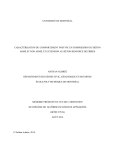
TOSHIBA
STORAGE DEVICE DIVISION
SR-C8002
CD-R/CD-RW DRIVE
PRODUCT SPECIFICATION
MAY 2001
REV. 1.0
Specifications are subject to change without notice
DOCUMENT NUMBER
14708
LIMITATION OF LIABILITY
Those warranties in the express warranty separately agreed between TOSHIBA and your company are the
only warranties given to the consumer and are in lieu of any other warranties, whether express or implied with
regard to this component. TOSHIBA expressly and unequivocally disclaims the warranties of merchantability
and fitness for a particular purpose.
Further, TOSHIBA disclaims all express warranties created by any individual or entity installing this device
into a computer unless such express warranties are made with the prior express written consent of TOSHIBA
or its authorized representatives.
TOSHIBA will not be responsible for any damages, whether compensatory, incidental, consequential, or
special damages of any kind, including but not limited to, punitive or exemplary damages, treble damages,
loss of use or lost profits whether such damages are sought by the end-user or the purchaser herein,
regardless of whether such liability is sought directly or by way of indemnity proceedings in law or equity.
It shall be the responsibility of the purchaser herein to provide the end-user or ultimate consumer with all
product documentation provided with this product including all product specification, manuals, registration
forms and warranty information including product capabilities and limitations. By accepting the component(s),
the purchaser herein below agrees to do so and further accepts the terms of this limitation. The purchaser
herein below expressly waives any and all rights to the contrary.
Warnings:
This equipment (an optical disc drive) handled under the conditions out of equipment specifications
may cause heavy load, heat generation, malfunction, erroneous operation and performance degradation.
Therefore, please handle this equipment properly in compliance with the warnings provided below. In the
event that you do not comply with the warnings, Toshiba cannot guarantee the safety, reliability and
performance of the equipment expressly provided in the specification. Manufacturers and resellers
of the computer system using this equipment and/or this equipment itself shall notify the end-users of
the warnings provided herein and ensure them to comply with these warnings in an appropriate manner.
1. This equipment does not involve any over-current protection circuit. Use an appropriate over-current
protection in the computer system which this equipment would be connected. Toshiba shall not be
liable for any damages to the system which does not have any over-current protection.
2. DO NOT disassemble or modify this equipment. Toshiba shall not make any guarantee to the reliability,
safety and performance of this equipment expressly provided in the specification and nor be liable for
any damages resulting from such unauthorized disassembly or modification.
3. Read carefully and comply with this Product Specification in order to avoid the risk of data error in writing
operation. Such possible data error would be made by any factors other than this equipment (i.e., poor
storage media, misuse of this equipment, malfunction in a computer system connecting this equipment,
etc.). Toshiba shall not be liable for any damages resulting from such data loss. Check whether the
original data is correctly copied or stored upon completion of writing operation.
Take any necessary measures to protect your data such as system backup and/or mirroring disk
subsystems in order to avoid the risk of unexpected data loss or data corruption resulting from failure
in this equipment for some reasons.
Manufacturers and resellers of the computer system using this equipment shall be required to consider
the safety of such computer system and data integrity in order to avoid the risk of any consequential
damages caused by data loss or data corruption and any problems or accident caused by malfunction
of the computer system.
SR-C8002 Rev.1.0
DO NOT use this equipment in the system such as medical equipment which may cause personal injury
or property damages resulting from malfunction of this equipment and unexpected data corruption or
data error in reading operation.
4. Turn off the power for this equipment and wait more than one (1) minute before you eject the disc using
the emergency eject mechanism when a disc cannot be ejected for some reasons in order to avoid the
risk of damages to the disc.
Notice
1. Turn off the system power before mounting/removing this equipment in order to avoid the risk of
damages to this equipment.
2. Insert the DC power plug in correct direction in order to avoid the risk of damages to this equipment.
3. Handle this equipment only in electrostatically safe environment and do not touch connecting terminals
with empty hands when you build in or pull out this equipment from other product in order to avoid the
risk of malfunction of this equipment.
4.DO NOT do any of the following:
4.1. DO NOT use storage media (CD's / DVD's) that are not the correct size or shape, or do not meet the
minimum formatting requirements set forth in section 3.1.(1) of this Product Specification.
4.2. DO NOT insert more than one (1) CD or DVD disc into the drive at any time. Doing so will damage or
destroy this equipment and could damage or destroy the disc or cause data loss or corruption.
4.3. DO NOT load or eject any CD or DVD disc with force. Doing so will damage or destroy this equipment
and could damage or destroy the disc or cause data loss or destruction.
4.4. DO NOT give a strong shock while load or eject operation is in process. Doing so will damage or
destroy this equipment and could damage or destroy the disc or cause data loss or corruption.
4.5. DO NOT eject a CD or DVD disc while the drive is in operation. Doing so will damage or destroy this
equipment and could damage or destroy the disc or cause data loss or corruption.
4.6. DO NOT insert anything else into the drive other than a CD or DVD disc. Doing so will damage or
destroy this equipment.
----- To OEM Customers: ----------------------------------------------------------------Please notify below notice to your customers.
Notice
Copyrighted works including, but not limited to music, video, computer program, database are
protected by copyright laws. Unless specifically permitted under applicable copyright laws,
you cannot copy, modify, assign, transmit or otherwise dispose of any copyrighted work
without the consent of the owner of the copyright.
Please take notice that unauthorized copying, modification, assignment, transmission and
other disposition may be subject to claims for damages and to penalties.
SR-C8002 Rev.1.0
Contents
1. Introduction ---------------------------------------------------------------------------------------------------------------------- 1
2. Features -------------------------------------------------------------------------------------------------------------------------- 1
3. Specifications ------------------------------------------------------------------------------------------------------------------ 2
3.1. Performance ------------------------------------------------------------------------------------------------------------ 2
3.2. Environmental Conditions ---------------------------------------------------------------------------------------- 4
3.2.1. Temperature and Humidity ---------------------------------------------------------------------------------- 4
3.2.2. Dust and Dirt ------------------------------------------------------------------------------------------------------ 4
3.2.3. Vibration ----------------------------------------------------------------------------------------------------------- 5
3.2.4. Atmospheric Pressure and Altitude -------------------------------------------------------------------- 5
3.2.5. Shock --------------------------------------------------------------------------------------------------------------- 5
3.3. Installation Conditions --------------------------------------------------------------------------------------------- 6
3.3.1. Equipment -------------------------------------------------------------------------------------------------------- 6
3.3.2. Installation --------------------------------------------------------------------------------------------------------- 6
3.4. Dimensions and Mass --------------------------------------------------------------------------------------------- 7
3.5. Reliabilities ------------------------------------------------------------------------------------------------------------- 9
3.5.1. Error Rate ---------------------------------------------------------------------------------------------------------- 9
3.5.2. MTBF ---------------------------------------------------------------------------------------------------------------- 9
3.5.3. MTTR ---------------------------------------------------------------------------------------------------------------- 9
3.5.4. Drive Life ----------------------------------------------------------------------------------------------------------- 9
4. Configurations ----------------------------------------------------------------------------------------------------------------- 9
4.1. Electrical Circuits ------------------------------------------------------------------------------------------------------ 9
4.2. Optical Pickup --------------------------------------------------------------------------------------------------------- 9
4.3. Spindle Motor ---------------------------------------------------------------------------------------------------------- 9
4.4. Feed Motor -------------------------------------------------------------------------------------------------------------- 9
5. Functions ------------------------------------------------------------------------------------------------------------------------11
5.1. Disc Data Configurations ------------------------------------------------------------------------------------------11
5.1. 1.CD-ROM Data Configurations ------------------------------------------------------------------------------11
5.1. 2.CD-R/CD-RW Data Configurations -----------------------------------------------------------------------11
5.2. Power ON/OFF Timing --------------------------------------------------------------------------------------------12
6. Interfaces ------------------------------------------------------------------------------------------------------------------------12
6.1. I/O Cable ------------------------------------------------------------------------------------------------------------------12
6.2. Signal Summary -------------------------------------------------------------------------------------------------------13
6.2.1. Signal Specifications ----------------------------------------------------------------------------------------13
6.2.2. Timing of Host Interface (PIO) ----------------------------------------------------------------------------14
6.2.3. Timing of Host Interface (DMA Multi) -------------------------------------------------------------------15
6.3. Connector -------------------------------------------------------------------------------------------------------------16
6.4. Support Command List --------------------------------------------------------------------------------------------17
7. Power Requirements -----------------------------------------------------------------------------------------------------18
7.1. Source Voltage ------------------------------------------------------------------------------------------------------18
7.1.1. Spike --------------------------------------------------------------------------------------------------------------18
7.1.2. Ripple
-----------------------------------------------------------------------------------------------------------18
SR-C8002 Rev.1.0
7.2. Current Drain
-------------------------------------------------------------------------------------------------------18
7.2.1.Sleep
------------------------------------------------------------------------------------------------------------18
7.2.2. Standby ----------------------------------------------------------------------------------------------------------18
7.2.3. Continuous Read -------------------------------------------------------------------------------------------18
7.2.4. Idle ------------------------------------------------------------------------------------------------------------------18
7.2.5. Average ------------------------------------------------------------------------------------------------------------18
7.2.6. Maximum ----------------------------------------------------------------------------------------------------------18
7.2.7. Peak in executing Access ----------------------------------------------------------------------------------18
7.2.8. Write ----------------------------------------------------------------------------------------------------------------18
8. CD Audio
-------------------------------------------------------------------------------------------------------------------19
8.1. Analog Out -----------------------------------------------------------------------------------------------------------19
8.2. Audio Modes -------------------------------------------------------------------------------------------------------19
9. Device Configuration Jumper ----------------------------------------------------------------------------------------19
9.1 Master Mode Setting ----------------------------------------------------------------------------------------------19
9.2 Slave Mode Setting ------------------------------------------------------------------------------------------------19
10.Busy Indicator
-------------------------------------------------------------------------------------------------------------20
11. Emergency Release
--------------------------------------------------------------------------------------------------21
12. Safety Standards/Agency Approvals
13. Electrostatic Discharge
14. Accessories
15. Packaging
---------------------------------------------------------------------------21
----------------------------------------------------------------------------------------------22
--------------------------------------------------------------------------------------------------------------22
-----------------------------------------------------------------------------------------------------------------22
16. CE Declaration of conformity
--------------------------------------------------------------------------------------22
SR-C8002 Rev.1.0
1. Introduction
This document describes TOSHIBA's SR-C8002 CD-R/RW Drive.
2. Features
SR-C8002 reads digital data stored on CD-ROM media and CD-Audio discs.
The CD-ROM media has a 12 cm or 8 cm diameter. It typically contains approximately
600 MBytes or 200 MBytes of information respectively. (1 MByte=220 Bytes)
This drive reads CD-ROM media at maximum 24 times faster rotational speed.
This drive is a new generation drive with highest performance such as 120 ms access Time.
This drive writes CD-R/RW media at maximum 8 time faster rotational speed.
This drive shows highest performance such as 60,000 hour MTBF.
This drive offer long life and high durability because the disc is read by a LASER, thereby eliminating physical
contact with the disc.
This drive support ATAPI (ATA Packet interface) Revision 2.6 spec. and SFF8090 Version 3
(Mt. Fuji Commands for CD Devices) of CD Command.
1/24
SR-C8002 Rev.1.0
3. Specifications
3.1.Performance
(1) Applicable Write Format CD-R/RW:
Disc at once, Track at once, Session at once, Packet write
(2) Applicable Write Disc *1 CD-R/RW:
CD-DA, CD+(E)G, CD-MIDI, CD-ROM,CD-ROM XA,
MIXED MODE CD, CD-I, CD-I Bridge (Photo-CD, Video-CD)
Multisession CD (Photo-CD, CD-EXTRA, Portfolio)
(3) Applicable Read Disc *2
CD :
CD-DA, CD+(E)G, CD-MIDI, CD-TEXT, CD-ROM, ,
CD-ROM XA, MIXED MODE CD, CD-I,
CD-I Bridge (Photo-CD, Video-CD)
Multisession CD (Photo-CD, CD-EXTRA, Portfolio, CD-R,
CD-RW), CD-R, CD-RW
(4) Data Capacity
User Data/Block
Data Cpacity/Disc
(5) Rotational Speed
Read: ROM Data Media
CD-DA, Video-CD
CD-RW
Hight Speed CD-RW
Write: CD-R, High speed CD-RW
CD-RW
Mode-1: 2,048 Byte/Block
Mode-2: 2,336 Byte/Block
Mode-1: 656.5 MB (688.4 Million Byte) * 3
Mode-2: 748.8 MB (785.2 Million Byte) * 3
(1 GB=230 Byte, 1 MB=2 20 Byte, 1 KB=210 Byte)
: Approx. 5,100 rpm (10.3-24X CAV)
: Approx. 1,290-2,000 rpm (4-6X PCAV)
: Approx. 1,290-2,000 rpm (4-6X PCAV)
: Approx. 2,570-4,000 rpm (8-12X PCAV)
: Approx. 1,700-3,960 rpm (8X CLV)
: Approx. 850-1.980 rpm (4X CLV)
2/24
SR-C8002 Rev.1.0
(6) Transfer Rate
Sustained Block Transfer Rate
776-1,800 Block/s (10.3-24X CAV)
300-450 Block/s (4-6X PCAV)
Sustained Data Transfer Rate
Mode-1:
Mode-2:
10.3X-24X CAV 1,552-3,600 KByte/s
4X-6X PCAV 600-900 KByte/s
10.3X-24X CAV 1,769-4,104 KByte/s
4X-6X PACV 684.4-1,026.6 KByte/s
Burst Data transfer Rate
16.7 MByte/s (PIO Mode 4 )
16.7 MByte/s ( Multi word DMA transfer mode-2)
( 1 KByte=2 10 Byte=1,024 Bytes, 1 MByte=220 Byte=1,048,576 Bytes)
(7) Access Time
Average Random Access Time*4
Average Random Seek Time*5
Average Full Stroke Access Time*6
120 ms Typ (10.3-24X)
105 ms Typ (10.3-24X)
170 ms Typ (10.3-24X)
(8) Spin up Time ( Focus Search Time and Disc Motor Start up Time )
2.0 s Typ (10.3-24X)
(9) Data Buffer Capacity
2 MByte
*1: This drive write the data on the disc of CD-R, CD-RW format. However, in order to run applications that
use these formats you must first have the required software and/or hardware.
*2: All disc written in CD formats, except CD-DA (audio), require additional specific
application software and/or hardware. This drive referred in the specification is capable of reading
these data formats. However, in order to run applications that use these formats you must first have the
required software and/or hardware.
*3: Data capacity when recording depends on the condition of the record and decreases from this
occasionally.
*4: Measured by performing multiple accesses which means reads of data blocks over whole area of the
media from 00 min 02 sec 00 Frame to 60 min 01 sec 74 Frame (552.96 Million Byte:87 %
of total area at linear velocity of 1.3 m/s) more than 3000 times. Includes positioning, setting, latency
time and ECC implementation time (if required).
*5: Measured by performing multiple seek which means seeks of data block over whole area of the media
from 00 min 02 sec 00 Frame to 60 min 01 sec 74 Frame more than 3000 times. Includes positioning,
setting time which is same definition as HDD.
*6: Measured by performing maximum accesses which means reads of each data block of 00 min
02 sec 00 Frame and 60 min 01 sec 74 Frame alternately more than 100 times.
Includes positioning, setting, latency time and ECC implementation time (if required)
3/24
SR-C8002 Rev.1.0
(10) Drawer Load/Release Load:
Release:
Manual
(a) Electrical Release (Release Button)
(11) Air Flow
(b) Release by ATAPI command
(c) Emergency Release
Not Required
(12) Acoustic Noise
40 dB (IEC 179 A weighted at 1 m)
(13) Power Supply
+5 V (details in Section 7)
3.2. Environmental Conditions
This drive should be used under the conditions listed below.
3.2.1.Temperature and Humidity
(1) Operating Temperature
5 °C to 50 °C *1
(2) Storage Temperature
-10 °C to 60 °C
(3) Shipping Temperature
-40 °C to 65 °C *2
(4) Operating Temperature Gradient
11 °C/hour (max)
(5) Storage Temperature Gradient
20 °C/hour (max)
(6) Shipping Temperature Gradient
20 °C/hour (max) *2
(7) Operating Humidity
8 % to 80 %
(8) Storage Humidity
5 % to 95 %
(9) Shipping Humidity
5 % to 95 % *2
(10) Wet bulb Maximum Temperature
27 °C
(11) Condensation
In all the above conditions there must be no condensation
*1: Except for disc
*2: Packed in Toshiba original shipping package.
3.2.2.Dust and Dirt
unspecified
4/24
SR-C8002 Rev.1.0
3.2.3.Vibration
(1) Operating (CD 10.3-24X Read) (1 Oct/min) ---------------- no hard error ----5 to 500 Hz 2.45 m/s2 [0.25 G] (0-p)
(excluding resonance point)
(2) Operating (Write) (1 Oct/min) ---------------- no hard error ----5 to 500 Hz 2.45 m/s2 [0.25 G] (0-p)
(excluding resonance point)
(3) Non-operating (1 Oct/min) --------- no damage ----5 to 10 Hz 5 mm (p-p)
10 to 500 Hz 9.8 m/s2 [1 G] (0-p)
(4) Shipping (Packaged) (1 Oct/min) -----
3.2.4.Atmospheric Pressure and Altitude
(1) Operating
(2) Shipping
3.2.5.Shock
(1) Operating (Read )
--------------------
------------------------
(2) Operating (Write) ------------------------
no damage ----10 to 25 Hz 9.8 m/s2 [1G] (0-p)
X Y Z/30 min each
0 to 3,000 m
0 to 12,000 m
no hard error --------------14.7 m/s 2 [1.5 G] (Horizontal)
(Half sine wave 11 ms/10 s interval)
no data loss -------------98 m/s2 [10 G]
(Half sine wave 11 ms/10 s interval)
no error -------------14.7 m/s 2 [1.5 G] (Horizontal)
7.8 m/s2 [0.8 G] (Vertical)
(Half sine wave 11 ms/10 s interval)
(3) Non-operating (with no Disc mounted) ----- no damage ----490 m/s 2 [50 G] (Half sine wave 11 ms)
980 m/s 2 [100 G] (Half sine wave 3 ms)
(4) Drop (Packaged) ------------------(a) Bulk Package (50 pcs)
(b) Bulk Package (20 pcs)
no damage ----1 drop at 0.4 m (Bottom side only)
0.6 m drops once for each 6-surface, 1-edge and 1-corner
5/24
SR-C8002 Rev.1.0
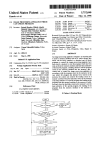
3.3. Installation Conditions
30 °
15 °
15 °
15 °
15 °
15 °
15 °
15 °
15 °
15 °
Figure 1 Mounting angle
3.3.1. Equipment
(1) When mounting the equipment, use four M2-P0.4 tapping holes located on the left and right
sides of the equipment.
(2) The opposite surface of the bearing surface (fitting surface when mounting) of the tapping
holes must be kept flat so that the bearing surface can be fit evenly.
(3) Use the mounting screws which do not enter deeply inside the equipment more than
specified value.
(4) When mounting the equipment, the tightening torque of four screws must be even.
The recommended screw tightening torque is 0.2 Nm.
3.3.2.Installation
(1) The mounting surface of the equipment must keep good flatness.
When mounting, care should be paid that an excessive force which may caused torsional
distortion on the equipment does not apply to the equipment. The recommended surface
flatness for the mounting surface should be less than 0.2 mm.
(2) Install the equipment with enough space as much as possible in all directions around the
equipment. Care should be paid that the equipment does not touch with peripheral
instruments even if vibration, mechanical shock, etc. are applied to the equipment.
For the maximum dimension of the equipment thickness (12.9 mm), it is recommended that a
clearance more than 0.5 mm should be left the thickness direction.
For the clearance around the front bezel, it is recommended that the clearance more than
0.8 mm should be left in all directions.
(3) Care should be especially paid for the heat effect. Keep the air ventilation and isolate from
heat of the environmental condition. Then, install the equipment where the
environmental temperature at the bottom center of cabinet does not exceed 50 °C.
6/24
SR-C8002 Rev.1.0
(4) Do not add the force beyond the indicated force on the top and bottom cover of the
equipment. (The restricted force range for the top cover is shown in the Figure 2.)
(For the bottom cover, the applied force should be less than 2N on whole area.)
2N
129
1N
R63
0.5 N
R59
37
R46
24
Do not add
the force
5.4
128
64
70
74
7
11
20
Figure 2 Restricted force range applied for the top cover
(5) The characteristics of EMC (Electro Magnetic Compatibility) are primarily influenced by the
mounting method of this equipment. Attach this equipment by considering an appropriate
method and structure.
3.4. Dimension and Mass
----- See Figure 3 for details -----
(1) External Dimensions (W x H x D)
128 mm x 12.7 mm x 126.1 mm (excluding bezel)
(2) Mass
0.24 kg (Net)
13.9 kg (Bulk Packaged 50 pcs)
5.7 kg (Bulk Packaged 20 pcs)
7/24
SR-C8002 Rev.1.0
( Unit: mm )
Figure 3
External Dimensions
8/24
SR-C8002 Rev.1.0
3.5. Reliabilites
3.5.1. Error Rate
(1) Hard Read Error Rate (Byte Error Rate) ----- Allowing 5 Retries(default) ----Mode 1:10-15 Max
Mode 2:10-12 Max
(2) Seek Error Rate --- Allowing 10 Retries
(default)
10 -6 Max
3.5.2. MTBF
Assumptions: Power On Hours
On/Off Cycles
Number of Access
Operating Duty Cycle (Read)
Operating Duty Cycle (Write)
60,000 h
5,436 h/year
313 cycles/year
600,000 accesses/year
20 % of Power On Time (Reading/Seeking)
2 % of Power On Time (Writing/Seeking)
3.5.3. MTTR
0.5 h
3.5.4. Drive Life
(1) Drawer Load/Release
(2) Interface connector Attach/Detach
15,000 h or 5 years (earlier one)
10,000 times or more
500 times or more
4. Configuration
See Figure 4 for details of the configurations
4.1. Electrical Circuits
(1) Drawer Release Switch and Release Detection Switch
(2) Optical Pickup Servo Drive Circuit
(3) Feed Motor Drive Circuit
(4) Laser Diode Control Circuit
(5) EFM Demodulator, Error Correction Circuit and DA converter
(6) IDE/ATAPI Control and CD-ROM Error Correction Circuit
(7) CIRC Encoder
(8) EFM Encoder
(9) ATIP Demodulator
(10) Disc Moter Control Circuit
4.2. Optical Pickup
Semiconductor Laser
4.3. Spindle Motor
Brushless DC Motor
4.4. Feed Motor
DC Motor
9/24
SR-C8002 Rev.1.0
10/24
LED
Drawer
Release
Detector
Release
Switch
Release Solenoid
Position
Detector
PUH
GPIO
63F49
TPIC1318
Power Driver
Power Driver
Power Driver
Power Driver
BH6526FV
Focus Amp
Command Dec.
RAM
Int.
Control
Timer
FLASH ROM
Micro
Processor
CD-BUS Interface
FV
Converter
33.86 MHz
Comparator
Feed Motor
Disc Motor
RF Amp EQL
Tracking Amp
TA1323F
Commad DCC
Converter
Disc EQL
D/A
Digital
Audio
Decoder
Audio
D/A
D-RAM Interface
DRAM (16M)
22.58 MHz
Clock
ATIP Decoder
CLV Controller
Write Strategy
CD Encoder
Digital Audio Encoder
ATIP Demodulator
Error Correct
Header detect
EDC
Memory Controller
ECC
IDE / ATAPI Interface
Sync/ID Detect
RC5E839
DRAM (1M)
D-RAM Interface
Servo
Controller
Clock
Feed EQL
D/A
FG
Focus EQL
D/A
D/A Track EQL
A/D
De-Scramble
Demodulator
Focus Amp
Laser Control
Data Slicer PLL
TC94A03
Tracking Amp
ATIP Filter
AK8570A
CD-R / RW DRIVE MODEL SR-C8002 BLOCK DIAGRAM
BUS Control
Clock
Figure 4 Configuration
SR-C8002 Rev.1.0
Regulator
+5V
Muting
MM3067
5.Functions
5.1. Disc Data Configurations
5.1.1. CD-ROM Data Configurations
Figure 5 shows how the data is structured in program units
1 block=1/75 s
TNO
Time
0
TOC
1-Disc
SYNC
12 bytes
Lead-in
Min
Sec
Block 2
approx.
~
AA
~
300 k-Blocks
~
~
Mode
~
Block
2
Blocks(0~74)
User Data
2048 bytes in Mode-1
2336 bytes in Mode-2
Min
Sec
4 bytes
Header
Block 1
Block
1
Minutes
Second(0~59)
~
ECC (Mode-1)
288 bytes
~
~
Lead out
Figure 5 CD-ROM Disc Data Configuration
5.1.2. CD-R / CD-RW Data Configurations
Before writing
CD-R / CD-RW disc contains time-code information called ATIP.
ATIP is abbreviation of "Absolute Time In Pre-groove" in the wobbling groove by modulating
the carrier frequency.
(Address information is pre-formatted to ATIP on the CD-R / CD-RW disc and method for the
guide groove to wobble by FM modulation.)
Figure 6 shows the composition of ATIP.
(n-1)
Synchronization (4 bit)
Address
Min
(8 bit)
Sec
(8 bit)
Frame
(8 bit)
CRC
(14 bit)
n
Address
n+1
Address
n+2
Address
Figure 6 CD-R / CD-RW Disc ATIP Data Configuration
After Writing
Data are written in CD format synchronizing with ATIP.
11/24
SR-C8002 Rev.1.0
5.2. Power ON/OFF Timing
Figure 7 shows the initialization sequence
Power ON or
ATAPI-RST
Max. 550 ms
"Command" Receivable
System
Initialization
Max 2 s
Focus Search
Max 3.5 s
Spindle ON
Learning
Max 30s, Typ 12 s
(Single Session Disc)
"Read-Command"
Stand-by
Acceptable
"TEST UNIT
READY"
Command
"Check Condition" Status
"Good" Status
Figure 7 Initialization Sequence
6. Interface
(1) The interface is based on T13/1321D (AT Attachment with Packet Interface-5, ATA/ATAPI-5) Revsion 3
(Feb. 29, 2000), SFF-8020i (Small Form Factor Committee Specification of ATA-Packet Interface for
CD-ROMs) Revision2.6 (Nov. 27, 1995), SFF-8090 Ver.3, Rev.1.00 ('99-2-10).
(2) 58 (ATAPI, ATA) commands are usable.
(3) The 2 MByte data buffer handles both high speed and low speed data transmission.
(4) The largest block size on playback is 2,647 Bytes.
The data length for each block is changeable by command.
6.1. I/O cable
Table1 shows the cable parameters.
Min
Cable length
Max
0.46 m
Driver IoL sink current for 5 V operation
Driver IoL sink current for 3.5 V operation
12 mA
8 mA
Driver IoH sink current
-400 µA
Driver capacitive loading
25 pF
Table 1 Cable parameters
12/24
SR-C8002 Rev.1.0
6.2.Signal summary
The physical interface consists of single ended TTL compatible receivers and drivers
communicating through a 50P-connector as shown in Figure 11 and Figure 12 "Interface connector".
6.2.1. Signal Specification
Figure 8 shows the Signal Specifications
Receivers/Drivers Caracteristics withoutExternal pullup Resistor
Type
Sig. Name
Min
VOH Voltage Output High
Rx
HD0 - HD15
VOL Voltage Output Low
VIH Input HIGH Voltage
Rs1 Rs2
/DASP
P
/PDIAG
N
timing
control
Rx
/IOCS16
VIL
ILI
IOL
Input LOW Voltage
Input leakage Current
ILO
Driver sink current
Output Leakage Current
CI
Input Capacitance
CO
Output Capacitance
Bidirectional
Rx=infinity
Rs1=0 OHM
IOL=12
mA
0.4 V
Rs2=33 OHM
2.4 V
TTL
HD0-HD15
0.6 V
TTL
Rx=10 kOHM
-30 µA -400 µA Pullup Resistor(Ri)
Rs1=0 OHM
24 mA
Rs2=0 OHM
-30 µA -400 µA Pullup Resistor(Ri)
/PDIAG,
15 pF
/DASP
15 pF
Rs
Driver sink current
CO
Output Capacitance
IOH=1 mA
Vdd-0.4 V
0.5 V
VOL Voltage Output Low
IOL
Max
NOTE
Condition
IOL=12 mA
Open Drain
24 mA
Rx=1.2 kOHM
Rs=0 OHM
15 pF
N
VOH Voltage Output High
Rx
P
Rs
IORDY
N
VOL Voltage Output Low
timing
control
IOL
Driver sink current
CO
Output Capacitance
VOH Voltage Output High
/HDRQ
/INTRQ
/HWR
/HRD
HA0 - HA2
/HCS1/HCS3
/HDAK
RESET
P
Rs
N
Rx
Rs
100 kOHM
82 OHM
timing
control
IOH=400 µA
2.4 V
0.5 V
Rx=1 kOHM
Rs=22 OHM
IOL=12 mA
24 mA
15 pF
IOH=400 µA
Vdd-0.4 V
Rs=22 OHM
VOL
Voltage Output Low
IOL
Driver sink current
CO
Output Capacitance
VIH
Input HIGH Voltage
2.0 V
VIL
Input LOW Voltage
ILI
Input leakage Current
0.8 V TTL
-30 µA -400 µA Pullup Resistor(Ri)
CI
Input Capacitance
VIH
Input HIGH Voltage
VIL
Input LOW Voltage
ILI
Input leakage Current
CI
Input Capacitance
0.4 V
IOL=12 mA
/INTRQ
/HDRQ
24 mA
15 pF
TTL
15 pF
Rx=infinity
Rs=82 OHM
/HWR, /HA0-2,
/HDAK
Rx=infinity
Rs=120 OHM
/HRD
Rx=10 kOHM
Rs=82 OHM
/HCS1,/HCS3
2. 4 V
0.6 V
-30 µA -400 µA Pullup Resistor(Ri)
15 pF
Figure 8 Signal Specifications
13/24
SR-C8002 Rev.1.0
6.2.2.Timing of Host Interface (PIO)
Figure 9 shows the Host Interface Timings
t0
Address valid*1
t2
t1
t9
DIOR-/DIOW-*1
t2i
Write data valid*1
t3
Read data valid*1
t4
t5
t6Z
t7
t6
IOCS16-*1
tA
IORDY
tB
t8
tRD
*1: In all timing diagrams, the low line indicator negated, and the upper line
indicators asserted.
PIO timing parameters min (ns) max (ns)
Min Time (ns)
Max Time (ns)
t0
Cycle time
120
t1
Address valid to DIOR/DIOW-setup
25
t2
DIOR/DIOW-pulse wide
70
t2i
DIOR/DIOW-recovery time
25
t3
DIOW-data setup
20
t4
DIOW-data hold
10
t5
DIOR-data setup
20
t6
DIOR-data hold
t6Z
DIOR-data tristate
30
t7
Addr valid to IOCS 16-assertion
30
t8
Addr valid to IOCS 16-negation
30
t9
DIOR/DIOW-to address valid hold
tRD
Read Data Valid to IORDY active
tA
IORDY setup
tB
IORDY pulse wide
5
10
0
35
1250
Figure 9 Host Interface Timing (PIO Mode4)
14/24
SR-C8002 Rev.1.0
6.2.3.Timing of Host Interface (DMA Multi)
Figure 10 shows the Host Interface DMA multi word Timings
t0
DMARQ
tL
DMACK-*1
tK
tD
tI
tJ
DIOR-/DIOW-*1
tZ
tE
Read
DD0-15
tF
Write
DD0-15
tG
tH
*1: In all timing diagrams, the low line indicator negated, and the upper line
indicators asserted.
Multi word DMA
timing parameters min(ns) max(ns)
Min time
(ns)
Max time
t0
Cycle time
tC
DMACK to DMREQ delay
tD
DIOR-/DIOW-16-bit
tE
DIOR- data access
tF
DIOR- data hold
tZ
DMACK- to tristate
tG
DIOR/DIOW- data setup
20
tH
DIOW- data hold
10
tI
DMACK to DIOR-/DIOW- setup
0
tJ
DIOR-/DIOW- to DMACK hold
5
tKr
DIOR- negated pulse width
25
tKw
DIOW- negated pulse width
25
tLr
DIOR- to DMREQ delay
35
tLw
DIOR- to DMREQ delay
35
(ns)
120
--70
--5
25
Figure 10 Host Interface Timing (Multi Word DMA Mode 2)
15/24
SR-C8002 Rev.1.0
6.3. Connector
Figure 11 shows the connector and Figure 12 shows the interface pin assignments
Use Japan Aviation Electronics Industry Limited KX15-50KLD L or equivalent.
Conformable connector is Japan Aviation Electronics Industry Limited KX14-50 series.
TOP
DVD-ROM DRIVE REAR VIEW
8
6
4
5
10
2
7
12
1
9
3
11
16
14
18
13
17
22
20
15
19
24
21
23
30
28
32
26
29
25
31
36
34
27
33
38
35
37
42
40
44
39
43
48
46
41
45
50
47
49
BOTTOM
Figure 11 Connector pin assignments
Signal
name
Audio L-CH
Audio Ground
/RESET
DD7
DD6
DD5
DD4
DD3
DD2
DD1
DD0
Ground
/DIOW :STOP
IORDY: /DDMARDY: DSTROBE
INTRQ
DA1
DA0
/CS1FX
/DASP
+5 V(Motor)
+5 V(Logic)
Ground
Ground
CSEL
Vender unique*
I/O
O
I
I/O
I/O
I/O
I/O
I/O
I/O
I/O
I/O
I
O
O
I
I
I
I/O
I
I
I
I
Connector
contact
1
3
5
7
9
11
13
15
17
19
21
23
25
27
29
31
33
35
37
39
41
43
45
47
49
I/O
2
4
6
8
10
12
14
16
18
20
22
24
26
28
30
32
34
36
38
40
42
44
46
48
50
O
I/O
I/O
I/O
I/O
I/O
I/O
I/O
I/O
O
I
I
O
I/O
I
I
I
I
I
I
Signal
name
Audio R-CH
Ground
DD8
DD9
DD10
DD11
DD12
DD13
DD14
DD15
DMARQ
/DIOR: /HDMARDT: HSTROBE
Ground
/DMACK
/IOCS16
/PDIAG
DA2
/CS3FX
+5 V(Motor)
+5 V(Motor)
+5 V(Logic)
Ground
Ground
Ground
Vender unique*
A slash character(/) at the beginning of a signal name indicates it is asserted at the low level
(active low).
*Vender unique: Don't Connect (50 PIN)
*Vender unique: 49 PIN
Figure 12 Signal assignments
16/24
SR-C8002 Rev.1.0
6.4. Support Command List
ATAPI Packet Command
No
1
2
3
4
5
6
7
8
9
10
11
12
13
14
15
16
17
18
19
20
21
22
23
24
25
26
27
28
29
30
31
32
33
34
35
36
37
38
39
40
41
42
43
44
OP Code
00h
01h
03h
04h
12h
1Bh
1Ch
1Dh
1Eh
23h
25h
28h
2Ah
2Bh
35h
42h
43h
44h
45h
46h
47h
4Ah
4Bh
4Eh
51h
52h
53h
Command Description
Test Unit Ready
Rezero Unit
Request Sense
Format Unit
Inquiry
Start / Stop Unit
Receive Diagnostics
Send Diagnostic
Prevent / Allow Medium Removal
Read Format Capacities
Read Capacity
Read (10)
Write (10)
Seek (10)
Synchronize Cache
Read Sub-Channel
Read TOC / PMA / ATIP
Read Header
Play Audio (10)
Get Configuration
Play Audio MSF
Get Event Status Notification
Pause / Resume
Stop Play / Scan
Read Disc Information
Read Track / RZone Information
Reserve Track
55h
5Ah
5Bh
5Ch
5Dh
A1h
A2h
A5h
A7h
A8h
ACh
B6h
B9h
BAh
BBh
BDh
BEh
Mode Select (10)
Mode Sense (10)
Close Track / Session
Read Buffer Capacity
Send Cue Sheet
Blank
Send Event
Play Audio (12)
Set Read Ahead
Read (12)
Get Performance
Set Streaming
Read CD MSF
SCAN
Set CD Speed
Mechanism Status
Read CD
17/24
SR-C8002 Rev.1.0
ATA Command for ATAPI
No.
OP Code
Command Description
-
00h
Nop
1
2
08h
ATAPI Soft Reset
20/21h
Read Sector (s)
3
4
5
6
7
8
9
10
11
12
13
14
90h
Execute Drive Diagnostics
A0h
ATAPI Packet Command
A1h
ATAPI Identify Device
E0h
Standby Immediate
E1h
Idle Immediate
E2h
Standby
E3h
Idle
E5h
Check Power Mode
E6h
Sleep
E7h
Flush Cache
ECh
ATA Identify Device
EFh
Set Feature
7. Power Requirements
7.1. Source Voltage
+5 V +/-5 % (Operating)
+5 V +/-8 % (Start up)
7.1.1. Spike
100 mV
(p-p)
Max.
7.1.2. Ripple
100 mV
(p-p)
Max.
7.2. Current Drain (Typical value)
7.2.1.Sleep
+5 V
40 mA
7.2.2.Standby (Laser off, Motor off)
70 mA
7.2.3. Continuous Read (Data/Audio)
620 mA (4-6X)
900 mA (10.3-24X)
7.2.4.Idle (Laser on, Motor on)
600 mA (10.3-24X)
7.2.5. Average (20% Random Access)
900 mA (10.3-24X)
7.2.6. Maximum (100% Random Access)
950 mA (10.3-24X)
7.2.7. Peak in executing Access
(Exclude Spike Current)
*Spike: Less than 1 ms of duration
1,650 mA
7.2.8. Write
760 mA (CD-R/RW)
820 mA (High Speed CD-RW)
18/24
SR-C8002 Rev.1.0
8.CD Audio (Test condition: Ordinary temperature)
8.1. Analog Out --- in case of the attenuator is set at 0 dB by the command --(1) Output Level
0.8 V (rms)+/-1 dB
(2) Type
Unbalanced
(3) Load Impedance
47 kOHM min
(4) Frequency Response
20 Hz to 20 kHz+/-3.0 dB. (at 47 kOHM Load)
(5) Distortion
0.04 % Max. (at 1 kHz w/20 kHz LPF)
(6) Signal to Noise Ratio
80dB Typ (IEC179 A-Weighted)
8.2. Audio Modes
(1) 16 Modes including 'Stereo', 'Lch Mono', 'Rch Mono' and 'Mute' are selectable by command.
Default mode is 'Stereo'.
(2) 16 Steps of attenuation level for the Audio Output is selectable by command.
Default level is 0 dB.
9. Device Configuration Jumper
9.1. Master Mode Setting
Short-circuit the PIN 47 and PIN 48 of I/O connectors.
9.2.Slave Mode Setting
Open the PIN 47 of I/O connectors.
(Optional)
9.1. Master Mode Setting
Open the PIN 47 of I/O connectors.
9.2. Slave Mode Setting
Short-circuit the PIN 47 and PIN 48 of I/O connectors.
19/24
SR-C8002 Rev.1.0
10. Busy Indicator
The LED at Front Bezel (Busy Indicator) indicates the drive status.
Color: AMBER
(1) After Drawer is closed, Busy Indicator start blinking at 0.8 s intervals, and then ----(1-1) Turns off when the drive in the 'Idle' status.
0.8 s
Light Off
Figure 13 Idle
(1-2) Continuously off when no disc is mounted.
0.8 s
Light Off
Figure 14 No disc
(1-4) Continuously on when media has problem
0.8 s
Light On
Figure 15 Media Problem
(2) When playing an audio track, Busy Indicator is blinking at 1.6 s intervals.
1.6 s
Figurer 16 CD-Audio playback
(3) When performing 'Data Access' and during 'Data Transfer' and 'write' Busy Indicator keeps turn On.
Light On
Figurer 17 Data Access and Data Transfer
(4) When pushing Release button, Busy indicator is blinking at 0.4 s intervals.
0.4 s
Light Off
at the Release
Figurer 18 Release
20/24
SR-C8002 Rev.1.0
11.Emergency Release
Execute following procedure only in the case of emergency (Drawer will not release and disc
can not be removed although pressing Release Button).
(1) Turn the drive supplying power off.
(2) Insert solid bar (like paper clip) into Emergency Release hole and push as shown in Fig.19.
Then Drawer will be released.
(3) After removed the disc, gently push Drawer to close.
15 mm
diameter 1.0 mm
Figurer 19 Emergency Release
12.Safety Standards/Agency Approvals (TENTATIVE)
(1) Safety
EN60950
UL 1950
CAN/CSA-22.2 No.950
(2) Laser
FDA 21CFR (U.S.A./DHHS)
EN60825-1 (Europe)
(3) EMC
CE
EN55022
: 1998 [Radio disturbance characteristics-IT
equipment Class B (including domestic
environment
EN55024 (EMS)
: 1998 [Information Technology equipmentImmunity characteristices Limits and
methods of masurement]
IEC61000-4-2+A1 : 1995+1998 [CD:4 kV, ID: 4 kV, AD:8 kV]
IEC61000-4-3
: 1996 [3 V/m, 80-1000 MHz, 1 kHz 80 % AM ]
IEC61000-4-4
: 1995 [AC-line: 1 kV, I/F 0.5 kV
f: 5 kHz, Polarity: +/-]
IEC61000-4-5
: 1995 [AC-line: 2 kV/1 kV, Polarity: +/-]
IEC61000-4-6
: 1996 [3 V, 0.15-80 MHz, 80 % AM]
IEC61000-4-8
: 1993 [1 A/m, 50 Hz]
IEC61000-4-11
: 1994 [>95 % 0.5, 30% 25, >95 250]
KOREAN EMC No. 13237
TAIWAN EMI
CNS 13438
21/24
SR-C8002 Rev.1.0
13. Electrostatic Discharge
Standard
IEC61000-4-2
(1) Operating
8 kV or less
(2) Damage including
15 kV or more
14. Accessories
None
15. Packaging
(1) 50 units in a bulk package
24 bulk packs on one pallet.
* All transportation is allowed with pallet.
(Transportation with bulk package is not allowed.)
(2) 20 units in a bulk package
24 bulk packs on one pallet.
(Transportation with bulk package is allowed.)
(3) 1 unit in a bulk package
(Transporttation with bulk package is allowed.)
16. CE Declaration of conformity
Please refer to attached Annex 1.
22/24
SR-C8002 Rev.1.0
TOSHIBA
TOSHIBA EUROPE GMBH
EU-Declaration of Conformity
Product:
CD-R/RW Drive
Manufacturer(s):
Toshiba Corporation
1-1, Shibaura 1-chome, Minato-ku, Tokyo 105-8001 Japan
See page 2 for other locations
Model:
SR-C8002
Options:
None
Toshiba declares that the above mentioned product(s) with or without
the listed options comply to the EU-Directives and standards as listed on page 2.
Last two digits of the year in which the CE mark affixed : 01
Responsible for CE-marking:
Toshiba Europe GmbH
Signed by:
Mr. K.Hachisu, President of Toshiba Europe GmbH
Place:
D-41460 Neuss
Date:
April 19, 2001
Signature:
----------------------------------------------------------
This declaration certifies compliance with the listed directives, but does not constitute an
assurance of characteristics.
The safety information in the supplied product documentation must be observed.
...........................................................................................................................................................
Document No.:
YEA-R2597
Page:
1 of 2
............................................................................................................................................................
[History if issue]
Issued
: Apr. 12, 2001
...................................................
Revision A
:
Ref.:
...................................................
.........................
Revision B
:
Ref.:
...................................................
.........................
Revision C
:
Ref.:
...................................................
.........................
Revision D
:
Ref.:
...................................................
.........................
TOSHIBA EUPOPE GMBH
HAMMFELODAMMB.D-41460NEUSS
GESCHAFTSUHRER
POSTFCH 101482. D-41414 NEUSS
HISATSUGU NONAKA
TELEFON: (02131) 158-01
HRB 3479 AMTSGERICHT NESS
TELFAX : (02131) 158-341
Annex 1
23/24
SR-C8002 Rev.1.0
24/24
SR-C8002 Rev.1.0
SR-C8002
CD-R/RW Drive
Address
X
Related EU-Directive
89/336/EEC
Radio disturbance characteristics-IT equipment
Class B (including domestic environment)
Information Technology equipment-Immunity
characteristices Limits and methods of masurement
CD: 4 kV, ID: 4 kV, AD: 8 kV
3 V/m, 80-1000 MHz, 1 kHz 80 % AM
AC-line: 1 kV, I/F 0.5 kV f: 5 kHz, Polarity: +/AC-line: 2 kV/1 kV, Polarity: +/3 V, 0.15-80 MHz, 80 % AM
1 A/m, 50 Hz
>95 % 0.5, 30% 25, >95 250
Level/Test condition
YEA-R2597
2 of 2
Page:
Revision:
19 Minase, Fukihata Goshogawara-shi, Aomori 037-0003 Japan
3-31-2779, Minami-cho, Misawa-shi, Aomori-ken 033-0036 Japan
4-5 Shoubu, Ubayachi Goshogawara-shi, Aomori 037-0015 Japan
207 Aza Koamon, Rokugo, Rokugo-machi, Senboku-gun, Akita 019-1404 Japan
257 Nakano Yuzawa-shi, Akita 012-0041 Japan
81-87 Iwai, Aiuchi, Shiura-machi, Kitatsugaru-gun, Aomori, 037-0401 Japan
13-10, Matsumoto, Tsuji, Itayanagi, Kita-Tyugaru-gun, Aomori, 038-3645 Japan
103 East Main Avenue Extension, Special Export Processing Zone,
Laguna Technopark, Binan, Laguna Philippines
North Science Avenue Laguna Techno Park Inc. Binan, Laguna Philippines
1-2 Aza-Miyazaki, Kizukuri-machi, Nishi-Tugaru-gun Aomori 038-3157 Japan
24-1 Aza Azumazawa, Ohaza Fukaura, Fukaura-machi, Nishi-Tsugaru-gun, Aomori, 037-0401 Japan
Document No.:
Integrated Microelectronic Inc.
EMS Kizukuri Corp.
EMS Fukaura Co., Ltd
Toshiba Multi Media Devices Co, Ltd
Toshiba Misawa Media Devices Co, Ltd
EMS Corp.
Hokuto Communication Industrial Co., Ltd.
Yuzawa Denshi Kogyo Co., Ltd.
Tsugaru Technica Co., Ltd.
Emusu Itayanagi Co., Ltd.
Toshiba Information Equipment (Philippines) Inc
Manufactuer(s) Location
Model
1995 +1998
1996
1995
1995
1996
1993
1994
IEC61000-4-2+A1
IEC61000-4-3
IEC61000-4-4
IEC61000-4-5
IEC61000-4-6
IEC61000-4-8
IEC61000-4-11
EMC-immunity
Product/Options
1998
EN55024
EMC-emission:
899/336/EEC
(EMC Directive)
1998
EN55022
Related Standard
ED-Directive
Issude
EU-Declaration of Conformity
Deviation List
Page Item
1
2. Features
2
3
Rev # 0.5
This drive is a new generation.....
.....such as 95 ms access Time.
Rev # 1.0
This drive is a new generation.....
.....such as 120 ms access Time.
CD-RW
Approx. 5,100 rpm (10.3-24X CLV)
Approx. 1,200-2,000 rpm
(4-5.7X PCAV)
TBD (Target Max 10X PCAV)
Hight Speed CD-RW
-----
Approx. 5,100 rpm (10.3-24X CAV)
Approx. 1,290-2,000 rpm
(4-6X PCAV)
Approx. 1,290-2,000 rpm
(4-6X PCAV)
Approx. 2,570-4,000 rpm
(8-12X PCAV)
3.1.Performance
(5) Rotational Speed
Read: ROM Data Media
CD-DA, Video-CD
Write: CD-R, CD-RW
Write: CD-R, CD-RW
: Approx. 850-1.980 rpm
(4X CLV)
Write: CD-R, CD-RW
: TBD (2X CLV)
Write: CD-R, High spped CD-RW
CD-RW: Approx. 850-1.980 rpm
(4X CLV)
(Add CD-RW)
Delete the : TBD (2X CLV)
300-428 Block/s (4-5.7X PCAV)
300-450 Block/s (4-6X PCAV)
4X-5.7X PCAV 600-855 KByte/s
4X-5.7X PACV
684.4-975.3 KByte/s
4X-6X PCAV 600-900 KByte/s
4X-6X PACV
684.4-1,026.6 KByte/s
TBD s Typ
2.0 s Typ
5 °C to 45 °C
----*1: Packed in Toshiba original.....
5 °C to 50 °C
*1: Except for disc
*2: Packed in Toshiba original .....
3.2.5.Shock
(3) Non-operating
-----
980 m/s2 [100 G] (Half sine wave 3 ms)
3.3.2.Installation
(3) Care should be especially.....
(3) Care should be especially.....
(6) Transfer Rate
Sustained Block Transfer Rate
Sustained Data Transfer Rate
Mode-1:
Mode-2:
(8) Spin up Time
4
3.2.1.Temperature and Humidity
(1) Operating Temperature
Note
5
6
does not exceed 45 °C.
does not exceed 50 °C.
7
(2) Mass
TBD kg (Net)
TBD kg (Bulk Packaged 50 pcs)
TBD kg (Bulk Packaged 20 pcs)
0.24 kg (Net)
13.9 kg (Bulk Packaged 50 pcs)
5.7 kg (Bulk Packaged 20 pcs)
8
Figure 3
-----
All of change
SR-C8002 Rev.1.0
Page
12
Item
Figure 7
Focus Search
Spindle ON
Stand-by
6. Interface
Rev # 0.5
TBD
TBD
TBD
(1) The interface is based on
X3T13/D96153 Revsion 18..... (1) The interface is based on
T13/1321D (AT Attachment with
Packet Interface-5,
(2) 64
17
18
6.4. Support Command List
ATAPI Packet Command
7.2. Current Drain
7.2.1.Sleep
7.2.2.Standby
7.2.3. Continuous Read
7.2.4.Idle
7.2.5. Average
7.2.6. Maximum
7.2.7. Peak in executing Access
7.2.8. Write
22
16. CE Declaration of conformity
Rev # 1.0
Max 2 s
Max 3.5 s
Max 30 s Typ 12 s
(2) 58
Delete the No.22 and No.39
TBD mA
TBD mA
TBD mA (4-5.7X)
TBD mA (10.3-24X)
TBD mA (10.3-24X)
TBD mA (10.3-24X)
TBD mA (10.3-24X)
TBD mA
TBD mA (CD-R/RW)
TBD mA (High Speed CD-RW)
40 mA
70 mA
620 mA (4-6X)
900 mA (10.3-24X)
600 mA (10.3-24X)
900 mA (10.3-24X)
950 mA (10.3-24X)
1,650 mA
760 mA (CD-R/RW)
820 mA (High Speed CD-RW)
Delete the TBD
SR-C8002 Rev.1.0