1
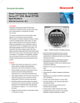
Honeywell STT 3000 SMART TEMPERATURE TRANSMITTER Models STT350 and STT35F EN0I-5222 2/02 PRODUCT SPECIFICATION SHEET OVERVIEW Honeywell’s microprocessor based STT350/ 35F Smart Temperature Transmitters convert a primary sensor input TM into a standard 4-20mA or FOUNDATION Fieldbus output signal on a 2 wire signal plus power loop connection. These universal temperature input models readily accept signals from a wide variety of industry standard thermocouples (T/Cs) or resistance temperature detectors (RTDs) as well as basic milliVolt or Ohms sensors. The output signal is either proportional to the measured variable or linearised to temperature. For the STT350, the output is transmitted in either an analogue 4-20mA format or a digital DE protocol format for X ® direct digital integration to the TPS/ TDC 3000 control system. You easily select the analogue or digital format for the output signal transmission through the Smart Field ® Communicator (SFC) which is the common hand held operator interface for our Smartline™ Transmitters. All configuration, operation and communication functions are under the control of the STT350’s microprocessors and are implemented through the SFC or the PC based Smart Configuration Toolkit (SCT). For the STT35F, the output conforms to the low speed (H1) of the Fieldbus Physical Layer specification IEC 11582 (1993). The other protocol layers conform to the TM FOUNDATION Fieldbus which is supported by all the worldwide instrumentation suppliers and enables multidrop field instruments to be powered down a single wire pair and communicate measurement, control, configuration and diagnostic data at 31.25kbps. Figure 1 – STT350 Transmitter in field mount housing. The Model STT35F is identical in size but details vary. COMMON FEATURES • • • • • • Single model accepts input signals from a choice of primary sensors to satisfy varying applications requirements with minimum transmitter inventory. Standard digital cold-junction compensation function provides accurate and reliable temperature measurement over a wide ambient operating range. Added Smart features include reading of the highest and lowest inputs, external cold junction compensation temperature at an isothermal block and engineering units displayed in degrees C, F, K, or R plus milliVolt and Ohms. Smart transmitter personality with local or remote interfacing means significant manpower efficiency improvements in commissioning, start-up, and ongoing maintenance functions. Write protect link included to safeguard configuration settings. Includes sensor break detection on all input wires. Post read validation of the measured signal before providing fresh output. • • • • • • Suitable for DIN rail mounting or remote field mounting in a flameproof housing. Provides true differential temperature measurement of thermocouple or RTD inputs by individual linearisation of each sensor reading and then computing the difference. Suitable for true 4-wire Pt100 measurement (or 3- or 2-wire). Write protect link included to safeguard configuration settings. Supports dual thermocouple sensor inputs for redundant sensor operation. Surge/ lightning protection options can be installed internally in housing or externally in conduit. Added STT35F Features • • • • • Added STT350 Features • • Direct digital integration with TDC 3000X system provides local measurement accuracy to the system level without adding typical A/D and D/A converter inaccuracies. Integral analogue or digital indicating meter option • Includes Fieldbus Foundation standard Function blocks to ensure full interoperable operation - Analog Input (AI), Control Block (PID), Resource Block (RB) and Transducer Block (XB). Includes Link Master capability to assume Link Active Scheduler (LAS) role of controlling the deterministic message communications in the event of primary LAS loss. Integral Digital Meter available without the need for an additional bus connection or power. Fieldbus Simulate link available for loop commissioning/ troubleshooting. Includes Flash Memory for ease of software upgrade over the fieldbus for changes or improvements in this emerging technology. Configuration of the STT35F Function Blocks and the Fieldbus Application Parameters can be done with the National Instruments Configuration Toolkit or any other Fieldbus Foundation registered configurator. DESCRIPTION The STT350 and STT35F transmitters are suitable as a direct replacement for any conventional or Smart temperature transmitter in use today. Their memory contains the characteristics of most commonly used temperature sensors. This means that you can use the configuration tool to configure the transmitter for any of these sensors and it will automatically correct for their associated non-linearity’s. The transmitter module can also be installed on a standard DIN rail (to EN50022) or remotely mounted in a flameproof housing designed for either surface or two-inch pipestand mounting. Transmitters can be preconfigured at the factory to your exact specifications or they will be shipped with factory default configuration - ready to accept your own configuration. Model STT35F Model STT350 You make all transmitter adjustments and diagnostic checks through an SFC connected anywhere across the 4-20mA wire route. This lets you initiate configuration and maintenance functions at locations remote from the transmitter itself. The SFC is also fully compatible with all other Honeywell Smartline Transmitters. When digitally integrated to TPS/ TDC 3000X ® the operator or maintenance engineer has access to the transmitter database and diagnostics in addition to the measure signal being transferred as a digital PV in floating point high resolution. The system maintains a copy of the transmitter database for security of verification of any field initiated changes. In the event of unauthorized changes the system treats the PV as a fault condition until the operator restores the original configuration. The H1 low speed FOUNDATION Fieldbus protocol is aimed at the replacement of 420mA conventional or Smart transmitters by multidrop digital field devices with signal and power carried over a single wire pair and also meeting intrinsic safety requirements. Configuration of the field devices and the bus operating parameters can be performed from the system console or from Windows 95 or NT PC based configuration tools such as the National Instruments Configurator. The driving force behind fieldbus is increased field intelligence and capabilities and these result in a wide range of available configuration selections such as the gain , integral, derivative settings in the PID control block, or its mode of operation Manual, Automatic or cascade, or built in alarm settings etc. Performance under Rated Conditions Digital Accuracy for Maximum Range Limits RTD: Pt100 % of Max Span °C °F Digital Accuracy for Normal Range Limits °C °C °F 0.01 -200 to 850 -328 to 1562 0.1 -200 to 450 -328 to 842 Pt200 0.01 -200 to 850 -328 to 1562 0.1 -200 to 450 -328 to 842 IEC751:1986(α=0.00385) IEC751:1986(α=0.00385) Input Type Maximum Range Limits Normal Range Limits Standards Pt500 0.02 -200 to 850 -328 to 1562 0.1 -200 to 450 -328 to 842 IEC751:1986(α=0.00385) Pt100J 0.01 -200 to 640 -328 to 1184 0.1 -200 to 450 -328 to 842 Ni500 0.04 -80 to 150 -112 to 302 0.1 -50 to 150 -58 to 302 JISC 1604-81(α=0.00392) Honeywell Type A Cu 10 0.37 -20 to 250 -4 to 482 1.0 -20 to 250 -4 to 482 General Electric Cu 25 0.19 -20 to 250 -4 to 482 0.5 -20 to 250 -4 to 482 General Electric T/C: B 0.14 200 to 1820 392 to 3308 1.0 550 to 1820 1022 to 3308 IEC 584-1 (ITS-90) C 0.03 0 to 2300 32 to 4172 0.6 0 to 1650 32 to3002 IPTS 68 D 0.03 0 to 2300 32 to 4172 0.6 330 to 1370 626 to 2498 IPTS 68 E 0.04 -200 to 1000 -328 to 1832 0.2 0 to 1000 32 to 1832 IEC 584-1 (ITS-90) J 0.04 -200 to 1200 -328 to 2192 0.2 0 to 800 32 to 1472 IEC 584-1 (ITS-90) K 0.04 -200 to 1370 -328 to 2498 0.3 -120 to 1370 -191 to 2498 IEC 584-1 (ITS-90) N 0.06 -200 to 1300 -328 to 2372 0.3 0 to 1300 32 to 2372 IEC 584-1 (ITS-90) IEC 584-1 (ITS-90) R 0.09 -50 to 1760 -58 to 3200 0.5 500 to 1760 932 to 3200 S 0.08 -50 to 1760 -58 to 3200 0.5 500 to 1760 932 to 3200 IEC 584-1 (ITS-90) T 0.14 -250 to 400 -418 to 752 0.2 -100 to 400 -148 to 752 IEC 584-1 (ITS-90) NiNiMoly 0.03 0 to 1300 32 to 2372 0.3 780 to 1300 1436 to 3272 G.E. (IPTS - 68) Radiamatic 0.6 420 to 1800 788 to 3272 0.7 780 to1800 1436 to 2372 Honeywell (RH) milliVolts 0.01 -20 to 120mV 8uV -10 to 45 mV Ohms 0.01 0 to 2000Ohms 0.15Ohms 0 to 2000Ohms Note that the above Accuracy values are available merely by selecting the sensor type and range (i.e. without user calibration). Improvements of up to 2 times can be obtained for the accuracy by calibrating to the required LRV/URV values with simulated inputs from a calibrator box. All STT350 units pass through 20 hours of Environmental Stress Screening (ESS) by fast cycling between -40 and +85°C to ensure maximum product reliability. During this ESS process, the ambient temperature compensation coefficients are determined for individual units and burned in transmitter memory to provide maximum performance over a wide range of operating conditions. 2 EN0I-5222 11/01 SPECIFICATIONS Operating Conditions Parameter Reference conditions Rated Condition Operative limits Transportation and storage Ambient temperature 23°C ± 2 73°F ± 4 -40 to 85°C -40 to 185°F -40 to 85°C * -40 to 185°F -50 to 100°C -58 to 212°F 10 to 55 10 to 55 5 to 95 5 to 100 5 to 100 5 to 100 5 to 100 5 to 100 Humidity Rack Mounting %RH Mounted in EP %RH housing Model STT350 Model STT35F 10.8 to 42.4 Vdc at the transmitter terminals 9.0 to 35Vdc at the transmitter terminals 0 to 1450 Ohms (as shown in Fig 2) Dependent on number/ type of bus devices. Maximum of 4g over 15 to 200Hz. (restricted to 3g with indication meter) Maximum of 40g * = Short term operative limit of -50°C (-58°F) Supply Voltage and load Resistance Vibration Shock Output D/A Accuracy** Cold Junction Accuracy Total Reference Accuracy In Analogue Mode** = In Digital Mode = Digital Ambient Temperature Effect (per 10°C change from 20°C reference) Cold Junction Rejection Effect Output D/A Ambient Temperature Effect** Total Output Ambient Temperature Effect (ATE) In Analogue Mode** = In Digital Mode = Power Supply Voltage Effect ±0.025% of span** ± 0.25°C Digital Accuracy of input + Output D/A Accuracy** + CJ Accuracy (T/Cs only) Digital Accuracy of input + CJ Accuracy (T/Cs only) (example: transmitter operating in Analogue Mode with Pt100 sensor and 0 to 200°C Total Reference Accuracy = 0.1 + (200 x 0.025) = 0.15°C 100 RTDs or Ohms : 0.029% of reading T/Cs or mV : 0.042% of reading 60:1 for changes from 23°C ambient 0.045% of span per 10°C change** Digital ATE + Output D/A ATE** + CJ ATE (T/Cs only) Digital ATE + CJ ATE (T/Cs only) 0.005% of span per Volt ** = Not applicable for Model STT35F or for STT350 used in digital DE output mode. Parameter Description Adjustment Range Output (2 wire) STT350 STT35F Damping time constant Thermocouple Burnout Input to output galvanic isolation Input & output common mode isolation Common Mode Rejection Series Mode Rejection EMC compliance RFI Rejection Stability/Time Drift EN0I-5222 11/01 No limits to adjustments between the Maximum range and 1 eng. unit e.g. 1°C 4-20mA or Honeywell DE digital protocol Extended range: 3.8-20.8mA. Fail safe modes <3.8mA or 21.8mA IEC 1158-2 low speed H1 signaling in Manchester bi-phase L at 31.25kbps. Adjustable from 0 to 102 seconds digital damping Burnout detection is user selectable Upscale or downscale with critical status message on STT350. Meets dielectric strength test of 1400Vac rms (50/60Hz) 2,000Vdc for 1 minute. Withstands dielectric test of 700Vac rms or 1,000 Vdc for 1 minute. 120dB (1 million to 1) from 50Hz to 50kHz 40dB (100 to 1) for 50 or 60Hz ±0.5Hz (with internal software filter set to local power line frequency) In compliance with 89/336/EEC, Electro Magnetic - Compatibility (EMC) Directive ±0.1% of span at 30V/m over 20 to 1,000MHz in explosion proof housing with shielded cables 0.05% of maximum span per year. Autocalibration against internal reference every second 3 Physical Mounting, Construction and Approvals Description DIN rail (top hat or G rail) Explosion Proof/Flame Proof housing with surface mounting or 2-inch pipe mounting (IP 66/NEMA 4X Rating) The FM/CSA explosion proof housing meets the applicable requirements of NEMA 7 and 9 Screw Terminals - M3.5x6.7mm nickel coated brass. Accepts up to Wiring 12AWG, 16AWG recommended Transmitter for DIN rail mount - 0.5kg (1.1 pounds) Net Weight Transmitter in EP or XC housing - 1.6kg (3.6 pounds) Transmitter + indicator in housing - 2.4kg (5.2 pounds) Transmitter module - Aluminium housing with baked on Materials of construction polyester paint cover. Noryl terminal block. EP housing – Aluminium housing with baked on epoxy-polyester hybrid paint cover (beige) XC housing - Aluminium housing with baked on 2 coats epoxy resin cover (beige) ST02 housing - Aluminium housing with baked on 2 coats epoxy resin cover (red) 316 Stainless Steel housing available as a special. See Fig 3 Dimensions 1/2 inch NPT electrical connection with optional Sensor/ cable entry adapters for M20x1.5, or 3/4 inch NPT (EP, XC or ST02 housing) CENELEC Intrinsically Safe EEx ia IIC T4/ T5/ T6 with Safety Approvals STT350 Module 30V/100mA/1.2W barrier (T4/ T5/ T6 = -20 to +80/ +50/ + 40 °C ambient) Intrinsically Safe Class I, Div.1, Groups A to D (STT35F Pending) CSA Intrinsically Safe Class I, II, III, Div. 1, Groups A to G. FM Non-Incendive Class I, Div. 2, Groups A to D FM Suitable for Class II, III, Div. 2, Groups F and G GOSSTANDARD Tested and approved by Russian Certificate of pattern Approval No 2064 of January, 1998 Additional approvals With or without Integral Meter Zone 2: T6, 28V/22mA With EP, XC or CENELEC Flame Proof EEx d IIC T6 ST02 housings CSA Explosion Proof Class I, II, III, Div. 1, Groups B to G FM Explosion Proof Class I, II, III, Div. 1, Groups B to G Without Integral Meter FM Explosion Proof Class I, II, III, Div. 1, Groups A to G Internal SP selection 10 kA peak current (8/ 20 µs waveform), 10kV peak Voltage (10/ 50 µs Surge/ Lightning waveform) protection options External LP selection 10 kA peak current (10/ 20 µs waveform), 500A peak current (10/ 1000 µs waveform) Parameter Mounting 4 EN0I-5222 11/01 Parameter Thermowell & Probe Availability Description STT350 can be supplied integrally mounted with any of the previously listed standard resistance temperature devices (RTDs) and thermocouple (TCs) elements. Probe Types: • 1/4" Rigid or spring loaded RTDs or T/Cs in Inconel or Stainless Steel sheaths in standard lengths from 3" to 24" (other lengths by request). • Standard or heavy duty service. • Locally mounted to the STT350 housing or remotely mounted into explosion-proof mounting heads. • With (or without) probe lag hardware : Hex nipple, Straight nipple or Double lag and Union connections. • Single or dual element availability; grounded or ungrounded • Additionally, the following types of Thermowells can also be provided as an integral thermal solution : Thermowell Materials: Carbon Steel, 304SS, 316SS, 316L SS, 446SS, Hastelloy B, Hastelloy C, Monel, Inconel 600 (other materials by request). Thermowell Types: Threaded well, Flanged well, or Socket well, (with or without thermowell lag extensions). Flange Types: Raised Face, Flat Faced and Ring Type Joint flange availability in 1", 1.5", 2" or 3" sizes. Flange ratings: ANSI 150, 300, 600, 900 and 1500 ratings. 1450 Loop Resistance (Ohms) 250 0 10.8 Supply Voltage 42.4Vdc Note : a minimum of 250 Ohms of loop resistance is required to support communications. Loop resistance is the total of loop wiring resistance, safety barrier and receiving device input developing resistor. The triangle outlined by the heavy lines alongside shows the operating area for field wiring and barrier resistance beyond the 250 Ohms necessary for communications. If a Smart Meter is included in the loop, allow an additional 2.25Volts for meter power. If surge lightning protection is included this adds 44 Ohms to the loop resistance i.e. allow 1 Volt additional supply or reduced loop wiring power. Figure 2 - STT350 Supply Voltage versus Load Resistance EN0I-5222 11/01 5 Model Selection Guide Model Selection Guide 34-44-16-02 Issue 8 34-44-16-02 Honeywell Confidential & Proprietary Instructions Select the desired Key Number. The arrow to the right marks the selection available. Make one selection from each table using the column below the proper arrow. A dot denotes unrestricted availability. A letter denotes restricted availability. Restrictions follow Table VII. Key Number STT35_ I - _ II - ____ - III ____ IV - _______ V - ___ KEY NUMBER selections made. VI VII - ____ - ____ Selection Description STT350 Smart Temperature Transmitter Module (4-20mA/DE) STT35F Fieldbus Temperature Transmitter Module All modules carry the following approvals: Intrinsically Safe for Class I, Div. 1, FM: Groups A,B,C & D * Non-Incendive for Class I, Div. 2, Groups A,B,C,D CSA: Intrinsically Safe for Class I, II, III, Div. 1, Groups A,B,C,D,E,F,G CENELEC: Intrinsically Safe for EEx ia IIC T4/T5/T6 CE Mark: All modules carry CE Mark and are in compliance with EN 50081-2 and 50082-2. Russian Certificate of Pattern Approval No. 2064 of Jan. 1988. List Price equals the sum of all prices of all Availability STT350 STT35F * Use of STT350/35F within Class II or III, Division 1 or 2, Groups E, F and G requires the use of explosionproof field mount housing option. TABLE I - Sensor Probe and Thermowell Accessories No Integral Sensor Probe or Thermowell Supplied (1) Sensor Probe and/or Thermowell mounted or tested with STT 3000 0 1 j j TABLE II - Transmitter Housing and Integral Meters (Select approval body certification in Table VII) No Housing Supplied 00 _ _ Explosion-Proof Explosion-Proof Housing Field Mount - with baked on beige polyester/epoxy hybrid paint EP _ _ (2) Housing - with beige epoxy paint XC _ _ For Stainless Steel or Red Epoxy Painted Housing, select Table II EP _ _ and appropriate Table VI code. No Meter Supplied _ _ 00 Analog Meter _ _ ME (3) _ _ SM Integral Meter Smart Meter j _ _ FM Fieldbus Smart Meter (1) (2) j Specify 8 digit customer I.D. when probe/well selected. See Price Pages 13:TP-1 to 16 for sensor/well selections and pricing. With a housing, 20 characters max. of customer information is available on the nameplate at no charge. (See 13:STT-OE-5 for ordering instructions.) (3) Remote Meter available as Model RMA300 (See Price Page 13:RM-1.) Industrial Automation and Control Division, 16404 North Black Canyon Highway, Phoenix, AZ 85053 Printed in U.S.A. 6 Copyright 2001 - Honeywell Inc. EN0I-5222 11/01 Model Selection Guide, continued 34-44-16-02 Availability STT35 _ TABLE III - Configuration & Tagging Configuration None - Factory Default Configuration Supplied Transmitter Configuration (see 13:STT-OE-5 for choices) No Tagging Requested 316 SS Wired-on Customer I.D. Tag - (4 lines, Customer (4) Tagging 28 characters per line, customer specified information) 316 SS Wired-on Customer I.D. Tag (blank) TABLE IV - Optional Equipment No Mounting Arrangement Supplied DIN Rail Mounting via 2 Clips (to Top Hat or "G" Rail) Mounting Arrangement Carbon Steel Mounting Bracket for 2" Pipe 316 SS Conduit Adaptor for Wiring Entry Lightning Stainless Steel Mounting Bracket for 2" Pipe No Adaptor(s) Supplied - 1/2" NPT Conduit Connection 1/2" NPT to M20 x 1.5 1 Adaptor (EEx d IIC Approved) 2 Adaptors 1/2" NPT to 3/4" NPT 1 Adaptor No Lightning Protection Supplied Protection External Lightning Protection - Mountable to Housing Operator's/User's Manual Internal Surge/Lightning Protection None English Version (for STT35F Only) - 1 manual for 5 units English Version (for STT350 Only) - 1 manual for 5 units French Version (1 manual for 5 units) Spanish Version (1manual for 5 units) TABLE V - Optional Extended Warranty Coverage & Certificates Standard Warranty Optional Additional Warranty - 1 year Extended Additional Warranty - 2 years Warranty Additional Warranty - 3 years Optional (5) Certificate No Transmitter Configuration/ Calibration Certificate Transmitter Configuration/ Calibration Certificate (5) 0 F 00 _ _ TC _ _ _ _ 00 _ _ TG j j _ _ TB j j 00 _ _ _ _ _ DR _ _ _ _ _ MB _ _ _ _ _ SB _ _ _ _ _ __0____ __1____ __2____ __3____ _ _ _ 00 _ _ _ _ _ LP _ _ k j k j _ _ _ SP _ _ _ _ _ _ _ 00 _ _ _ _ _ EF _ _ _ _ _ EN _ _ _ _ _ FR _ _ _ _ _ SP j j c c c c j j j j _0_ _D_ __0 C 0__ 1__ 2__ 3__ (D-0097-RD.A) No Certificate of Conformance/ Origin Certificate of Conformance/ Origin (D-0098-RD.A) (4) (4) Selection Replaces Selection _ _ _ _ _US Installation Guide, chosen Operator's Manuals and chosen Certificates are automatically shipped with unit. See 13:STT-OE-7 for additional manuals and alternate shipping. EN0I-5222 11/01 7 Model Selection Guide, continued 34-44-16-02 Availability STT35 _ TABLE VI - Additional Features No Selection Red Epoxy Painted Housing Cap (5) Red Epoxy Painted Explosion-Proof Housing (5) 316 Stainless Steel Explosion-Proof Housing (5) Selection 0000 ST01 ST02 ST07 0 F j g g j g g Must be ordered with Table II EP _ _. Pricing Table A Table VI Table II ST07 EP00 EPME EPSM EPFM TABLE VII - Safety Approval Body Selection Appearing on Housing Nameplate Approval Body Approval Type Location or Classification None No explosion-proof or flame-proof 00 approval body certifications included Explosion-Proof Class I, Div. 1, Groups A,B,C,D Dust Ignition-Proof Class II, III Div. 1, Groups E,F,G Intrinsically Safe Class I, II, III, Div. 1, Groups A,B,C,D,E,F,G 1C Non-Incendive Class I, Div. 2, Groups A,B,C,D Suitable for Class II, III, Div. 2, Groups F, G Explosion-Proof Class I, Div. 1, Groups B,C,D Dust Ignition-Proof Class II, III, Div. 1 Groups E,F,G Factory Intrinsically Safe Class I, II, III, Div. 1, Mutual Groups A,B,C,D,E,F,G 1J Non-Incendive Class I, Div. 2, Groups A,B,C,D Suitable for Class II, III, Div. 2, Groups F, G Intrinsically safe Class I, Division 1, Groups A,B,C,D 1G Intrinsically safe Class I, Zone 0&1, AEx ia IIC Non-Incendive Class I, Division 2, Groups A,B,C,D Intrinsically safe Class I, Division 1, Groups A,B,C,D 1G Non-Incendive Class I, Division 2, Groups A,B,C,D Explosion-Proof Dust Ignition-Proof CSA Intrinsically Safe Intrinsically safe 8 Class I, Div. 1, Groups B,C,D Class II, Div. 1, Groups E,F,G Suitable for Class III, Div. 1 & 2, Groups E,F,G CSA Enclosure 4 Class I, II, III, Div. 1, Groups A,B,C,D,E,F,G Class I, Division 1, Groups A,B,C,D Class II, Groups E,F,G, Class III, Division 1 Flame-Proof CENELEC Intrinsically Safe Intrinsically Safe SelfZone 2 Certified EEx d IIC T6 EEx ia IIC T6/T5/T4 EEx ia IIC T6/T5/T4 T6, 28v/22mA Australia Ex ia IIC T4 (70 C ambient) Intrinsically Safe o f f j j m m 2J j a 2S m m 3D 3S 3N j j j j 4S EN0I-5222 11/01 Model Selection Guide, continued RESTRICTIONS Restriction Letter Table a II c Available Only With Selection Approval Pending EP _ _, XC _ _ EP _ _, XC _ _ f II g II EP _ _ j II EP _ _, XC _ _ k m II 0000 Note: Table 34-44-16-02 Not Available With Selection II 2J, 1C, 1J _ _ SM, _ _ FM II EP _ _, XC _ _ II See 13:STT-9 and User's Manual for part numbers. See 13:STT-OE-5 for OMS Order Entry Information including tagging, transmitter configuration, manuals, certificates, drawings and SPINS. To request a quotation for a non-published "special", fax RFQ to Marketing Applications at 602 313-6155. Fig 3. STT350/35F transmitter and optional flameproof housing dimensions – reference only EN0I-5222 11/01 9 Distributor : Honeywell Industrial Automation and Control Honeywell Inc. U.S.A. : Honeywell Industrial Automation and Control, 16404 North Black Canyon Hwy., Phoenix, AZ 85023 Canada : The Honeywell Centre, 155 Gordon Baker Rd., North York, Ontario M2H 3N7 Latin America : Honeywell Inc., 480 Sawgrass Corporate Parkway, Suite 200, Sunrise, Florida 33325 Japan : Industrial Operations Tokyo, 4-28-1 Nishi-Rokugo Othu-ku, Tokyo 144, Japan, Asia Pacific: Honeywell Asia Pacific Inc., Honeywell Building, 17 Changi Business Park, Central 1, Singapore 486073. (65) 355 2828 Northern Europe and Southern Africa : Honeywell Ltd., Honeywell House, Arlington Business Park, Bracknell, RG 12 1 EB, U.K. Central Europe : Honeywell A.G., Kaiserleistraße 39, 63067 Offenbach, Germany Western and Southern Europe : Honeywell S.A., 3 Avenue de Schiphol 3, 1140 Brussels, Belgium Eastern Europe : Honeywell Praha, s.r.o., Budejovicka1, 140 00 Prague 4, Czech Republic Middle East : Honeywell Middle East Ltd., Khalifa Street, Sheikh Faisal Building, Abu Dhabi, U.A.E. 10 EN0I-5222 11/01