1
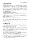
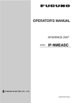
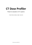
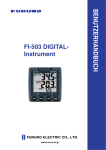
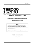
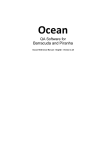
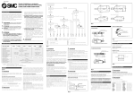
STE 58764
CHAPTER 2
INSTALLATION
2.1
INSTALLATION ENVIRONMENT
Table 2.1 shows the environmental conditions for the location in which the SR-HSP Series Robot
and SR7000 Controller are to be installed.
Table 2.1 Environmental Conditions for the Robot and Controller
Specifications
In operation
: 0 to 40 ℃
In storage
: -10 to 50 ℃
Humidity
20 to 90 % (Non-condensing)
Do not install the robot where it may be subject to fluids such as water.
Altitude
1000 m or less
2
Vibration
In operation
: Within 0.98m/s
2
In transport
: Within 9.8m/s
Dust
There is to be no inductive dust.
Please consult with Toshiba first should you wish to use the robot and
controller in an especially dusty environment.
Gas
There is to be no corrosive or combustible gas.
Sunlight
The robot must not be subject to direct sunlight.
Electromagnetic
There are to be no devices in the area which produce an excessive
noise
amount of electromechanical noise.
Field
There are to be no devices in the area that generate a strong field.
Item
Temperature
Danger
Do not place the robot near combustible matters.
Doing so could lead to fires if the matter ignites due to a fault, etc.
・
2.2
ROBOT INSTALLATION
Before actually installing the robot, you must plan a layout and take into consideration such
matters as the working space, coordinate system and space for maintenance.
2.2.1
External Dimensions
An outline drawing of the robot is shown in Figs. 2.1 to 2.5.
- 2-1 -
STE 58764
Fig. 2.1 External view of SR-504HSP robot
- 2-2 -
STE 58764
Fig. 2.2 External view of SR-554HSP robot
- 2-3 -
STE 58764
Fig. 2.3 External view of SR-654HSP robot
- 2-4 -
STE 58764
Fig. 2.4 External view of SR-854HSP robot
- 2-5 -
STE 58764
Fig. 2.5 External view of SR-1054HSP robot
- 2-6 -
STE 58764
Working Space
Figs. 2.6 to 2.10 show the working space of the robot. Each axis can operate within the
working space. To keep the robot from moving out of the working space by mis-operation,
the robot is equipped with mechanical stoppers outside the moving range. In addition,
soft limits are provided which may be set as desired by the user.
110°
R500
R184
137°
137°
110°
150
R250
100
2.2.2
Fig. 2.6 SR-504HSP robot working space
- 2-7 -
STE 58764
115°
R193
R550
200
120°
120°
100
115°
Fig. 2.7 SR-554HSP robot working space
115°
R227
140°
140°
200
R650
100
115°
Fig. 2.8 SR-654HSP robot working space
- 2-8 -
STE 58764
115°
R350
145°
R850
200
145°
110
115°
Fig. 2.9 SR-854HSP robot working space
115°
R333
145°
115°
150
145°
200
R1050
Fig. 2.10 SR-1054HSP working space
- 2-9 -
STE 58764
Coordinate System
The robot's joint angle zero point (0° or 0mm position) has been calibrated before
shipment in respect to the base reference planes. The base coordinate system will be
determined according to this calibration. Figs. 2.11 to 2.15 show the base coordinate
system and the zero positions of each axis joint angle.
(-)
XB
Axis 4
0°
(+)
(-)
0°
(-)
0°
(+)
Axis 2
250
Reference plane
180
Reference plane
(+)
Axis 1
90
250
YB
ZB
Axis 3
Origin of base
coordinate system
(+)
0mm
◎
100
2.2.3
Fig. 2.11 SR-504HSP base coordinate system and joint angle zero point
-2-10-
STE 58764
Reference plane
(-)
(-)
210
(-)
XB
Axis 4 (+)
Reference plane
Axis 2 (+)
300
(+)
Axis 1 250
105
YB
ZB
Axis 3
XB
(+)
Origin of base
coordinate system
0mm
◎
View A
100
View A
Fig. 2.12 SR-554HSP base coordinate system and joint angle zero point
- 2-11 -
STE 58764
Reference plane
0°
XB
(-)
(-)
210
(-)
Reference plane
0°
0°
Axis 4
(+)
(+)
Axis 2
Axis 1
300
(+)
105
350
YB
ZB
XB
Axis 3
(+)
Origin of base
coordinate system
View A
0mm
100
◎
View A
Fig. 2.13 SR-654HSP base coordinate system and joint angle zero point
-2-12-
STE 58764
Reference plane
(-)
0°
XB
Axis 4
0°
(+)
(+)
Axis 2
210
(-)
Reference plane
(-)
0°
Axis 1 (+)
300
105
550
YB
ZB
Axis 3
XB
(+)
View A
0mm
◎
110
View A
Origin of base
coordinate system
Fig. 2.14 SR-854HSP base coordinate system and joint angle zero point
-2-13-
STE 58764
Reference plane
(-)
300
(-)
(-)
0°
0°
XB
Reference plane
0°
(+)
Axis 4
Axis 2 (+)
Axis 1 (+)
150
470
580
YB
ZB
Axis 3
XB
(+)
0mm
◎
Origin of base
coordinate system
150
View A
View A
Fig. 2.15 SR-1054HSP base coordinate system and joint angle zero point
-2-14-
STE 58764
2.2.4
Installing the Robot
The robot is fastened down using the mounting holes in the base.
Use M12 hexagon socket bolts for the SR-504HSP and M16 hexagon socket bolts for the
SR-554HSP, SR-654HSP, SR-854HSP and SR-1054HSP.
The robot installation method is shown in Figs. 2.16 to 2.18. A reference plane is
prepared on the base section and is marked with "xxx".
To align the robot's base coordinate system position or when the robot must be replaced,
prepare an adequate reference plane. Then, contact that reference plane to the base
reference plane and fasten. The reference plane has been coated with anticorrosive
agents before shipment, so wipe the agent off with thinner before using.
Caution
・
・
The robot will suddenly accelerate and decelerate during operation, so when installing it on
a frame, make sure that the frame has sufficient strength and rigidity.
If the robot is installed on a frame that does not have sufficient rigidity, the vibration will
occur while the robot is operating, and could lead to faults.
When installing the robot on the floor, fasten the robot down securely with foundation bolts.
Install the robot on a level place.
Failure to do so could lead to a drop in performance or faults.
Reference plane
180
130
65
××
M12 hexagon
socket bolt
4-φ14hole
φ24depth counterbore
130
×
××
Reference plane
90
30
20
×
140
Fig. 2.16 Installing the SR-504HSP robot
-2-15-
STE 58764
Reference plane
M16 hexagon
socket bolt
160
4-φ18 hole,counterbore 26
×××
105
160
105
×
×
××105
40
104
160
25
Reference plane
Fig. 2.17 Installing the SR-554HSP,SR-654HSP, SR-854HSP robot
Reference plane
240
4-φ18 hole,counterbore 26
×××
×
×
150
240
150
M16 hexagon
socket bolt
××××
150
148
40
Reference plane
25
×
×
185
Fig. 2.18 Installing the SR-1054HSP robot
-2-16-
STE 58764
INSTALLING THE CONTROLLER
External Dimensions
20.5
An external view of the controller is shown in Fig 2.19.
381
330
Right side
Top
230
241
430
11
2.3.1
30.5
2.3
Front
Rear
Fig. 2.19 External view of the controller
-2-17-
STE 58764
2.3.2
Rack Mounting Dimensions
When mounting the SR-7000 robot controller in a rack, set the side brackets using the
screw holes provided on both ends of the front panel, and secure the controller to the rack.
(① in Fig. 2.20: Side brackets are optional.)
10
460
10
40
4-R3
①
①
11
40
150
Adaptive screw
diameter
5mm
Fig. 2.20 Dimensions of controller rack mounting holes
2.3.3 Precautions for Rack Mounting
Pay attention to the following when rack mounting the SR-7000 robot controller.
(1) When mounting the controller in a rack, use the screw holes provided at both ends of
the front panel, and fix the controller. (Optional side brackets are required.)
Caution
・
If the rack is completely sealed, provide holes to allow the air to be let out, forcibly ventilate
the rack with a fan or cool it indirectly so that the heat will not be trapped in the rack.
If the heat is trapped in the rack or controller, faults could occur.
(2) The cable connectors are connected to the rear side of the controller, so provide a
space of 110mm at the rear side.
-2-18-
STE 58764
(3) The upper cover must be removed during maintenance. (See Fig. 2.21.)
Keep this in mind when installing the controller. Specifically, the controller should be
easily removable from the rack. Practically, be careful of the following points.
(a) Arrange the cables around the rear panel of the controller (so that the controller
can be removed).
(b) Arrange the cables between the controller and the control panel when the control
panel is separated (so that the controller can be removed).
(c) Connect all the cables in a position where the robot can be operated even if the
controller is removed from the rack.
Upper cover
SR70
00
Robo
t
Cont
roll
er
Fig. 2.21 Upper cover
(4) When the controller is mounted on the rack, the weight of the controller should be
supported with the legs of the controller. Screw holes for rack mounting the
controller are used for securing the controller panel, and the weight of the controller
cannot be supported only with the screws.
(5) On the front of the controller, a clearance of approx. 90 mm should be provided for
connecting the connector of the teach pendant. Even if the teach pendant is not
used, a clearance of approx. 50 mm is required for connecting a dummy plug.
35mm
90mm
Fig. 2.22 Clearance of front panel of controller
-2-19-
50mm
STE 58764
2.3.4
Precautions for Direct Installation
When two or more controllers are used, it is necessary to provide a clearance of 50 mm or
more in the horizontal direction and a clearance of 100 mm or more in the vertical
direction between the controllers.
Caution
・
・
Provide a ventilation space at the side of the controller so that the air vent holes are not
blocked. The space equal to the length of the support should be kept below the lower
surface.
Failure to do so could cause the cooling performance to drop or to faults.
Do not stack the controllers or place objects in front of it.
SERVO POWER
OFF
EMERGENCY
J1
ON
POWER
J2
50mm or more
50mm or more
PC
STOP
START
FAULT
BATTERY
ALARM
POWER
CC24V
C.P.
EXT
INT
MANU
FDD
CYCLE STOP
TP
10AT
11mm
Fig. 2.23 Controller ventilation space
2.4
PRECAUTIONS FOR HANDLING THE TEACH PENDANT
Be careful of the following when handling the teach pendant.
Caution
・
・
・
・
・
Do not drop the teach pendant or hit it against anything.
Do not pull on the cable protruding from the teach pendant.
Do not press the switches on the teach pendant with anything sharp (like the tip of a knife,
pencil, ball-point pen, etc.).
Do not place or use the teach pendant near open flames.
Do not leave the teach pendant in direct sunlight for a long period of time.
-2-20-
STE 58764
2.5
SAFETY MEASURES
(1) When installing the robot, provide sufficient space to carry out the work safely.
(2) Clarify the hazard zone, and provide a safety fence so that other persons cannot enter the
zone easily. The hazard zone is the zone near the robot's working space where a
hazardous state could occur if a person enters.
(3) Provide a limit switch, photo switch or foot switch, etc., at the entrance of the safety fence
to provide an emergency stop function that will stop the robot if a person enters the hazard
zone. The emergency stop function should be an electrically independent b contact
(closed in normal operation) with compulsive opening function and must not be
automatically recovered.
Limit switch
Door
Warning light
Robot unit
Safety fence
Controller
Photo
switches
Foot switch
Robot working space
Line
Foot switch
Line
Photo switches
Safety fence
Warning light
Limit switch
Door
(4) The controller must be installed at a place outside the hazard zone where the operator can
view the robot movement.
-2-21-