1
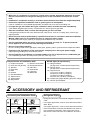
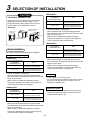
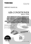
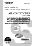
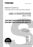
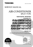
FILE NO. A03-013 SERVICE MANUAL <OWNERS MANUAL/INSTALLATION MANUAL> SPLIT TYPE RAV-SP1100UT-E RAV-SP560AT-E, RAV-SP800AT-E RAV-SP1100AT-E, RAV-SP1400AT-E R410A The type of all the indoor units described in this Service Manual is a new model, RAV-SP1100UT-E only. For the other indoor units to be combined, refer to the Service Manuals for the following models. 4-way Air Discharge Cassette type Concealed Duct type Under Ceiling type High wall type Indoor unit RAV-SM560UT-E RAV-SM800UT-E RAV-SM1400UT-E RAV-SM561BT-E RAV-SM801BT-E RAV-SM1101BT-E RAV-SM1401BT-E RAV-SM561CT-E RAV-SM801CT-E RAV-SM1101CT-E RAV-SM1401CT-E RAV-SM560KRT-E RAV-SM800KRT-E Service Manual No. A02-013 A02-013 A03-003 A03-007 A03-007 A03-007 A03-007 A03-015 A03-015 A03-015 A03-015 A02-013 A02-013 PRINTED IN JAPAN, Feb.,2004 ToMo ADOPTION OF NEW REFRIGERANT This Air Conditioner is a new type which adopts a new refrigerant HFC (R410A) instead of the conventional refrigerant R22 in order to prevent destruction of the ozone layer. WARNING Cleaning of the air filter and other parts of the air filter involves dangerous work in high places, so be sure to have a service person do it. Do not attempt it yourself. The cleaning diagram for the air filter is there for the service person, and not for the customer. –2– Indoor Unit (4-Way Air Discharge Cassette Type) –––––––––––––––––––––––– RAV-SP1100UT-E ACCESSORIES (SOLD SEPARATELY) ............................... 4 ADJUSTMENT OF WIND DIRECTIONd ............................ 11 PRECAUTIONS FOR SAFETY ............................................ 4 TIMER OPERATION ........................................................... 12 PARTS NAME ....................................................................... 6 MAINTENANCE .................................................................. 14 PARTS NAME OF REMOTE CONTROLLER ....................... 7 AIR CONDITIONER OPERATIONS AND PERFORMANCE ... 15 CORRECT USAGE ............................................................... 9 RE-INSTALLATION ............................................................ 16 AUTOMATIC OPERATION (Auto Changeover) ................ 10 TROUBLES AND CAUSES ................................................ 16 INSTALLATION MANUAL Accessory parts and Parts to be procured locally ........ 18 1 2 3 4 PRECAUTIONS FOR SAFETY .................................... 19 SELECTION OF INSTALLATION PLACE ................... 21 DRAIN PIPING WORK ................................................. 26 5 6 7 8 RAV-SP1100UT-E OWNWE’S MANUAL ELECTRICAL WORK ................................................... 30 TEST RUN ................................................................... 33 TROUBLESHOOTING ................................................. 34 MAINTENANCE ........................................................... 35 REFRIGERANT PIPING AND EVACUATING .............. 28 RAV-SP560AT-E, RAV-SP800AT-E INSTALLATION MANUAL PRECAUTIONS FOR SAFETY .................................... 36 ACCESSORY AND REFRIGERANT ........................... 37 SELECTION OF INSTALLATION ................................ 38 5 6 7 EVACUATING ............................................................... 45 5 6 7 EVACUATING ............................................................... 58 ELECTRICAL WORK ................................................... 47 FINAL INSTALLATION CHECKS ................................ 48 REFRIGERANT PIPING .............................................. 43 RAV-SP1100AT-E, RAV-SP1400AT-E INSTALLATION MANUAL 1 2 3 4 PRECAUTIONS FOR SAFETY .................................... 50 ACCESSORY AND REFRIGERANT ........................... 51 SELECTION OF INSTALLATION ................................ 52 ELECTRICAL WORK ................................................... 60 FINAL INSTALLATION CHECKS ................................ 61 RAV-SP1100AT-E RAV-SP1400AT-E 1 2 3 4 RAV-SP560AT-E RAV-SP800AT-E Outdoor Unit ––––––––––––––––––––––––––––––––––––––––––––––––––––––––– REFRIGERANT PIPING .............................................. 56 Accessories –––––––––––––––––––––––––––––––––––––––––––––––––––– REMOTE CONTROLLER FOR AIR CONDITIONER (SPLIT TYPE) <Wireless Type> TCB-AX21U (W)-E .......................................... 63 WEEKLY TIMER FOR AIR CONDITIONER (SPLIT TYPE) <Program Weekly Timer Type> RBC-EXW21E ................................................. 72 REMOTE CONTROLLER FOR AIR CONDITIONER <Simple Operation Type> RBC-AS21E .................................................... 78 INSTALLATION MANUAL Standard Remote Controller Simple Remote Controller Program Weekly Timer Remote sensor Remote Controller Wireless Kit Network Adapter for Air Conditioner (Use for Indoor Unit Only) RBC-AMT21E ................................................. RBC-AS21E .................................................... RBC-EXW21E ................................................. TCB-TC21LE .................................................. TCB-AX21U (W)-E .......................................... 81 82 83 84 85 TCB-PCNT20E ............................................... 86 ACCESSORIES OWNER’S MANUAL 1 PRECAUTIONS FOR SAFETY • • • • Ensure that all Local, National and International regulations are satisfied. Read this “PRECAUTIONS FOR SAFETY” carefully before Installation. The precautions described below include the important items regarding safety. Observe them without fail. After the installation work, perform a trial operation to check for any problem. Follow the Owner’s Manual to explain how to use and maintain the unit to the customer. • Turn off the main power supply switch (or breaker) before the unit maintenance. • Ask the customer to keep the Installation Manual together with the Owner’s Manual. CAUTION New Refrigerant Air Conditioner Installation • THIS AIR CONDITIONER ADOPTS THE NEW HFC REFRIGERANT (R410A) WHICH DOES NOT DESTROY OZONE LAYER. The characteristics of R410A refrigerant are ; easy to absorb water, oxidizing membrane or oil, and its pressure is approx. 1.6 times higher than that of refrigerant R22. Accompanied with the new refrigerant, refrigerating oil has also been changed. Therefore, during installation work, be sure that water, dust, former refrigerant, or refrigerating oil does not enter the refrigerating cycle. To prevent charging an incorrect refrigerant and refrigerating oil, the sizes of connecting sections of charging port of the main unit and installation tools are charged from those for the conventional refrigerant. Accordingly the exclusive tools are required for the new refrigerant (R410A). For connecting pipes, use new and clean piping designed for R410A, and please care so that water or dust does not enter. Moreover, do not use the existing piping because there are problems with pressure-resistance force and impurity in it. CAUTION To Disconnect the Appliance from Main Power Supply. This appliance must be connected to the main power supply by means of a switch with a contact separation of at least 3 mm. The installation fuse (25A D type ) must be used for the power supply line of this conditioner. WARNING • Ask an authorized dealer or qualified installation professional to install/maintain the air conditioner. Inappropriate installation may result in water leakage, electric shock or fire. • Turn off the main power supply switch or breaker before attempting any electrical work. Make sure all power switches are off. Failure to do so may cause electric shock. • Connect the connecting cable correctly. If the connecting cable is connected in a wrong way, electric parts may be damaged. • When moving the air conditioner for the installation into another place, be very careful not to enter any gaseous matter other than the specified refrigerant into the refrigeration cycle. If air or any other gas is mixed in the refrigerant, the gas pressure in the refrigeration cycle becomes abnormally high and it may resultingly causes pipe burst and injuries on persons. • Do not modify this unit by removing any of the safety guards or by by-passing any of the safety interlock switches. • Exposure of unit to water or other moisture before installation may cause short-circuit of electrical parts. Do not store it in a wet basement or expose to rain or water. • After unpacking the unit, examine it carefully if there are possible damage. • Do not install in a place that might increase the vibration of the unit. • To avoid personal injury (with sharp edges), be careful when handling parts. • Perform installation work properly according to the Installation Manual. Inappropriate installation may result in water leakage, electric shock or fire. 36 • When the air conditioner is installed in a small room, provide appropriate measures to ensure that the concentration of refrigerant leakage occur in the room does not exceed the critical level. • Be sure to provide grounding. Do not connect ground wires to gas pipes, water pipes, lightning rods or ground wires for telephone cables. • Conform to the regulations of the local electric company when wiring the power supply. Inappropriate grounding may cause electric shock. • Do not install the air conditioner in a location subject to a risk of exposure to a combustible gas. If a combustible gas leaks, and stays around the unit, a fire may occur. Required tools for installation work R410A (Special requirement) 1) 2) 3) 4) 5) 6) 7) 8) 9) 10) 17) Gauge manifold (Charge hose : R410A special requirement) 18) Vacuum pump (Charge hose : R410A special requirement) 19) Torque wrench 1/4 (17 mm) 16 N•m (1.6 kgf•m) 3/8 (22 mm) 42 N•m (4.2 kgf•m) 1/2 (26 mm) 55 N•m (5.5 kgf•m) 5/8 (15.9 mm) 120 N•m (12.0 kgf•m) 20) Copper pipe gauge adjusting projection margin 21) Vacuum pump adapter 2 Philips screwdriver Hole core drill (65 mm) Spanner Pipe cutter Knife Reamer Gas leak detector Tape measure Thermometer Mega-tester 11) 12) 13) 14) 15) 16) Electro circuit tester Hexagonal wrench Flare tool Pipe bender Level vial Metal saw ACCESSORY AND REFRIGERANT Accessory and Installation Parts 1 3 Protective bush Outdoor unit Installation manual x 1 (For SM800, SP560, SP800) Drain nipple 4 2 Waterproof rubber cap Guard material for passage part (For SM800, SP560, SP800) Refrigerant Piping • Piping kit used for the conventional refrigerant cannot be used. • Use copper pipe with 0.8 mm or more thickness for Ø6.4, Ø9.5, Ø12.7. Use copper pipe with 1.0 mm or more thickness for Ø15.9. • Flare nut and flare works are also different from those of the conventional refrigerant. Take out the flare nut attached to the main unit of the air conditioner, and use it. 37 RAV-SP560AT-E RAV-SP800AT-E • Install the air conditioner securely in a location where the base can sustain the weight adequately. • Perform the specified installation work to guard against an earthquake. If the air conditioner is not installed appropriately, accidents may occur due to the falling unit. • If refrigerant gas has leaked during the installation work, ventilate the room immediately. If the leaked refrigerant gas comes in contact with fire, noxious gas may generate. • After the installation work, confirm that refrigerant gas does not leak. If refrigerant gas leaks into the room and flows near a fire source, such as a cooking range, noxious gas might generate. • Electrical work must be performed by a qualified electrician in accordance with the Installation Manual. Make sure the air conditioner uses an exclusive power supply. An insufficient power supply capacity or inappropriate installation may cause fire. • Use the specified cables for wiring connect the terminals securely fix. To prevent external forces applied to the terminals from affecting the terminals. 3 SELECTION OF INSTALLATION <SP560AT-E> CAUTION Length of refrigerant pipe connected to indoor/outdoor unit <SP560AT-E, SP800AT-E only> When using an air conditioner under low outside temperature condition (Outside temp.:–5°C or lower) with COOL mode, prepare a duct or wind shield so that it is not affected by the wind. 20m or shorter *21m to 50m <Example> Discharge Fin Discharge guide Fin Suction Addition of refrigerant is unnecessary at the local site. <Addition of refrigerant> Add 20g of refrigerant for every 1m of pipe which exceeds 20m. * Caution at addition of refrigerant When the total length of refrigerant pipe exceeds 20m, add 20g/m of refrigerant and the maximum total length of pipe is 50m. (Max. amount of additional refrigerant is 600g.) Charge the refrigerant accurately. Overcharge may cause a serious trouble of compressor. Suction hood (Side) Discharge hood Suction hood (Rear side) Item Suction <SP800AT-E> Length of refrigerant pipe connected to indoor/outdoor unit Before installation 30m or shorter Be careful to the following items before installation. *31m to 50m Length of refrigerant pipe 20m or shorter *21m to 30m Item Addition of refrigerant is unnecessary at the local site. <Addition of refrigerant> Add 20g of refrigerant for every 1m of pipe which exceeds 20m. * Caution at addition of refrigerant When the total length of refrigerant pipe exceeds 20m, add 20g/m of refrigerant and the maximum total length of pipe is 30m. (Max. amount of additional refrigerant is 200g.) Charge the refrigerant accurately. Overcharge may cause a serious trouble of compressor. 20m or shorter * 21m to 50m <Addition of refrigerant> Add 40g of refrigerant for every 1m of pipe which exceeds 30m. Air purge • For air purge, use a vacuum pump. • Do not use refrigerant charged in the outdoor unit for air purge. (The refrigerant for air purge is not contained in the outdoor unit.) <SM800AT-E> Length of refrigerant pipe connected to indoor/outdoor unit Addition of refrigerant is unnecessary at the local site. * Caution at addition of refrigerant When the total length of refrigerant pipe exceeds 30m, add 40g/m of refrigerant and the maximum total length of pipe is 50m. (Max. amount of additional refrigerant is 800g.) Charge the refrigerant accurately. Overcharge may cause a serious trouble of compressor. <SM560AT-E> Length of refrigerant pipe connected to indoor/outdoor unit Item Electrical cabling • Be sure to fix the power cables and indoor/outdoor connecting cables with clamps so that they do not contact with the cabinet, etc. Item Addition of refrigerant is unnecessary at the local site. <Addition of refrigerant> Add 40g of refrigerant for every 1m of pipe which exceeds 20m. * Caution at addition of refrigerant When the total length of refrigerant pipe exceeds 20m, add 40g/m of refrigerant and the maximum total length of pipe is 50m. (Max. amount of additional refrigerant is 1200g.) Charge the refrigerant accurately. Overcharge may cause a serious trouble of compressor. 38 Installation Place Necessary Space for Installation • A place which provides a specified space around the outdoor unit. • A place where the operation noise and discharged air are not given to your neighbors. • A place that is not exposed to a strong wind. • A place that does not block a passage. • When the outdoor unit is installed in an elevated position, be sure to secure its feet. • There must be sufficient space for carrying in the unit. • A place where the drain water does not make any problem. Obstacle at rear side <Upper side is free> 150 or more 1. Single unit installation 200 or more 2. Obstacles at both right and left sides. CAUTION The height of the obstacle should be lower than the height of the outdoor unit. 150 or more 1. Install the outdoor unit at a place where discharge air is not blocked. 2. When an outdoor unit is installed in a place that is always exposed to a strong wind like a coast or on a high story of a building, secure a normal fan operation by using a duct or a wind shield. 3. When installing the outdoor unit in a place that is constantly exposed to a strong wind such as the upper stairs or rooftop of a building, apply the windproof measures referring to the following examples. 1) Install the unit so that its discharge port faces to the 500 wall of the building. Keep a distance 500 mm or more between the unit and the wall surface. 300 or more 200 or more 3. Serial installation of two or more units 150 or more 300 or more 300 or more 300 or more The height of the obstacle should be lower than the height of the outdoor unit. 500 or more <Obstacle also at the upper side> 150 or more 2) Supposing the wind direction during the operation season of the air conditioner, install the unit so that the discharge port is set at right angle to the wind direction. Obstacle at front side Strong wind 1. Single unit installation 4. Installation in the following places may result in some troubles. Do not install the unit in such places below. • A place full of machine oil. • A place full of sulfuric gas. • A place where high-frequency radio waves are likely to be generated as from audio equipment, welders, and medical equipment. 500 or more <Upper side is free> Strong wind 1000 or more 2. Serial installation of two or more units 39 3 SELECTION OF INSTALLATION <Obstacle also at the upper side> • Before installation, check strength and horizontality of the base so that abnormal sound does not generate. • According to the following base diagram, fix the base firmly with the anchor bolts. (Anchor bolt, nut: M10 x 4 pairs) 1000 or more 1000 or more Installation of Outdoor Unit <SM560AT-E> 90 600 90 115 330 310 Open the upper side and both right and left sides. The height of obstacle at both front and rear side, should be lower than the height of the outdoor unit. 76 Obstacles at both front and rear sides <Standard installation> Ø28 Drain hole 1. Single unit installation 150 or more <SM800AT-E, SP560AT-E, SP800AT-E> 150 600 150 365 400 1000 or more Knockout hole 40 430 Drain hole Drain nipple mounting hole 200 or more 2. Serial installation of two or more units 300 or more 1000 or more 300 or more Set the out margin of the anchor bolt to 15mm or less. 15 or less • In case of draining through the drain hose, attach the following drain nipple and the waterproof rubber cap, and use the drain hose (Inner diam.: 16mm) sold on the market. And also seal the screws securely with silicone material, etc. so that water does not drop down. Some conditions may cause dewing or dripping of water. Serial installation at front and rear sides Open the upper side and both right and left sides. The height of obstacle at both front and rear sides should be lower than the height of the outdoor unit. <Standard installation> 1000 or more 300 or more 1500 or more 2000 or more 200 or more Drain nipple 40 Waterproof rubber cap <SM560AT-E> Refrigerant Piping Connection CAUTION TAKE NOTICE THESE IMPORTANT 4 POINTS BELOW FOR PIPING WORK Waterproof rubber cap 1. Keep dust and moisture away from inside the connecting pipes. 2. Tightly connect the connection between pipes and the unit. 3. Evacuate the air in the connecting pipes using VACUUM PUMP. 4. Check gas leak at connected points. Base plate Drain nipple <SM800AT-E, SP560AT-E, SP800AT-E> <Piping connection> Knockout hole Capacity rank RAV- Open Waterproof rubber cap Drain nipple • When there is a possibility of freezing of drain at the cold district or a snowfall area, be careful for drainage ability of drain. The drainage ability increases when a knockout hole on the base plate is opened. (Open the knockout hole to outside using a screwdriver, etc.) A Refrigerant piping Liquid side : Ø6.35 mm or Ø9.52 mm Gas side : Ø12.7 mm or Ø15.9 mm B Pipe insulating material (polyethylene foam, 6 mm thick) C Putty, PVC tapes Gas side Outer Outer Thickness Thickness diameter diameter SM560 SP560 Ø6.4 0.8 Ø12.7 0.8 SM800 SP800 Ø9.5 0.8 Ø15.9 1.0 For Reference If a heating operation would be continuously performed for a long time under the condition that the outdoor temperature is 0°C or lower, draining of defrosted water may be difficult due to freezing of the bottom plate, resulting in a trouble of the cabinet or fan. It is recommended to procure an anti-freeze heater locally for a safety installation of the air conditioner. For details, contact the dealer. Optional Installation Parts (Local Procure) Parts name Liquid side Q’ty Each one 1 Each one 41 3 SELECTION OF INSTALLATION How to remove the front panel Knockout of Pipe Cover 1. Remove screws of the front panel. 2. Pull the front panel downward. <SM800AT-E, SP560AT-E, SP800AT-E> Removing the front panel, the electric parts appear at the front side. • The metal pipes are attachable to the piping holes. If the size of the used power pipe does not match with the hole, adjust the hole size to match with pipe size. • Be sure to fix the power cable and indoor/outdoor connecting cable with bundling band sold on the market so that they do not make contact with the compressor and discharge pipe. (Temperature of the compressor and discharge pipe becomes high.) In order to avoid the force applied to on the connecting section, be sure to fix the cables to the cord clamps provided on the pipe valve fixing plate and the electric parts box. Rear direction Pipe cover Side direction Front direction Down direction Knockout procedure • The indoor/outdoor connecting pipes can be connected to 4 directions. Take off the knockout part of the pipe cover in which pipes or wires pass through the base plate. • As shown in the figure, do not remove the pipe cover from the cabinet so that the knockout hole can be easily punched. To knock out, it is easily taken off by hands by punching a position at the lower side of 3 connected parts with screwdriver along the guideline. • After marking the knockout hole, remove the burr and mount the attached protective bush and guard material for pass-through part in order to protect pipes and wires. Electric parts box Front panel Pipe valve fixing plate Piping hole Cord clamp After connecting the pipes, be sure to mount the pipe cover. The pipe cover is easily mounted by cutting off the slit at the lower part of the pipe cover. 42 4 REFRIGERANT PIPING • Flaring size : A (Unit : mm) Pipe Forming/End Positioning <SM560AT-E> A +0 - 0.4 Outer diam. of copper pipe • Forming of pipe Form the pipe along with a marked line of the cabinet. • End positioning of pipe Match the ends of both pipes at a distance of 85 mm apart from the marked line. R410A R22 6.35 9.1 9.0 9.52 13.2 13.0 12.7 16.6 16.2 15.9 19.7 19.4 * In case of flaring for R410A with the conventional flare tool, pull it out approx. 0.5 mm more than that of R22 to adjust to the specified flare size. The copper pipe gauge is useful for adjusting projection margin size. mm 85 A Marked line • Projection margin in flaring : B (Unit : mm) Rigid (Clutch type) Flaring 1. Cut the pipe with a pipe cutter. 90˚ Obliquity Roughness Warp Outer diam. of copper pipe R410A R22 R410A R22 6.35 0 to 0.5 (Same as left) 1.0 to 1.5 0.5 to 1.0 9.52 0 to 0.5 (Same as left) 1.0 to 1.5 0.5 to 1.0 12.7 0 to 0.5 (Same as left) 1.0 to 1.5 0.5 to 1.0 15.9 0 to 0.5 (Same as left) 1.0 to 1.5 0.5 to 1.0 R410A tool used Conventional tool used Imperial (Wing nut type) 2. Insert a flare nut into the pipe, and flare the pipe. As the flaring sizes of R410A differ from those of refrigerant R22, the flare tools newly manufactured for R410A are recommended. However, the conventional tools can be used by adjusting projection margin of the copper pipe. B 43 Outer diam. of copper pipe R410A R22 6.35 1.5 to 2.0 1.0 to 1.5 9.52 1.5 to 2.0 1.0 to 1.5 12.7 2.0 to 2.5 1.5 to 2.0 15.9 2.0 to 2.5 1.5 to 2.0 4 REFRIGERANT PIPING Tightening of Connecting Part REQUIREMENT (Unit: N•m) Outer diam. of copper pipe Tightening torque 6.35mm (diam.) 14 to 18 (1.4 to 1.8kgf•m) 9.52mm (diam.) 33 to 42 (3.3 to 4.2kgf•m) 12.7mm (diam.) 50 to 62 (5.0 to 6.2kgf•m) 15.9mm (diam.) 68 to 82 (6.8 to 8.2kgf•m) 1. Do not put the spanner on the cap. The valve may be broken. 2. If applying excessive torque, the nut may be broken according to some installation conditions. • After the installation work, be sure to check gas leak of connecting part of the pipes with nitrogen. Flare at indoor unit side Cover Flare at outdoor unit side • Align the centers of the connecting pipes and tighten the flare nut strong as far as possible with your fingers. Then fix the nut with a spanner and tighten it with torque wrench as shown in the figure. Half union or packed valve Flare nut Externally threaded side Fix with spanner. • Pressure of R410A is higher than that of R22 (Approx. 1.6 times). Therefore, using a torque wrench, tighten the flare pipe connecting sections which connect the indoor/outdoor units at the specified tightening torque. Incomplete connections may cause not only a gas leak, but also a trouble of the refrigeration cycle. Internally threaded side Tighten with torque wrench. • As shown in the figure, be sure to use a double spanner to loosen or tighten the flare nut of the valve at gas side. If using a single spanner, the nut cannot be tightened with necessary tightening torque. On the contrary, use a single spanner to loosen or tighten the flare nut of the valve at liquid side. Do not apply refrigerating machine oil to the flared surface. Cover Cap Piping valve Loosened Tightened Flare nut SM800 type valve at gas side 44 5 EVACUATING Air Purge This air conditioner can be installed up to the connecting pipe length and height difference in the following table. Height difference (m) Max. connecting pipe length (m) Outdoor unit at upper side Outdoor unit at lower side Capacity rank SM560 type 30 30 15 SM800, SP560, SP800 type 50 30 15 Hexagonal wrench size 4mm With respect to the preservation of terrestrial environment, adopt “Vacuum pump” for air purge (Evacuate air in the connecting pipes) when installing the unit. • Do not discharge the refrigerant gas to the atmosphere to preserve the terrestrial environment. • Use a vacuum pump to discharge the air (nitrogen, etc.) remained in the set. If the air remains, the capacity may decrease. For the vacuum pump, be sure to use one with backflow preventer so that the oil in the pump does not backflow into the pipe of the air conditioner when the pump stops. (If oil in the vacuum pump is put in an air conditioner including R410A, it may cause trouble on the refrigeration cycle.) Vacuum pump As shown in the right figure, connect the charge hose after the manifold valve are closed completely. Attach the connecting port of the charge hose with a projection to push the valve core (setting pin) to the charge port of the set. Open the handle Low fully. Turn ON the vacuum pump (*1) Loosen the flare nut of the packed valve (Gas side) a little to check the air passes through. (*2) Tighten the flare nut again. Execute vacuuming until the compound pressure gauge indicates –101kPa (–76cmHg). (*1) Close handle Low completely. Turn OFF the vacuum pump. Leave the vacuum pump as it is for 1 or 2 minutes, and check the indicator of the compound pressure gauge does not return. Open fully the valve stem or the valve handle. (First, at liquid side, then gas side) Disconnect the charge hose from the charge port. Tighten valve and caps of the charge port surely. 45 5 EVACUATING <SM560AT-E> How to open the valve Compound pressure gauge Pressure gauge –101kPa (–76cmHg) Valve unit Manifold valve Handle Lo Handle Hi (Keep fully closed) Charge hose (For R410A only) Handle Pull out the handle and using cutting pliers, etc. turn it counterclockwise by 90˚. (Open fully) Charge hose (For R410A only) Vacuum pump adapter for counter-flow prevention (For R410A only) Charge port Flare nut Vacuum pump Valve unit Packed valve (Gas side) Service port (Valve core (Setting pin)) Push in handle. Valve unit Flare nut Stopper Charge port Charge cap Flare nut Charge port Valve rod Handle position <SM800AT-E, SP560AT-E, SP800AT-E> Compound pressure gauge –101kPa (–76cmHg) Handle Lo Charge hose (For R410A only) Service port (Valve core (Setting pin)) Pressure gauge Handle Manifold valve Handle Hi (Keep fully closed) Closed completely Charge hose (For R410A only) Vacuum pump adapter for counter-flow prevention (For R410A only) Vacuum pump Packed valve at gas side Opened fully *1. Use the vacuum pump, vacuum pump adapters, and gauge manifold referring to the manuals attached to each tool before using them. For the vacuum pump, check oil is filled up to the specified line of the oil gauge. *2. While the air is purged, check again that the connecting port of charge hose, which has a projection to push the valve core, is firmly connected to the charge port. Valve handling precautions • Open the valve stem or the handle until it strikes the stopper. It is unnecessary to apply further force. • Securely tighten the cap with a torque wrench. • Cap tightening torque Valve size Charge port 46 Ø6.4 14 to 18N•m (1.4 to 1.8kgf•m) Ø9.5 33 to 42N•m (3.3 to 4.2kgf•m) Ø12.7 33 to 42N•m (3.3 to 4.2kgf•m) Ø15.9 20 to 25N•m (2.0 to 2.5kgf•m) 14 to 18N•m (1.4 to 1.8kgf•m) 6 ELECTRICAL WORK For the air conditioner that has no power cable, connect a power cable as mentioned below. Model RAV- SM560AT-E 220 – 240 V Single phase 50 Hz Maximum running current 12A Power cable 1. Connect the connecting cable to the terminal as identified with their respective numbers on the terminal block of indoor and outdoor unit. H07 RN-F or 245 IEC 66 (1.0 mm2 or more) 2. When connecting the connecting cable to the outdoor unit terminal, prevent water coming in the outdoor unit. 3. Insulate the unsheathed cords (conductors) with electrical insulation tape. Process them so that they do not touch any electrical or metal parts. 4. For inter connecting cable, do not use a wire jointed to another on the way. Use wires long enough to cover the entire length. SM800AT-E SP560AT-E SP800AT-E Power supply Installation fuse rating How to wire 15A 25 A (D type ) H07 RN-F or 245 IEC 66 (2.5 mm2 or more) CAUTION Terminal block • Wrong wiring may cause a burnout to some electrical parts. • Be sure to use the cord clamps attached to the product. • Do not damage or scratch the conductive core and inner insulator of power and inter-connecting cables when peeling them. • Be sure to comply with local regulations of the cable from outdoor unit to indoor unit. (wire size and cabling method etc.) • Use the power and Inter-connecting cables with specified thickness, specified type and protective devices required. 1 2 3 L N Screw Connecting cable Power cable Stripping length power cord and connecting cable L N <SM560AT-E> 10 10 10 How to remove the valve cover 30 1. Remove screws of the valve cover. 2. Pull the valve cover downward to remove it. 1 2 3 10 40 40 Earth line Earth line Power cable 30 (mm) Connecting cable Valve cover CAUTION Piping cover • The installation fuse (25A D type ) must be used for the power supply line of this air conditioner. • Incorrect/incomplete wiring might cause an electrical fire or smoke. • Prepare the exclusive power supply for the air conditioner. • This product can be connected to the mains. Connection to the fixed wiring : A switch which disconnects all poles and has a contact separation of at least 3 mm must be incorporated in the fixed wiring. Cord clamp Indoor/outdoor connecting cables Power cable 47 7 FINAL INSTALLATION CHECKS Check and Test Operation For R410A, use the leak detector exclusively manufactured for HFC refrigerant (R410A, R134a, etc.). * The conventional leak detector for HCFC refrigerant (R22, etc.) cannot be used because its sensitivity for HFC refrigerant lowers to approx. 1/40. • Pressure of R410A is approx. 1.6 times higher than that of R22. If installation work is incompletely finished, a gas leakage may occur when pressure rises during operation. Therefore, be sure to test the piping connections for leakage. • Check gas leakage at the flare nut connections, valve stem cap connections and service port cap fittings with a leak detector or soap water. Valve cover Piping cover Flare nut connections (Indoor unit) Check points of outdoor unit CAUTION When the remote controller is used for the first time, it accepts an operation approx. 5 minutes after the power supply has been turned on. It is not a trouble, but is because the setup of the remote controller is being checked. For the second power-ON time and after, approx. 1 minute is required to start the operation by the remote controller. Useful Functions (SM800AT-E, SP560AT-E, SP800AT-E) Self-Diagnosis by LED Indication In addition to the code checking by remote controller of the indoor unit, troubles of the outdoor unit can be diagnosed by LED indications on the cycle control P.C. board of the outdoor unit. Utilize them for various checks. For the check by remote controller of the indoor unit, refer to the Installation Manual of the indoor unit. Before a check, confirm each bit of the DIP switch is set to OFF position. LED indication and code checking Cycle control P.C. board LED indication LED indication Cause D800 D801 D802 D803 ¡ l ¡ D800 D801 D802 D803 ¡ ¡ ¡ ¡ : Red : Yellow : Yellow : Yellow ¥ : Rapid flash l : Go off ¡ : Go on l l ¡ ¡ l l ¡ l ¥ l ¥ l ¥ l l ¡ ¡ ¡ ¡ l ¡ ¡ ¡ l l l l l l Heat exchanger sensor (TE) error ¡ High-pressure protection error Outdoor temperature sensor (TO) error ¡ l l l l ¡ ¡ Communication error between IPDU (Abnormal stop) ¡ l Discharge temp. error l ¡ ¡ EEPROM error l l l l l G-Tr short-circuit protection ¡ l l l ¡ ¥ ¥ l l l l l ¥ ¥ Suction sensor (TS) error Discharge sensor (TD) error DC outside fan error High-pressure release operation Communication error between IPDU (No abnormal stop) Detect circuit error Current sensor error Comp. lock error Comp. break down 48 Installation/Servicing Tools Changes in the product and components In the case of an air conditioner using R410A, in order to prevent any other refrigerant from being charged accidentally, service port diameter of the outdoor unit control valve (3 way valve) has been changed. (1/2 UNF 20 threads per inch) • In order to increase the pressure resisting strength of the refrigerant piping flare processing diameter and size of opposite side of flare nuts has been changed. (for copper pipes with nominal dimensions 1/2 and 5/8) New tools for R410A New tools for R410A Applicable to R22 model Changes Gauge manifold × As pressure is high, it is impossible to measure by means of conventional gauge. In order to prevent any other refrigerant from being charged, each port diameter is changed. Charge hose × In order to increase pressure resisting strength, hose materials and port size are changed (to 1/2 UNF 20 threads per inch). When purchasing a charge hose, be sure to check the port size. Electronic balance for refrigerant charging ¡ As pressure is high and gasification speed is fast, it is difficult to read the indicated value by means of charging cylinder, as air bubbles occur. Torque wrench (nominal diam. 1/2, 5/8) × The sizes of opposite sides of flare nuts have been increased. Incidentally, a common wrench is used for nominal diameters 1/4 and 3/8. Flare tool (clutch type) ¡ By increasing the clamp bar’s receiving hole, strength of spring in the tool has been improved. Gauge for projection adjustment — Vacuum pump adapter ¡ Gas leakage detector × — Used when flare is made with using conventional flare tool. Connected to the conventional vacuum pump. It is necessary to use an adapter to prevent vacuum pump oil from flowing back to the charge hose. The charge hose connecting part has two ports - one for conventional refrigerant (7/16 UNF 20 threads per inch) and the other for R410A. If the vacuum pump oil (mineral) mixes with R410A, sludge may occur and damage the equipment. X Exclusive for HFC refrigerant. • Incidentally, the “refrigerant cylinder” comes with the refrigerant designation (R410A) and protector coating in the U.S.’s ARI specified rose color (ARI color code: PMS 507). • Also, the “charge port and packing for refrigerant cylinder” require 1/2 UNF 20 threads per inch corresponding to the charge hose’s port size. 49 1 PRECAUTIONS FOR SAFETY • • • • Ensure that all Local, National and International regulations are satisfied. Read this “PRECAUTIONS FOR SAFETY” carefully before Installation. The precautions described below include the important items regarding safety. Observe them without fail. After the installation work, perform a trial operation to check for any problem. Follow the Owner’s Manual to explain how to use and maintain the unit to the customer. • Turn off the main power supply switch (or breaker) before the unit maintenance. • Ask the customer to keep the Installation Manual together with the Owner’s Manual. CAUTION New Refrigerant Air Conditioner Installation • THIS AIR CONDITIONER ADOPTS THE NEW HFC REFRIGERANT (R410A) WHICH DOES NOT DESTROY OZONE LAYER. The characteristics of R410A refrigerant are ; easy to absorb water, oxidizing membrane or oil, and its pressure is approx. 1.6 times higher than that of refrigerant R22. Accompanied with the new refrigerant, refrigerating oil has also been changed. Therefore, during installation work, be sure that water, dust, former refrigerant, or refrigerating oil does not enter the refrigerating cycle. To prevent charging an incorrect refrigerant and refrigerating oil, the sizes of connecting sections of charging port of the main unit and installation tools are charged from those for the conventional refrigerant. Accordingly the exclusive tools are required for the new refrigerant (R410A). For connecting pipes, use new and clean piping designed for R410A, and please care so that water or dust does not enter. Moreover, do not use the existing piping because there are problems with pressure-resistance force and impurity in it. CAUTION To Disconnect the Appliance from Main Power Supply. This appliance must be connected to the main power supply by means of a switch with a contact separation of at least 3 mm. The installation fuse (25A D type ) must be used for the power supply line of this conditioner. WARNING • Ask an authorized dealer or qualified installation professional to install/maintain the air conditioner. Inappropriate installation may result in water leakage, electric shock or fire. • Turn off the main power supply switch or breaker before attempting any electrical work. Make sure all power switches are off. Failure to do so may cause electric shock. • Connect the connecting cable correctly. If the connecting cable is connected in a wrong way, electric parts may be damaged. • When moving the air conditioner for the installation into another place, be very careful not to enter any gaseous matter other than the specified refrigerant into the refrigeration cycle. If air or any other gas is mixed in the refrigerant, the gas pressure in the refrigeration cycle becomes abnormally high and it may resultingly causes pipe burst and injuries on persons. • Do not modify this unit by removing any of the safety guards or by by-passing any of the safety interlock switches. • Exposure of unit to water or other moisture before installation may cause a short-circuit of electrical parts. Do not store it in a wet basement or expose to rain or water. • After unpacking the unit, examine it carefully if there are possible damage. • Do not install in a place that might increase the vibration of the unit. • To avoid personal injury (with sharp edges), be careful when handling parts. • Perform installation work properly according to the Installation Manual. Inappropriate installation may result in water leakage, electric shock or fire. 50 • When the air conditioner is installed in a small room, provide appropriate measures to ensure that the concentration of refrigerant leakage occur in the room does not exceed the critical level. • Install the air conditioner securely in a location where the base can sustain the weight adequately. • Perform the specified installation work to guard against an earthquake. If the air conditioner is not installed appropriately, accidents may occur due to the falling unit. • If refrigerant gas has leaked during the installation work, ventilate the room immediately. If the leaked refrigerant gas comes in contact with fire, noxious gas may generate. • After the installation work, confirm that refrigerant gas does not leak. If refrigerant gas leaks into the room and flows near a fire source, such as a cooking range, noxious gas might generate. • Electrical work must be performed by a qualified electrician in accordance with the Installation Manual. Make sure the air conditioner uses an exclusive power supply. An insufficient power supply capacity or inappropriate installation may cause fire. • Use the specified cables for wiring connect the terminals securely fix. To prevent external forces applied to the terminals from affecting the terminals. • Be sure to provide grounding. Do not connect ground wires to gas pipes, water pipes, lightning rods or ground wires for telephone cables. • Conform to the regulations of the local electric company when wiring the power supply. Inappropriate grounding may cause electric shock. • Do not install the air conditioner in a location subject to a risk of exposure to a combustible gas. If a combustible gas leaks, and stays around the unit, a fire may occur. 1) 2) 3) 4) 5) 6) 7) 8) 9) 2 Philips screw driver Hole core drill (65 mm) Spanner Pipe cutter Knife Reamer Gas leak detector Tape measure Thermometer 10) 11) 12) 13) 14) 15) 16) R410A (Special requirement) 17) Gauge manifold (Charge hose : R410A special requirement) 18) Vacuum pump (Charge hose : R410A special requirement) 19) Torque wrench 1/4 (17 mm) 16 N•m (1.6 kgf•m) 3/8 (22 mm) 42 N•m (4.2 kgf•m) 1/2 (26 mm) 55 N•m (5.5 kgf•m) 5/8 (15.9 mm) 120 N•m (12.0 kgf•m) 20) Copper pipe gauge adjusting projection margin 21) Vacuum pump adapter Mega-tester Electro circuit tester Hexagonal wrench Flare tool Pipe bender Level vial Metal saw ACCESSORY AND REFRIGERANT Accessory and Installation Parts 1 3 Outdoor unit Installation manual x 1 Protective bush Drain nipple 4 2 Waterproof rubber cap Guard material for passage part Refrigerant Piping • Piping kit used for the conventional refrigerant cannot be used. • Use copper pipe with 0.8 mm or more thickness for Ø9.5. Use copper pipe with 1.0 mm or more thickness for Ø15.9. • Flare nut and flare works are also different from those of the conventional refrigerant. Take out the flare nut attached to the main unit of the air conditioner, and use it. 51 RAV-SP1100AT-E RAV-SP1400AT-E Required tools for installation work 3 SELECTION OF INSTALLATION CAUTION <SP1100AT-E, SP1400AT-E only> When using an air conditioner under low outside temperature condition (Outside temp.:–5°C or lower) with COOL mode, prepare a duct or wind shield so that it is not affected by the wind. <Example> upward/downward ( Discharge or leftward is also available. ) Suction hood (Side) Discharge hood Suction hood (Rear side) Use it at location where a side wind drives thickly Discharge Fin Fin Suction Suction <SP1100AT-E, SP1400AT-E> Before installation Length of refrigerant pipe connected to indoor/outdoor unit Be careful to the following items before installation. Length of refrigerant pipe 30m or shorter <SM1100AT-E, SM1400AT-E> *31m to 70m Length of refrigerant pipe connected to indoor/outdoor unit 20m or shorter *21m to 50m Item Addition of refrigerant is unnecessary at the local site. <Addition of refrigerant> Add 40g of refrigerant for every 1m of pipe which exceeds 30m. Item * Caution at addition of refrigerant When the total length of refrigerant pipe exceeds 30m, add 40g/m of refrigerant and the maximum total length of pipe is 70m. (Max. amount of additional refrigerant is 1600g.) Charge the refrigerant accurately. Overcharge may cause a serious trouble of compressor. Addition of refrigerant is unnecessary at the local site. <Addition of refrigerant> Add 40g of refrigerant for every 1m of pipe which exceeds 20m. * Caution at addition of refrigerant When the total length of refrigerant pipe exceeds 20m, add 40g/m of refrigerant and the maximum total length of pipe is 50m. (Max. amount of additional refrigerant is 1200g.) Charge the refrigerant accurately. Overcharge may cause a serious trouble of compressor. Air purge • For air purge, use a vacuum pump. • Do not use refrigerant charged in the outdoor unit for air purge. (The refrigerant for air purge is not contained in the outdoor unit.) Electrical cabling • Be sure to fix the power cables and indoor/outdoor connecting cables with clamps so that they do not contact with the cabinet, etc. 52 Installation Place Necessary Space for Installation • A place which provides a specified space around the outdoor unit. • A place where the operation noise and discharged air are not given to your neighbors. • A place that is not exposed to a strong wind. • A place that does not block a passage. • When the outdoor unit is installed in an elevated position, be sure to secure its feet. • There must be sufficient space for carrying in the unit. • A place where the drain water does not make any problem. Obstacle at rear side <Upper side is free> 150 or more 1. Single unit installation 200 or more 2. Obstacles at both right and left sides. CAUTION The height of the obstacle should be lower than the height of the outdoor unit. 150 or more 1. Install the outdoor unit at a place where discharge air is not blocked. 2. When an outdoor unit is installed in a place that is always exposed to a strong wind like a coast or on a high storey of a building, secure a normal fan operation by using a duct or a wind shield. 3. When installing the outdoor unit in a place that is constantly exposed to a strong wind such as the upper stairs or rooftop of a building, apply the windproof measures referring to the following examples. 1) Install the unit so that its 500 discharge port faces to the wall of the building. Keep a distance 500 mm or more between the unit and the wall surface. 300 or more 200 or more 3. Serial installation of two or more units 150 or more 300 or more 300 or more 300 or more The height of the obstacle should be lower than the height of the outdoor unit. 500 or more <Obstacle also at the upper side> 150 or more 2) Supposing the wind direction during the operation season of the air conditioner, install the unit so that the discharge port is set at right angle to the wind direction. Obstacle at front side Strong wind 1. Single unitIn installation 4. Installation in the following places may result in some troubles. Do not install the unit in such places below. • A place full of machine oil. • A place full of sulphuric gas. • A place where high-frequency radio waves are likely to be generated as from audio quipment, welders, and medical equipment. 500 or more <Upper side is free> Strong wind 1000 or more 2. Serial installation of two or more units 53 3 SELECTION OF INSTALLATION <Obstacle also at the upper side> • Before installation, check strength and horizontality of the base so that abnormal sound does not generate. • According to the following base diagram, fix the base firmly with the anchor bolts. (Anchor bolt, nut: M10 x 4 pairs) 1000 or more 1000 or more Installation of Outdoor Unit 150 600 150 400 365 Drain hole Open the upper side and both right and left sides. The height of obstacle at both front and rear side, should be lower than the height of the outdoor unit. Knockout hole 40 430 Obstacles at both front and rear sides Drain nipple mounting hole <Standard installation> 150 or more 1. Single unit installation 1000 or more Set the out margin of the anchor bolt to 15mm or less. 15 or less • In case of drainning through the drain hose, attach the following drain nipple and the waterproof rubber cap, and use the drain hose (Inner diam.: 16mm) sold on the market. And also seal the screws securely with silicone material, etc. so that water does not drop down. Some conditions may cause dewing or dripping of water. 300 or more 300 or more 1000 or more 200 or more 2. Serial installation of two or more units Drain nipple Waterproof rubber cap Serial installation at front and rear sides Open the upper side and both right and left sides. The height of obstacle at both front and rear sides should be lower than the height of the outdoor unit. Knockout hole <Standard installation> Open Waterproof rubber cap Drain nipple 1000 or more 300 or more 1500 or more 2000 or more • When there is a possibility of freezing of drain at the cold district or a snowfall area, be careful for drainage ability of drain. The drainage ability increases when a knockout hole on the base plate is opened. (Open the knockout hole to outside using a screwdriver, etc.) 200 or more 54 Optional Installation Parts (Local Procure) Knockout of Pipe Cover Parts name Q’ty A Refrigerant piping Liquid side : Ø9.5 mm Gas side : Ø15.9 mm B Pipe insulating material (polyethylene foam, 6 mm thick) C Putty, PVC tapes Each one 1 Rear direction Each one Pipe cover Side direction Front direction Refrigerant Piping Connection Down direction CAUTION TAKE NOTICE THESE IMPORTANT 4 POINTS BELOW FOR PIPING WORK Knockout procedure 1. Keep dust and moisture away from inside the connecting pipes. 2. Tightly connect the connection between pipes and the unit. 3. Evacuate the air in the connecting pipes using VACUUM PUMP. 4. Check gas leak at connected points. • The indoor/outdoor connecting pipes can be connected to 4 directions. Take off the knockout part of the pipe cover in which pipes or wires pass through the base plate. • As shown in the figure, do not remove the pipe cover from the cabinet so that the knockout hole can be easily punched. To knock out, it is easily taken off by hands by punching a position at the lower side of 3 connected parts with screwdriver along the guide line. • After marking the knockout hole, remove the burr and mount the attached protective bush and guard material for pass-through part in order to protect pipes and wires. <Piping connection> Liquid side Gas side Outer diameter Thickness Outer diameter Thickness Ø9.5 0.8 Ø15.9 1.0 After connecting the pipes, be sure to mount the pipe cover. The pipe cover is easily mounted by cutting off the slit at the lower part of the pipe cover. For Reference If a heating operation would be continuously performed for a long time under the condition that the outdoor temperature is 0°C or lower, draining of defrosted water may be difficult due to freezing of the bottom plate, resulting in a trouble of the cabinet or fan. It is recommended to procure an anti-freeze heater locally for a safety installation of the air conditioner. For details, contact the dealer. 55 3 SELECTION OF INSTALLATION In order to avoid the force applied to on the connecting section, be sure to fix the cables to the cord clamps provided on the pipe valve fixing plate and the electric parts box. How to remove the front panel 1. Remove screws of the front panel. 2. Pull the front panel downward. Front panel Electric parts box Removing the front panel, the electric parts appear at the front side. • The metal pipes are attachable to the piping holes. If the size of the used power pipe does not match with the hole, adjust the hole size to match with pipe size. • Be sure to fix the power cable and indoor/outdoor connecting cable with bundling band sold on the market so that they do not make contact with the compressor and discharge pipe. (Temperature of the compressor and discharge pipe becomes high.) Terminal plate Piping hole Cord clamp 4 REFRIGERANT PIPING * In case of flaring for R410A with the conventional flare tool, pull it out approx. 0.5 mm more than that of R22 to adjust to the specified flare size. The copper pipe gauge is useful for adjusting projection margin size. Pipe Forming/End Positioning Flaring 1. Cut the pipe with a pipe cutter. 90˚ A Obliquity Roughness Warp • Projection margin in flaring : B (Unit : mm) 2. Insert a flare nut into the pipe, and flare the pipe. As the flaring sizes of R410A differ from those of refrigerant R22, the flare tools newly manufactured for R410A are recommended. However, the conventional tools can be used by adjusting projection margin of the copper pipe. Rigid (Clutch type) Outer dia. of copper pipe B R410A tool used Conventional tool used R410A R22 R410A R22 6.4 0 to 0.5 (Same as left) 1.0 to 1.5 0.5 to 1.0 9.5 0 to 0.5 (Same as left) 1.0 to 1.5 0.5 to 1.0 12.7 0 to 0.5 (Same as left) 1.0 to 1.5 0.5 to 1.0 15.9 0 to 0.5 (Same as left) 1.0 to 1.5 0.5 to 1.0 • Flaring size : A (Unit : mm) A Outer dia. of copper pipe R410A Imperial (Wing nut type) +0 - 0.4 R22 Outer dia. of copper pipe R410A R22 6.4 9.1 9.0 6.4 1.5 to 2.0 1.0 to 1.5 9.5 13.2 13.0 9.5 1.5 to 2.0 1.0 to 1.5 12.7 16.6 16.2 12.7 2.0 to 2.5 1.5 to 2.0 15.9 19.7 19.4 15.9 2.0 to 2.5 1.5 to 2.0 56 4 REFRIGERANT PIPING Tightening of Connecting Part REQUIREMENT (Unit: N•m) Outer dia. of copper pipe Tightening torque 6.4 mm (diam.) 14 to 18 (1.4 to 1.8 kgf•m) 9.5 mm (diam.) 33 to 42 (3.3 to 4.2 kgf•m) 12.7 mm (diam.) 50 to 62 (5.0 to 6.2 kgf•m) 15.9 mm (diam.) 68 to 82 (6.8 to 8.2 kgf•m) 1. Do not put the spanner on the cap. The valve may be broken. 2. If applying excessive torque, the nut may be broken according to some installation conditions. • After the installation work, be sure to check gas leak of connecting part of the pipes with nitrogen. Flare at indoor unit side Cover Flare at outdoor unit side • Align the centers of the connecting pipes and tighten the flare nut strong as far as possible with your fingers. Then fix the nut with a spanner and tighten it with torque wrench as shown in the figure. Half union or packed valve • Pressure of R410A is higher than that of R22 (Approx. 1.6 times). Therefore, using a torque wrench, tighten the flare pipe connecting sections which connect the indoor/outdoor units at the specified tightening torque. Incomplete connections may cause not only a gas leak, but also a trouble of the refrigeration cycle. Flare nut Externally threaded side Internally threaded side Fix with spanner. Tighten with torque wrench. Do not apply refrigerating machine oil to the flared surface. • As shown in the figure, be sure to use a double spanner to loosen or tighten the flare nut of the valve at gas side. If using a single spanner, the nut cannot be tightened with necessary tightening torque. On the contrary, use a single spanner to loosen or tighten the flare nut of the valve at liquid side. Cover Cap Piping valve Loosened Tightened Flare nut Valve at gas side 57 5 EVACUATING Air Purge This air conditioner can be installed up to the connecting pipe length and height difference in the following table. Height difference (m) Max. connecting pipe length (m) Outdoor unit at upper side Outdoor unit at lower side SM1100, SM1400 type 50 30 15 SP1100, SP1400 type 70 30 15 Capacity rank Hexagonal wrench size 4mm With respect to the preservation of terrestrial environment, adopt “Vacuum pump” for air purge (Evacuate air in the connecting pipes) when installing the unit. • Do not discharge the refrigerant gas to the atmosphere to preserve the terrestrial environment. • Use a vacuum pump to discharge the air (nitrogen, etc.) remained in the set. If the air remains, the capacity may decrease. For the vacuum pump, be sure to use one with backflow preventer so that the oil in the pump does not backflow into the pipe of the air conditioner when the pump stops. (If oil in the vacuum pump is put in an air conditioner including R410A, it may cause trouble on the refrigeration cycle.) Vacuum pump As shown in the right figure, connect the charge hose after the manifold valve are closed completely. Attach the connecting port of the charge hose with a projection to push the valve core (setting pin) to the charge port of the set. Open handle Low fully. Turn ON the vacuum pump (*1) Loosen the flare nut of the packed valve (Gas side) a little to check the air passes through. (*2) Tighten the flare nut again. Execute vacuuming until the compound pressure gauge indicates –101kPa (–76cmHg). (*1) Close handle Low completely. Turn OFF the vacuum pump. Leave the vacuum pump as it is for 1 or 2 minutes, and check the indicator of the compound pressure gauge does not return. Open fully the valve stem or the valve handle. (First, at liquid side, then gas side) Disconnect the charge hose from the charge port. Tighten valve and caps of the charge port surely. 58 Compound pressure gauge Handle position Pressure gauge –101kPa (–76cmHg) Handle Lo Charge hose (For R410A only) Service port (Valve core (Setting pin)) Manifold valve Handle Hi (Keep fully closed) Charge hose (For R410A only) Vacuum pump adapter for counter-flow prevention (For R410A only) Vacuum pump Handle Closed completely Opened fully *1. Use the vacuum pump, vacuum pump adapters, and gauge manifold referring to the manuals attached to each tool before using them. For the vacuum pump, check oil is filled up to the specified line of the oil gauge. *2. While the air is purged, check again that the connecting port of charge hose, which has a projection to push the valve core, is firmly connected to the charge port. Packed valve at gas side How to open the valve Valve unit Valve handling precautions • Open the valve stem or the handle until it strikes the stopper. It is unnecessary to apply further force. • Securely tighten the cap with a torque wrench. • Cap tightening torque Handle Pull out the handle and using cutting pliers, etc. turn it counterclockwise by 90˚. (Open fully) Charge port Flare nut Valve unit Valve size Charge port Push in handle. Charge port Flare nut 59 Ø6.4 14 to 18N•m (1.4 to 1.8kgf•m) Ø9.5 33 to 42N•m (3.3 to 4.2kgf•m) Ø12.7 33 to 42N•m (3.3 to 4.2kgf•m) Ø15.9 20 to 25N•m (2.0 to 2.5kgf•m) 14 to 18N•m (1.4 to 1.8kgf•m) 6 ELECTRICAL WORK For the air conditioner that has no power cable, connect a power cable as mentioned below. Model Stripping length power cord and connecting cable SM1400AT-E SM1100AT-E SP1100AT-E SP1400AT-E RAV- L N 10 1 2 3 10 220 – 240 V Single phase 50 Hz Power supply Maximum running current 22.0 A Installation fuse rating 25 A (D type 40 22.8 A ) 50 40 Earth line Earth line H07 RN-F or 245 IEC 66 (2.5 mm2 or more) Power cable 10 10 Power cable 30 (mm) Connecting cable CAUTION CAUTION • Wrong wiring may cause a burn-out to some electrical parts. • Be sure to use the cord clamps attached to the product. • Do not damage or scratch the conductive core and inner insulator of power and inter-connecting cables when peeling them. • Be sure to comply with local regulations of the cable from outdoor unit to indoor unit. (wire size and cabling method etc.) • Use the power and Inter-connecting cables with specified thickness, specified type and protective devices required. • The installation fuse (25A D type ) must be used for the power supply line of this air conditioner. • Incorrect/incomplete wiring might cause an electrical fire or smoke. • Prepare the exclusive power supply for the air conditioner. • This product can be connected to the mains. Connection to the fixed wiring : A switch which disconnects all poles and has a contact separation of at least 3 mm must be incorporated in the fixed wiring. How to wire 1. Connect the connecting cable to the terminal as identified with their respective numbers on the terminal block of indoor and outdoor unit. H07 RN-F or 245 IEC 66 (1.0 mm2 or more) 2. When connecting the connecting cable to the outdoor unit terminal, prevent water coming in the outdoor unit. 3. Insulate the unsheathed cords (conductors) with electrical insulation tape. Process them so that they do not touch any electrical or metal parts. 4. For inter connecting cable, do not use a wire jointed to another on the way. Use wires long enough to cover the entire length. Power supply terminal block L To Indoor unit terminal block 1 N 2 3 Earth screw Power cable Connecting cable 60 7 FINAL INSTALLATION CHECKS Check and Test Operation For R410A, use the leak detector exclusively manufactured for HFC refrigerant (R410A, R134a, etc.). * The conventional leak detector for HCFC refrigerant (R22, etc.) cannot be used because its sensitivity for HFC refrigerant lowers to approx. 1/40. • Pressure of R410A is approx. 1.6 times higher than that of R22. If installation work is incompletely finished, a gas leakage may occur when pressure rises during operation. Therefore, be sure to test the piping connections for leakage. • Check gas leakage at the flare nut connections, valve stem cap connections and service port cap fittings with a leak detector or soap water. CAUTION When the remote controller is used for the first time, it accepts an operation approx. 5 minutes after the power supply has been turned on. It is not a trouble, but is because the setup of the remote controller is being checked. For the second power-ON time and after, approx. 1 munute is required to start the operation by the remote controller. Useful Functions Self-Diagnosis by LED Indication In addition to the code checking by remote controller of the indoor unit, troubles of the outdoor unit can be diagnosed by LED indications on the cycle control P.C. board of the outdoor unit. Utilize them for various checks. For the check by remote controller of the indoor unit, refer to the Installation Manual of the indoor unit. Before a check, confirm each bit of the DIP switch SW800 is set to OFF position. LED indication and code checking Cycle control P.C. board LED indication LED indication Cause D800 D801 D802 D803 D800 D801 D802 D803 ¡ ¡ ¡ ¡ : Red : Yellow : Yellow : Yellow ¥ : Rapid flash l : Go off ¡ : Go on ¡ l l l Heat exchanger sensor (TE) error l l ¡ l Suction sensor (TS) error ¡ ¡ l l Discharge sensor (TD) error l ¡ l ¡ High-pressure protection error l ¡ l l Outdoor temperature sensor (TO) error ¡ ¡ ¡ l DC outside fan error ¡ l l ¡ Communication error between IPDU (Abnormal stop) l ¡ l ¡ High-pressure release operation l ¡ ¡ l Discharge temp. error ¡ ¡ l ¡ EEPROM error l l ¡ ¡ Communication error between IPDU (No abnormal stop) ¥ l l l G-Tr short-circuit protection l ¥ l l Detect circuit error ¥ ¥ l l Current sensor error l l ¥ l Comp. lock error ¥ l ¥ l Comp. break down 61 7 FINAL INSTALLATION CHECKS Installation/Servicing Tools Changes in the product and components In the case of an air conditioner using R410A, in order to prevent any other refrigerant from being charged accidentally, service port diameter of the outdoor unit control valve (3 way valve) has been changed. (1/2 UNF 20 threads per inch) • In order to increase the pressure resisting strength of the refrigerant piping flare processing diameter and size of opposite side of flare nuts has been changed. (for copper pipes with nominal dimensions 1/2 and 5/8) New tools for R410A New tools for R410A Applicable to R22 model Changes Gauge manifold × As pressure is high, it is impossible to measure by means of conventional gauge. In order to prevent any other refrigerant from being charged, each port diameter is changed. Charge hose × In order to increase pressure resisting strength, hose materials and port size are changed (to 1/2 UNF 20 threads per inch). When purchasing a charge hose, be sure to check the port size. Electronic balance for refrigerant charging ¡ As pressure is high and gasification speed is fast, it is difficult to read the indicated value by means of charging cylinder, as air bubbles occur. Torque wrench (nominal diam. 1/2, 5/8) × The size of opposite sides of flare nuts have been increased. Incidentally, a common wrench is used for nominal diameters 1/4 and 3/8. Flare tool (clutch type) ¡ By increasing the clamp bar’s receiving hole, strength of spring in the tool has been improved. Gauge for projection adjustment — — Used when flare is made with using conventional flare tool. Vacuum pump adapter ¡ Connected to the conventional vacuum pump. It is necessary to use an adapter to prevent vacuum pump oil from flowing back to the charge hose. The charge hose connecting part has two ports-one for conventional refrigerant (7/16 UNF 20 threads per inch) and one for R410A. If the vacuum pump oil (mineral) mixes with R410A a sludge may occur and damage the equipment. Gas leakage detector × Exclusive for HFC refrigerant. • Incidentally, the “refrigerant cylinder” comes with the refrigerant designation (R410A) and protector coating in the U,S.’s ARI specified rose color (ARI color code: PMS 507). • Also, the “charge port and packing for refrigerant cylinder” require 1/2 UNF 20 threads per inch corresponding to the charge hose’s port size. 62