1
FILE NO. A03-003
Revised Nov. 2003
SERVICE MANUAL
SPLIT TYPE
RAV-SM1100UT-E/RAV-SM1400UT-E
RAV-SM1100AT-E/RAV-SM1400AT-E
File No. A03-003 in the page of the following table has been changed,
and the portion is expressed as
mark.
Revised page
2, 5, 7, 9, 10, 17, 24, 27, 40, 41, 63, 90, 93
Cord Heater Installation Work
R410A
PRINTED IN JAPAN, Aug.,2003 ToMo
CONTENTS
1. SPECIFICATIONS ................................................................................................ 3
2. CONSTRUCTION VIEWS (EXTERNAL VIEWS) ................................................. 7
3. SYSTEMATIC REFRIGERATING CYCLE DIAGRAM ......................................... 9
4. WIRING DIAGRAM ............................................................................................ 11
5. SPECIFICATIONS OF ELECTRICAL PARTS ................................................... 13
6. INDOOR CONTROL .......................................................................................... 14
7. OUTDOOR CONTROL ...................................................................................... 24
8. TROUBLESHOOTING ....................................................................................... 29
9. REPLACEMENT OF SERVICE INDOOR P.C. BOARD ..................................... 56
10. SETUP AT LOCAL SITE AND OTHERS ........................................................... 60
11. ADDRESS SETUP ............................................................................................. 71
12. DETACHMENTS................................................................................................. 75
13. EXPLODED VIEWS AND PARTS LIST ............................................................. 90
ACCESSORIES ........................................................................................... APENDIX-1
CORD HEATER INSTALLATION WORK................................................... APENDIX-28
–2–
1. SPECIFICATIONS
1-1. Specifications
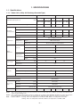
1-1-1. Indoor Unit (4-Way Air Discharge Cassette Type)
Model name
RAV-SM1100UT-E
Standard capacity (Note 1)
(kW)
Energy consumption effect ratio (Cooling)
Cooling
Heating
10.0
(2.2 – 11.2)
11.2
(2.2 – 13.0)
2.84
3.22
Power supply
Electrical
characteristics
Running current
Main unit
Outer
dimension
Ceiling panel
(Sold separately)
Heating
12.3
(3.0 – 13.2)
14.0
(3.0 – 16.0)
3.01
3.50
3.03
16.1–14.8
19.2–17.6
18.7–17.2
(kW)
3.52
3.48
4.09
4.00
(%)
98
98
97
97
Main unit
(Sold separately)
Cooling
16.3–15.0
(A)
Power consumption
Ceiling Panel
Average
Average
3.26
1 phase 230V (220 – 240V) 50Hz
Power factor
Appearance
RAV-SM1400UT-E
Zinc hot dipping steel plate
Model
RBC-U21PG (W)-E
Panel color
Moon-white (Muncel 2.5GY 9.0/0.5)
Height
(mm)
256
319
Width
(mm)
840
840
Depth
(mm)
840
840
Height
(mm)
35
Width
(mm)
950
Depth
(mm)
950
Main unit
22
(kg)
26
Total weight
Ceiling panel
4.5
Heat exchanger
Finned tubu
Fan
Fan unit
Turbo fan
Standard air flow High (Mid./Low)
Motor
(m³/h)
(W)
1680
1980
60
90
Air filter
Attached ceiling panel
Controller (Sold separately)
Connecting
pipe
Gas side
(mm)
Ø15.9 (5/8”)
Liquid side
(mm)
Ø9.5 (3/8”)
Drain port
Sound level
RBC-AMT21E
High (Mid./Low) (Note 2)
(Nominal dia.)
(dB•A)
25 (Polyvinyl chloride tube)
39
36
33
42
38
34
Note 1 : The cooling capacities and electrical characteristics are measured under the conditions speciied by JIS B 8616 based
on the reference piping 7.5m.
Note 2 : The sound level is measured in an anechoic chamber in accordance with JIS B8616. Normally, the values measured in
the actual operating environment become larger than the indicated values due to the effects of external sound.
Note : Rated conditions
Cooling : Indoor air temperature 27°C DB/19°C WB, Outdoor air temperature 35°C DB
Heating : Indoor air temperature 20°C DB, Outdoor air temperature 7°C DB/6°C WB
–3–
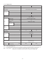
1-1-2. Outdoor Unit
Model name
RAV-SM1100AT-E
RAV-SM1400AT-E
Appearance
Silky shade (Muncel 1Y8.5/0.5)
Power supply
1 phase 230V (220 – 240V) 50Hz
(Power exclusive to outdoor is required.)
Type
Compressor
Hermetic compressor
Motor
(kW)
2.0
3.75
Pole
4 poles
Refrigerant charged
(kg)
R410A 2.1
Refrigerant control
Pulse motor valve
Standard length
20 (without additional charge)
Max. total length
Pipe
R410A 2.3
(m)
50
Over 20m
Add 40g/m (Max. 1200g)
Outdoor lower
(m)
15
Outdoor higher
(m)
30
Height difference
Outer
dimension
Height
(mm)
1340
Width
(mm)
900
Depth
(mm)
320
Total weight
(kg)
75
Heat exchanger
Finned tube
Fan
Fan unit
Standard air flow High
Motor
Connecting
pipe
2 propeller fans
(m³/h)
(W)
6800
7500
63 + 43
63 + 63
Gas side
(mm)
Ø15.9 (5/8”)
Liquid side
(mm)
Ø9.5 (3/8”)
Discharge temp. sensor
Over-current sensor
Compressor thermo.
Protection device
Sound level
(Note 2)
85
High (Mid./Low)
(Cooling/Heating)
53/54
(dB•A)
53/54
Note 1 : The cooling capacities and electrical characteristics are measured under the conditions speciied by JIS B 8616 based
on the reference piping 7.5m.
Note 2 : The sound level is measured in an anechoic chamber in accordance with JIS B8616. Normally, the values measured in
the actual operating environment become larger than the indicated values due to the effects of external sound.
Note : Rated conditions
Cooling : Indoor air temperature 27°C DB/19°C WB, Outdoor air temperature 35°C DB
Heating : Indoor air temperature 20°C DB, Outdoor air temperature 7°C DB/6°C WB
–4–
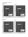
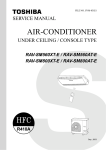
1-2. Operation Characteristic Curve
RAV-SM1100UT-E
<Cooling>
20
20
18
18
16
16
RAV-SM1100UT-E
14
12
10
8
6
12
10
8
6
• Conditions
Indoor : DB27˚C/WB19˚C
Outdoor : DB35˚C
Air flow : High
Pipe length : 7.5m
230V
4
2
0
RAV-SM1100UT-E
14
Current (A)
Current (A)
<Heating>
0
20
40
60
80
100
• Conditions
Indoor : DB20˚C
Outdoor : DB7˚C/WB6˚C
Air flow : High
Pipe length : 7.5m
230V
4
2
0
120
0
Compressor speed (rps)
22
20
20
18
18
RAV-SM1400UT-E
80
100
120
RAV-SM1400UT-E
16
14
Current (A)
14
Current (A)
60
<Heating>
22
12
10
8
12
10
8
6
6
• Conditions
Indoor : DB27˚C/WB19˚C
Outdoor : DB35˚C
Air flow : High
Pipe length : 7.5m
230V
4
2
0
40
Compressor speed (rps)
RAV-SM1400UT-E
<Cooling>
16
20
0
20
40
60
• Conditions
Indoor : DB20˚C
Outdoor : DB7˚C/WB6˚C
Air flow : High
Pipe length : 7.5m
230V
4
2
0
80
Compressor speed (rps)
0
20
40
60
Compressor speed (rps)
–5–
80
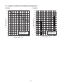
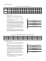
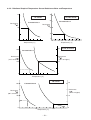
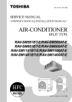
1-3. Capacity variation ratio according to temperature
<Cooling>
<Heating>
105
120
100
110
95
100
90
Capacity ratio (%)
Capacity ratio (%)
90
85
80
75
70
65
60
55
80
70
60
50
40
30
20
• Conditions
Indoor : DB27˚C/WB19˚C
Indoor air flow : High
Pipe length : 7.5m
• Conditions
Indoor : DB20˚C
Indoor air flow : High
Pipe length : 7.5m
10
0
50
32 33 34 35 36 37 38 39 40 41 42 43
-14 -12 -10 -8 -6 -4 -2
0
2
Outsoor temp. (˚C)
Outsoor temp. (˚C)
–6–
4
6
8
10
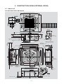
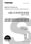
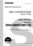
2. CONSTRUCTION VIEWS (EXTERNAL VIEWS)
2-1. Indoor Unit
RAV-SM1100UT-E/RAV-SM1400UT-E
860 to 910 Recommended external size
860 to 910 Recommended external size
200
200
Check port
(¨450)
Check port
(¨450)
B
A
C
D
SM1100UT Ø12.7 Ø15.9 120
256
SM1400UT Ø12.7 Ø15.9 183
319
30
130
210
105
173
A
Refrigerant pipe connecting port
B
Indoor unit
270
70
Knockout square hole
for divide duct
For Ø150
250
130
Drain up standing size
Hanging bolt
M10 or Ø3/8
(To be procured locally)
860 to 910 Ceiling opening dimension
Ceiling
bottom
surface
Surface
under ceiling
Drain pipe
connecting port
105
Refrigerant pipe connecting port
Standing
640 or less
Ceiling bottom surface
113
Take-in port of pipes
360
45
Standing
850 or less
950 Panel external dimension
D
790 Hanging bolt pitch
Electric parts box
88
345.5
227
480
950 Panel external dimension
Ceiling panel
(sold separately)
35˚
860 to 910 Ceiling opening dimension
381.6
434.5
723 Hanging bolt pitch
105
240
105
840 Unit external dimension
105
80
Ø162
105
Ø162
C
97
254.5
57
840 Unit external dimension
35
64
Knockout square
hole for divide duct
for Ø150
(2 positions)
480
.5
57
Ceiling bottom
surface
25
C
227
Z view
97
8
18
Surface under ceiling
Ceiling bottom surface
–7–
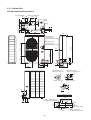
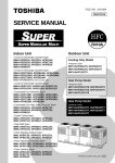
2-2. Outdoor Unit
RAV-SM1100AT-E/RAV-SM1400AT-E
40
43
21
60
50
B legs
A legs
Suction
Knockout(Drain)
port
26
Drain hole (Ø25)
Discharge port
600
43
40
54
21
Suction
port
108
320
900
Refrigerant pipe
connecting port
(Ø9.5 flare at liquid side)
1340
Refrigerant pipe
connecting port
(Ø15.9 flare at gas side)
67
154
60 90
350
89
25
706
715
625
28
314
60
27
95
307
27
58
161
400
60
z
Mountig bolt hole
(Ø12 x 17 long hole)
40
40
20
Mountig bolt hole
(Ø12 x 17 U-shape hole)
12
Details of A legs
Details of B legs
58
7
86 7
46
80
Z view
Space required for service
165
45
365
32
2-Ø12 x 17 U-shape holes
(For Ø8–Ø10 anchor bolt)
150
or more
600
60
365
17.5
Drain hole (Ø20 x 88)
191
20
40
90
70
17.5
Knockout(Drain)
29
Suction port
150
or more
150
or more
Discharge (Minimum
port
distance up to wall)
500
Discharge 2-Ø12 x 17 long hole
or more
port
–8–
(For Ø8–Ø10 anchor bolt)
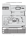
3. SYSTEMATIC REFRIGERATING CYCLE DIAGRAM
3-1. Indoor Unit/Outdoor Unit
RAV-SM1100UT-E/RAV-SM1100AT-E
Indoor unit
Distributor
(Strainer incorporated)
TCJ sensor
Outer diameter of refrigerant pipe
Gas side ØA
Liquid side ØB
15.9mm
9.5mm
Strainer
Air heat exchanger
TC sensor
Refrigerant pipe
at gas side
Outer dia. ØA
Refrigerant pipe
at liquid side
Outer dia. ØB
Max.
50m
Ball valve
Outer dia. ØA
Strainer
Check joint
TS sensor
Packed valve
Outer dia. ØB
Outdoor unit
PMV
(UKV-25D22)
TO sensor
TD sensor
Strainer
TE sensor
4-way valve
(STF-0213Z)
Heat exchanger Ø8
1 row 52 stages
FP1.3 flat fin
Muffler
Distributor
Ø25 × L210
Ø25 × L180
Accumulator
Rotary
(2500cc) compressor
(DA220A2F – 20L)
R410A 2.1kg
Cooling
Heating
Pipe surface temperature (°C)
Pressure
(MPa)
Cooling
Heating
Discharge
Suction
Compressor
Indoor heat Outdoor heat revolutions per
exchanger
exchanger
second (rps)
(TC)
(TE)
*
10
8
38
92
14
14
46
74
8
8
3
4
50
2
Pd
Ps
(TD)
(TS)
Standard
3.3
0.9
88
Overload
3.0
1.0
88
Low load
1.0
0.8
30
Standard
2.5
0.6
90
Overload
3.3
1.1
83
17
54
Low load
1.8
0.2
80
–23
29
13
–20
Indoor
fan
Indoor/Outdoor
temp. conditions
(DB/WB) (°C)
Indoor
Outdoor
HIGH
27/19
35/–
HIGH
32/24
43/–
27
LOW
18/15.5
–5/–
86
HIGH
20/–
7/6
52
LOW
30.–
24/18
100
HIGH
15/–
–20/ (70%)
* 4 poles are provided to this compressor.
The compressor frequency (Hz) measured with a clamp meter is 2 times of revolutions (rps) of the compressor.
–9 –
RAV-SM1400UT-E/RAV-SM1400AT-E
Indoor unit
Distributor
(Strainer incorporated)
TCJ sensor
Outer diameter of refrigerant pipe
Gas side ØA
Liquid side ØB
15.9mm
9.5mm
Strainer
Air heat exchanger
TC sensor
Refrigerant pipe
at gas side
Outer dia. ØA
Refrigerant pipe
at liquid side
Outer dia. ØB
Max.
50m
Ball valve
Outer dia. ØA
Strainer
Check joint
TS sensor
Packed valve
Outer dia. ØB
Outdoor unit
PMV
(UKV-25D22)
TO sensor
TD sensor
Strainer
TE sensor
4-way valve
(STF-0213Z)
Heat exchanger Ø8
1 row 52 stages
FP1.3 flat fin
Muffler
Distributor
Ø25 × L210
Ø25 × L180
Accumulator
Rotary
(2500cc) compressor
(DA420A3F – 21M)
R410A 2.3kg
Cooling
Heating
Pipe surface temperature (°C)
Pressure
(MPa)
Cooling
Heating
Discharge
Suction
Compressor
Indoor heat Outdoor heat revolutions per
exchanger
exchanger
second (rps)
Pd
Ps
(TD)
(TS)
(TC)
(TE)
*
Standard
3.3
0.9
84
11
10
40
56
Overload
3.5
1.0
87
7
15
54
54
Low load
1.7
0.8
44
8
4
8
Standard
3.0
0.6
79
2
44
2
Overload
3.4
1.1
78
21
54
17
Low load
2.0
0.2
82
–21
36
–18
Indoor
fan
Indoor/Outdoor
temp. conditions
(DB/WB) (°C)
Indoor
Outdoor
HIGH
27/19
35/–
HIGH
32/24
43/–
27
LOW
18/15.5
–5/–
60
HIGH
20/–
7/6
24
LOW
30.–
24/18
73
HIGH
15/–
–20/ (70%)
* 4 poles are provided to this compressor.
The compressor frequency (Hz) measured with a clamp meter is 2 times of revolutions (rps) of the compressor.
–10 –
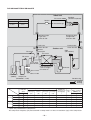
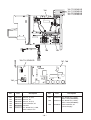
4. WIRING DIAGRAM
4-1. Indoor Unit
RAV-SM1100UT-E/RAV-SM1400UT-E
TA
FS
CN34
(RED)
3 3
2 2
1 1
LM1
5
4
3
2
1
1 2
1 2
1 2
1 2
CN104
(YEL)
CN102
(RED)
LM2
5
4
3
2
1
5
4
3
2
1
5
4
3
2
1
1
1
2
2
(EXCT)
CN101
(BLK)
1 2 3
1 2
CN80
(GRN)
CN73
(RED)
1
2
CN70
(WHI)
2 CN32
1 (WHI)
DC20V
DC15V
DC12V
DC7V
(FAN DRIVE)
6
5
4 CN61
3 (YEL)
2
1
Power
supply
circuit
Fuse
F302
T3.15A
250V~
CN333
(WHI)
5
4
3
2
1
5
4
3
2
1
1
2
3
4
5
5
4 CN50
3 (WHI)
2
1
Motor
drive
circuit
Motor
drive
circuit
CN334
(WHI)
1
2
3
4
5
5
4 CN620
3 (BLU)
2
1
6
5
4 CN60
3 (WHI)
2
1
Control P.C. Board for
Indoor Unit
5
4
3
2
1
5
4
3
2
1
FM
TC
MCC-1402
5
4
3
2
1
CN33
(WHI)
5
4
3
2
1
TCJ
CN68 1 2 3
(BLU) 1 2 3
RY
303
1 2 3
CN304
(GRY)
2 2 CN001
1 1 (WHI)
WHI
3
2 CN309
(YEL)
1
BLK
RY
302
BLK
3 3
2 2
BLK
1 1
Fuse
F301
250V~
T6.3A
P301
CN67 1 2 3 4 5
(BLK) 1 2 3 4 5
BLK 1 2
CN66
(WHI)
CN41
(BLU)
Adapter for
Wireless Remote
Controller
B
A
BLK
2 2 CN1
1 1 (WHI)
WHI
Wired Renote
Controller
RED WHI BLK
RED
DP
Closed-end
connector
WHI
1 2 3
Indoor unit
earth screw
NOTE
FM
TA
TC
TCJ
LM1,LM2
DP
FS
RY302
: Fan motor
: Indoor temp. sensor
: Temp. sensor
: Temp. sensor
: Louver motor
: Drain pump motor
: Float switch
: Drain control relay
1 2 3
Serial
signal
Single phase
220 to 240V
50Hz
L N
– 11 –
Outdoor unit
earth screw
Color
Identification
BLK
BLU
RED
GRY
PNK
GRN
WHI
BRW
ORN
YEL
:
:
:
:
:
:
:
:
:
:
BLACK
BLUE
RED
GRAY
PINK
GREEN
WHITE
BROWN
ORANGE
YELLOW
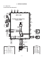
4-2. Outdoor Unit
RAV-SM1100AT-E/RAV-SM1400AT-E
Color Identification
COMPRESSOR
BLK
BLU
RED
GRY
PNK
GRN
RED
WHI
CM
BLK
TH
CN09 CN10 CN11
2 2 CN600
1 1
TO
2 2
CN601
1 1
IGBT MODULE
TE
2 2
CN604
1 1
TS
3 3
2 2 CN605
1 1
TD
3 3
2 2 CN600
1 1
BLU
P18
SWITCHING
REGURATOR
F04
250V~
FUSE T3.15A
P17
YEL
P20
P19
:
:
:
:
:
:
BLACK
BLUE
RED
GRAY
PINK
GREEN
CN606
2
1
ORN
2 2
1 1 ORN
CN500
250V~
BLU
3 3
3 3
2 2
2 2 T5A
YEL
1 1
1 1
CN04 CN03 FUSE
F300
RY01
+ ~
~
~–
BLK P29
P28
BRN
P24
REACTOR
P13
3 3
GRY
2 2
1 1 GRY
P12
+
–
~
~
FUN
CIRCUIT
SUB P.C. BOARD
(MCC-1398)
F02
FUSE
250V~
T25A
SERIAL
COMMUNICATION
CIRCUIT
P09
3 3
WHI
2 2
1 1 WHI
P08 T02 CT
CN301
3 3
2 2
1 1
FM01 FAN MOTOR
CN302
5 5
4 4
3 3
2 2
1 1
2 2
2 2
ORN
1 1
1 1
CN05 CN04
P21
REACTOR
FUN
CIRCUIT
P.C. BOARD
(MCC-1438)
ORN
THERMOSTAT
CN300
5 5
4 4
3 3
2 2
1 1
BLK
5 5
5 5
WHI
4 4
4 4
BLU
3 3
3 3
RED
2 2
2 2
PNK
1 1
1 1
CN06 CN800
RED
WHI : WHITE
BRN : BROWN
ORN : ORANGE
YEL : YELLOW
PUR : PURPLE
GRN/YEL : GREEN&YELLOW
CN303
3 3
2 2
1 1
CN702
6 6
5 5
4 4
3 3
2 2
1 1
FM02 FAN MOTOR
PMV
BLK
5 5
5 5 T3.15A
4 4
4 4
WHI
250V~
3 3
3 3
2 2
2 2 F01 FUSE
1 1 RED 1 1
CN13 CN01
RY700
1 2 3 1 2 3
CN700 1 2 3 1 2 3 CN02
GRY
4-WAY
VALVE
WHI
GRN/YEL
WHI
T25A
250V~
F01
FUSE
RED
CN01
CN02
CN03
L
BLK
WHI
RED
– 12 –
N
POWER SUPPLY
220-240V~
50Hz
1
WHI
2
TO INDOOR UNIT
GRY
3
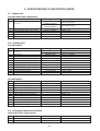
5. SPECIFICATIONS OF ELECTRICAL PARTS
5-1. Indoor Unit
RAV-SM1100UT-E/RAV-SM1400UT-E
No.
1
2
3
4
5
6
Parts name
Fan motor
Thermo. sensor (TA-sensor)
Heat exchanger sensor (TCJ-sensor)
Heat exchanger sensor (TC-sensor)
Float switch
Drain pump motor
Type
SWF-230-60-1
(RAV-SM1100UT-E)
SWF-230-90-1
(RAV-SM1400UT-E)
155 mm
Ø6 mm, 1200 mm
Ø6 mm, 1200 mm
FS-0218-102
ADP-1409
Specifications
Output (Rated) 60 W
Output (Rated) 90 W
10 kΩ at 25°C
10 kΩ at 25°C
10 kΩ at 25°C
5-2. Outdoor Unit
RAV-SM1100AT-E
Parts name
No.
1
Fan motor
2
3
4
5
6
7
8
9
10
11
Compressor
Reactor
Outdoor temp. sensor (To-sensor)
Heat exchanger sensor (Te-sensor)
Suction temp. sensor (Ts-sensor)
Discharge temp. sensor (Td-sensor)
Fuse (Switching power (Protect))
Fuse (Inverter, input (Current protect)
4-way valve solenoid coil
Compressor thermo. (Protection)
Type
ICF-140-63-2
ICF-140-43-2
DA220A2F-20L
CH-56
—
—
—
—
VHV-01AJ502E1
US-622
Specifications
Output (Rated) 63 W
Output (Rated) 43 W
3 phase, 4P, 2000 W
6 mH, 18.5 A
10 kΩ at 25°C
10 kΩ at 25°C
10 kΩ at 25°C
50 kΩ at 25°C
T3.15 A, AC 250 V
25 A, AC 250 V
AC 220 – 240 V
ON : 90 ± 5°C, OFF : 125 ± 4°C
RAV-SM1400AT-E
No.
1
2
3
4
5
6
7
8
9
10
11
Parts name
Fan motor
Compressor
Reactor
Outdoor temp. sensor (To-sensor)
Heat exchanger sensor (Te-sensor)
Suction temp. sensor (Ts-sensor)
Discharge temp. sensor (Td-sensor)
Fuse (Switching power (Protect))
Fuse (Inverter, input (Current protect))
4-way valve solenoid coil
Compressor thermo. (Protection)
Type
ICF-140-63-2
DA420A3F-21M
CH-56
—
—
—
—
VHV-01AJ502E1
US-622
Specifications
Output (Rated) 63 W
3 phase, 4P, 3500 W
6 mH, 18.5 A
10 kΩ at 25°C
10 kΩ at 25°C
10 kΩ at 25°C
50 kΩ at 25°C
T3.15 A, AC 250 V
25 A, AC 250 V
AC 220 – 240 V
ON : 90 ± 5°C, OFF : 125 ± 4°C
5-3. Accessory Separate Sold Parts
RBC-U21PG (W) E (Ceiling panel)
No.
1
2
Parts name
Motor-louver
Type
MP24GA
– 13 –
Specifications
DC 12 V
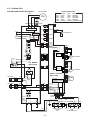
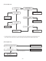
6. INDOOR CONTROL
6-1. Indoor Control Circuit
Weekly timer
Main (Sub) master remote controller
Display
LCD
Max. 8 units are connectable.*1
CPU
Display
LED
*1 Max. 7 units when network adapters
are attached
LCD
driver
Display
LCD
Function setup
Function setup
CPU
Key switch
Key sw i tc h
*2 Network adapters are attached to only
one unit.
*3 Weekly timer is not connectable to the
sub remote controller.
CN2 CN1
DC5V
*3
Remote
controller
communication
circuit
DC5V
Power
circuit
Power circuit
Central control
remote controller
(Option)
Secondary
battery
Option
Option
Indoor unit
#1
A
#2
B
A
B
#3
A
B
Network adapter (Option)
Network adapter
P.C. board
Remote
(MCC-1401) controller
communication
circuit
X
Y
Indoor control P.C. board (MCC-1402)
Remote
controller
communication
circuit
DC20V
EEPROM
DC12V
AI NET
communication
circuit
CPU
H8/3687
DC5V
TA sensor
Humidifier
relay output
DC5V
Power circuit Switch setup
Driver
Heater relay
output
CPU
H8/3039
TC sensor
TCJ sensor
Same as
the left
*2
Same as
the left
*2
Transformer
Float input
Louver
motor
CPU
TMP88CH
47FG
(TMP88PH
47FG)
Drain
pump
Indoor
fan
motor
Power
circuit
Fan motor
control
circuit
Outside
output
Run
Warning
Ready
Thermo. ON
Cool
Heat
Fan
AC
synchronous
signal input
circuit
Serial
send/
receive
circuit
1 2 3
1 2 3
DC280V
Outdoor
unit
Wireless remote controller kit
1 2 3
1 2 3
Sensor P.C. board (MCC-1418)
Power
circuit
DC5V
Outdoor unit
Buzzer
Optional only for 4-way air
discharge cassette type models
– 14 –
Remote
controller
communication
circuit
CPU
Receive circuit
Temporary
operation SW
Function
setup SW
Display LED
Outdoor
unit
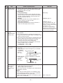
6-2. Control Specifications
No.
1
2
Item
When power
supply is reset
Operation mode
selection
Outline of specifications
1) Distinction of outdoor units
When the power supply is reset, the outdoors are
distinguished, and control is exchanged according to
the distinguished result.
2) Setting of speed of the indoor fan/setting whether to
adjust air direction or not.
(Only 4-way models)
Based on EEPROM data, speed of the indoor fan or
setting whether to adjust air direction or not is selected.
Remarks
Air speed/
Air direction adjustment
1) Based on the operation mode selecting command
from the remote controller, the operation mode is
selected.
Remote controller
command
STOP
FAN
COOL
Outline of control
Air conditioner stops.
Fan operation
Cooling operation
DRY
Dry operation
HEAT
Heating operation
AUTO
• COOL/HEAT operation mode
is automatically selected by Ta
and Ts for operation.
Ta
(˚C)
COOL
+1.5
(COOL ON)
Tsc
or Tsh
(COOL OFF)
-1.5
HEAT
1) Judge the selection of COOL/HEAT mode as shown
in the figure above.
When 10 minutes passed after thermostat had
been turned off, the heating operation (Thermo
OFF) is exchanged to cooling operation if Tsh
exceeds +1.5 or more.
(COOL OFF) and (COOL ON) in the figure indicate
an example.
When 10 minutes passed after thermostat had
been turned off, the cooling operation (Thermo
OFF) is exchanged to heating operation if Tsc
exceeds –1.5 or less.
2) For the automatic capacity control after judgment of
COOL/HEAT, refer to item 4.
3) For the temperature correction of room temperature
control in automatic heating operation, refer to item 3.
– 15 –
Ta : Room temperature
Ts : Setup temperature
Tsc : Setup temperature in
cooling operation
Tsh : Setup temperature
+ Room temperature
control temperature
compensation
No.
3
Item
Room
temperature
control
Outline of specifications
Remarks
1) Adjustment range Remote controller setup temperature (°C)
COOL/
DRY
Heating
operation
Auto
operation
Wired type
18 to 29
18 to 29
18 to 29
Wireless type*
18 to 30
16 to 30
17 to 27
* : Only for 4-way air discharge cassette type
2) Using the item code 06, the setup temperature in
heating operation can be compensated.
Setup data
Setup temp.
compensation
0
2
4
6
+0°C
+2°C
+4°C
+6°C
Shift of suction temperature in heating operation
Setting at shipment
Setup data
2
4
Automatic
capacity control
(GA control)
1) Based on the difference between Ta and Ts, the
operation frequency is instructed to the outdoor unit.
5
Air speed
selection
1) Operation with (HH), (H), (L), or [AUTO] mode is
HH > H > L > LL
performed by the command from the remote controller.
2) When the air speed mode [AUTO] is selected, the air
speed varies by the difference between Ta and Ts.
<COOL>
Ta (˚C)
+3.0
+2.5
+2.0
+1.5
+1.0
+0.5
Tsc
-0.5
A
B
C
D
HH
(HH)
H (HH)
H (HH)
L(H)
E
L(H)
L(H)
L(L)
F
G
• Controlling operation in case when thermo of remote
controller works is same as a case when thermo of
the body works.
• If the air speed has been changed once, it is not
changed for 3 minutes. However when the air volume
is exchanged, the air speed changes.
• When cooling operation has started, the air speed
selects a downward slope, that is, the high position.
• If the temperature is just on the difference boundary,
the air speed does not change.
• Mode in the parentheses indicates one in automatic
cooling operation.
– 16 –
No.
5
Item
Air speed
selection
(Continued)
Outline of specifications
Remarks
<HEAT>
Ta (˚C)
L(L)
L(H)
H(H)
(-0.5) –1.0
(0)
Tsh
(+0.5) +1.0
(+1.0) +2.0
(+1.5) +3.0
E
H
(HH)
D
HH
(HH)
C
B
(+2.0) +4.0
A
Value in the parentheses indicates one when thermostat of
the remote controller works.
Value without parentheses indicates one when thermostat
of the body works.
• If the air speed has been changed once, it is not
changed for 1 minute. However when the air speed is
exchanged, the air speed changes.
• When heating operation has started, the air speed
selects a upward slope, that is, the high position.
• If the temperature is just on the difference boundary, the
air speed does not change.
• Mode in the parentheses indicates one in automatic
heating operation.
• In Tc ≥ 60°C, the air speed increases by 1 step.
<Operation of duct only>
Air volume setup
Tap
COOL, DRY, FAN
SM1100 SM1400
HEAT
Revolutions per
minute (rpm)
F4
UH
530
660
F5
H
510
660
500
620
M+
470
570
M
450
520
440
510
L+
410
470
L
390
430
380
420
320
370
F6
H
F7
M+
F8
F9
M
FA
FB
L+
FC
L
FD
UL
3) In heating operation, the mode changes to [UL] if
thermostat is turned off.
4) If Ta ≥ 25°C when heating operation has started and
when defrost operation has been cleared, it operates
with HIGH (H) mode or (HH) for 1 minute from when Tc
has entered in E zone of cool air discharge preventive
control (Item 6).
5) In automatic cooling/heating operation, the revolution
frequency of [HH] is set larger than that in the standard
cooling/heating operation. However the revolution
frequency is restricted in the automatic heating operation as shown in the following figure.
–17 –
Tc: Indoor heat exchanger
sensor temperature
[PRE-HEAT] display
Tc
(˚C)
47
F5
42
F5
F4
No.
6
Item
Cool air
discharge
preventive
control
Outline of specifications
Remarks
1) In heating operation, the indoor fan is controlled based
on the detected temperature of Tc sensor or Tcj sensor.
As shown below, the
Tc (˚C)
Tcj
upper limit of the
HH
32
revolution frequency
H
30 L
is determined.
E zone
In D or E zone, the priority
is given to setup of air
volume exchange.
In A and B zones,
[PRE-HEAT] is displayed.
28
UL
D zone
26
20
16
7
OFF
C zone
B zone
A zone
Freeze preven- 1) The cooling operation (including Dry operation) is
Tcj : Indoor heat extive control
performed as follows based on the detected temperachanger sensor
(Low temperature of Tc sensor or Tcj sensor.
temperature
ture release)
When [J] zone is detected for 6 minutes (Following
figure), the commanded frequency is decreased from
the real operation frequency. After then the commanded
frequency changes every 30 seconds while operation is
performed in [J] zone.
In [K] zone, time counting is interrupted and the operation is held.
When [I] zone is detected, the timer is cleared and the
operation returns to the normal operation.
If the commanded frequency becomes S0 because the
operation continues in [J] zone, the return temperature
A is raised from 5°C to 12°C until [I] zone is detected
and the indoor fan
(˚C)
operates with [M] mode.
5
A
I
K
2
J
In heating operation, the freeze-preventive control
works if 4-way valve is not exchanged and the condition
is satisfied. (However the temperature for J zone
dashing control is changed from 2°C to –5°C.)
8
High-temp
release control
1) The heating operation is performed as follows based on
the detected temperature of Tc sensor or Tcj sensor.
• When [M] zone is detected, the commanded frequency is decreased from the real operation frequency. After then the commanded frequency
changes every 30 seconds while operation is performed in [M] zone.
• In [N] zone, the commanded frequency is held.
• When [L] zone is detected, the commanded frequency is returned to the original value by approx.
6Hz every 60 seconds.
Setup at
shipment
Control temp (°C)
A
B
56 (54)
52 (52)
Tc (˚C)
Tcj A
M
N
B
L
NOTE :
When the operation has started or when Tc or Tcj became
lower than 30°C after start of the operation, temperature is
controlled between values in parentheses of A and B.
– 18 –
Same when thermostat is
turned off.
No.
Item
Outline of specifications
9
Drain pump control
1) In cooling operation (including Dry operation), the
drain pump is usually operated.
2) If the float switch operates while drain pump
operates, the compressor stops, the drain pump
continues the operation, and a check code is
output.
3) If the float switch operates while drain pump stops,
the compressor stops and the drain pump operates. If the float switch keeps operating for approx.
4 minutes, a check code is output.
(For the duct, when
the drain-up kit
(sold separately) is
mounted)
10
After-heat elimination
When heating operation stops, the indoor fan operates
with LOW mode for approx. 30 seconds.
11
Flap control
1) Flap position setup
• When the flap position is changed, the position
moves necessarily to downward discharge
position once to return to the set position.
• The flap position can be set up in the following
operation range.
(For 4-way air
discharge cassette
type only)
Remarks
Check code [P10]
In cooling/dry operation In heating/fan operation
• In group twin/triple operation, the flap positions
can be set up collectively or individually.
2) Swing setup
• The swinging position can be moved in the
following operation range.
All modes
• In group twin/triple operation, the swinging
positions can be set up collectively or individually.
3) When the unit stops or when a warning is output,
the flap automatically moves downward.
4) While the heating operation is ready, the flap
automatically moves upward.
– 19 –
Warning :
A check code is displayed
on the remote controller,
and the indoor unit stops.
(Excluding [F08] and
[L31])
No.
12
Item
Frequency fixed
operation
(Test run)
Outline of specifications
Remarks
<In case of wired remote controller>
1. When pushing [CHECK] button for 4 seconds or more,
[TEST] is displayed on the display screen and the
mode enters in Test run mode.
2. Push [ON/OFF] button.
3. Using [MODE] button, change the mode from [COOL]
to [HEAT].
• Do not use other mode than [COOL]/[HEAT] mode.
• During test run operation, the temperature cannot be
adjusted.
• An error is detected as usual.
• A frequency fixed operation is performed.
4. After the test run, push [ON/OFF] button to stop the
operation. (Display in the display part is same as the
procedure in item 1).)
5. Push [CHECK] button to clear the test run mode.
([TEST] display in the display part disappears and the
status returns to the normal stop status.)
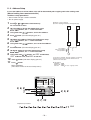
<In case of wireless remote controller>
(Option for 4-way air discharge cassette type only)
1. Turn off the power of the set.
Remove the adjuster with sensors from the ceiling
panel.
2. Turn Bit [1: TEST] of sensor P.C. board switch [S003]
from OFF to ON.
Attach the sensor P.C. board cover and mount the
adjuster with sensors to the ceiling panel.
Turn on the power of the set.
3. Push [ON/OFF] button of the wireless remote controller
and set the operation mode to [COOL] or [HEAT] using
[MODE] button.
(During test run operation, all the display lamps of
wireless remote controller sensors flash.)
• Do not use other mode than [COOL]/[HEAT] mode.
• An error is detected as usual.
• A frequency fixed operation is performed.
4. After the test run, push [ON/OFF] button to stop the
operation.
5. Turn off the power of the set.
Turn Bit [1: TEST] of sensor P.C. board switch [S003]
from ON to OFF.
Mount the adjuster with sensors to the ceiling panel.
13
Filter sign display
(Except wireless
type)
1) The operation time of the indoor fan is calculated, the
filter reset signal is sent to the remote controller when
the specified time (2500H) has passed, and it is
displayed on LCD.
2) When the filter reset signal has been received from the
remote controller, time of the calculation timer is
cleared. In this case, the measurement time is reset if
the specified time has passed, and display on LCD
disappears.
– 20 –
[FILTER] goes on.
No.
14
15
Item
Central control
mode selection
Outline of specifications
1) Setting at the central controller side enables to select
the contents which can be operated on the remote
controller at indoor unit side.
2) RBC-AMT21
[Last push priority] :
The operation contents can be selected from both
remote controller and central controller of the indoor
unit side, and the operation is performed with the
contents selected at the last.
[Center] :
Start/Stop operation only can be handled on the
remote controller at indoor unit side.
[Operation Prohibited] :
It cannot be operated on the remote controller at
indoor unit side. (Stop status is held.)
Energy-save
control
(By connected
outdoor unit)
1) Selecting [AUTO] mode enables an energy-saving to
be operated.
2) The setup temperature is shifted (corrected) in the
range not to lose the comfort ability according to input
values of various sensors.
3) Data (Input value room temp. Ta, Outside temp. To, Air
volume, Indoor heat exchanger sensor temp. Tc) for
20 minutes are taken the average to calculate
correction value of the setup temperature.
4) The setup temperature is shifted every 20 minutes,
and the shifted range is as follows.
In cooling time : +1.5 to –1.0K
In heating time : –1.5 to +1.0K
Max. frequency
cut control
1) This control is operated by selecting [AUTO] operation mode.
2) COOL operation mode: the frequency is controlled
according to
Ta(˚C) Normal control
the following
+4
figure if
Max. frequency is restricted
To < 28°C.
+3
to approximately the rated
Remarks
(No display)
[CENTER] goes on.
[CENTER] goes on.
In a case of wireless type, the
display lamp does not change.
However, contents which can be
operated are same.
The status set in [CENTER]/
[Operation Prohibited] mode is
notified with the receiving sound
“Pi, Pi, Pi, Pi, Pi” (5 times).
cooling frequency
Tsc
3) HEAT operation mode: the frequency is controlled
according to
Ta(˚C)
the right
Tsh
Max. frequency is restricted
figure if
to approximately the rated
To > 15°C.
heating frequency
–3
–4
DC motor
(For 4-way air
discharge
cassette type
only)
Normal control
1) When the fan operation has started, positioning of the
stator and the rotor are performed.
(Moves slightly with tap sound)
2) The motor operates according to the command from
the indoor controller.
NOTES :
• When the fan rotates while the air conditioner stops
due to entering of outside air, etc, the air conditioner
may operated while the fan motor stops.
• When a fan locking is found, the air conditioner stops,
Check code [P12]
and an error is displayed.
–21 –
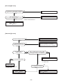
Louver
Optional output
– 22 –
Remote controller power LED
Network adapter Indoor/Outdoor
power supply
inter-unit cable
Remote controller inter-unit cable
Outside error input
TC sensor
TCJ sensor
TA sensor
DISP
CHK
EXCT
EEPROM
Drain pump
output
RAV-SM1100UT-E/RAV-SM1400UT-E
<MCC-1402>
Float SW
DC fan return
DC fan output
Microcomputer operation LED
6-3. Indoor Print Circuit Board
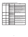
6-4. Indoor P.C. Board Optional Connector Specifications
Function
Option output
Outside error
input
Filter option
error
CHK
Operation check
DISP display
mode
EXCT demand
Connector
No.
CN60
CN80
CN70
CN71
CN72
CN73
Pin
No.
Specifications
Remarks
1
DC12V (COM)
2
Defrost output
ON during defrost operation of outdoor unit
3
Thermo. ON output
ON during Real thermo-ON (Comp ON)
4
Cooling output
ON when operation mode is in cooling system
(COOL, DRY, COOL in AUTO cooling/heating)
5
Heating output
ON when operation mode is in heating system
(HEAT, HEAT in AUTO cooling/heating)
6
Fan output
ON during indoor fan ON
(Air purifier is used/Interlock cable)
1
DC12V (COM)
(When continued for 1 minute)
Check code “L30” is output and forced operation stops.
2
DC12V (COM)
3
Outside error input
1
Filter/Option/Humidifier
setup input
Option error input is controlled. (Protective operation
for device attached to outside is displayed.)
2
0V
* Setting of option error input is performed from
remote controller. (DN=2A)
1
Check mode input
2
0V
Used for operation check of indoor unit. (Communication with outdoor unit or remote controller is not
performed, but the specified operation such as indoor
fan “H” or drain pump ON is output.)
1
Display mode input
2
0V
1
Demand input
2
0V
Display mode enables indoor unit and remote controller to communicate. (When power is turned on)
Forced thermo-OFF operation in indoor unit
– 23 –
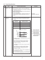
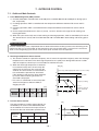
7. OUTDOOR CONTROL
7-1. Outline of Main Controls
1. Pulse Modulating Valve (PMV) control
1) For PMV, SM1100 is controlled with 45 to 500 pulses and SM1400 with 50 to 500 pulses during operation, respectively.
2) In cooling operation, PMV is controlled with the temperature difference between TS sensor and TC
sensor.
3) In heating operation, PMV is controlled with the temperature difference between TS sensor and TE
sensor.
4) For the temperature difference in items 2) and 3), 1 to 5K is aimed as the target in both cooling and
heating operations.
5) When the cycle excessively rose in both cooling and heating operations, PMV is controlled by TD sensor.
The aimed value is usually 105°C for SM1100 and 100°C for SM1400 in both cooling and heating operations.
REQUIREMENT
A sensor trouble may cause a liquid back-flow or abnormal overheat resulting in excessive shortening of the
compressor life. In a case of trouble on the compressor, be sure to check there is no error in the resistance
value an the refrigerating cycle of each sensor after repair and then start the operation.
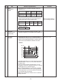
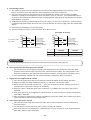
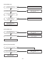
2. Discharge temperature release control
1) This function controls the operation frequency, that is, lowers the operation frequency when the discharge
temperature has not lower or the discharge temperature has rapidly risen during PMV control. It subdivides the frequency control up to a unit of 0.6Hz to stabilize the cycle.
2) When the discharge temperature is detected
in an abnormal stop zone, the unit stops the
compressor and restarts after 2 minutes 30
seconds. The error counter is cleared when it
has continued the operation for 10 minutes.
If the abnormal stop zone has been detected
by 4 times without clearing of counter, an
error ‘P03’ is displayed.
* The cause is considered as excessively little
amount of refrigerant, defective PMV, or
clogging of cycle.
TD [˚C]
Error stop ("P03" display with 4 times of error counts)
a
Frequency down
b
c
Frequency holding
d
[°C]
SM1100
SM1400
a
b
c
d
e
111
106
100
95
90
Frequency slow-up
(Up to command)
e
As command is
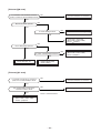
3. Current release control
The output frequency and the output voltage are
controlled by AC current value detected by T02
on the outdoor P.C. board so that input current of
the inverter does not exceed the specified value.
SM1100
[A]
Frequency down
I1
SM1400
Objective
model
COOL
HEAT
COOL
HEAT
I1 value [A]
18.90
19.65
19.65
19.65
1–0.5
–24 –
Hold
Hold
Normal operation
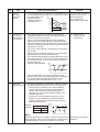
4. Outdoor fan control
Allocautions of fan tap revolutions [rpm]
SM1100
SM1400
W1
W2
W3
W4
W5
W6
W7
W8
W9
WA
WB
WC
WD
WE
Upper fan
250
280
300
320
340
380
420
470
520
570
630
690
740
800
Lower fan
OFF
OFF
270
290
400
480
520
560
600
660
720
780
860
940
Upper fan
250
270
270
300
350
410
470
530
590
670
750
810
840
860
Lower fan
OFF
OFF
240
270
330
390
450
510
570
650
730
790
820
840
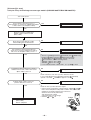
1) Cooling fan control
Q The outdoor fan is controlled by TE sensor.
(Cooling: Temperature conditions after medium
term)
The cooling fan is controlled by every 1 tap of DC
fan control (14 taps).
R At the activation time, although the maximum fan
tap in the following table are fixed for 60 seconds,
after then the fan may not rotate with high speed
for several minutes because the fan is controlled
by TE sensor value. It is not an abnormal status.
S When the discharge temperature sensor is
abnormal or the sensor comes off the holder, the
fan does not rotate with high speed, but a protective device works.
T When the outdoor fan does not rotate with high
speed, judge a fan error by comparing the control
data in the following table with TO and TE values.
TE [˚C]
MAX.
46
+30 rpm / 20 sec.
37
Hold zone
34
–30 rpm / 20 sec.
20
MIN.
Control for fan tap by outdoor temperature in normal operation
5 ≤ TO <10°C 10 ≤ TO < 15°C 15 ≤ TO < 20°C 20 ≤ TO < 25°C
TO
TO < 5°C
MIN
W1
W2
W3
W4
MAX
W6
W8
WA
WC
2) Heating fan control
Q This control function lowers fan tap according to
TE sensor value when outdoor temperature is
high.
R When a status TE > 20°C is detected continuously for 5 minutes, the operation may stop. This
status does not output an error code and is
assumed as usual status of thermo-OFF. The fan
restarts after approx. 2 minutes 30 seconds and
this intermittent operation is not a trouble.
S If the status in item R is frequently found, it is
considered that the filter of suction part of the
indoor unit is dirty. Clean the filter and restart the
operation.
T This control function does not work for 30 minutes after activation, 1 minute after defrosting,
and during defrost operation.
– 25 –
25°C ≤ TO
TO error
W5
WA
W1
WE
WE
WE
TE [˚C]
–60 rpm / 20 sec. STOP timer count
24
–60 rpm / 20 sec.
21
–30 rpm / 20 sec.
17
Hold zone
15
+30 rpm / 20 sec.
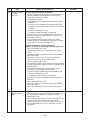
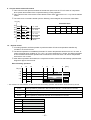
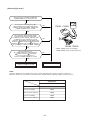
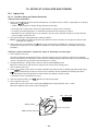
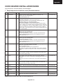
5. Coil heating control
1) This control function heats the compressor by turning on the stopped compressor instead of a case
heater. It purposes to prevent slackness of the refrigerant inside of the compressor.
2) As usual, turn on power of the compressor for the specified time before a test run after installation,
otherwise a trouble of the compressor may be caused. As same as a test run, it is recommended to turn
on power of the compressor beforehand when starting operation after power of the compressor has been
interrupted for a long time.
3) A judgment for electricity is performed by TD and TO sensors. If TO sensor is defective, a backup control
is automatically performed by TE sensor. For a case of defective TO sensor, judge it with the outdoor LED
display.
4) Coil heating is controlled by TD and TE sensor.
5) For every model, the power is turned off when TD is 30°C or more.
(In trouble of sensor)
TO [˚C]
18
Power-ON condition 15
TD < 30˚C
10
8
TO [˚C]
20
18
12
10
No power-ON
Continuous ON (L)
No power-ON
Continuous ON (L)
Continuous ON (M)
Continuous ON (M)
* TD sensor is read in once per 15 minutes
.
SM1100
SM1400
L
20W and equivalent
25W and equivalent
M
40W and equivalent
50W and equivalent
NOTIFICATION
It is not an abnormal phenomenon that electro-noise may be heard while heating the coil.
6. Short intermittent operation preventive control
Q The compressor may not stop for preventing the compressor for 3 to 10 minutes after start of the
operation even if Thermo-OFF signal has been received from the indoor. This phenomenon is not
abnormal. (Continuous operation time of the compressor differs according to the operating status.)
R If the equipment is stopped from the remote controller, the operation does not continue.
7. High-pressure suppression TE control
Q This control suppresses that pressure becomes abnormally higher during cooling operation.
R Stop the compressor under condition of TE ≥ 67°C, and count 1 on the error count.
S After 2 minutes 30 seconds passed, if TE < 67°C, the compressor restarts and the error count is
cleared when the operation continues for 10 minutes.
T When TE ≥ 67°C is detected again within 10 minutes, 1 is added to the error count and restart is
repeated.
U If the error counts 10 are recognized, it is determined as an error and restart is not performed. Error
code ‘P04’ is displayed.
V After restarting the compressor, continue controlling by using 70% to 90% of the control value of the
current release control for minimum 30 minutes.
8. Over-current preventive control
Q This control function stops the compressor when over-current preventive circuit has detected an
abnormal current.
R The compressor restarts with error count 1 after 2 minutes 30 seconds.
S If the error counts 4 are recognized, it is determined as an error and restart is not performed. Error
code ‘H01’, ‘H02’ or ‘P26’ is displayed.
– 26 –
9. Current release value shift control
Q This control function prevents troubles of the electron parts such as G-Tr of inverter of compressor
drive system and troubles of the compressor during cooling operation.
R This control function corrects the current release control value ( 1) in item 3 of 7-1. by Current release
control.
S The value to be corrected is based upon the following control diagram and correction value table.
TO [˚C]
Corrected value
T+8
T+7
T+5
T+4
T+2
T+1
T
T-1
I1 x a%
I1 x b%
T
a
b
c
d
SM1100
39°C
50%
70%
80%
90%
SM1400
39°C
70%
80%
90%
95%
I1 x c%
I1 x d%
As I1
10. Defrost control
Q In heating operation, defrost operation is performed when TE sensor temperature satisfies any
condition in A zone to D zone.
R The defrost operation is immediately finished if TE sensor temperature has become 12°C or more, or
it also is finished when condition of 7°C ≤ TE < 12°C has continued for 1 minute. The defrost operation
is also finished when defrost operation has continued for 10 minutes even if TE sensor temperature
has become 7°C or lower.
S After defrost operation has finished, the compressor and the outdoor fan start heating operation after
stopped for approx. 50 seconds.
Start of heating operation
0
TE [˚C]
10
15
c
b
a
d
[min]
–5
A zone
–10
–13
B zone
–18
D zone
C zone
*
* The minimum TE value between 10 and 15 minutes after heating operation has started is stored in memory as TE0.
A zone
Defrost operation is performed in this zone when TE0-TE ≥ 3 continued for T seconds.
B zone
Defrost operation is performed in this zone when TE0-TE ≥ 3 continued for T seconds.
C zone
Defrost operation is performed when this zone continued for T seconds.
D zone
Defrost operation is performed when this zone continued for T seconds.
SM1100, SM1400
a
34
b
40
c
55
d
90
T
20
– 27 –
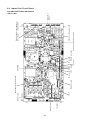
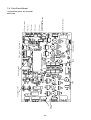
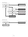
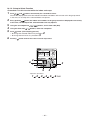
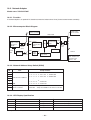
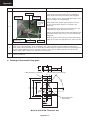
4-way valve
output
Pump down switch
GND
12V power supply
MCU
Case thermo
Status display LED
PMV output
– 28 –
Outdoor fan output
Communication
between CDB and IPDU
TS sensor
TE sensor
TO sensor
TD sensor
5V power supply
7-2. Print Circuit Board
<Viewed from parts of P.C board>
MCC-1398
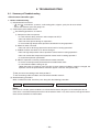
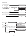
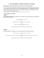
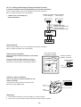
8. TROUBLESHOOTING
8-1. Summary of Troubleshooting
<Wired remote controller type>
1. Before troubleshooting
1) Required tools/instruments
• + and – screwdrivers, spanners, radio cutting pliers, nippers, push pins for reset switch
• Tester, thermometer, pressure gauge, etc.
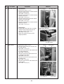
2) Confirmation points before check
Q The following operations are normal.
a) Compressor does not operate.
• Is not 3-minutes delay (3 minutes after compressor OFF)?
• Does not thermostat turn off?
• Does not timer operate during fan operation?
• Is not outside high-temperature operation controlled in heating operation?
b) Indoor fan does not rotate.
• Does not cool air discharge preventive control work in heating operation?
c) Outdoor fan does not rotate or air volume changes.
• Does not high-temperature release operation control work in heating operation?
• Does not outside low-temperature operation control work in cooling operation?
• Is not defrost operation performed?
d) ON/OFF operation cannot be performed from remote controller.
• Is not the control operation performed from outside/remote side?
• Is not automatic address being set up?
(When the power is turned on at the first time or when indoor unit address setting is changed, the
operation cannot be performed for maximum approx. 5 minutes after power-ON.)
R Did you return the cabling to the initial positions?
S Are connecting cables of indoor unit and remote controller correct?
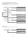
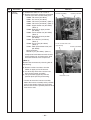
(2) Troubleshooting procedure
When a trouble occurred, check the parts along with the following procedure.
Trouble → Confirmation of check code display → Check defective position and parts.
NOTE :
For cause of a trouble, power conditions or malfunction/erroneous diagnosis of microcomputer due to
outer noise is considered except the items to be checked. If there is any noise source, change the cables
of the remote controller to shield cables.
– 29 –
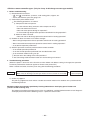
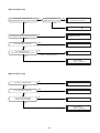
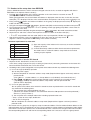
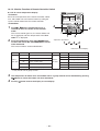
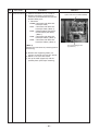
<Wireless remote controller type> (Only for 4-way air discharge cassette type models)
1. Before troubleshooting
1) Required tools/instruments
• + and – screwdrivers, spanners, radio cutting pliers, nippers, etc.
• Tester, thermometer, pressure gauge, etc.
2) Confirmation points before check
Q The following operations are normal.
a) Compressor does not operate.
• Is not 3-minutes delay (3 minutes after compressor OFF)?
• Does not thermostat turn off?
• Does not timer operate during fan operation?
• Is not outside high-temperature operation controlled in heating operation?
b) Indoor fan does not rotate.
• Does not cool air discharge preventive control work in heating operation?
3) Outdoor fan does not rotate or air volume changes.
• Does not high-temperature release operation control work in heating operation?
• Does not outside low-temperature operation control work in cooling operation?
• Is not defrost operation performed?
4) ON/OFF operation cannot be performed from remote controller.
• Is not forced operation performed?
• Is not the control operation performed from outside/remote side?
• Is not automatic address being set up?
Q Did you return the cabling to the initial positions?
R Are connecting cables between indoor unit and receiving unit correct?
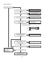
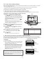
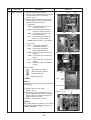
2. Troubleshooting procedure
(When the power is turned on at the first time or when indoor unit address setting is changed, the operation
cannot be performed for maximum approx. 5 minutes after power-ON.)
When a trouble occurred, check the parts along with the following procedure.
Trouble →
Confirmation of lamp display
(When 4-way air discharge cassette type wireless remote controller is connected)
→
Check defective
position and parts.
1) Outline of judgment
The primary judgment to check where a trouble occurred in indoor unit or outdoor unit is performed with
the following method.
Method to judge the erroneous position by flashing indication on the display part of indoor unit
(sensors of the receiving unit)
The indoor unit monitors operating status of the air conditioner, and the blocked contents of self-diagnosis
are displayed restricted to the following cases if a protective circuit works.
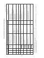
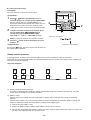
– 30 –
– 31 –
¥
¥
¥
¥
¥
l
¡
¥
¥
¥
l
l
¥
¥
¥
¥
¥
l
l
l
¥
¥
¥
¥
¥
¥
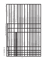
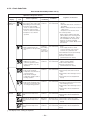
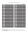
Own unit stops while warning is output to other indoor units.
Coming-off, disconnection or short of indoor heat exchanger
sensor (TCJ)
Coming-off, disconnection or short of indoor heat exchanger
sensor (TC)
Coming-off, disconnection or short of indoor heat exchanger
sensor (TA)
Indoor EEPROM error
• EEPROM access error
Communication error between indoor MCU
• Communication error between fan driving MCU and main
MCU
Regular communication error between master and sub indoor
units or between main and sub indoor units
P31
F01
F02
F10
F29
E10
E18
l
l
l
l
l
l
¥
l
l
¥
¥
Indoor DC fan error
Fan motor thermal protection
P01
P12
Abnormal outside interlock input
L30
Float switch operation
• Disconnection, coming-off, defective float switch contactor
of float circuit
Unset indoor capacity
P10
Unsetting of indoor group address
L09
There is group line in individual indoor units.
L08
L07
Duplicated indoor master units
Error in 4-way valve system
• Indoor heat exchanger temperature lowered after start of
heating operation.
¥
¥
¥
¥
L03
Duplicated indoor unit addresses
The serial signal is not output from outdoor unit to indoor unit.
• Miscabling of inter-unit cables
• Defective serial sensing circuit on outdoor P.C. board
• Defective serial receiving circuit on indoor P.C. board
E04
E08
No communication from remote controller (including wireless)
and communication adapters
Cause of operation
Diagnostic function
E03
Check code
Wired remote
controller
Stop
(Automatic reset)
Stop
(Automatic reset)
Stop
(Automatic reset)
Stop
(Automatic reset)
Stop
(Automatic reset)
Stop
(Automatic reset)
Stop (Sub unit)
(Automatic reset)
Stop
(Automatic reset)
Stop
Stop
Stop
Stop
Stop
Stop
S top
(Automatic reset)
Stop
(Automatic reset)
Status of air
conditioner
Judgment and measures
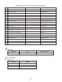
¥ : Flash, ¡ : Go on, l : Go off
Displayed when 1. Check cables of remote controller.
error is detected 2. Check indoor power cable.
3. Check indoor P.C. board.
Displayed when 1. Check cables of remote controller.
error is detected 2. Check power cables of indoor unit.
3. Check indoor P.C. board.
Displayed when 1. Check indoor EEPROM. (including socket insertion)
error is detected 2. Check indoor P.C. board.
Displayed when 1. Check indoor heat exchanger temperature sensor (TA).
error is detected 2. Check indoor P.C. board.
Displayed when 1. Check indoor heat exchanger temperature sensor (TC).
error is detected 2. Check indoor P.C. board.
Displayed when 1. Check indoor heat exchanger temperature sensor (TCJ).
error is detected 2. Check indoor P.C. board.
Displayed when 1. Judge sub unit while master unit is in [E03], [L03], [L07], [L08].
error is detected 2. Check indoor P.C. board.
Displayed when 1. Check 4-way valve.
error is detected 2. Check indoor heat exchanger (TC/TCJ) sensor.
3. Check indoor P.C. board.
Displayed when 1. Defective detection of position
error is detected 2. Over-current protective circuit of indoor fan driving unit operates.
3. Lock of indoor fan
4. Check indoor P.C. board.
Displayed when 1. Defect of drain pump
error is detected 2. Clogging of drain pump
3. Check float switch.
4. Check indoor P.C. board.
Displayed when 1. Check thermal relay of fan motor.
error is detected 2. Check indoor P.C. board.
Displayed when 1. Check outside devices.
error is detected 2. Check indoor P.C. board.
Displayed when 1. Set the indoor capacity. (DN=I1)
error is detected
Displayed when 1. Check whether there is modification of remote controller connection (Group/
error is detected
Individual) or not after power has been turned on (finish of group configuration/
address check).
* If group configuration and address are not normal when the power has been turned
on, the mode automatically shifts to address setup mode. (Resetting of address)
Displayed when 1. Outdoor unit does not completely operate.
error is detected
• Inter-unit cable check, correction of miscabling, case thermo operation
• Outdoor P.C. board check, P.C. board cables check
2. In normal operation
P.C. board (Indoor receiving/Outdoor sending) check
Displayed when 1. Check cables of remote controller and communication adapters.
error is detected
• Handy remote controller LCD display OFF (Disconnection)
• Central remote controller [97] check code
Condition
Error mode detected by indoor unit
P19
¥
¥
¥
l
l
l
l
l
¥
¥
¥
l
l
l
l
Ready
¥
Operation Timer
Wireless sensor
lamp display
8-2. Check Code List
– 32 –
¥
¥
¥
¥
¥
¥
¥
¡
¡
l
l
l
l
l
¥
¥
¥
l
¥
¥
¥
¥
¥
¥
¥
¥
¥
¥
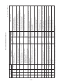
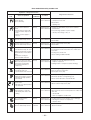
Coming-off, disconnection or short of outdoor temperature
sensor (TD)
Coming-off, disconnection or short of outdoor temperature
sensor (TE/TS)
Coming-off, disconnection or short of outdoor temperature
sensor (TO)
F06
F08
Outdoor DC fan error
P22
F04
High-pressure protection error by TE sensor
(Temperature over specified value was detected.)
P04
IPDU position detection circuit error
Discharge temperature error
• Discharge temperature over specified value was detected.
P03
P29
Phase detection protective circuit operates.
(Normal models)
L31
Inverter over-current protective circuit operates. (For a short time)
Short voltage of main circuit operates.
Outdoor unit and other errors
• Communication error between CDB and IPDU
(Coming-off of connector)
• Heat sink temperature error
(Detection of temperature over specified value)
L29
P26
Current detection circuit error
Stop
• Current value at AC side is high even during compressor-OFF.
• Phase of power supply is missed.
H03
Judgment and measures
Displayed when 1. Check cables of CDB and IPDU.
error is detected 2. Abnormal overload operation of refrigerating cycle
Displayed when 1. Compressor immediately stops even if restarted. : Check IPDU.
error is detected 2. Phase-missing operation of power supply
Check 3-phase power voltage and cables.
Displayed when 1. Trouble of compressor (Compressor lock, etc.) : Replace compressor.
error is detected 2. Defective cabling of compressor (Phase missing)
3. Phase-missing operation of power supply (3-phase model)
Displayed when 1. Check power voltage. AC200V±20V
error is detected 2. Overload operation of refrigerating cycle
3. Check current detection circuit at AC side.
Condition
¥ : Flash, ¡ : Go on, l : Go off
Displayed when 1. Check outdoor temperature sensor (TE/TS).
error is detected 2. Check outdoor CDB P.C. board.
Displayed when 1. Check outdoor temperature sensor (TD).
error is detected 2. Check outdoor CDB P.C. board.
Displayed when 1. Position detection circuit operates even if operating compressor by removing
error is detected
3P connector. : Replace IPDU.
Displayed when 1. Inverter immediately stops even if restarted. : Compressor motor rare short
error is detected 2. Check IPDU. : Cabling error
Displayed when 1. Defective detection of position
error is detected 2. Over-current protective circuit of outdoor fan driving unit operates.
3. Lock of outdoor fan
4. Check outdoor CDB P.C. board.
Displayed when 1. Overload operation of refrigerating cycle
error is detected 2. Check outdoor temperature sensor (TE).
3. Check outdoor CDB P.C. board.
Displayed when 1. Check refrigerating cycle. (Gas leak)
error is detected 2. Trouble of PMV
3. Check Td sensor.
Operation continues. Displayed when 1. Check outdoor temperature sensor (TO).
error is detected 2. Check outdoor CDB P.C. board.
Stop
Stop
Stop
Stop
Stop
Stop
Stop
Operation continues. Displayed when 1. Check power phase order (Reversed phase)/phase missing.
(Compressor stops.) error is detected 2. Check outdoor P.C. board.
Stop
Stop
Compressor does not rotate.
• Over-current protective circuit operates after specified time
passed when compressor had been activated.
H02
Stop
Status of air
conditioner
Breakdown of compressor
• Displayed when error is detected
Cause of operation
Diagnostic function
H01
Check code
Wired remote
controller
For an error mode detected in outdoor unit, the fan operates because sub unit of a group operation does not communicate with the outdoor unit.
¡
¡
¡
¥
l
l
¥
l
l
¥
Ready
l
Operation Timer
Wireless sensor
lamp display
Error mode detected by outdoor unit
– 33 –
—
—
—
—
—
—
—
Multiple master remote controllers are recognized. Stop
(Detected at remote controller side)
(Sub unit continues operation.)
E09
Displayed when Check the check code of corresponding unit by handy remote controller.
error is detected
Continuation/stop
(Based on a case)
—
Indoor Gr sub unit error
Central remote (Detected by central controller side)
controller
b7
Displayed when 1. Check multiple network adapters.
error is detected 2. Check inter-unit cable/miscabling of remote controller.
: Only one network adapter on remote controller communication line
Displayed when 1. Check address setup of central control system network.
error is detected
(Network adapter SW01)
2. Check network adapter P.C. board.
Displayed when 1. Check there are multiple master units for 2 remote controllers
error is detected
(including wireless).
: Master unit is one and others are sub units.
Displayed when Signal sending of remote controller is defective.
error is detected 1. Check sending circuit inside of remote controller.
: Replace remote controller.
Operation continues.
Displayed when 1. Check communication line/miscabling. Check power of indoor unit.
(According to handy remote controller) error is detected 2. Check communication. (XY terminals)
3. Check network adapter P.C. board.
4. Check central controller (such as central control remote controller, etc.).
Operation continues.
Stop
(Automatic restart)
Stop
(Automatic restart)
* When there is center, operation
continues.
Remote controller power error, Defective indoor EEPROM
1. Check remote controller inter-unit cables.
2. Check remote controller.
3. Check indoor power cables.
4. Check indoor P.C. board.
5. Check indoor EEPROM. (including socket insertion)
: Phenomenon of automatic address repetition occurred.
Judgment and measures
Displayed when Signal receiving of remote controller is defective.
error is detected 1. Check remote controller inter-unit cables.
2. Check remote controller.
3. Check indoor power cables.
4. Check indoor P.C. board.
—
Condition
Interruption of central control system (AI-NET)
communication circuit
Central remote (Detected by central controller side)
controller
97
—
*3
Multiple network adapters on remote controller
communication line
Central remote (Detected by central controller side)
controller
99
—
*3
L20
Duplicated indoor central addresses on
Central remote communication of central control system (AI-NET)
(Detected by central controller side)
controller
98
Signal sending error to indoor unit
(Detected at remote controller side)
E02
Stop
(Automatic restart)
* When there is center, operation
continues.
No communication with indoor master unit
• Disconnection of inter-unit cable between
remote controller and master indoor unit
(Detected at remote controller side)
E01*2
Stop
Status of air conditioner
No communication with master indoor unit
• Remote controller cable is not correctly
connected.
• Power of indoor unit is not turned on.
• Automatic address cannot be completed.
Cause of operation
Diagnostic function
No check code
is displayed.
(Remote
controller does
not operate.)
Check code
Wired remote
controller
¥ : Flash, ¡ : Go on, l : Go off
*2 Check code is not displayed by wired remote controller. (Usual operation of air conditioner is disabled.)
For wireless type models, E01 is notified by the display lamp.
*3 These errors are related to communication of remote controllers (A, B) and central system (AI-NET, X, Y), and [E01], [E02], [E03], [E09], or [E18] is displayed or no check code is displayed on the
remote controller according to the error contents.
—
—
l
l
¥
¥
l
l
¥
¡
l
l
¥
¥
—
—
Ready
—
Operation Timer
Wireless sensor
lamp display
Error mode detected by remote controller or network adapter
8-3. Error Mode Detected by LED on Outdoor P.C. Board
<SW800: LED display in bit 1, bit 2, bit 3 OFF>
• When multiple errors are detected, the latest error is displayed.
• When LED display is ¡ (Go on), there is the main cause of trouble on the objective part of control at CDB side
and the unit stops.
• When LED display is ¥ (Flash), there is the main cause of trouble on the objective part of control at IPDU
side and the unit stops.
• When case thermostat operates, the communication is interrupted on the serial circuit. If continuing the case
thermostat operation, a serial communication error occurs because serial sending to the indoor unit is interrupted.
Check code
No.
CDB side
IPDU side
¡ : Go on
Item
LED display
Type A
Type B
D800
(Red)
D801
(Yellow)
D802
(Yellow)
D803
(Yellow)
1
TE sensor error
F06
18
¡
l
l
l
2
TD sensor error
F04
19
¡
¡
l
l
3
TS sensor error
F06
18
l
l
¡
l
4
TO sensor error
F08
1B
l
¡
l
l
5
Discharge temp. error
P03
1E
l
¡
¡
l
6
DC outdoor fan error
P22
1A
¡
¡
¡
l
7
Communication error
between IPDU
(Abnormal stop)
L29
1C
¡
l
l
l
8
High-pressure release
operation
P04
l
¡
l
¡
21
—
9
EEPROM error
—
—
¡
¡
l
¡
10
Communication error
between IPDU
(No abnormal stop)
—
—
l
l
¡
¡
11
G-Tr short-circuit
protection
P26
14
¥
l
l
l
12
Detection circuit error
P29
16
l
¥
l
l
13
Current sensor error
H03
17
¥
¥
l
l
14
Phase missing detection
H03
17
l
l
l
¥
15
Comp. lock error
H02
1D
l
l
¥
l
16
Comp. breakdown
H01
1F
¥
l
¥
l
l : Go off
¥ : Flash (5Hz)
<<Check code>>
The check codes are classified into Type A and Type B according to the used remote controller. Be sure to
check the remote controller which you use.
Type A :
Neutral 2-cores type wired remote controller such as RBC-AMT21E, RBC-AS21E, and wireless remote controller kit such as TCB-AX21U (W)-E
Type B :
Central control remote controller such as RBC-CR64-PE
– 34 –
8-4. Troubleshooting Procedure for Each Check Code
8-4-1. New Check Code/Present Check Code (Central Control Side)
[E01 error]/*[99 error]
* : When central controller [99] is displayed, there are other causes of error.
NO
Correct inter-unit cable of remote controller.
Is inter-unit cable of A and B normal?
YES
Is there no disconnection
or contact error of connector on harness
from terminal block of indoor unit?
YES
Correct connection of connector.
Check circuit cables.
NO
NO
Is group control operation?
YES
NO
Check power connection of indoor unit.
(Turn on power again.)
NO
Check indoor P.C. board (MCC-1402).
Defect
Replace
YES
Correct as a master unit/a sub unit
(Remote controller address connector)
Is power of all indoor units turned on?
YES
Is power supplied to remote controller?
AB terminal: Approx. DC18V
YES
Are two remote controllers
set without master unit?
NO
Check remote controller P.C. board.
Defect
Replace
[E09 error]/*[99 error]
* : When central controller [99] is displayed, there are other causes of error.
Are two remote controllers
set without master unit?
YES
Correct as a master unit/a sub unit
(Remote controller address connector)
NO
Check remote controller P.C. board.
Defect
Replace
–35 –
[E04 error]/[04 error]
NO
Does outdoor unit operate?
YES
NO
Is setup of group address correct?
Check item code [14].
YES
NO
Correct inter-unit cable.
Are 1, 2, 3 inter-unit cables normal?
YES
Are connections from connectors
of inter-terminal blocks (1, 2, 3)
of indoor/outdoor units normal?
NO
Correct connection of connector.
YES
Does voltage between
2 and 3 of inter-terminal blocks (1, 2, 3)
of indoor unit vary?*
YES
Check indoor P.C. board
(MCC-1402).
Replace
Defect
NO
shown in the following figure,
* As
perform measurement within
20 seconds after power ON.
Black
3
S5277G
White
2
1
Inter-terminal block
Is DC280V applied between
terminals of electrolytic capacitor
of IPDU main circuit?
NO
Replace IPDU.
YES
Is DC7V power supplied to CDB?
Are cablings between Pin 2 and Pin 5
of CN800 and between IPDU
and CDB normal?
NO
Replace IPDU.
Correct connection of connector.
YES
NO
Is case thermo (CN500) connected?
YES
Check indoor P.C. board
(MCC-1402 or MCC-1403).
Defect
Replace
Check CDB.
Defect
Replace
NO
Does case thermo operate?
YES
Check/Correct charged
refrigerant amount.
– 36 –
Correct connection of connector.
[E10 error]/[CF error]
<Only for 4-way air discharge cassette type
Check indoor control P.C. board (MCC-1402).
Defect
Replace
[E18 error]/[97 error] *[99 error]
* : When central controller [99] is displayed, there are other causes of trouble.
NO
Correct inter-unit cable of remote controller.
Is inter-unit cable of A and B normal?
YES
Is there no disconnection
or contact error of connector on harness
from terminal block of indoor unit?
YES
Correct connection of connector.
Check circuit cables.
NO
NO
YES
Is group control operation?
Is power of all indoor units turned on?
NO
Check indoor P.C. board (MCC-1402).
Replace
Defect
Check power connection of indoor unit.
(Turn on power again.)
[E08, L03, L07, L08 error]/ *[96 error] [99 error]
* : When central controller [99] is displayed, there are other causes of trouble.
E08
L03
L07
L08
: Duplicated indoor unit numbers
: Two or more master units in a group control
: One or more group addresses of [Individual] in a group control
: Unset indoor group address (99)
If the above is detected when power has been turned on, the mode automatically enters in automatic address setup mode. (Check code is not displayed.)
However, if the above is detected during automatic address setup mode, the check code may be displayed.
[L09 error]/[46 error]
YES
Set capacity data of indoor unit.
(Setup item code (DN) = 11)
Is capacity of indoor unit unset?
NO
Check indoor P.C. board (MCC-1402).
Replace
Defect
– 37 –
[L20 error]/[98 error]
Are cable connections to
communication line X, Y normal?
NO
Correct cable connection
YES
Check indoor P.C. board
(MCC-1402 or MCC-1403).
Defect
Replace
NO
Is central controller [98] displayed?
YES
Is indoor remote controller
[L20] displayed?
YES
Are not multiple
same central control network
addresses connected?
YES
Correct central control network address.
NO
Check central controller
(including network adapter).
Defect
Replace.
[L30 error]/[B6 error]
Are outside devices of
connector CN80 connected?
NO
Check indoor P.C. board
(MCC-1402 or MCC-1403).
Defect
Replace
NO
Check outside devices.
Replace
Defect
YES
Do outside devices normally operate?
YES
Check operation cause.
[b7 error] (Central controller)
NO
Is group operation performed?
YES
Is check code displayed on sub unit
of main or sub remote controller?
Check indoor P.C. board
(MCC-1402 or MCC-1403).
Defect
Replace
NO
YES
Check corresponding
indoor/outdoor units.
– 38 –
[P10 error]/[0b error]
NO
Is connection of float switch connector
(Indoor control P.C. board CH34) normal?
Correct connection of connector.
YES
NO
Does float switch operate?
YES
NO
Is circuit cabling normal?
Check and correct cabling/wiring.
YES
Check indoor P.C. board
(MCC-1402 or MCC-1403).
Defect
Replace
NO
Does drain pump operate?
YES
NO
Is power of drain pump turned on?
Check indoor P.C. board
(MCC-1402 or MCC-1403).
Defect
Replace
YES
Check drain pipe, etc.
Replace drain pump.
Check cabling.
[F10 error] [0C error]
Is connection of TA sensor connector
(indoor P.C. board CN104) normal?
NO
Correct connection of connector.
YES
Are characteristics of TA sensor
resistance value normal?
NO
Replace TA sensor.
YES
* Refer to Characteristics-1.
Check indoor P.C. board
(MCC-1402 or MCC-1403).
Defect
Replace
– 39 –
[P12 error]/[11 error]
<Only for 4-way air discharge cassette type models (RAV-SM1100UT-E/RAV-SM1400UT-E)>
Turn off the power.
Are not there connections errors or
disconnection on connectors CN333 and CN334
of indoor unit P.C. board (MCC-1402)?
YES
Correct connection of connector.
NO
Remove connectors CN333 and
CN334 of indoor unit P.C. board
(MCC-1402).
Does the fan rotate without trouble
when handling the fan with hands?
NO
Replace indoor fan motor.
YES
Are resistance values between phases
at fan motor connector CN333 motor side of
indoor P.C. board (MCC-1402) correct? *1
YES
Is resistance value of fan motor connector
CN333 at motor side of indoor P.C. board
(MCC-1402) correct? *2
YES
Is signal output of indoor fan motor
position detection correct? *3
YES
NO
Replace indoor fan motor.
*1
• Are not coil windings between 1 (Red lead) and 3 (White lead),
between 3 (White lead) and 5 (Black lead), between
5 (Black lead) and 1 (Red lead) opened or shorted?
For resistance, see the following values.
Approx. 70 to 100
SM1100
SM1400
Approx. 35 to 60
• Is not earthed between cabinet and 1, 3, 5
10M or more
NO
Replace indoor fan motor.
*2
Check resistance of fan motor position detection circuit.
Is not coil winding between 1 (Yellow lead) and 4 (Pink lead)
opened or shorted?
Resistance: Approx. 5 to 20k
NO
Replace indoor fan motor.
*3
Check fan motor position detection signal.
• Using a tester, measure the voltage between CN334 1 and 5 of
indoor P.C. board (MCC-1402) under condition that CN333 and
CN334 are mounted and the power is turned on.
® Rotate the fan slowly with hands,
and check the pin voltage
swings between 0 to 5V voltage.
• Between 4 and 5 : 5V
CN333
Check indoor P.C. board
(MCC-1402).
Defect
Replace
CN334
–40 –
[P22 error]/[1A error]
Are connections of CN301, CN303 and
CN300, CN302 of P.C. board correct?
YES
Does the fan rotate without trouble
when handling the fan with hands under
condition of removing CN301, CN303 and
CN300, CN302 from P.C. board?
NO
CN301, CN303
YES
The status that the resistance values
between leads below are 50 to 80W
for 43W motor (ICF-140-43) and 25 to 55W
for 63W motor (ICF-140-63) is normal.
Between 1 (Red lead) and 2 (White lead)
Between 2 (White lead) and 3 (Black lead)
Between 3 (Black lead) and 1 (Red lead) of
motor winding of connector (CN301, CN303)
NO
CN300, CN302
YES
The status that there is
5k to 20kW resistance values between
1 (Yellow lead) and 4 (Pink lead)
of motor position detection of
connector (CN300, CN302) is normal.
* CN301, CN303 : Motor coil winding
CN300, CN302 : Motor position detection
NO
YES
Normal fan motor
(Control or CDB P.C. board)
Defective fan motor
(Control P.C. board or CDB P.C. board)
NOTE :
However, GND circuit error inside of the motor is rarely detected even if the above check is carried out.
When the circuit does not become normal even if P.C. board has been replaced, replace outdoor fan motor.
Single phase
RAV-SM1100AT-E, RAV-SM1400AT-E
Objective P.C. board
CDB P.C. board
Fan motor winding
CN301
Motor position detection
CN300
Fan motor winding
CN303
Motor position detection
CN302
– 41 –
[P19 error]/[08 error]
Is operation of
4-way valve normal?
NO
Is voltage applied
to 4-way valve coil terminal
in heating operation?
YES
NO
NO
YES
Is flow of refrigerant
by electron expansion
valve normal?
Check 4-way valve
Defect
Replace
YES
Check and replace
electron expansion
valve.
NO
Is circuit cable normal?
YES
NO
Check and correct circuit.
Are characteristics
of TC sensor resistance
value normal?
* Refer to Characteristics-2. YES
NO
Check CDB P.C. board.
Replace TC sensor.
YES
Check CDB P.C. board.
Replace
Defect
Check indoor P.C. board.
Replace
Defect
• In cooling operation, if high pressure is abnormally raised, [P19 error]/[08 error] may be displayed. In this
case, remove cause of pressure up and then check again referring to the item [P04 error]/[21 error].
[F02 error]/[0d error]
Is connection of TC sensor connector
(Indoor P.C. board CN101) normal?
NO
Correct connection of connector.
YES
Are characteristics of
TC sensor resistance value normal?
YES
NO
Replace TC sensor.
* Refer to Characteristics-2.
Check indoor P.C. board
(MCC-1402).
Defect
Replace
– 42 –
[F01 error]/[0F error]
Is connection of TCJ sensor connector
(Indoor P.C. board CN102) normal?
NO
Correct connection of connector.
YES
Are characteristics of
TCJ sensor resistance value normal?
YES
NO
Replace TCJ sensor.
* Refer to Characteristics-2.
Check indoor P.C. board
(MCC-1403).
Defect
Replace
[P26 error]/[14 error]
NO
Improve the power supply line.
Is power voltage normal?
YES
Are connections of
cabling/connector normal?
Check and correct circuit cables.
Correct connection of connector.
Check and correct reactor connection.
NO
YES
Does RY01 relay of
IPDU operate?
YES
Are not “P26” and “14” errors output
when an operation is performed by
removing 3P connector of compressor?
NO
NO
YES
Replace IPDU.
YES
Is not AC fuse fused?
* Replace control P.C. board
of outdoor unit.
NO
Replace IPDU.
NO
* Replace control P.C. board
of outdoor unit.
Is compressor normal?
YES
Check IPDU.
Defect
Replace
Check rare short of compressor trouble.
Defect
Replace
– 43 –
[P29 error]/[16 error]
NO
Are connections of
cable/connector normal?
Check and correct circuit cabling
such as cabling to compressor.
YES
NO
Is compressor normal?
YES
YES
Is not earthed?
Compressor error
Replace
Compressor error
Replace
Compressor error
Replace
NO
Is not winding shorted?
(Is resistance between windings 0.6 to 1.2W?)
YES
NO
YES
Is not winding opened?
NO
Check IPDU P.C. board.
Defect
Replace
[H03 error]/[17 error]
Are cablings of power and
current sensor normal?
NO
Check and correct circuit cables.
YES
Check IPDU.
Defect
Replace
– 44 –
[F06 error]/[18 error]
Are connections of
TE/TS sensor connectors of
CDB CN604/CN605 normal?
NO
Correct connection of connector.
YES
Are characteristics of TE/TS sensor
resistance values normal?
NO
Replace TE and TS sensors.
YES
Check CDB.
Defect
Replace
* Refer to Characteristics-3.
[F04 error]/[19 error]
Is connection of TD sensor connector
of CDB CN600 normal?
NO
Correct connection of connector.
YES
Are characteristics of TD sensor
resistance value normal?
NO
Replace TD sensor.
YES
Check control P.C. board.
Defect
Replace
* Refer to Characteristics-4.
[F08 error]/[1b error]
Is connection of TO sensor connector
of CDB CN601 normal?
NO
Correct connection of connector.
YES
Are characteristics of TO sensor
resistance value normal?
NO
Replace TO sensor.
YES
Check CDB.
Defect
Replace
* Refer to Characteristics-5.
– 45 –
[L29 error]/[1C error]
Are connections of
CDB CN800 and CDB IPDU CN06
connectors normal?
NO
Correct connection of connector.
YES
Was the error just after
power ON determined?
YES
NO
Are cabling/connector normal?
Check cabling between IPDU
and CDB and connector.
YES
NO
IPDU P.C. board error
Replace
Defect
YES
Improve and eliminate the cause.
Is there no abnormal overload?
NO
Is IPDU P.C. board come to
closely contact with heat sink?
NO
Correct mounting.
YES
IPDU P.C. board error
Replace
Defect
[H02 error]/[1d error]
NO
Improve power line.
Is power voltage normal?
YES
Are connections of
cable/connector normal?
Check and correct circuit cabling such
as cabling to compressor
(phase missing) and connector.
NO
YES
NO
Is compressor normal?
YES
Is there no
slackened refrigerant?
NO
Compressor lock
Replace
YES
Does electron expansion
valve normally operate?
YES
Check IPDU and CDB.
Replace
Defect
– 46 –
NO
Check TE and TS sensors. Replace
Check electron expansion valve. Replace
[P03 error]/[1E error]
Is protective control such as
discharge temprelease control normal?
NO
Are connections of
cable/connector normal?
YES
NO
Correct the cabling and
connection of connector.
YES
Check parts. Defect
NO
Replace
Check and correct the charged
refrigerant amount.
Is charged refrigerant amount normal?
YES
YES
Improve and delete the cause
Is not abnormal overload?
NO
Are characteristics of
TD sensor resistance value normal?
YES
NO
Replace TD sensor.
* Refer to Characteristics-4.
Check CDB.
Defect
Replace
[H01 error]/[1F error]
Is power voltage normal?
NO
Improve power line.
YES
YES
Improve and delete the cause.
Is not abnormal overload?
NO
Is the circuit detected by
current sensor normal?
NO
Check and correct circuit cables.
YES
Check IPDU.
Defect
Replace
– 47 –
[P04 error]/[21 error]
Is high-voltage
protective operation by
TE sensor normal?
NO
YES
NO
Is connection of cabling
connector normal?
Correct connection of
cabling connector.
YES
Check TE sensor.
Defect
Replace
NO
Does cooling outdoor fan
normally operate?
YES
NO
Is connection of
connector normal?
Correct connection of
connector.
YES
NO
Is fan motor normal?
Replace fan motor.
YES
NO
Does PMV normally operate?
YES
Do not TD and TO sensors
come off the detection part?
Correct coming-off.
YES
Check TE, TC, TS sensors.
Replace electron expansion valve.
Are characteristics of
TD, TO, TC sensor resistance
values normal?
YES
Check charged refrigerant amount.
Check liquid/gas valves.
Check abnormal overload.
NO
Check CDB.
Defect
Replace
– 48 –
NO
Replace TD, TO,
and TC sensors.
* Refer to Characteristics-3 and 4.
[97 error] (Central controller)
NO
Correct communication line.
Is X, Y communication line normal?
YES
Are connections between connectors
CN02, CN03 of network adapter P.C. board
and connectors CN309, CN41 of indoor P.C. board
(MCC-1402 or MCC-1403, normal?
NO
Correct connection of connector.
YES
NO
Is A, B communication line normal?
Check connections of A, B terminal blocks.
Correct communication line of remote controller.
YES
YES
Correct power cable.
Is there no connection error of power line?
NO
YES
Turn on the source power supply.
Is not power of source power supply turned on?
NO
YES
Clear the check code.
Did a power failure occur?
NO
YES
Is the network address changed
form remote controller?
NO
YES
Eliminate noise, etc.
Is there no noise source, etc.?
NO
Can central remote controller
control normally other indoor units?
Is handling of central remote controller reflected
on the operation status of indoor unit?
NO
(Same as others)
Check central controller.
Replace
Defect
YES
Does network adapter P.C. board
LED (D01) go on?
NO
YES
Can handy remote controller control
normally other indoor units?
NO
YES
Check network adapter P.C. board and power transformer.
Defect
Replace
– 49 –
Check indoor P.C. board
(MCC-1402 or MCC-1403).
Defect
Replace
[E03 error] (Master indoor unit)
[E03 error] is detected when the indoor unit cannot receive a signal sent from the main remote controller (and
central controller).
In this case, check the communication cables of the remote controllers A and B, the central control system X
and Y. As communication is disabled, [E03] is not displayed on the main remote controller and the central
controller. [E01] is displayed on the main remote controller and [97 error] on the central controller, respectively.
If [E03] occurs during an operation, the air conditioner stops.
[F29 error] / [12 error]
[F29 error] or [12 error] indicates detection of trouble which occurred on IC10 non-volatile memory (EEPROM)
on the indoor unit P.C. board during operation of the air conditioner. Replace the service P.C. board.
* If EEPROM has not been inserted when the power was turned on or if EEPROM data never be read/written,
the automatic address mode is repeated. In this time, the central controller displays [97 error].
(Power ON)
(Approx. 3 minutes)
[SET] is displayed on
main remote controller.
(Approx. 1 minute)
[SET] goes off.
(Repetition)
LED (D02) on
indoor unit P.C. board flashes
with 1Hz for approx. 10 seconds.
Reboot
(Reset)
[P31 error] (Sub indoor unit)
When the master unit of a group operation has detected [E03], [L03], [L07], or [L08] error, the sub unit of the
group operation detects [P31 error] and then it stops. There is no display of the check code or alarm history of
the main remote controller.
(In this model, the mode enters in automatic address set mode when the master unit has detected [E03], [L03],
[L07], or [L08] error.)
– 50 –
8-4-2. Relational Graph of Temperature Sensor Resistance Value and Temperature
20
40
TA sensor
TC, TCJ sensor
30
Caracteristics-2
Caracteristics-1
Resistance
(k )
Resistance
(k )
10
20
10
0
10
20
30
40
0
–10
50
0
10
Temperature [˚C]
20
30
40
50
60
70
Temperature [˚C]
20
200
TE, TO, TS sensor
Caracteristics-3
Resistance
(k )
(10˚C or higher)
Resistance
(k )
(10˚C or lower)
10
100
0
0
-10
0
10
20
30
40
50
60
70
Temperature [˚C]
TD sensor
200
20
Caracteristics-4
Resistance
(k )
(50˚C or higher)
Resistance
(k )
(50˚C or lower)
10
100
0
0
50
100
Temperature [˚C]
– 51 –
8-5. Troubleshooting
8-5-1. Troubleshooting with CHECK Display of Central Remote Controller
1. Operation for CHECK display
When pushing the CHECK switch, the indoor unit No. (Network address No.) including the check data is
displayed in the UNIT No. display section, and the check code is displayed in the set up temp. display section.
CHECK switch
ON
MONITOR ZONE
SET
ALL
ON
OFF
UNIT
CENTER
LOCKED
MODE
FAN ONLY
COOL
DRY
HEAT
AUTO
1 2 3 4 5 6 7 8 9 10 11 12 13 14 15 16
17 18 19 20 21 22 23 24 25 26 27 28 29 30 31 32
33 34 35 36 37 38 39 40 41 42 43 44 45 46 47 48
49 50 51 52 53 54 55 56 57 58 59 60 61 62 63 64
MONITOR/SET ALL/ZONE
ZONE
UNIT
ZONE SET/ENTER SELECT
ON CENTER/LOCKED MODE
OFF
TIMER ON
Push for 0.5 seconds to display CHECK code.
Push for 3 seconds to reset indoor microprocessor.
(While indoor microprocessor is locked by ALL STOP alarm)
Push for 10 seconds to clear check data.
AUX. TYPE
STANDBY
TIMER No.
FILTER
FAN TEMP. CHECK
AUTO 1
˚C
HIGH 2
MED.
LOW LOUVER
FIX MANUAL
TEMP. FILTER RESET CHECK
FAN
RESET switch
LOUVER
Push the switch in the hole with pin.
The remote controller resets initialized.
(All data is cleared.)
2. Reading of CHECK monitor display
<7 segment display>
Hexadecimal
notation
0
1
2
3
4
5
6
7
8
9
10
11
12
13
14
15
Decimal notation
<Display on CHECK monitor>
Unit line No. (Network address No.)
MONITOR ZONE
SET
ALL
UNIT
ON
OFF
1 2 3 4 5 6 7 8 9 10 11 12 13 14 15 16
17 18 19 20 21 22 23 24 25 26 27 28 29 30 31 32
33 34 35 36 37 38 39 40 41 42 43 44 45 46 47 48
49 50 51 52 53 54 55 56 57 58 59 60 61 62 63 64
CENTER
LOCKED
MODE
FAN ONLY
COOL
DRY
HEAT
AUTO
AUX. TYPE
STANDBY
TIMER No.
FILTER
FAN TEMP. CHECK
AUTO 1
˚C
HIGH 2
MED.
LOW LOUVER
FIX MANUAL
(Example)
There is no check data.
Check code detected at first
Check code detected at last
UNIT
TEMP. CHECK
<CHECK data>
(Example)
In No.1 unit, first the interconnection wire (bus communication line) of indoor/outdoor has failed.
Next, the room temp. sensor is defective.
For No.16 unit, the high pressure switch at the inverter unit side operates.
UNIT
UNIT
UNIT
TEMP. CHECK
1
TEMP. CHECK
2
– 52 –
TEMP. CHECK
1
8-5-2. Check Code Table
Error mode detected by indoor unit (1)
Operation of diagnostic function
Block
display
Check
code
[MODE]
[TIMER] lamp
5Hz flash
Cause of operation
Status of air
conditioner
The serial signal is not output
Operation
from outdoor unit to indoor unit. continues
• Miscabling of inter-unit cables
Judgment and measures
Condition
Displayed when 1. Outdoor unit does not completely
error is detected
operate.
• Inter-unit cable check, correction of
miscabling
• Defective serial sending
circuit on outdoor P.C. board
• Outdoor P.C. board check, P.C. board
cables check
• Defective serial receiving
circuit on outdoor P.C. board
• Compressor case thermo check
• Compressor case thermo
operation
2. In normal operation
When outdoor sending serial LED
(Green) flashes, the receiving serial
LED (Orange) also flashes. : Indoor
P.C. board (Main P.C. board) check
When the receiving serial LED
(Orange) does not flash: Outdoor P.C.
board check
BUS communication circuit error Operation
Displayed when 1. Communication line check, miscabling
continues
error is detected
check
* BUS communication was
Power supply check for central
interrupted over the specified (According
to remote
controller (Central control remote
time.
controller of
controller, etc.) and indoor unit
indoor unit)
2. Communication check (XY terminal)
3. Indoor P.C. board check
4. Central controller check
(Communication P.C. board)
Network address miss-setting
• Addresses of central
controllers (Central control
remote controller, etc.) are
duplicated.
Operation
continues
2. Indoor P.C. board check
3. Central controller check
(Communication P.C. board)
Error in 4-way valve system
Operation
continues
• Indoor heat exchanger
temperature rise after start of
cooling operation.
• Indoor heat exchanger
temperature fall after start of
heating operation.
Error in other cycles
• Indoor heat exchanger temp
(TC) does not vary after start
of cooling/heating operation.
Displayed when 1. Check central control system network
error is detected
address setting. (SW02)
Displayed when 1. Check 4-way valve.
error is detected 2. Check 2-way valve and non-return
valve.
3. Check indoor heat exchanger sensor
(TC).
4. Check indoor P.C. board (Main P.C.
board).
Operation
continues
Displayed when 1. Compressor case thermo operation
error is detected 2. Coming-off of detection part of indoor
heat exchanger sensor
3. Check indoor heat exchanger sensor
(TC).
*
4. Check indoor P.C. board (Main P.C.
board).
[MODE] lamp
5Hz flash
Coming-off, disconnection or
short of indoor temp sensor
(TA)
Operation
continues
Displayed when 1. Check indoor temp sensor (TA).
error is detected 2. Check indoor P.C. board (Main P.C.
board).
Coming-off, disconnection or
short of indoor temp sensor
(TC)
Operation
continues
Displayed when 1. Check indoor temp sensor (TC).
error is detected 2. Check indoor P.C. board (Main P.C.
board).
Coming-off, disconnection or
short of indoor temp sensor
(TCJ)
Operation
continues
Displayed when 1. Check indoor temp sensor (TCJ).
error is detected 2. Check indoor P.C. board (Main P.C.
board).
* : No display in the setting at shipment
– 53 –
Error mode detected by indoor unit (1)
Operation of diagnostic function
Block
display
Check
code
[MODE] lamp
5Hz flash
Cause of operation
Error in indoor fan system
Status of air
conditioner
All stop
Revolutions frequency error of
fan
Judgment and measures
Condition
Displayed when 1. Check indoor fan motor connector
error is detected
circuit (CN210).
2. Check indoor fan.
3. Check indoor P.C. board (Main P.C.
board).
Error in indoor unit or other
positions
Operation
continues
Displayed when 1. Check indoor P.C. board
error is detected
(EEPROM and peripheral circuits)
(Main P.C. board).
Operation
continues
Displayed when 1. Check outside devices.
error is detected 2. Check indoor P.C. board (Main P.C.
board).
All stop
Displayed when 1. Check outside devices.
error is detected 2. Check indoor P.C. board (Main P.C.
board).
1. EEPROM access error
Outside error input
Detected by input voltage level
from outside devices
Outside interlock input
Detected by input voltage level
from outside devices
Error mode detected by indoor unit (2)
Operation of diagnostic function
Check
code
Cause of operation
Serial return signal is not sent
from No. 1 indoor unit to
remote controller.
Status of air
conditioner
ON/OFF
Judgment and measures
Condition
Displayed when 1. Indoor unit does not completely operate.
error is detected
• Check inter-unit cable.
• Check indoor P.C. board. (Main/Sub P.C. boards)
• Miscabling of inter-unit cable
between remote controller
and indoor unit
• Check remote controller.
2. In normal operation
• Miss-setting of indoor unit No.
(Group address)
• Check setting of indoor unit No.
(SW01) (Sub P.C. board)
• Check remote controller.
– 54 –
Error mode detected by outdoor unit
Operation of diagnostic function
Check
code
Cause of operation
Inverter over-current protective
circuit operates.
(For a short time)
Status of air
conditioner
All stop
Judgment and measures
Condition
Displayed when 1. Inverter immediately stops even if restarted.
error is detected
• Compressor rare short
2. Check IPDU.
• Cabling error
Error on current detection
circuit
All stop
Displayed when 1. Compressor immediately stops even if restarted.
error is detected
: Check IPDU.
• Current value is high at AC
side even while compressor
stops.
2. Phase-missing operation of power supply
• Check power voltage of R, S, T.
• Phase of power supply is
missed.
Coming-off, disconnection or
short of outdoor temp sensor
All stop
Displayed when 1. Check outdoor temp sensor (TE, TS).
error is detected 2. Check CDB.
Coming-off, disconnection or
short of outdoor temp sensor
All stop
Displayed when 1. Check outdoor temp sensor (TD).
error is detected 2. Check CDB.
Compressor drive output error
All stop
Displayed when 1. Abnormal overload operation of refrigerating cycle
error is detected 2. Loosening of screws and contact error of IPDU and
heat sink
• Tin thermistor temp, Tin error
(IPDU heat sink temp. is high.)
3. Cooling error of heat sink
Communication error between
IPDU
4. Check cabling of CDB and IPDU.
• Connector coming-off
between CDB and IPDU
Compressor does not rotate.
All stop
(Over-current protective circuit
works when constant time
passed after activation of
compressor.)
Discharge temp error
2. Cabling trouble of compressor (Phase missing)
All stop
• Discharge temp over
specified value was detected.
Compressor breakdown
Displayed when 1. Check refrigerating cycle. (Gas leak)
error is detected 2. Error of electron control valve
3. Check pipe sensor (TD).
All stop
• Operation frequency lowered
and stops though operation
had started.
High-voltage protection error
by TE sensor
Displayed when 1. Compressor error (Compressor lock, etc.)
error is detected
: Replace compressor.
Displayed when 1. Check power voltage. (AC200V±20V)
error is detected 2. Overload operation of refrigerating cycle
3. Check current detection circuit at AC side.
All stop
Displayed when 1. Overload operation of refrigerating cycle
error is detected 2. Check outdoor temp sensor (TE).
All stop
Displayed when 1. Position detection error
error is detected 2. Over-current protection circuit operation of outdoor fan
drive unit
• TE temp over specified value
was detected.
DC outdoor fan motor error
• IDC operation or lock was
detected by DC outdoor fan
driving.
• Check CDB.
• Refer to Judgment of outdoor fan.
Error on IPDU position
detection circuit
All stop
Displayed when 1. Position detection circuit operates even if driving by
error is detected
removing 3P connector of compressor.
• Replace IPDU.
Coming-off, disconnection or
short of outdoor temp sensor
Operation
continues
Displayed when 1. Check outdoor temp sensor (TO).
error is detected 2. Check P.C. board.
– 55 –
9. REPLACEMENT OF SERVICE INDOOR P.C. BOARD
[Requirement when replacing the service indoor P.C. board assembly]
In the non-volatile memory (Hereinafter said EEPROM, IC10) installed on the indoor P.C. board before replacement, the type and capacity code exclusive to the corresponding model have been stored at shipment from the
factory and the important setup data such as system/indoor/group address set in (AUTO/MANUAL) mode or
setting of high ceiling selection have been stored at installation time. Replace the service indoor P.C. board
assembly according to the following procedure.
After replacement, check the indoor unit address and also the cycle by a test run.
<REPLACEMENT PROCEDURE>
CASE 1
Before replacement, power of the indoor unit can be turned on and the setup data can be readout from
the wired remote controller.
Read EEPROM data *1 (ref. P53)
ò
Replace service P.C. board & power ON *2 (ref. P53)
ò
Write the read data to EEPROM *3 (ref. P54)
ò
Power reset (All indoor units in the group when group operation)
CASE 2
Before replacement the setup data can not be readout from the wired remote controller.
Replace service P.C. board & power ON *2 (ref. P53)
ò
Write the data such as high ceiling setup to EEPROM (According to the customers’ information) *3
ò
Power reset (All indoor units in the group when group operation)
– 56 –
H1 Readout of the setup data from EEPROM
(Data in EEPROM contents, which have been changed at the local site, are read out together with data in
EEPROM set at shipment from the factory.)
buttons of the remote controller at the same time for 4 seconds or more.
1. Push SET , , and
(Corresponded with No. in Remote controller)
When group operation, the master indoor unit address is displayed at the first time. In this time, the item
code (DN) 10 is displayed. The fan of the selected indoor unit operates and the flap starts swinging if any.
button, the indoor unit address in the group are displayed successively.
Specify the
2. Every pushing
indoor unit No. to be replaced.
/
buttons, the item code (DN) can be moved up and down one by one.
3. Using the set temperature
4. First change the item code (DN) from 10 to 01. (Setting of filter sign lighting time) Make a note of the set
data displayed in this time.
/
buttons. Also make a note of the set data.
5. Next change the item code (DN) using the set temperature
6. Repeat item 5. and make a note of the important set data as shown in the later table (Ex.).
• 01 to 9F are provided in the item code (DN). On the way of operation, DN No. may come out.
button to return the status to usual stop status.
7. After finishing making a note, push
(Approx. 1 minute is required to start handling of the remote controller.)
1
2
3
6
Minimum requirements for item code
DN
Contents
10
Type
11
Indoor unit capacity
12
Line address
13
Indoor address
14
Group address
(1) Type and capacity of the indoor unit is necessary to set the revolutions
frequency of the fan.
(2) If Line/Indoor/Group addresses differ from those before replacement,
the mode enters in automatic address setup mode and a manual
resetting may be required.
H2 Replacement of service P.C. board
1. Replace the P.C. board with a service P.C. board.
In this time, setting of jumper line (cut) or setting of (short-circuit) connecting connectors on the former P.C.
board should be reflected on the service P.C. board.
2. According to the system configuration, turn on power of the indoor unit with any method in the following items.
a) In case of single (individual) operation
Turn on the power supply.
1) Wait for completion of automatic address setup mode (Required time: Approx. 5 minutes) and then
proceed to H3.
(Line address = 1, Indoor address = 1, Group address = 0 (Individual) are automatically set.)
buttons of the remote controller at the same time for 4 seconds or more
2) Push SET , , and
( operation), interrupt the automatic address setup mode, and then proceed to H3.
(Unit No. ALL is displayed.)
b) In case of group operation
Turn on power of the indoor unit of which P.C. board has been replaced with the service P.C. board with
any method in the following items.
1) Turn on power of the replaced indoor unit only.
(However, the remote controller is also connected. Otherwise H3 operation cannot be performed.)
Same as 1) and 2) in item a).
2) Turn on power of the multiple indoor units including replaced indoor unit.
• Only 1 system for twin, triple, double twin
• For all units in the group
Wait for completion of automatic address setup mode (Required time: Approx. 5 minutes) and then
proceed to H3.
* The master unit of a group may change by setup of automatic address. The line address/indoor address of the
replaced indoor unit are automatically set to the vacant addresses except addresses belonging to other indoor
units which have not been replaced. It is recommended to make a note that the refrigerant line which includes
the corresponding indoor unit and that the corresponding indoor unit is master or sub in the group control.
1
– 57 –
H3 Writing of the setup contents to EEPROM
(The contents of EEPROM installed on the service P.C. board have been set up at shipment from the factory.)
buttons of the remote controller at the same time for 4 seconds or more.
1. Push SET , , and
(Corresponded with No. in Remote controller )
In group operation control, the master indoor unit No. is displayed at the first time. (If the automatic address
setup mode is interrupted in item 2. - a) - 2) in the previous page, the unit No. ALL is displayed.) In this time,
the item code (DN) 10 is displayed. The fan of the selected indoor unit operates and the flap starts swinging
if any.
1
2
button, the indoor unit numbers in the group control are displayed successively.
2. Every pushing
Specify the indoor unit No. of which P.C. board has been replaced with a service P.C. board.
(When the unit No. ALL is displayed, this operation cannot be performed.)
3. Using the set temperature
/
buttons, the item code (DN) can be moved up and down one by one.
4. First set a type and capacity of the indoor unit.
(Setting the type and capacity writes the data at shipment from the factory in EEPROM.)
1) Set the item code (DN) to 10. (As it is)
/
buttons, set up a type.
2) Using the timer time
(For example, 4-way air discharge cassette type is 0001) Refer to the attached table.
3
4
3) Push
SET
button. (OK when the display goes on.)
5
4) Using the set temperature
/
buttons, set 11 to the item code (DN).
/
buttons, set the capacity.
5) Using the timer time
(For example, 0012 for class 80) Refer to the attached table.
6) Push
SET
button. (OK when the display goes on.)
6
button to return the status to usual stop status.
7) Push
(Approx. 1 minute is required to start handling of the remote controller.)
5. Next write the contents which have been set up at the local site such as the address setup in EEPROM.
Repeat the above procedure 1. and 2.
/
buttons, set 01 to the item code (DN).
6. Using the set temperature
(Setup of lighting time of filter sign)
7. The contents of the displayed setup data in this time should be agreed with the contents in the previous
memorandum in H1.
1) If data disagree, change the displayed setup data to that in the previous memorandum by the timer time
/
buttons, and then push SET button. (OK when the display goes on.)
2) There is nothing to do when data agrees.
/
buttons, change the item code (DN).
8. Using the set temperature
As same as the above, check the contents of the setup data and then change them to data contents in the
previous memorandum.
9. Then repeat the procedure 7. and 8.
button to return
10. After completion of setup, push
the status to the usual stop status.
(Approx. 1 minute is required to start handling of
the remote controller.)
* 01 to 9F are provided in the item code (DN).
On the way of operation, DN No. may come out.
When data has been changed by mistake and SET
button has been pushed, the data can be returned
to the data before change by pushing
button if
the item code (DN) was not yet changed.
6
SET DATA
UNIT No.
R.C.
6
4
1
UNIT
SET
5
– 58 –
No.
CL
2
3
Memorandum for setup contents (Item code table (Example))
DN
Item
At shipment
01
Filter sign lighting time
According to type
02
Dirty state of filter
0000: Standard
03
Central control address
0099: Unfixed
06
Heating suction temp shift
0002: +2°C (Floor type: 0)
0F
Cooling only
0000: Shared for cooling/heating
10
Type
According to model type
11
Indoor unit capacity
According to capacity type
12
Line address
0099: Unfixed
13
Indoor unit address
0099: Unfixed
14
Group address
0099: Unfixed
19
Flap type (Adjustment of air direction)
According to type
1E
Temp difference of automatic cooling/
heating selecting control points
0003: 3 deg (Ts ± 1.5)
28
Automatic reset of power failure
0000: None
2A
Option
0002:
2b
Thermo output selection (T10 ‡B)
0000: Thermo ON
32
Sensor selection
0000: Body sensor
5d
High ceiling selection
0000: Standard
60
Timer set (Wired remote controller)
0000: Available
8b
Correction of high heat feeling
0000: None
Memo
Type
Item code [10]
Setup data
0038
Type
Abbreviated name
4-way air discharge cassette
Indoor unit capacity
Item code [11]
Setup data
Model
0000*
Invalid
0015
110
0017
140
* Initial setup value of EEPROM installed on the service P.C. board
– 59 –
RAV-SM1100/1400UT-E
10. SETUP AT LOCAL SITE AND OTHERS
10-1. Indoor Unit
10-1-1. Test Run Setup on Remote Controller
<Wired remote controller>
1. When pushing
button on the remote controller for 4 seconds or more, “TEST” is displayed on LC display.
button.
Then push
• “TEST” is displayed on LC display during operation of Test Run.
• During Test Run, temperature cannot be adjusted but air volume can be selected.
• In heating and cooling operation, a command to fix the Test Run frequency is output.
• Detection of error is performed as usual. However, do not use this function except case of Test Run because it applies load on the unit.
2. Use either heating or cooling operation mode for [TEST].
NOTE : The outdoor unit does not operate after power has been turned on or for approx. 3 minutes after
operation has stopped.
button again and check that [TEST] on LC display has gone off.
3. After a Test Run has finished, push
(To prevent a continuous test run operation, 60-minutes timer release function is provided to this remote
controller.)
<Wireless remote controller> (Option for 4-way air discharge cassette type)
1. Turn off power of the unit.
Remove the adjuster attached with sensors from the ceiling panel. For removing, refer to the Installation
manual attached to the ceiling panel. (Be careful to handle the adjuster because cables are connected to the
sensor.) Remove the sensor cover from the adjuster. (1 screw)
2. Change ON of Bit [1: TEST] of the sensor P.C. board switch [S003] to OFF.
Mount the sensor cover and mount the adjuster with sensor to the ceiling panel.
Turn on power of the unit.
button on the wireless remote controller and select [COOL] or [HEAT] operation mode using
3. Push
button. (All the display lamps of sensors on the wireless remote controller flash during Test Run.)
• Do not perform Test Run operation in other modes than [HEAT] / [COOL] mode.
• Detection of error is performed as usual.
button to stop the operation.
4. After Test Run operation, push
5. Turn off power of the unit.
Return Bit [1] of the sensor P.C. board switch [S003] to the original position. (ON → OFF)
Mount the adjuster with sensors to the ceiling panel.
Bit 1 : OFF to ON
S003
1
2
3
4
ON
Sensor cover
Sensor P.C. board
Adjust corner cap
– 60 –
10-1-2. Setup to Select Function
<Procedure> Use this function while the indoor unit stops.
1
2
3
4
5
Push SET , , and
buttons concurrently for 4 seconds or more.
The unit No. displayed at the first time indicates the indoor unit address of the master unit in the group control.
In this time, fan and flap of the selected indoor unit operate.
Every pushing
button, the indoor unit numbers in the group control are displayed successively.
In this time, fan and flap of the selected indoor unit only operate.
Using the set temperature
Using the timer time
/
/
buttons, set the item code (DN).
buttons, select the setup data.
Push SET button. (OK if display goes on.)
• To change the selected indoor unit, proceed to
• To change the item to be set, proceed to .
3
6
Pushing
2.
button returns the status to usual stop status.
SET DATA
UNIT No.
R.C.
6
No.
4
3
UNIT
1
SET
CL
5
2
<Operation procedure>
1
2
3
4
– 61 –
5
6
END
Item No. (DN) table (Selection of function)
DN
Description
Item
At shipment
01
Filter sign lighting
time
0000 : None
0002 : 2500H
0004 : 10000H
0001 : 150H
0003 : 5000H
0005 : Clogged sensor used
According to type
02
Dirty state of filter
0000 : Standard
0001 : High degree of dirt
(Half of standard time)
0000 : Standard
03
Central control
address
0001 : No.1 unit
0099 : Unfixed
to
0064 : No.64 unit
0099 : Unfixed
06
Heating suction temp 0000 : No shift
shift
0002 : +2°C
to
0001 : +1°C
0010 : -10°C
(Up to recommendation + 6)
0002 : +2°C
(Floor type 0000: 0°C)
0001 : Cooling only
(No display of [AUTO] [HEAT])
0000 : Shared for cooling/
heating
0F
Cooling only
0000 : Heat pump
10
Type
0000 : (Air discharge cassette 1) 0001 : (Air discharge cassette 4) to 0037
According to model type
11
Indoor unit capacity
0000 : Unfixed
0001 to 0034
According to capacity type
12
Line address
0001 : No.1 unit
to
0030 : No.30 unit
0099 : Unfixed
13
Indoor unit address
0001 : No.1 unit
to
0064 : No.64 unit
0099 : Unfixed
14
Group address
0000 : Individual
0002 : Sub of group
0001 : Master of group
0099 : Unfixed
19
Flap type
(Adjustment of air
direction)
0000 : No flap
0004 : 4-way
0001 : Swing only
According to type
1E
Temp difference of
0000 : 0 deg
to
0010 : 10 deg
automatic cooling/
(For setup temperature, reversal of COOL/HEAT by ± (Data value)/2)
heating mode
selection COOL →
HEAT, HEAT →COOL
0003 : 3 deg
(Ts±1.5)
28
Automatic reset of
power failure
0000 : None
2A
Option
2b
Thermo output
selection (T10 )
2E
Option
0000 : Default
30
Option
0000 : Default
31
Option
0000 : Default
32
Sensor selection
40
Option
0003 : Default
5d
High ceiling selection 0000 : Standard filter
(Air volume selection) 0001 : Oil guard, Super-long life, Optical regenerative deodorization
0003 : High performance (65%), High performance (90%),
High antibacterial performance (65%)
0000 : Standard
60
Timer set
(Wired remote
controller)
0000 : Available (Operable)
0001 : Unavailable (Operation prohibited)
0000 : Available
8b
Correction of high
heat feeling
0000 : None
0001 : Correction
0000 : None
0000 : None
0001 : Reset
0002 : Default
0000 : Indoor thermo ON
0000 : Body TA sensor
0001 : Output of outdoor comp-ON
receiving
0001 : Remote controller sensor
– 62 –
0000: Thermo. ON
0000 : Body sensor
10-1-3. Cabling and Setting of Remote Controller Control
2-remote controller control (Controlled by two remote controllers)
One or multiple indoor units are controlled by two remote controllers.
(Max. 2 remote controllers are connectable.)
Remote controller Remote controller
switch (Sub)
switch (Master)
• 1 indoor unit is controlled by 2
remote controllers
Sold separately
Sold separately
Remote controller
cables (Procured locally)
Terminal block for
remote controller cables
A B
Indoor unit
1 2 3
1 2 3
Outdoor unit
(Setup method)
One or multiple indoor units are controlled by two remote controllers.
(Max. 2 remote controllers are connectable.)
<Wired remote controller>
How to set wired remote controller to sub remote
controller
Insert the remote controller address connector
provided on the rear side of the remote controller
switch P.C. board into Sub in exchange for Master.
Rear side of remote
controller P.C. board
Remote controller
address connector
Master remote
controller
Sub
remote controller
S003
Bit 1 : OFF to ON
1
2
3
ON
Sensor
cover
4
<Wireless remote controller>
How to set wireless remote controller to sub
remote controller
Change OFF of Bit [3: Remote controller Sub/
Master] of switch S003 to ON.
Sensor P.C. board
Adjust
corner cap
[Operation]
1. The operation contents can be changed by Last-push-priority.
2. Use a timer on either Master remote controller or Sub remote controller.
–63 –
10-1-4. Monitor Function of Remote Controller Switch
n Call of sensor temperature display
<Contents>
Each sensor temperature of the remote controller, indoor
unit, and outdoor unit can become known by calling the
service monitor mode from the remote controller.
SET DATA
UNIT No.
R.C.
No.
<Procedure>
1
2
Push
+
buttons simultaneously for 4
seconds or more to call the service monitor
mode.
The service monitor goes on, the master indoor unit
No. is displayed, and then temperature of the item
code is displayed.
Push the temperature setup
/
buttons
to select the sensor No. (Item code) of the sensor
to be monitored.
The sensor numbers are described below:
4
2
UNIT
SET
CL
1
3
<Operation procedure>
1
2
3
4
Returned to usual display
Item code
Indoor
unit data
Data name
00
Room temp (under control) *1
01
Room temp (remote controller)
02
Indoor suction temp
03
Indoor coil temp (TCJ)
04
Indoor coil temp (TC)
Data name
Item code
Outdoor
unit data
60
Heat exchanger temp TE
61
Outside temp TO
62
Discharge temp TD
63
Suction temp TS
64
—
65
Heat sink temp THS
*1 Only master unit in group control
3
4
The temperature of indoor units and outdoor unit in a group control can be monitored by pushing
button to select the indoor unit to be monitored.
Pushing
button returns the display to usual display.
– 64 –
n Calling of error history
<Contents>
The error contents in the past can be called.
SET DATA
<Procedure>
1
2
3
UNIT No.
R.C.
Push
+
buttons simultaneously for 4
seconds or more to call the service check mode.
Service Check goes on, the item code is
displayed, and then the content of the latest alarm is
displayed. The number and error contents of the
indoor unit in which an error occurred are displayed.
3
2
UNIT
SET
In order to monitor another error history, push
/
buttons to
the set temperature
change the error history No. (Item code).
Item code (Latest) → Item code " (Old)
NOTE : Four error histories are stored in memory.
Pushing
display.
No.
CL
1
<Operation procedure>
1
button returns the display to usual
2
3
Returned to usual display
<Requirement>
Do not push
button, otherwise all the error histories of
the indoor unit are deleted.
(Group control operation)
In a group control, operation of maximum 8 indoor units can be controlled by a remote controller.
The indoor unit connected with outdoor unit (Individual/Master of twin) controls room temperature according to
setting on the remote controller.
<System example>
OUT
IN
OUT
1-1
IN
OUT
Master
2-1
IN
OUT
IN
3-1
OUT
4-1
IN
7-1
Max. 8 units
Remote controller
(1) Display range on remote controller
The setup range (Operation mode/Air volume select/Setup temp) of the indoor unit which was set to the
master unit is reflected on the remote controller.
(2) Address setup
Turn on power of the indoor unit to be controlled in a group within 3 minutes after setting of automatic
address.
If power of the indoor unit is not turned on within 3 minutes (completion of automatic address setting), the
system is rebooted and the automatic address setting will be judged again.
1) Connect 3 In/Out cables surely.
2) Check line address/indoor address/group address of the unit one by one.
3) The unit No. (line/indoor gout address) which have been set once keep the present status as a rule if the
unit No. is not duplicated with one of another unit.
–65 –
10-2. Network Adapter
Model name: TCB-PCNT20E
10-2-1. Function
A network adapter is an optional P.C. board to connect the indoor unit to AI net (Central control remote controller).
10-2-2. Microcomputer Block Diagram
Central control
remote controller
Remote controller
Indoor unit
Optional communication P.C. board
CN41
Indoor control
P.C. board
CN309
AC220240V
Terminal
block
(A.B)
Power
transformer
AC14V
CN02 Remote
controller
communication
circuit
CN01 5V
power
supply
MCU
CN03
AI-NET
communication
circuit
Terminal
block
(X.Y)
EEPROM
5V
Network
Network address
setup switch
Communication
units: Total 64 units
Communication
distance: 1km
10-2-3. Network Address Setup Switch (SW01)
Item
No.
1
Setup contents
LSB
1 2 3 4 5 6
2
3
4
Central control address
:
¡ ¡ ¡ ¡ ¡ × : No.63 unit
5
¡ ¡ ¡ ¡ ¡ ¡ : No.64 unit
6
MSB
7
Setup availability from
remote controller
8
× × × × × × : No.1 unit × : Switch OFF
¡ × × × × × : No.2 unit ¡: Switch OFF
Switch OFF : Setup available from remote controller
Switch ON
: Setup unavailable from remote controller
10-2-4. LED Display Specification
LED No.
Function
Go on
Go off
D01 (Red)
Communication status: Remote controller
During communication
No communication (including communication error)
D02 (Red)
Communication status: Center
During communication
No communication (including communication error)
D03 (Red)
Operation status of air conditioner
Running
Stop
D04 (Red)
Air conditioner error
Error
Normal
* For positions of LED, refer to P.C. board external view.
– 66 –
10-2-5. Communication Cable Specifications
No. Communication circuit
1
2
Remote controller
communication side
AI NET side
Communication cable specifications
Cable
Neutral 2-cable type
Cable type
CVV (JIS C3401) Controlling vinyl insulation vinyl seal cable
VCTF (JIS C3306) Vinyl cab tire round type cord
VCT (JIS C3401) 600V vinyl cab tire cable
VVR (JIS C3401) Vinyl insulation seal cable round type
MVVS Cable with net shielding for instrumentation
CPEVS Shielded polyethylene insulation vinyl seal cable
Cable dia.
0.5 to 2.0 mm²
Cable length
Total cable length Max. 500m
(Up to 400m when there is wireless remote controller in group)
Cable
Neutral 2-cable type
Cable type
MVVS Cable with net shielding for instrumentation
Cable dia.
1.25 mm² ≤ 500 m, 2.0 mm² ≤ 1 km
Cable length
Total cable length : Up to 500m when using 1.25mm² cable,
Up to 1000m when using 2.0mm² cable
10-2-6. Cable Connection
<Network cable connection>
• Install a network adapter per 1 group of the group control (including single unit control). Also install a network
adapter to one of the indoor units in the group control.
Central
control
remote
controller
Indoor unit
Indoor
unit
Indoor
unit
Indoor
unit
Indoor
control
P.C. board
Indoor
control
P.C. board
Indoor
control
P.C. board
Indoor
control
P.C. board
A B
A B
A B
A B
X Y
Network
adapter
Remote
controller
Connectable indoor units per group: Up to 8 units
(1-remote controller system*)
* In case of 2-remote controllers system,
the connectable indoor units are up to 7 units.
– 67 –
Indoor unit
Indoor
unit
Indoor
control
P.C. board
Indoor
control
P.C. board
A B
A B
X Y
Network
adapter
10-3. How to Set an Address Number
When connecting indoor units to the central control remote controller by using a network adapter, it is required
to set up a network address No.
• The network address No. should be agreed with the line No. of the central control remote controller.
• When the unit was shipped from the factory, the network address has been set to 1.
The following two methods to set the network address are provided.
1. How to set from the remote controller at indoor unit side
* This method is effective only when of set switch SW01 on the network adapter P.C. board is turned off.
<Procedure> Set the network address while the unit stops.
1
2
3
4
Push
+
buttons for 4 seconds or more.
In the group control, the unit No RLL is displayed,
and then all the indoor units in the group control are
selected. In this time, fans of all the selected indoor
units are turned on. (Fig. 1)
(Keep status of RLL display without pushing
button.)
For the individual remote controller which is not
included in a group control, the line address and the
indoor unit address are displayed.
Specify the item code 03 using the temperature
/
buttons.
setup
Using the timer time
/
buttons, select the
setup data.
The setup data are shown in the right table (Table 1).
Push
SET
button. (OK if display goes on)
• To change the item to be set, return to
5
2.
Push
button.
The status returns to the usual stop status.
Fig. 1
SET DATA
UNIT No.
R.C.
1
No.
3
2
UNIT
5
SET
CL
4
Table 1
Setup data
Network address No.
0001
0002
0003
:
0064
1
2
3
:
64
0099
Unset (Setup at shipment from factory)
2. How to set by the switch on the network adapter P.C. board
When the remote controller cannot be found or when you don’t want to change setting of the network address
No. from the remote controller, use the setup switch SW01 on the network adapter P.C. board (Network address
No. setup switch) to set the address No.
Invalid address No. setup from
remote controller
<Procedure>
No.
setup
switch
(1) Turn off the power.
(2) Turn of the address No. setup switch SW01 to ON
side. Accordingly the address No. set on the remote
controller is invalidated. (See Fig. 2.)
(3) Set the network address No. with combination of ON
and OFF of to of the address No. setup switch
SW01. The relation between combination of ON/OFF
and address No. is described in Table 2. The right
figure (Fig. 3) shows an example of case that the
address No. is set to 16.
ON
ON side
OFF side
1 2 3 4 5 6 7 (Numeral side)
Address No. setup
SW01
Fig. 2
Setup example of address No. 16
ON
When the network address No. has been changed,
be sure to turn of power of the central control remote
controller again or to reset the remote controller using
the reset hole on the operation panel of the central
control remote controller.
– 68 –
1 2 3 4 5 6 7
Fig. 3
ON side
OFF side
(Numeral side)
Table 2 Network address No. setup table (SW01)
¡ : ON side
× : OFF side
01ס
×
02
¡
×
×
03
×
¡
04
¡
¡
05
×
¡
×
×
¡
06
07
×
¡
¡
08
¡
¡
¡
09
×
¡
11
×
¡
12
¡
¡
×
×
×
×
¡
10
×
×
13
×
¡
¡
×
×
¡
14
¡
¡
15
×
¡
¡
¡
16
¡
¡
¡
¡
17
×
¡
19
×
¡
20
¡
¡
×
×
×
×
21
×
¡
22
¡
×
×
23
×
¡
¡
24
¡
¡
¡
×
×
×
×
×
×
×
×
¡
18
×
×
25
×
¡
¡
¡
¡
27
×
¡
¡
¡
28
¡
¡
×
×
×
×
¡
26
×
×
¡
¡
29
×
¡
¡
¡
30
¡
×
×
¡
¡
¡
31
×
¡
¡
¡
¡
32
¡
¡
¡
¡
¡
Address No.
×
×
×
×
¡
¡
×
×
×
×
×
×
×
×
¡
¡
¡
×
×
×
×
×
×
×
×
×
×
×
×
×
×
×
×
¡
¡
¡
¡
¡
¡
¡
×
×
×
×
×
×
×
×
×
×
×
×
×
×
×
×
×
×
×
×
×
×
×
×
×
×
×
×
×
×
×
×
33
×
34
¡
×
×
35
×
¡
36
¡
¡
37
×
¡
×
×
¡
38
39
×
¡
¡
40
¡
¡
¡
41
×
¡
43
×
¡
44
¡
¡
×
×
×
×
¡
42
×
×
45
×
¡
¡
×
×
¡
46
¡
¡
47
×
¡
¡
¡
48
¡
¡
¡
¡
49
×
¡
¡
51
×
¡
¡
¡
52
¡
¡
¡
¡
53
×
¡
¡
¡
54
¡
×
×
¡
¡
55
×
¡
¡
¡
¡
56
¡
¡
¡
×
×
×
×
×
×
×
×
¡
¡
×
×
×
×
¡
50
×
×
¡
¡
57
×
¡
¡
¡
¡
¡
¡
59
×
¡
¡
¡
¡
60
¡
¡
×
×
×
×
¡
58
×
×
¡
¡
¡
61
×
¡
¡
¡
¡
62
¡
×
×
¡
¡
¡
¡
63
×
¡
¡
¡
¡
¡
64
¡
¡
¡
¡
¡
¡
Address No.
×
×
×
×
¡
¡
×
×
×
×
×
×
×
×
¡
¡
¡
×
×
×
×
×
×
×
×
×
×
×
×
×
×
×
×
¡
¡
¡
¡
¡
¡
¡
¡
¡
¡
¡
¡
¡
¡
¡
¡
Requirement in Service
When using this product as service part to replace the network adapter P.C. board, be sure to match the setup
of the setup switch SW01 (Network address No. setup switch) on the network adapter P.C. board with the P.C.
board setup before replacement.
– 69 –
10-4. Display and Operation of Main Remote Controller and Central Control Remote
Controller
1. Turn on all the power supplies of the air conditioner, and then turn on power of the central control remote
controller (Line 16 RBC-SXC1P, Line 64 TCB-SC641). If both power supplies are simultaneously turned on or
if they are turned on reversely, the check code [97] may be temporarily displayed on the central remote
controller. When settings of connecting cables and central control address are correct, the connected air
conditioner is displayed on the central control remote controller.
2. As shown in the following table, there is difference of LCD between main remote controller (RBC-AMT21)
and the central control remote controller and also there are restriction and others of operation.
Contents
Item
1
Air volume selection
Cautions
Main remote controller
Central control remote controller
[SPEED]
[VOL]
[AUTO]
[HH]
[H]
[L]
[SPEED]
[AUTO]
[H]
[M]
[L]
[FIX]
In duct type
Air speed becomes [H] and [FIX].
[VOL]
[AUTO]
[H]
[M]
[L]
When handling main remote controller, [AUTO] is
not displayed. If [AUTO] is selected at center side,
[AUTO] is displayed on the main remote controller.
In this time, the air speed becomes [HH].
[VOL]
[AUTO]
On the central remote controller, only [AUTO] is
displayed. The display on the main remote
controller changes to [AUTO] by changing the
setup temperature/louver, and the air speed is
automatically selected.
[VOL]
[HH]
2
Display of air speed selection differs.
Air speed selection
in FAN mode
[SPEED]
3
Air speed selection
in DRY mode
[SPEED]
4
Air direction
adjustment
[SWING] and air
direction adjustment
[LOUVER]
On the central remote controller, only [LOUVER] is
displayed. It is displayed while flap is swinging,
and the setup operation of [LOUVER] becomes
selection of swing ON/OFF.
To set up the air direction, use the main remote
controller.
(No display)
Manual operation for
[LOUVER]
In a model type without air direction adjustment
[HH]
[H]
[L]
[AUTO]
[HH]
[H]
[L]
5
Check button
Test run (4 seconds)
Check code display and
check reset (3 seconds)
The function of long-pushing operation for the
check button differs. If the check reset operation
on the central remote controller is performed
during operation of air conditioner, the operation
stops once, and then the operation restarts. (Error
of air conditioner is cleared.)
6
Check code
3-digits display (alphabet + 2-digits numeral)
2-digits display (alphabet or numeral)
Display of check code differs.
Ex. : Float switch operation
Main side: [P10]
Center side: [0b]
3. When using the remote controller together with the former one (RBC-AM1, AT1), the display on the main
remote controller differs if [Last-push priority/Center/Operation Prohibited] is selected from the central control
remote controller.
Contents
Item
New remote controller
(RBC-AMT21)
Former remote controller
(RBC-AM1, AT1)
Remarks
1
Last-push priority
(No display)
(No display)
All the settings and ON/OFF operations are
available.
2
Center
[CENTER] goes on
[CENTER] goes on
The setup contents on the central control remote
controller are fixed, and only ON/OFF operation
and timer setup operation are available on the
main remote controller.
3
Operation prohibited
[CENTER] flashes
The setup contents on the central control remote
controller are fixed, and the air conditioner stops.
Operation from the main remote controller is
unavailable.
– 70 –
11. ADDRESS SETUP
11-1. Address Setup
<Address setup procedure>
When an outdoor unit and an indoor unit are connected, or when an outdoor unit is connected to each indoor
unit respectively in the group operation even if multiple refrigerant lines are provided, the automatic address
setup completes with power-ON of the outdoor unit. The operation of the remote controller is not accepted while
automatic address works. (Approx. 4 to 5 minutes)
Setup of line address of outdoor unit,
indoor unit address, and group address
Completion of cabling work
NO
Do you arbitrarily set the
indoor unit address?
YES
NO
(MANUAL)
Is refrigerant line 1 line?
YES
NO
Is group control performed?
YES
(To AUTO address mode)
Do you change setting after
automatic setting at the first time?
YES
Connect one remote controller with
one indoor unit (1 : 1) tentatively with
communication cable.
Turn on power of outdoor unit.
Set to all indoor units one by one.
Turn on power of outdoor unit.
(
After completion of address
setup, change is to arbitral
address/group manually.
) (
Turn on power of outdoor unit.
Setup of automatic
address finishes within
4 to 5 minutes.
)
END
• When the following addresses are not stored in the neutral memory (IC10) on the indoor P.C. board, a test run
operation cannot be performed. (Unfixed data at shipment from factory)
Item code
Data at shipment
Setup data range
Line address
12
0099
0001 (No. 1 unit) to 0030 (No. 30 unit)
Indoor unit address
13
0099
0001 (No. 1 unit) to 0030 (No. 30 unit)
Max. value of indoor units in the identical refrigerant line (Double twin = 4)
Group address
14
0099
0000 : Individual (Indoor units which are not controlled in a group)
0001 : Master unit (1 indoor unit in group control)
0002 : Sub unit (Indoor units other than master unit in group control)
–71 –
11-2. Address Setup & Group Control
<Terminology>
Indoor unit No. : N - n = Outdoor unit line address N (Max. 30) - Indoor unit address n (Max. 64)
Group address : 0 = Individual (Not group control)
1 = Master unit in group control
2 = Sub unit in group control
Master unit (= 1) : The representative of multiple indoor units in group operation sends/receives signals to/from
the remote controllers and sub indoor units. (* It has no relation with an indoor unit which
communicates serially with the outdoor units.)
The operation mode and setup temperature range are displayed on the remote controller
LCD. (Except sir direction adjustment of flap)
Sub unit (= 2)
: Indoor units other than master unit in group operation
Basically, sub units do not send/receive signals to/from the remote controllers.
(Except errors and response to demand of service data)
11-2-1. System configuration
2. Single group operation
1. Single
Outdoor
Indoor
1-1
Individual (Master/Sub)
2-1
Sub
1-1
Sub
4-1
Master
3-1
Sub
8-1
Sub
Remote
controller
11-2-2. Automatic address example from unset address (No miscabling)
1. Standard (One outdoor unit)
1) Single
1-1
Individual (Master/Sub)
2) Gr operation
(Multiple outdoor units = Miltiple indoor units only with
serial communication)
2-1
Sub
1-1
Sub
4-1
Master
8-1
Sub
Max. 8 units
Only turning on source power supply (Automatic completion)
– 72 –
11-3. Address Setup
In case that addresses of the indoor units will be determined prior to piping work after cabling work
(Manual setting from remote controller)
<Address setup procedure>
• Set an indoor unit per a remote controller.
• Turn on power supply.
1
2
3
4
5
6
7
8
9
(Example of 2-lines cabling)
(Real line: Cabling, Broken line: Refrigerant pipe)
Push SET +
+
buttons simultaneously
for 4 seconds or more.
(←
← Line address) Using the temperature setup
/
buttons, set to the item code.
Using timer time
Push
SET
/
OUT
OUT
IN
IN
buttons, set the line address.
button. (OK when display goes on.)
(←
← Indoor unit address) Using the temperature setup
/
buttons, set ! to the item code.
Using timer time
Push
SET
/
buttons, set 1 to the line address.
button. (OK when display goes on.)
Line address
Indoor unit address
Group address
(←
← Group address) Using the temperature setup
/
buttons, set " to the item code.
Using timer time / buttons, set to Individual,
to Master unit, and to sub unit.
10
11
Push
SET
1
1
1
2
1
2
For the above example, perform setting by connecting
singly the wired remote controller without remote
controller inter-unit cable.
button. (OK when display goes on.)
Group address
Individual : 0000
Master unit : 0001
Sub unit
: 0002
Push
button.
Setup completes.
(The status returns to the usual stop status.)
In case of group control
SET DATA
UNIT No.
R.C.
No.
3, 6, 9
END11
2, 5, 8
UNIT
1
SET
CL
4, 7, 10
<Operation procedure>
1
2
3
4
5
6
7
–73 –
8
9
10
11
END
n Confirmation of indoor unit No. position
1. To know the indoor unit addresses though position of the indoor unit body is recognized
• In case of individual operation (Wired remote controller : indoor unit = 1 : 1)
(Follow to the procedure during operation)
<Procedure>
1
2
Push
button if the unit stops.
CODE No.
UNIT No.
Push
button.
Unit No. 1-1 is displayed on LCD.
(It disappears after several seconds.)
The displayed unit No. indicate line address and
indoor unit address.
(When other indoor units are connected to the
identical remote controller (Group control unit), other
unit numbers are also displayed every pushing
button.
1
Operation
UNIT
SET
CL
2
<Operation procedure>
1
2 END
2. To know the position of indoor unit body by address
• To confirm the unit No. in the group control
(Follow to the procedure during operation) (in this procedure, the indoor units in group control stop.)
<Procedure>
The indoor unit numbers in the group control are successively displayed, and fan, flap, and drain pump of the
corresponding indoor unit are turned on. (Follow to the
procedure during operation)
1
2
3
Push
and
buttons simultaneously for 4
seconds or more.
• Unit No. ALL is displayed.
• Fans and flaps of all the indoor units in the group
control operate.
Every pushing
button, the unit numbers in
the group control are successively displayed.
• The unit No. displayed at the first time indicates the
master unit address.
• Fan and flap of the selected indoor unit only
operate.
Push
button to finish the procedure. All the
indoor units in the group control stop.
– 74 –
SET DATA
UNIT No.
R.C.
No.
1
UNIT
SET
CL
3
<Operation procedure>
1
2
3 END
2
12. DETACHMENTS
12-1. Indoor Unit
RAV-SM1100UT-E, SM1400UT-E
No.
Part name
Suction grille
Remarks
Procedure
REQUIREMENT
Never forget to put on the gloves at
disassembling work, otherwise an injury
will be caused.
Knob of suction grille
1. Detachment
1) Stop operation of the air conditioner,
and then turn off switch of the breaker.
2) Hang down the suction grille while
sliding two knobs of the suction grille
inward.
3) Remove a strap connecting the panel
and the suction grille to remove the
suction grille.
2. Attachment
1) Hang the suction grille to the panel.
2) Attach the strap of the suction grille to
the panel as before.
3) Close the suction grille, slide the knobs
outward, and then fix it.
Electric parts
cover
1. Detachment
1) Perform work of item 1. of .
2) Remove screws fixing the electric parts
cover. (Ø4 x 10, 3 pcs.)
3) Remove the electric parts cover from
the tentative hook, and then open the
cover.
Remove the strap.
3 screws
2. Attachment
1) Close the electric parts cover and hang
the cover hole to the tentative hook.
2) Tighten the fixing screws.
(Ø4 x 10, 3 pcs.)
Tentative hook
– 75 –
No.
Part name
Adjust corner
cap
Remarks
Procedure
1. Detachment
1) Perform work of item 1. of .
2) Remove screws at 4 corners of the
suction port. (Ø4 x 10, 4 pcs.)
3) Push the knob outward and remove the
adjust corner cap by sliding it.
Screw
2. Attachment
1) Mount the adjust corner cap by sliding
it inward.
2) Tighten screws at 4 corners of the
suction port. (Ø4 x 10, 4 pcs.)
Push outward
Ceiling panel
1. Detachment
1) Perform works of items 1 of , 1 of
and 1 of .
2) Remove the flap connector (CN33,
White, 5P) connected to the control P.C.
board, and then remove the lead wire
from the clamp.
Remove the flap
connector
NOTE :
Remove the connector by releasing
locking of the housing.
3) Remove screws fixing the ceiling panel.
(M5, 4 pcs.)
4) Push the tentative hook outward to
remove the ceiling panel.
Fixing screw
2. Attachment
1) Hang the tentative hook of the main
body drain pan to the tentative hook of
the ceiling panel.
NOTE :
A panel has directional property, so mount
a panel with attention to the marks.
2) Tighten fixing screws. (M5, 4 pcs.)
3) Connect flap connector of the ceiling
panel to connector (CN33, White, 5P)
on the control P.C. board.
–76 –
Push the tentative
hook outward
No.
Part name
Control P.C.
board
Remarks
Procedure
1. Detachment
1) Perform works of items 1 of and 1 of
.
2) Remove connectors which are connected from the control P.C. board to
other parts.
CN33 : Flap motor (5P: White)
CN34 : Float switch (3P: Red)
CN41 : Terminal block of remote
controller (3P: Blue)
CN68 : Drain pump (3P: Blue)
CN67 : Terminal block of power supply
(5P: Black)
CN101 : TC sensor (2P: Black)
CN102 : TCJ sensor (2P: Red)
CN104 : Room temperature sensor
(2P: Yellow)
CN333 : Power supply of fan motor
(5P: White)
CN334 : Position detection of fan motor
(5P: White)
NOTE :
Remove the connector by releasing
locking of the housing.
3) Unlock locking of the card-edge spacer
at 6 positions to remove the control P.C.
board.
2. Attachment
1) Fix the control P.C. board to the cardedge spacer at 6 positions.
2) Connect the connectors removed in
item 1 to the original positions.
–77 –
Card-edge spacer
No.
Part name
Fan motor
Remarks
Procedure
1. Detachment
1) Perform works of items 1 of and 1 of
.
2) Remove clamps of the lead wires connected to the following connectors of the
control P.C. board.
CN33 : Flap motor (5P: White)
CN34 : Float switch (3P: Red)
CN68 : Drain pump (3P: Blue)
CN101 : TC sensor (2P: Black)
CN102 : TCJ sensor (2P: Red)
CN333 : Power supply of fan motor
(5P: White)
CN334 : Position detection of fan motor
(5P: White)
Screws fixing electric parts box
Screws fixing earth lead wires
Bell mouth
NOTE :
Remove the connector by releasing locking
of the housing.
3) Remove screws fixing earth lead wire in
the electric parts box. (Ø4 x 6, 2 pcs.)
4) Remove indoor/outdoor inter-unit cable
and remote controller cable of the terminal block.
5) Remove screws fixing the electric parts
box. (Ø4 x 10, 5 pcs.)
6) Remove screws fixing the bell mouth.
(Ø4 x 10, 6 pcs.)
7) Remove nuts fixing the turbo fan.
(M6, 1 pc.)
8) Remove screws fixing holder of the motor
lead wires to remove the motor lead wires
from the clamp. (Ø4 x 8, 3 pcs.)
9) Remove nuts fixing the fan motor to
remove it.
Turbo fan
Motor lead holder
2. Attachment
1) Fix the parts, fan motor, holder of the
motor lead, turbo fan, bell mouth, and
electric parts box successively to their
original positions.
NOTE 1 :
When fixing the turbo fan, be sure to match
the fan boss with D-cut of the motor shaft.
NOTE 2 :
Fix the turbo fan with torque wrench
5.9 ± 0.6Nm.
2) Connect connectors, earth lead wire,
indoor/outdoor inter-unit cable, and
remote controller cable which have been
disconnected in the above item 1 as
before.
–78 –
Fan motor
No.
Part name
Drain pan
Remarks
Procedure
1. Detachment
1) Perform works of items 1 of , 1 of , 1
of and 1 of .
2) Remove clamps of the lead wires connected to the following connectors of the
control P.C. board.
CN34 : Float switch (3P: Red)
CN68 : Drain pump (3P: Blue)
CN101 : TC sensor (2P: Black)
CN102 : TCJ sensor (2P: Red)
CN333 : Power supply of fan motor
(5P: White)
CN334 : Position detection of fan motor
(5P: White)
Screws fixing earth lead wires
Drain cap
NOTE :
Remove the connector by releasing locking
of the housing.
3) Remove screws fixing earth lead wire in
the electric parts box. (Ø4 x 6, 2 pcs.)
4) Remove indoor/outdoor inter-unit cable
and remote controller cable of the terminal block.
5) Remove screws fixing the electric parts
box. (Ø4 x 10, 5 pcs.)
6) Remove screws fixing the bell mouth.
(Ø4 x 10, 6 pcs.)
7) Remove the drain cap, and drain water
accumulated in the drain pan.
NOTE 1 :
When removing the drain cap, be sure to
prepare a bucket to catch the drained water.
NOTE 2 :
Thermal insulator is adhered to the drain
cap. Be careful not to peel off the insulator.
If the insulator has been peeled, adhere it
with double-face tape, etc. as before.
8) Remove screws fixing the drain pan.
(Ø4 x 8, 4 pcs.)
2. Attachment
1) Fix the parts, drain cap, drain pan, bell
mouth, and electric parts box successively to their original positions.
2) Connect connectors, earth lead wire,
indoor/outdoor inter-unit cable, and
remote controller cable which have been
disconnected in the above item 1 as
before.
–79 –
Screws fixing drain pan
No.
Part name
Drain pump
assembly
Remarks
Procedure
1. Detachment
1) Perform works of items 1 of , 1 of ,
1 of , 1 of and 1 of .
2) Picking the hose band, slide it from
pump connecting part to remove the
drain hose.
3) Remove screw fixing the drain pump
assembly, slide hooking claws of the
drain pump assembly and the main
body (1 position), and then remove the
assembly. (Ø4 x 8, 3 pcs.)
Slide to hose side.
Hose band
3. Attachment
1) Fix the drain pump assembly as before.
Pump connecting part
NOTE :
The drain pump is fixed with a hook and 3
screws. In screwing, be sure that screws
do not to run on hooking claw at the main
body side.
2) Attach the drain hose and hose band
as before.
NOTE :
Insert the drain hose up to the end of
pump connecting part, and bind the white
mark position of the hose with band.
Hooking claw
Fixing screw
–80 –
No.
Remarks
Procedure
Part name
Heat exchanger 1. Detachment
1) Recover refrigerant gas.
2) Remove refrigerant pipe at the indoor
unit side.
3) Perform works of items 1 of , 1 of ,
1 of , 1 of and 1 of .
4) Remove screws fixing the pipe cover.
(Ø4 x 8, 2 pcs.)
5) Remove the heat exchanger by
removing fixing band and fixing screws
while holding the heat exchanger.
(Ø4 x 8, 3 pcs.)
2. Attachment
1) Fix the parts, heat exchanger, fixing
band, pipe cover, drain cap, drain pan,
bell mouth, and electric parts box
successively to their original positions.
2) Connect connectors, earth lead wire,
indoor/outdoor inter-unit cable, and
remote controller cable which have
been disconnected in the above item 1
as before.
3) Connect the refrigerant pipe as before,
and then perform vacuuming.
Fixing screws
Fixing band
Fixing screws
–81 –
12-2. Outdoor Unit
RAV-SM1100AT-E, RAV-SM1400AT-E
No.
Part name
Common
procedure
Remarks
Procedure
REQUIREMENT
Front panel
Before works, put on gloves, otherwise an
injury may be caused by parts, etc.
1. Detachment
1) Stop operation of the air conditioner, and
turn off switch of the breaker.
2) Remove the front panel.
(ST1T Ø4 × 10, 3 pcs.)
• After removing the screws, remove the
front panel while drawing it downward.
3) Remove the power cable and the indoor/
outdoor connecting cable from cord clamp
and terminal.
4) Remove the roof plate.
(ST1T Ø4 × 10, 6 pcs.)
2. Attachment
1) Mount the roof plate.
(ST1T Ø4 × 10, 6 pcs.)
2) Connect the power cable and the indoor/
outdoor connecting cable to terminal, and
then fix them with cord clamp.
REQUIREMENT
Be sure to fix the power cable and the
indoor/outdoor connecting cable with
bundling band on the market along the
inter-unit cable so that they do not come to
contact with the compressor, the valve and
the cable at gas side, and the discharge
pipe.
3) Attach the front panel.
(ST1T Ø4 × 10, 3 pcs.)
– 82 –
Roof plate
No.
Part name
Procedure
Air-outlet cabinet 1. Detachment
Remarks
Heat exchanger
Air-outlet cabinet
1) Perform the work in 1 of .
2) Take off screws for the air-outlet cabinet
and the partition plate.
(ST1T Ø4 × 10, 3 pcs.)
3) Take off screws for the air-outlet cabinet
and the base plate.
(ST1T Ø4 × 10, 2 pcs.)
4) Take off screw for the air-outlet cabinet
and the heat exchanger.
(ST1T Ø4 × 10, 1 pc.)
5) Take off screws for the air-outlet cabinet
and the fin guard.
(ST1T Ø4 × 10, 2 pcs.)
Finguard
2. Attachment
1) Put the upper left side of the air-outlet
cabinet on the end plate of heat exchanger, and fix it with screw.
(ST1T Ø4 × 10, 1 pc.)
2) Attach the taken-off screws to the
original positions.
Upper side of the end
plate of heat exchanger
Air-outlet cabinet
Side cabinet
1) Perform the work in 1 of .
2) Take off screws fixing the inverter and
the side cabinet.
(ST1T Ø4 × 10, 2 pcs.)
3) Take off screws for the side cabinet and
the valve fixed plate.
(ST1T Ø4 × 10, 2 pcs.)
4) Take off screw for the side cabinet and
the piping panel (Rear).
(ST1T Ø4 × 10, 1 pc.)
5) Take off screw for the side cabinet and
the base plate.
(ST1T Ø4 × 10, 1 pc.)
6) Take off screws for the side cabinet and
the fin guard.
(ST1T Ø4 × 10, 4 pcs.)
Inverter
Valve fixed plate
– 83 –
Side cabinet
Side cabinet
No.
Part name
Inverter
assembly
Procedure
Remarks
1) Perform the works in 1 of and .
2) Remove connectors which are connected
from the cycle P.C. board to other parts.
CN600: TD sensor (3P: White)
CN601: TO sensor (2P: White)
CN604: TE sensor (2P: White) *(Note 1)
CN605: TS sensor (3P: White) *(Note 1)
CN301: Upper outdoor fan (3P: White)
*(Note 1)
CN300: Detection of upper position
(5P: White)
CN303: Lower outdoor fan (3P: White)
*(Note 1)
CN302: Detection of lower position
(5P: White)
CN500: Case thermo. (2P: White)
*(Note 1)
CN700: 4-way valve (3P: Yellow)
*(Note 1)
CN702: PMV (Pulse Motor Valve) coil
(6P: White)
Relay connector:
Reactor 2 pcs. (3P: White) *(Note 1)
Inverter assembly
Hooks of heat sink cover
(2 positions)
Inverter assembly
Compressor lead: Remove terminal cover
of the compressor, and remove the lead
wire from terminal of the compressor.
*(Note 1)
Remove the connectors by releasing lock of
the housing.
3) Remove various lead wires from the
holder at upper part of the inverter.
4) Cut off tie lap which fixes various lead
wires to the inverter assembly.
5) Lift up the hook (upper left) with the
partition plate upward just removing.
* Caution to mount the inverter assembly
Mount the inverter assembly to the partition
plate so that hooks of the heat sink cover
do not come near the partition plate but also
near the fan side.
– 84 –
Cycle P.C. board
Heat sink cover
No.
Part name
Procedure
Cycle P.C. board 1) Perform the works in 1 of and .
2) Remove connectors and lead wires
which are connected from the cycle P.C.
board to other parts.
1. Connector
CN800: Connection with IPDU P.C.
board (5P: Red)
CN01: Connection with IPDU P.C.
board (5P: Red) *(Note 1)
CN02: Indoor/Outdoor connection
terminal block (3P: Black)
*(Note 1)
CN03: Connection with IPDU P.C.
board (3P: White) *(Note 1)
CN04: Connection with IPDU P.C.
board (2P: White) *(Note 1)
*(Note 1)
Remove the connectors by releasing lock of
the housing.
3) Remove the supporting hooks at 4
corners to remove the cycle P.C. board.
4) Mount a new cycle P.C. board.
5) Lift up the hook (upper left) with the
partition plate upward just removing.
– 85 –
Remarks
Cycle control P.C. board assembly
P.C. board fixing hooks
(4 positions)
No.
Part name
Remarks
Procedure
IPDU P.C. board 1) Perform the works in and
.
Screw
2) Take off screws of the inverter assembly
to separate the inverter assembly.
(M4 × 8, 4 pcs)
3) Remove the connectors and the lead
wires which are connected from IPDU
P.C. board to the other parts.
1. Connector
CN04: Connection with cycle P.C.
board (3P: White)
CN05: Connection with cycle P.C.
board (2P: White) *(Note 1)
CN06: Connection with cycle P.C.
board (5P: White)
CN13: Connection with cycle P.C.
board (5P: Red) *(Note 1)
CN600: Heat sink sensor (2P: Black)
2. Lead wire
CN01: Connection with power
terminal block (Red)
CN02: Connection with power
terminal block (White)
CN03: Connection with inverter box
(Black)
CN09: Connection with compressor
(Red)
CN10: Connection with compressor
(White)
CN11: Connection with compressor
(Black)
Rectifier diode
+
: Red lead wire *Note 2
–
: White lead wire *Note 2
~
: Orange lead wire
(Top)
~
: Brown lead wire
(Bottom)
*(Note 1)
Remove the connectors by releasing lock of
the housing.
4) Remove the heat sink cover.
(M4 × 8, 2pcs)
5) Take off two screws which fix the heat
sink and IGBT and also take off support
hooks of the P.C. board (5 positions) to
remove IPDU P.C. board.
6) Mount a new IPDU P.C. board.
*(Note 2)
The rectifier diode has polarity, so be careful
to + and – . If + and – are mistaken, a
trouble is caused.
–86 –
Screw
IPDU P.C. board
Screw
Screw
Heat sink cover
Screw
Screw
Heat sink
P.C. board fixing hooks (5 positions)
IPDU P.C. board
No.
Part name
Fan motor
Procedure
Remarks
1) Perform the works in 1 of and 1 of .
2) Take off flange nut fixing the fan motor with
the propeller fan.
• Loosen the flange nut by turning clockwise. (When tightening, turn it counterclockwise.)
3) Remove the propeller fan.
4) Remove connector for the fan motor from
the inverter.
5) Take off fixing screws (4 pcs) with supporting the fan motor so that it does not fall
down.
6) When replacing the fan motor at lower
side, remove the motor lead fixed plate
which is fixed to the partition plate with
screw (ST1Tf4´10, 1 pc), pull the fan
motor lead out of the partition plate, and
then remove the fan motor.
Flange nut
Loosen by
turning clockwise.
Propeller fan
* Cautions in assembling fan motor
<In case of RAV-SM1100AT-E>
• Be sure to mount the propeller fan and the
fan motor at upper and lower sides because
they are different.
• Tighten the flange nut with the following
torque.
Upper side: 9.8N·m (100kgf·cm)
Lower side: 4.9N·m (50kgf·cm)
<In case of RAV-SM1400AT-E>
• The same propeller fan and the fan motor
are used at upper and lower sides.
• Tighten the flange nut with the following
torque.
Upper side: 9.8N·m (100kgf·cm)
Lower side: 9.8N·m (100kgf·cm)
Fan motor connector at upper side
Cycle P.C. board
Fan motor connector at lower side
Fan motor
• Be sure to mount the motor lead fixed plate
so that the fan motor lead is not caught in.
• Be sure that the propeller fan does not
come to contact with the fan motor lead.
Fan motor
lead
Partition
plate
Motor lead
fixed plate
– 87 –
No.
Part name
Compressor
Procedure
Remarks
1) Recover refrigerant gas.
2) Perform the works in 1 of and in .
3) Remove the piping panel (Front).
Take off screws of the piping panel (Front)
and the base plate.
(ST1T Ø4 × 10, 2 pcs)
Take off screws of the piping panel (Front)
and the piping panel (Rear).
(ST1T Ø4 × 10, 2 pcs)
4) Remove the piping panel (Rear).
Take off screws of the piping panel (Rear)
and the base plate.
(ST1T Ø4 × 10, 2 pcs)
5) Remove the sound-insulation plate.
6) Remove terminal cover of the compressor,
and then remove compressor lead and
case thermo. of the compressor.
(ST1T Ø4 × 10, 2 pcs)
7) Remove TD sensor fixed to the discharge
pipe.
8) Using a burner, remove pipe connected to
the compressor.
NOTE)
Pay attention that 4-way valve or PMV is
not exposed to a flame.
(Otherwise, a malfunction may be
caused.)
Piping panel (Front)
Piping panel
(Rear)
Remove (Suction pipe)
Remove (Discharge pipe)
TD sensor
Case thermo.
9) Pull out discharge pipe and suction pipe of
the refrigerating cycle upward.
10) Take off the compressor nuts (3 pcs)
fixing the compressor to the base plate.
11) Draw out the compressor toward you.
Compressor lead
PMV coil
1. Detachment
1) Perform the works in 1 of and in .
2) Hold outside of the coil by hands and turn
it while lifting upward. The fixing hooks
come off the fixing concavities and then
the coil can be removed from PMV body.
Positioning extrusion
Compressor nuts
(3 pcs)
PMV body
2. Attachment
1) Match the positioning extrusion of the coil
surely to the concave part of PMV body,
and then fix it.
PMV coil
– 88 –
Concave part
No.
Part name
Fan guard
Remarks
Procedure
1. Detachment
1) Perform the works in 1 of and in 1 of .
Air-outlet
cabinet
REQUIREMENT
Bell-mouth
To prevent damage on the products, treat
component on a corrugated paper, cloth,
etc.
Screws
(2 pcs)
Remove
2) Remove the air-outlet cabinet, and then
put down it directing the fan guard side
downward.
3) Take off screws fixing the bell-mouth.
(ST1T Ø4 × 10, 2 pcs)
4) Remove the bell-mouth.
5) Take off screws fixing the fan guard.
(ST1T Ø4 × 10, 2 pcs)
6) Remove hanging hook of the fan guard by
pushing with a minus screwdriver.
2. Attachment
1) Insert the extrusion at the upper side of
the fan guard into the square hole of the
air-outlet cabinet, and then insert the
hanging hook. Fix the hanging hooks
(5 positions) by pushing with hands.
Bell-mouth
Air-outlet cabinet
Minus screwdriver
Fan guard
REQUIREMENT
Check that all the hanging hooks are fixed
to the specified positions.
2) After attachment, fix it with screws.
(ST1T Ø4 × 10, 2 pcs)
3) Mount the bell-mouth by hanging hooks
(3 positions) at upper side of the bellmouth to the square holes of the air-outlet
cabinet.
4) After attachment, fix it with screws.
(ST1T Ø4 × 10, 2 pcs)
Hanging hook
* Caution in assembling bell-mouth
• The size (color) of the bell-mouth at
upper side differs from that at lower side.
(Only for RAV-SM1100AT-E)
<In case of RAV-SM1100AT-E>
Upper side: Black
Lower side: Gray
Square holes (3 positions)
Bell-mouth
<In case of RAV-SM1400AT-E>
Upper side: Black
Lower side: Black
Hooks (3 positions)
– 89 –
Air-outlet cabinet
13. EXPLODED VIEWS AND PARTS LIST
13-1. Indoor Unit
RAV-SM1100UT-E/RAV-SM1400UT-E
211
229
CODE No.
SET DATA
UNIT No.
225
209, 210
202, 203
206
SETTING TEST
No.
UNIT
SET
224
R.C.
CL
201
208
212
216, 218, 222
204, 205
213, 214, 220
227, 228
223
207
Location
No.
Part
201
43121703
202
43120214
203
43120215
204
4314J123
205
4314J124
206
207
4318T313
43172160
208
209
43151279
43121691
210
43121692
211
43170232
Description
Location
No.
Part
Description
212
213
214
216
218
220
222
223
224
225
226
228
43079249
43047546
43194026
43194078
43194079
43047609
43194029
43019904
43170231
43139137
43097204
43147657
229
230
231
232
4316V194
4316V195
4316V196
4316V197
Band, Hose
Nut, Flare, 3/8 IN, Ø9.62
Socket, Ø9.62
Nut, Flare, 5/8 IN, Ø15.88
Socket, 5/8 IN, Ø15.88
Bonnet, Ø9.62
Bonnet, Ø15.88
Holder, Sensor, SUS
Hose, Drain
Rubber, Cushion
Nut
Distributor Ass’y
(SM1100UT-E)
Remote Controller, SX-A3JE
Remote Controller, SX-A11JE
Remote Controller, EX-W2JE
Remote Controller, WH-H1JE
Pump, Drain, ADP-1409,
220-240V
Fan, Ass’y Turb, TY461
(SM1400UT-E)
Fan, Ass’y Turb, TJ461
(SM1100UT-E)
Refrigeration Cycle Ass’y
(SM1100UT-E)
Refrigeration Cycle Ass’y
(SM1400UT-E)
Owner’s Manual
Pan Ass’y, Drain,
PS-F+ABS, Sheet
Switch, Float, FS-0218-106
Motor, Fan, SWF-200-90-1
(SM1400UT-E)
Motor, Fan, SWF-230-60-1
(SM1100UT-E)
Hose, Drain, 25A
– 90 –
402
A
B
404
405
403
Location
No.
Part
401
402
403
404
43060750
43050382
43150297
43160445
405
4316V220
Description
Terminal Block, 3P
Sensor, TC (F6)
Sensor, TC
Terminal Block, 2P,
1A, AC30V
P.C. Board Ass’y,
MMC-1402 (220–240V)
–91 –
401
13-2. Outdoor Unit
35
RAV-SM1100AT-E/RAV-SM1400AT-E
Inverter
34
26
42
39
10
41
40
13
14
23 9
26,27
20
11
12
22
21
15
17
16
6 3,4
25
28
30
31
33
38
5
23,24
7,8
19
25
36
1,2
37
28,29
32
Location
No.
Part
1
2
3
43005482
43100248
43041772
4
43041774
5
6
7
8
9
10
11
12
43049739
43097204
43050407
43063317
4314G152
4314G154
43146619
43146611
13
43146634
14
15
16
17
19
20
43146614
43146613
43147194
43146584
43047401
43147611
Description
Location
No.
Part
Description
21
22
23
24
43148170
43148176
43121704
4302C040
25
26
27
43047667
43120213
43020329
28
29
30
31
32
33
34
35
36
37
38
39
40
41
42
43
43122065
43122074
43191606
43191630
43191607
43191608
43191602
43191609
43191515
43191605
43119390
43155188
43019904
43063188
43063332
43032441
Accumulator Ass’y, 2.5L
Strainer
Motor, Fan, ICF-140-63-2
Motor, Fan, ICF-140-43-2
(SM1100AT-E)
Nut, Flange
Fan, Propeller, PJ491, AS-G
Fan, Propeller, PJ421, AS-G
(SM1100AT-E)
Bell Mouth, Plastic
Bell Mouth, PP (SM1100AT-E)
Panel, Air Outlet
Guard, Fan, PP-K
Panel, Front
Panel, Side
Guard, Fin
Plate, Roof
Panel, Front, Piping
Panel, Back, Piping
Hanger
Peacter, CH-56-2Z-T
Holder, Sensor, SUS
Holder, TC Sensor
Holder, Sensor
Nipple, Drain
Base Ass’y (SM1100AT-E)
Base Ass’y (SM1400AT-E)
Compressor Ass’y,
DA220A2F-20L
(SM1100AT-E)
Compressor Ass’y,
DA420A3F-21M
(SM1400AT-E)
Cushion, Rubber
Nut
Thermostat, Bimetal
Holder, Thermostat
Condenser, Ass’y, Down
Condenser, Ass’y, Up
Valve, 4-WAY, STF-0213Z
Coil, Solenoid,
VHV-01AJ502E1,
AC 220–240V
Valve, Pulse, Modulating,
UKV-25D22
Coil, PMV
Valve, Ball, 5/8 IN
Bonnet, 5/8 IN
Valve, Packed, 3/8 IN
Bonnet, 3/8 IN
Strainer
– 92 –
702
701
701
701
706
TD SENSOR
TO SENSOR
TE SENSOR
TS SENSOR
R501
CN02
R500
CN600
IC800
CN601
R502
CN01
CN800
CN604
CN
605
CN12
CN04
L
CN03
N
1
709
2
2
704
703 TH SENSOR
707, 708
P08
WHI
P18
BLU
P12
GRY
P20
YEL
P13
GRY
P17
BLU
P21
ORG
P28
BLK
705
P24
BRW
P09
WHI
RY01
RED
Location
No.
Part
701
702
703
704
705
706
43050382
43050384
43050398
43060750
43150259
4316V217
P19
YEL
Description
Sensor, TC (F6)
Sensor, TD
Sensor, TH (F4)
Terminal Block, 3P
Rectifier
P.C. Board Ass’y, CDB,
MCC-1398, 2-Fan
–93 –
Location
No.
Part
707
4316V218
708
4316V219
709
43160552
Description
P.C. Board Ass’y, IPDU,
MCC-1438 (SM1100AT)
P.C. Board Ass’y, IPDU,
MCC-1438 (SM1400AT)
Terminal Block, 3P
(Power Supply)
Appendix
CORD HEATER INSTALLATION WORK
Applicable Models: RAV-SM1100AT-E, RAV-SM1400AT-E
1. Required parts for installation work (Recommendation)
No.
Part name
Specifications/Vendor
Q’ty
Remarks
1
Cord heater
1
Drain line heaters CSC2 (3.0m, 40W/m) by Flexelec com.
(Please go to the following URL.)
http://www.flexelec.com
Procured locally
2
Thermostat
1
US-622AXRLQE by ASAHI KEIKI
Operating temperature: on 4 ± 4°C, off 15 ± 3°C
A thermostat holder is incorporated with a thermostat in the
package. (Please go to the following URL.)
http://www.asahikeiki.co.jp/product/product.html
On self-responsibility, you can use a product manufactured by
other company (For example, Texas Instruments) if its characteristics are equivalent to those of ASAHI KEIKI. However, when the
shape of the thermostat holder is different from that of ASAHI
KEIKI, apply some treatment to No.13 themostat fixing plate and
then fix the holder.
Procured locally
3
Fuse
1
ES3-5000, 250V / 5A by NAGASAWA Electric Co.
(Please go to the following URL.)
http://www.nagasawa-el.co.jp/
On self-responsibility, you can use a product manufactured by
other company if its characteristics are equivalent to those of
NAGASAWA Electric Co.
Procured locally
4
Fuse holder
1
GM1H-02 by NAGASAWA Electric Co.
(Please go to the following URL.)
http://www.nagasawa-el.co.jp/
On self-responsibility, you can use a product manufactured by
other company if its characteristics are equivalent to those of
NAGASAWA Electric Co.
5
P-shape clamp
16
Use heat-resistance, weatherproof and non-hydrolytic type.
Material: 4-fluorinated ethylene copolymer
Harness diameter: Ø7.5
Use equivalence with the above specifications.
12 pieces are used to fix the cord heater to the outdoor unit base.
One piece is used to fix the power cords to the thermostat fixing
plate.
Procured locally
6
Screw
15
Self-tapping screw type-B Ø4 × 6mm, truss head, stainless
These screws are used to fix the cord heater to the outdoor unit
base with P-shape clamp.
Procured locally
7
Screw
3
Self-tapping screw type-B Ø4 × 8mm, truss head, stainless
Two screws are used to fix the thermostat fixing plate to the back
cabinet.
One screw is used to fix the power cord to the thermostat fixing
plate.
Procured locally
8
Screw
2
Self-tapping screw type-B Ø3.5 × 8mm, pan head
These screws are used to fix the thermostat to the thermostat
fixing plate with the thermostat holder.
Procured locally
9
Faston
2
#250
Procured locally
10
Sleeve for Faston
2
UL sleeve for #250
Procured locally
11
Close-end
connector
2
Use the most appropriate connector with the power cord diameter.
Procured locally
12
Power cord
1
2-cores x 0.75mm² or more, H05RN-F
Procured locally
13
Thermostat fixing
plate
1
Material: SGCC-Z08, Board thickness: 0.8t
Procured locally
(Drawing attached)
They are used for the connecting part to the thermostat.
NOTE: The parts on the above table are recommended parts.
Appendix-28
Procured locally
Appendix
2. Required tools for installation work
No.
Part name
Usage
Specifications
1
Plus screwdriver
It is used for disassembling and assembling of each cabinet.
2
Wrench
It is used for disassembling and assembling of compressor fixing nuts.
3
Motor drill
Drill diameter:
Ø3.2 and Ø5.0
4
Faston crimping tool
Fixing jig for #250
5
Close-end connector
crimping tool
6
Cutting plier
7
Stripper
8
Cutter knife
9
Insulation tape
It is used to make the additional holes on the base or the back cabinet.
3. Cord heater installation wiring diagram
L
N
Fuse
Thermostat
Cord heater
* Be sure to connect the fuse and the thermostat to LIVE side of the cord heater.
Outdoor unit
Earth leakage circuit breaker
Power supply for air conditioner
Earth leakage circuit breaker
Power supply for cord heater
NOTE:
Separate the cord heater power from the air conditioner power, and connect it to its exclusive breaker.
By doing so, the power consumption can be decreased because the breaker can be turned off if there is no
possibility of freezing of the base in cooling operation, etc.
When the cord heater power is connected to the inverter P.C. board assembly or others without connected to the
exclusive breaker, the control P.C. board of the inverter assembly may cause a failure.
Appendix-29
Appendix
4. Cord heater installation work procedure
No.
1
1-2
2
2-1
Photo / Explanatory diagram
Procedure
Remove each cabinet, inverter assembly, motor base assembly, and partition board assembly.
* Do not damage the electric parts such as cables, connectors, etc. while this work.
<Example for RAS-13JAVP-E>
As shown in the left figure, remove the set of refrigeration
cycle assembly from the outdoor unit base.
* In this time, work attentively so that the cycle pipes are
not damaged by dent or deformation. Apply protective
measures to pipes if necessary.
Cord heater installation work
Drill a hole on the outdoor unit base, and fix the cord heater to the outdoor unit base using P-shape clamp.
Connect the cord heater cables.
Using a motor drill, etc., drill Ø3.2 holes to the existing emboss on the outdoor unit base. (12 positions)
As shown in the left figure, install the cord heater to the
outdoor unit base by using P-shape clamp and screws
(Self-tapping screw type-B Ø4 × 6mm, stainless).
Pay attention to the direction of P-shape clamp so that it
is set to the same direction in the left figure.
* If the drain port is frozen due to installation status, etc.,
draw around the cord heater so that the end part of the
heater is inserted into the drain port. In this case, add
some fixing positions to fix the cord heater surely.
2-2
* The end part from the marked part of the cord heater
heats up. When there is the heating part near the
electric parts box, a fire may generate. Be sure to set
the heating part on the outdoor unit base at the fan
room side or near it. (within 20cm from the outdoor unit
base)
Heating part
Enlarged
marked part
* Be careful that the cord heater does not hit the fan.
Fix the cord heater without any loosening or sag
As shown in the left figure, drill a hole on the back
cabinet for fixing the thermostat fixing plate.
Ø5 hole at two positions
When drilling a hole on the back cabinet, be sure not to
damage the cabinet.
2-3
Back cabinet
Appendix-30
Appendix
No.
Photo / Explanatory diagram
Procedure
Perform end process and bundling of each cable.
Thermostat
Thermostat
fixing plate
Using fixing screws (Self-tapping screw type-B Ø3.5 ×
8mm), fix the thermostat to the thermostat fixing plate.
Fuse
Fuse holder
Cord heater
* Transparent
cover side:
L side
Perform end process for various lead cables and connect
them according to the wiring diagram.
Attach #250 Faston and UL-approved sleeves each to
the end of lead cables which are connected to the
thermostat.
2-4
Using insulation tape, apply protective measures to the
connected parts by the close-end connectors.
Using P-shape clamp and the screws (Self-tapping screw
type-B Ø4 × 8mm), fix the power cord to the thermostat
fixing plate.
Close-end connector
insulation tape
When the power cord size does not match with P-shape
clamp, procure the most appropriate one at the local site.
P-shape clamp
Power cord
3
Assembly
Return a set of the refrigeration cycle assembly into the outdoor unit base and reassemble sound insulation
board, partition plate assembly, fan motor assembly, and back cabinet as original. Fix the thermostat fixing plate to
the back cabinet, built in the inverter assembly, and then connect various cables. After then, incorporate front
cabinet, upper cabinet, wiring cover, and valve cover as before.
4
In installation work, connect power cord for the cord heater to another breaker separated from one for power cord
of the air conditioner.
5
10
5. Drawing of thermostat fixing plate
2-Ø3.4 burring hole (Upward)
2-Ø3 burring hole (Downward)
26
8
36
46
56
˚
55
4
Ø2
11
Ø3.4 burring hole
(Downward)
11
14
26
42
Material: SGCC-Z08, Thickness: 0.8t
Appendix-31