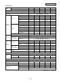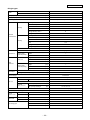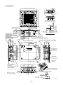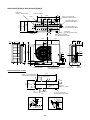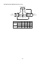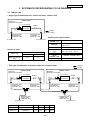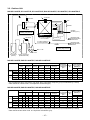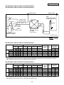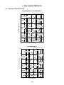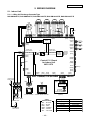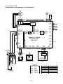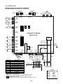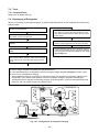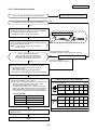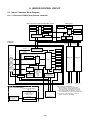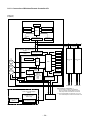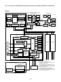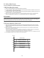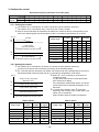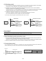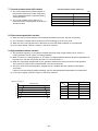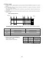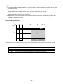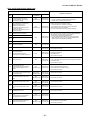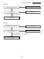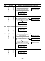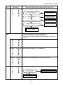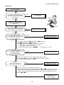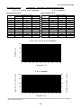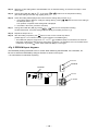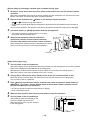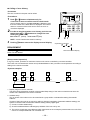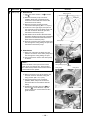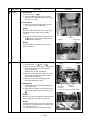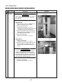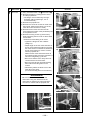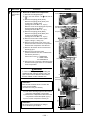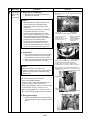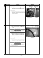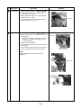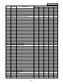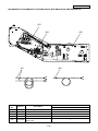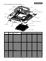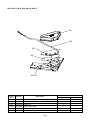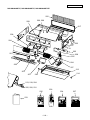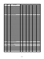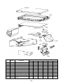
1
FILE NO. A07-003 Revised: Mar., 2008 Revised 2: Jun., 2008 SERVICE MANUAL AIR-CONDITIONER SPLIT TYPE INDOOR UNIT <DIGITAL INVERTER> RAV-SM564UT-E RAV-SM804UT-E RAV-SM1104UT-E RAV-SM1404UT-E RAV-SM1604UT-E RAV-SM404SDT-E RAV-SM454SDT-E RAV-SM564SDT-E OUTDOOR UNIT <SUPER DIGITAL INVERTER> RAV-SP404AT-E RAV-SP404ATZ-E RAV-SP404ATZG-E RAV-SP1104AT-E RAV-SP1104ATZ-E RAV-SP1104ATZG-E RAV-SP454AT-E RAV-SP454ATZ-E RAV-SP454ATZG-E RAV-SP1404AT-E RAV-SP1404ATZ-E RAV-SP1404ATZG-E R410A PRINTED IN JAPAN, Jun., 2008 ToMo Adoption of New Refrigerant This Air Conditioner is a new type which adopts a new refrigerant HFC (R410A) instead of the conventional refrigerant R22 in order to prevent destruction of the ozone layer. WARNING Cleaning of the air filter and other parts of the air filter involves dangerous work in high places, so be sure to have a service person do it. Do not attempt it yourself. The cleaning diagram for the air filter is there for the service person, and not for the customer. CONTENTS SAFETY CAUTION ............................................................................................ 4 1. SPECIFICATIONS ...................................................................................... 9 1-1. Indoor Unit........................................................................................................... 9 1-2. Outdoor Unit...................................................................................................... 25 1-3. Operation Characteristic Curve ....................................................................... 27 2. CONSTRUCTION VIEWS (EXTERNAL VIEWS)....................................... 29 2-1. Indoor Unit......................................................................................................... 29 2-2. Outdoor Unit...................................................................................................... 33 3. SYSTEMATIC REFRIGERATING CYCLE DIAGRAM .............................. 36 3-1. Indoor Unit......................................................................................................... 36 3-2. Outdoor Unit...................................................................................................... 37 4. FAN CHARACTERISTICS ........................................................................ 39 4-1. Slim Duct (Filter Attached) ............................................................................... 39 5. WIRING DIAGRAM ................................................................................... 40 5-1. Indoor Unit......................................................................................................... 40 5-2. Outdoor Unit...................................................................................................... 42 6. SPECIFICATIONS OF ELECTRICAL PARTS .......................................... 44 6-1. Indoor Unit......................................................................................................... 44 6-2. Outdoor Unit (Parts Ratings) ........................................................................... 45 6-3. Accessory Separate Sold Parts ....................................................................... 45 –2– 7. REFRIGERANT R410A ............................................................................ 46 7-1. 7-2. 7-3. 7-4. 7-5. 7-6. Safety During Installation / Servicing ............................................................. 46 Refrigerant Piping Installation ....................................................................... 46 Tools .................................................................................................................. 50 Recharging of Refrigerant................................................................................ 50 Brazing of Pipes................................................................................................ 51 Instructions for Re-use Piping of R22 or R407C ............................................ 53 8. INDOOR CONTROL CIRCUIT .................................................................. 58 8-1. 8-2. 8-3. 8-4. Indoor Controller Block Diagram..................................................................... 58 Control Specifications ...................................................................................... 61 Optional Connector Specifications of Indoor P.C. Board .............................. 74 Indoor Print Circuit Board ................................................................................ 75 9. CIRCUIT CONFIGURATION AND CONTROL SPECIFICATIONS ........... 76 9-1. Outdoor Controls .............................................................................................. 76 9-2. Outline of Main Controls .................................................................................. 78 10. TROUBLESHOOTING .............................................................................. 87 10-1. Summary of Troubleshooting ........................................................................... 87 10-2. Troubleshooting ................................................................................................ 89 11. REPLACEMENT OF SERVICE P.C. BOARD.......................................... 141 11-1. Indoort Unit ..................................................................................................... 141 11-2. Outdoor Unit.................................................................................................... 146 12. SETUP AT LOCAL SITE AND OTHERS ................................................ 147 12-1. 12-2. 12-3. 12-4. Indoor Unit....................................................................................................... Setup at Local Site / Others ........................................................................... How to Set up Central Control Address Number ......................................... Outdoor Unit.................................................................................................... 147 158 160 166 13. ADDRESS SETUP .................................................................................. 173 13-1. 13-2. 13-3. 13-4. 13-5. Address Setup Procedure .............................................................................. 173 Address Setup & Group Control .................................................................... 174 Remote Controller Wiring ............................................................................... 177 Address Setup (Manual setting from remote controller) ............................. 178 Confirmation of Indoor Unit No. Position ..................................................... 179 14. DETACHMENTS ..................................................................................... 181 14-1. Indoor Unit...................................................................................................... 181 14-2. Outdoor Unit.................................................................................................... 196 15. EXPLODED VIEWS AND PARTS LIST .................................................. 211 15-1. Indoor Unit....................................................................................................... 211 15-2. Outdoor Unit.................................................................................................... 219 –3– SAFETY CAUTION The important contents concerned to the safety are described on the product itself and on this Service Manual. Please read this Service Manual after understanding the described items thoroughly in the following contents (Indications/Illustrated marks), and keep them. [Explanation of indications] Indication Explanation DANGER Indicates contents assumed that an imminent danger causing a death or serious injury of the repair engineers and the third parties when an incorrect work has been executed. WARNING Indicates possibilities assumed that a danger causing a death or serious injury of the repair engineers, the third parties, and the users due to troubles of the product after work when an incorrect work has been executed. CAUTION Indicates contents assumed that an injury or property damage (∗) may be caused on the repair engineers, the third parties, and the users due to troubles of the product after work when an incorrect work has been executed. ∗ Property damage : Enlarged damage concerned to property, furniture, and domestic animal/pet [Explanation of illustrated marks] Mark Explanation Indicates prohibited items (Forbidden items to do) The sentences near an illustrated mark describe the concrete prohibited contents. Indicates mandatory items (Compulsory items to do) The sentences near an illustrated mark describe the concrete mandatory contents. Indicates cautions (Including danger/warning) The sentences or illustration near or in an illustrated mark describe the concrete cautious contents. [Confirmation of warning label on the main unit] Confirm that labels are indicated on the specified positions (Refer to the Parts disassembly diagram (Outdoor unit).) If removing the label during parts replace, stick it as the original. DANGER Turn off breaker. Execute discharge between terminals. Turn “OFF” the breaker before removing the front panel and cabinet, otherwise an electric shock is caused by high voltage resulted in a death or injury. During operation, a high voltage with 400V or higher of circuit (∗) at secondary circuit of the high-voltage transformer is applied. If touching a high voltage with the naked hands or body, an electric shock is caused even if using an electric insulator. ∗ : For details, refer to the electric wiring diagram. When removing the front panel or cabinet, execute short-circuit and discharge between high-voltage capacitor terminals. If discharge is not executed, an electric shock is caused by high voltage resulted in a death or injury. After turning off the breaker, high voltage also keeps to apply to the high-voltage capacitor. Do not turn on the breaker under condition that the front panel and cabinet are removed. An electric shock is caused by high voltage resulted in a death or injury. Prohibition –4– WARNING Check earth wires. Before troubleshooting or repair work, check the earth wire is connected to the earth terminals of the main unit, otherwise an electric shock is caused when a leak occurs. If the earth wire is not correctly connected, contact an electric engineer for rework. Do not modify the products. Do not also disassemble or modify the parts. It may cause a fire, electric shock or injury. Prohibition of modification. Use specified parts. Do not bring a child close to the equipment. ∗). For spare parts, use those specified (∗ If unspecified parts are used, a fire or electric shock may be caused. ∗: For details, refer to the parts list. Before troubleshooting or repair work, do not bring a third party (a child, etc.) except the repair engineers close to the equipment. It causes an injury with tools or disassembled parts. Please inform the users so that the third party (a child, etc.) does not approach the equipment. Connect the cut-off lead wires with crimp contact, etc, put the closed end side upward and then apply a water-cut method, otherwise a leak or production of fire is caused at the users’ side. Insulating measures No fire When repairing the refrigerating cycle, take the following measures. 1) Be attentive to fire around the cycle. When using a gas stove, etc, be sure to put out fire before work; otherwise the oil mixed with refrigerant gas may catch fire. 2) Do not use a welder in the closed room. When using it without ventilation, carbon monoxide poisoning may be caused. 3) Do not bring inflammables close to the refrigerant cycle, otherwise fire of the welder may catch the inflammables. Check the used refrigerant name and use tools and materials of the parts which match with it. For the products which use R410A refrigerant, the refrigerant name is indicated at a position on the outdoor unit where is easy to see. To prevent miss-charging, the route of the service port is changed from one of the former R22. For an air conditioner which uses R410A, never use other refrigerant than R410A. For an air conditioner which uses other refrigerant (R22, etc.), never use R410A. If different types of refrigerant are mixed, abnormal high pressure generates in the refrigerating cycle and an injury due to breakage may be caused. Refrigerant Do not charge refrigerant additionally. If charging refrigerant additionally when refrigerant gas leaks, the refrigerant composition in the refrigerating cycle changes resulted in change of air conditioner characteristics or refrigerant over the specified standard amount is charged and an abnormal high pressure is applied to the inside of the refrigerating cycle resulted in cause of breakage or injury. Therefore if the refrigerant gas leaks, recover the refrigerant in the air conditioner, execute vacuuming, and then newly recharge the specified amount of liquid refrigerant. In this time, never charge the refrigerant over the specified amount. When recharging the refrigerant in the refrigerating cycle, do not mix the refrigerant or air other than R410A into the specified refrigerant. If air or others is mixed with the refrigerant, abnormal high pressure generates in the refrigerating cycle resulted in cause of injury due to breakage. After installation work, check the refrigerant gas does not leak. If the refrigerant gas leaks in the room, poisonous gas generates when gas touches to fire such as fan heater, stove or cocking stove though the refrigerant gas itself is innocuous. Never recover the refrigerant into the outdoor unit. When the equipment is moved or repaired, be sure to recover the refrigerant with recovering device. The refrigerant cannot be recovered in the outdoor unit; otherwise a serious accident such as breakage or injury is caused. Assembly/Cabling After repair work, surely assemble the disassembled parts, and connect and lead the removed wires as before. Perform the work so that the cabinet or panel does not catch the inner wires. If incorrect assembly or incorrect wire connection was done, a disaster such as a leak or fire is caused at user’s side. –5– Revised 2: Jun., 2008 WARNING Insulator check Ventilation After the work has finished, be sure to use an insulation tester set (500V Megger) to check the resistance is 2MΩ or more between the charge section and the non-charge metal section (Earth position). If the resistance value is low, a disaster such as a leak or electric shock is caused at user’s side. When the refrigerant gas leaks during work, execute ventilation. If the refrigerant gas touches to a fire, poisonous gas generates. A case of leakage of the refrigerant and the closed room full with gas is dangerous because a shortage of oxygen occurs. Be sure to execute ventilation. When checking the circuit inevitably under condition of the power-ON, use rubber gloves and others not to touch to the charging section. If touching to the charging section, an electric shock may be caused. Be attentive to electric shock When the refrigerant gas leaks, find up the leaked position and repair it surely. If the leaked position cannot be found up and the repair work is interrupted, pump-down and tighten the service valve, otherwise the refrigerant gas may leak into the room. The poisonous gas generates when gas touches to fire such as fan heater, stove or cocking stove though the refrigerant gas itself is innocuous. Compulsion When installing equipment which includes a large amount of charged refrigerant such as a multi air conditioner in a sub-room, it is necessary that the density does not the limit even if the refrigerant leaks. If the refrigerant leaks and exceeds the limit density, an accident of shortage of oxygen is caused. For the installation/moving/reinstallation work, follow to the Installation Manual. If an incorrect installation is done, a trouble of the refrigerating cycle, water leak, electric shock or fire is caused. After repair work has finished, check there is no trouble. If check is not executed, a fire, electric shock or injury may be caused. For a check, turn off the power breaker. Check after repair After repair work (installation of front panel and cabinet) has finished, execute a test run to check there is no generation of smoke or abnormal sound. If check is not executed, a fire or an electric shock is caused. Before test run, install the front panel and cabinet. Check after reinstallation Check the following items after reinstallation. 1) The earth wire is correctly connected. 2) The power cord is not caught in the product. 3) There is no inclination or unsteadiness and the installation is stable. If check is not executed, a fire, an electric shock or an injury is caused. CAUTION Put on gloves Cooling check Be sure to put on the gloves (∗) and a long sleeved shirt: otherwise an injury may be caused with the parts, etc. (∗) Heavy gloves such as work gloves When the power was turned on, start to work after the equipment has been sufficiently cooled. As temperature of the compressor pipes and others became high due to cooling/heating operation, a burn may be caused. –6– • New Refrigerant (R410A) This air conditioner adopts a new HFC type refrigerant (R410A) which does not deplete the ozone layer. 1. Safety Caution Concerned to New Refrigerant The pressure of R410A is high 1.6 times of that of the former refrigerant (R22). Accompanied with change of refrigerant, the refrigerating oil has been also changed. Therefore, be sure that water, dust, the former refrigerant or the former refrigerating oil is not mixed into the refrigerating cycle of the air conditioner with new refrigerant during installation work or service work. If an incorrect work or incorrect service is performed, there is a possibility to cause a serious accident. Use the tools and materials exclusive to R410A to purpose a safe work. 2. Cautions on Installation/Service 1) Do not mix the other refrigerant or refrigerating oil. For the tools exclusive to R410A, shapes of all the joints including the service port differ from those of the former refrigerant in order to prevent mixture of them. 2) As the use pressure of the new refrigerant is high, use material thickness of the pipe and tools which are specified for R410A. 3) In the installation time, use clean pipe materials and work with great attention so that water and others do not mix in because pipes are affected by impurities such as water, oxide scales, oil, etc. Use the clean pipes. Be sure to brazing with flowing nitrogen gas. (Never use gas other than nitrogen gas.) 4) For the earth protection, use a vacuum pump for air purge. 5) R410A refrigerant is azeotropic mixture type refrigerant. Therefore use liquid type to charge the refrigerant. (If using gas for charging, composition of the refrigerant changes and then characteristics of the air conditioner change.) 3. Pipe Materials For the refrigerant pipes, copper pipe and joints are mainly used. It is necessary to select the most appropriate pipes to conform to the standard. Use clean material in which impurities adhere inside of pipe or joint to a minimum. 1) Copper pipe <Piping> The pipe thickness, flare finishing size, flare nut and others differ according to a refrigerant type. When using a long copper pipe for R410A, it is recommended to select “Copper or copper-base pipe without seam” and one with bonded oil amount 40mg/10m or less. Also do not use crushed, deformed, discolored (especially inside) pipes. (Impurities cause clogging of expansion valves and capillary tubes.) <Flare nut> Use the flare nuts which are attached to the air conditioner unit. 2) Joint The flare joint and socket joint are used for joints of the copper pipe. The joints are rarely used for installation of the air conditioner. However clear impurities when using them. –7– Revised 2: Jun., 2008 4. Tools 1. Required Tools for R410A Mixing of different types of oil may cause a trouble such as generation of sludge, clogging of capillary, etc. Accordingly, the tools to be used are classified into the following three types. 1) Tools exclusive for R410A (Those which cannot be used for conventional refrigerant (R22)) 2) Tools exclusive for R410A, but can be also used for conventional refrigerant (R22) 3) Tools commonly used for R410A and for conventional refrigerant (R22) The table below shows the tools exclusive for R410A and their interchangeability. Tools exclusive for R410A (The following tools for R410A are required.) Tools whose specifications are changed for R410A and their interchangeability R410A air conditioner installation No. Used tool Usage Conventional air conditioner installation Existence of new equipment for R410A Whether conventional equipment can be used Whether conventional equipment can be used Q Flare tool Pipe flaring Yes *(Note) Yes R Copper pipe gauge for adjusting projection margin Flaring by conventional flare tool Yes *(Note) *(Note) S Torque wrench Tightening of flare nut Yes No No T Gauge manifold U Yes No No Charge hose Evacuating, refrigerant charge, run check, etc. V Vacuum pump adapter Vacuum evacuating Yes No Yes W Electronic balance for refrigerant charging Refrigerant charge Yes Yes Yes X Refrigerant cylinder Refrigerant charge Yes No No Y Leakage detector Gas leakage check Yes No Yes (Note) When flaring is carried out for R410A using the conventional flare tools, adjustment of projection margin is necessary. For this adjustment, a copper pipe gauge, etc. are necessary. General tools (Conventional tools can be used.) In addition to the above exclusive tools, the following equipments which serve also for R22 are necessary as the general tools. 1) Vacuum pump. Use vacuum pump by attaching vacuum pump adapter. 7) Screwdriver (+, –) 2) Torque wrench 8) Spanner or Monkey wrench 3) Pipe cutter 9) Hole core drill 4) Reamer 10) Hexagon wrench (Opposite side 4mm) 5) Pipe bender 11) Tape measure 6) Level vial 12) Metal saw Also prepare the following equipments for other installation method and run check. 1) Clamp meter 3) Insulation resistance tester (Megger) 2) Thermometer 4) Electroscope –8– Revised 2: Jun., 2008 1. SPECIFICATIONS 1-1. Indoor Unit 1-1-1. 4-Way Air Discharge Cassette Type <Single type> Indoor unit RAV-SM 564UT-E 804UT-E 1104UT-E Outdoor unit RAV-SP 562AT(Z)(ZG)-E 802AT(Z)(ZG)-E 1404UT-E Model 1104AT(Z)(ZG)-E 1404AT(Z)(ZG)-E Cooling capacity (kW) 5.3 7.1 10.0 12.5 Heating capacity (kW) 5.6 8.0 11.2 14.0 Power supply 1 phase 230V (220 – 240V) 50Hz Running current (A) 7.17 – 6.57 8.95 – 8.21 10.36 – 9.49 14.66 – 13.44 1.53 1.93 2.21 3.16 97 98 97 98 3.46 3.68 4.52 3.96 Energy efficiency class ∗ A A A A Energy rating ∗∗ — — — — 5.62 – 5.15 9.42 – 8.63 10.96 – 10.05 14.89 – 13.65 1.20 2.03 2.34 3.21 97 98 97 98 Power consumption (kW) Power factor (%) Cooling EER Electrical characteristics Running current (A) Power consumption (kW) Power factor (%) Heating COP 4.67 3.94 4.79 4.36 Energy efficiency class ∗ A A A A Energy rating ∗∗ — — — — 15.33 15.33 20.50 20.50 Maximum current (A) Main unit Appearance Ceiling panel (Sold separately) Zinc hot dipping steel plate Model RBC-U31PG (W, WS)-E, RBC-U31PGS (W, WS)-E Panel color W: Moon-white (2.5GY 9.0/0.5), WS: Stripe-white (2.5GY 9.0/0.5, (Gray: 8B 3/0.3)) Height (mm) 256 256 319 319 Width (mm) 840 840 840 840 Depth (mm) 840 840 840 840 Height (mm) 30 30 30 30 Width (mm) 950 950 950 950 Depth (mm) 950 950 950 950 Main unit (kg) 20 20 24 24 Ceiling panel (Sold separately) (kg) 4.2 4.2 4.2 4.2 Main unit Outer dimension Ceiling panel (Sold separately) Total weight Heat exchanger Finned tube Fan Fan unit Standard air flow Turbo fan H/M/L Motor (m³/min.) (W) 17.5/14.5/13.0 20.5/16.0/13.5 33.5/24.0/19.5 35.0/24.0/20.5 14 20 68 72 Air filter Standard filter attached (Long life filter) Controller (Sold separately) RBC-AMT32E, AMS41E, AS21E2, AX31U (W)-E Sound pressure level H/M/L (dB•A) 32 / 29 / 28 35 / 31 / 28 43 / 38 / 33 44 / 38 / 34 Sound power level H/M/L (dB•A) 47 / 44 / 43 50 / 46 / 43 58 / 53 / 48 59 / 53 / 49 Gas side (mm) 12.7 15.9 15.9 15.9 Liquid side (mm) 6.4 9.5 9.5 9.5 Drain port (mm) Connecting pipe VP25 ∗ : IEC standard, ∗∗ : AS standard –9– Revised 2: Jun., 2008 <Single type> Indoor unit RAV- SM564UT-E SM804UT-E SM1104UT-E SM1404UT-E SM1604UT-E Outdoor unit RAV- SM563AT-E SM803AT-E SM1103AT-E SM1403AT-E SM1603AT-E Cooling capacity (kW) 5.3 6.7 10.0 12.0 14.0 Heating capacity (kW) 5.6 8.0 11.2 14.0 16.0 7.89 – 7.24 9.97 – 9.12 1.65 2.09 3.11 3.74 4.49 95 95 97 96 95 3.21 3.21 3.22 3.21 3.12 Energy efficiency class ∗ A A A A B Energy rating ∗∗ — — — — — 6.89 – 6.32 10.83 – 9.90 1.44 2.21 2.93 3.80 4.43 95 93 99 98 95 3.89 3.62 3.82 3.68 3.61 Energy efficiency class ∗ A A A A A Energy rating ∗∗ — — — — — 15.33 15.33 20.50 20.50 32.0 Model Power supply 1 phase 230V (220 – 240V) 50Hz Running current (A) Power consumption (kW) Cooling Power factor (%) EER Electrical characteristics Running current (A) Power consumption (kW) Heating Power factor (%) COP Maximum current (A) Main unit Appearance Ceiling panel (Sold separately) Main unit Outer dimension Zinc hot dipping steel plate Model RBC-U31PG (W, WS)-E, RBC-U31PGS (W, WS)-E Panel color W: Moon-white (2.5GY 9.0/0.5), WS: Stripe-white (2.5GY 9.0/0.5, (Gray: 8B 3/0.3)) Height (mm) 256 256 319 319 319 Width (mm) 840 840 840 840 840 Depth (mm) 840 840 840 840 840 (mm) 30 30 30 30 30 Width (mm) 950 950 950 950 950 Depth (mm) 950 950 950 950 950 Main unit (kg) 20 20 24 24 24 Ceiling panel (Sold separately) (kg) 4.2 4.2 4.2 4.2 4.2 Heat exchanger Finned tube Fan Fan unit 13.38 – 12.38 17.88 – 15.87 21.20 – 19.43 Height Ceiling panel (Sold separately) Total weight 14.61 – 13.40 17.62 – 16.14 21.48 – 19.69 Standard air flow Turbo fan H/M/L Motor (m³/min.) 17.5/14.5/13.0 20.5/16.0/13.5 33.5/24.0/19.5 35.0/24.0/20.5 35.5/25.0/21.0 (W) 14 Air filter 20 68 72 72 Standard filter attached (Long life filter) Controller (Sold separately) RBC-AMT32E, AMS41E, AS21E2, AX31U (W)-E Sound pressure level H/M/L (dB•A) 32 / 29 / 28 35 / 31 / 28 43 / 38 / 33 44 / 38 / 34 45 / 40 / 36 Sound power level H/M/L (dB•A) 47 / 44 / 43 50 / 46 / 43 58 / 53 / 48 59 / 53 / 49 60 / 55 / 51 Gas side (mm) 12.7 15.9 15.9 15.9 15.9 Liquid side (mm) 6.4 9.5 9.5 9.5 9.5 Drain port (mm) Connecting pipe VP25 ∗ : IEC standard, ∗∗ : AS standard – 10 – Revised 2: Jun., 2008 <Twin type> Indoor unit 1 RAV- SM564UT-E SM804UT-E Indoor unit 2 RAV- SM564UT-E SM804UT-E Outdoor unit RAV- SP1104AT(Z)(ZG)-E SP1404AT(Z)(ZG)-E Cooling capacity (kW) 10.0 12.5 Heating capacity (kW) 11.2 14.0 Model Indoor unit Power supply 1 phase 230V (220 – 240V) 50Hz Running current (A) Power consumption Cooling Power factor 10.36 – 9.49 14.66 – 13.44 (kW) 2.21 3.16 (%) 97 98 4.52 3.96 A A 10.96 – 10.05 14.89 – 13.65 (kW) 2.34 3.21 (%) 97 98 4.79 4.36 A A EER Energy efficiency class ∗ Electrical characteristics Running current (A) Power consumption Heating Power factor COP Energy efficiency class ∗ Fan Fan unit Turbo fan Standard air flow H/M/L Motor (m³/min.) (W) 17.5 / 14.5 / 13.0 20.5 / 16.0 / 13.5 14 20 Sound pressure level H/M/L (dB•A) 32 / 29 / 28 35 / 31 / 28 Sound power level H/M/L (dB•A) 47 / 44 / 43 50 / 46 / 43 Outdoor unit Power supply Refrigerant pipe 1 phase 230V (220 – 240V) 50Hz Standard length (m) 7.5 7.5 Min. length (m) 3 3 Max. total length (m) 50 50 Refrigerant charging amount (Charge-less up to 30m) Height difference 40g/m (31m to 50m) Outdoor lower (m) 30 30 Outdoor higher (m) 30 30 Fan Fan unit Propeller fan Standard air flow volume Motor (m³/min.) (W) 101 103 100 + 100 100 + 100 Main (mm) 15.9 15.9 Sub (mm) 12.7 15.9 Main (mm) 9.5 9.5 Sub (mm) 6.4 9.5 Gas side Connecting pipe Liquid side Sound pressure level Cooling/Heating (dB•A) 49 / 50 51 / 52 Sound power level Cooling/Heating (dB•A) 66 / 67 68 / 69 ∗ : IEC standard – 11 – Revised 2: Jun., 2008 <Twin type> Indoor unit 1 RAV- SM564UT-E SM804UT-E SM804UT-E Indoor unit 2 RAV- SM564UT-E SM804UT-E SM804UT-E Outdoor unit RAV- SM1103AT-E SM1403AT-E SM1603AT-E Cooling capacity (kW) 10.0 12.5 14.0 Heating capacity (kW) 11.2 14.0 16.0 Model Indoor unit Power supply 1 phase 230V (220 – 240V) 50Hz Running current (A) Power consumption Cooling Power factor 14.59 – 13.38 19.17 – 17.57 21.48 – 19.69 (kW) 3.11 4.09 4.49 (%) 98 97 95 3.22 3.06 3.12 A (B) (B) 13.36 – 12.36 18.74 – 17.18 21.20 – 19.43 (kW) 2.93 4.00 4.43 (%) 99 97 95 3.82 3.50 3.61 A (B) (A) EER Energy efficiency class ∗ Electrical characteristics Running current (A) Power consumption Heating Power factor COP Energy efficiency class ∗ Fan Fan unit Turbo fan Standard air flow H/M/L Motor (m³/min.) 17.5 / 14.5 / 13.0 20.5 / 16.0 / 13.5 20.5 / 16.0 / 13.5 14 20 20 (W) Sound pressure level H/M/L (dB•A) 32 / 29 / 28 35 / 31 / 28 35 / 31 / 28 Sound power level H/M/L (dB•A) 47 / 44 / 43 50 / 46 / 43 50 / 46 / 43 Outdoor unit Power supply Refrigerant pipe 1 phase 230V (220 – 240V) 50Hz Standard length (m) 7.5 7.5 7.5 Min. length (m) 5 5 5 Max. total length (m) 50 50 50 Refrigerant charging amount (Charge-less up to 30m) Height difference 40g/m (31m to 50m) Outdoor lower (m) 30 30 30 Outdoor higher (m) 30 30 30 Fan Fan unit Propeller fan Standard air flow volume Motor (m³/min.) 75 75 103 (W) 63 100 100 + 100 Main (mm) 15.9 15.9 15.9 Sub (mm) 12.7 15.9 15.9 Main (mm) 9.5 9.5 9.5 Sub (mm) 6.4 9.5 9.5 Gas side Connecting pipe Liquid side Sound pressure level Cooling/Heating (dB•A) 53 / 54 54 / 54 51 / 53 Sound power level Cooling/Heating (dB•A) 70 / 71 71 / 71 68 / 70 ∗ : IEC standard – 12 – Revised 2: Jun., 2008 1-1-2. Concealed Duct Type <Single type> Model Indoor unit RAV-SM 562BT-E 802BT-E Outdoor unit RAV-SP 1102BT-E 1402BT-E 562AT(Z)(ZG)-E 802AT(Z)(ZG)-E Cooling capacity (kW) 5.0 7.1 10.0 12.5 Heating capacity (kW) 5.6 8.0 11.2 14.0 Power supply 1 phase 230V (220 – 240V) 50Hz Running current (A) Power consumption (kW) Cooling Power factor (%) EER Electrical characteristics 9.74 – 8.93 13.78 – 12.63 17.76 – 16.28 1.39 2.10 2.94 3.83 97 98 97 98 3.60 3.38 3.40 3.26 A A A A Energy rating ∗∗ — — — — 7.26 – 6.66 9.74 – 8.93 12.98 – 11.90 15.82 – 14.50 1.55 2.41 2.77 3.41 97 94 97 98 3.61 3.32 4.04 4.11 Running current Heating 6.51 – 5.97 Energy efficiency class ∗ (A) Power consumption (kW) Power factor (%) COP Energy efficiency class ∗ A A A A Energy rating ∗∗ — — — — 15.86 16.30 21.73 22.13 Maximum current (A) Main unit Appearance Ceiling panel (Sold separately) Main unit Outer dimension Ceiling panel (Sold separately) Total weight Zinc hot dipping steel plate Model — Panel color — Height (mm) 320 320 320 320 Width (mm) 700 1000 1350 1350 Depth (mm) 800 800 800 800 Height (mm) — — — — Width (mm) — — — — Depth (mm) — — — — Main unit (kg) 30 39 54 54 Ceiling panel (Sold separately) (kg) — — — — Heat exchanger Finned tube Fan Standard air flow Fan unit 1104AT(Z)(ZG)-E 1404AT(Z)(ZG)-E Centrifugal H/M/L (m³/min.) Motor External static pressure (W) Standard (at shipment) (Pa) Set up for tap exchange (Pa) Air filter (Sold separately) TCB- 13.0/11.9/9.8 19.0/16.2/13.3 27.0/23.0/18.9 33.0/28.0/23.1 120 120 120 120 40 20/40/70/100 UFM21BE UFM61BE Controller (Sold separately) 20/40/65/90 UFM11BFCE UFM31BE UFM51BFCE UFM71BE UFM21BFCE UFM41BE UFM61BFCE UFM81BE RBC-AMT31E, AMS41E, AS21E2, AX21U(W)-E2 Sound pressure level H/M/L (dB•A) 40 / 37 / 33 40 / 37 / 34 42 / 39 / 36 44 / 41 / 38 Sound power level H/M/L Connecting pipe (dB•A) 55 / 52 / 48 55 / 52 / 49 57 / 54 / 51 59 / 56 / 53 Gas side (mm) 12.7 15.9 15.9 15.9 Liquid side (mm) 6.4 9.5 9.5 9.5 Drain port (mm) VP25 ∗ : IEC standard, ∗∗ : AS standard – 13 – Revised 2: Jun., 2008 <Twin type> Indoor unit 1 RAV- SM562BT-E SM802BT-E Indoor unit 2 RAV- SM562BT-E SM802BT-E Outdoor unit RAV- SP1104AT(Z)(ZG)-E SP1404AT(Z)(ZG)-E Cooling capacity (kW) 10.0 12.5 Heating capacity (kW) 11.2 14.0 Model Indoor unit Power supply 1 phase 230V (220 – 240V) 50Hz Running current (A) Power consumption Cooling Power factor 13.78 – 12.63 17.76 – 16.28 (kW) 2.94 3.83 (%) 97 98 3.4 3.26 A A 12.98 – 11.90 15.82 – 14.50 (kW) 2.77 3.41 (%) 97 98 4.04 4.11 A A EER Energy efficiency class ∗ Electrical characteristics Running current (A) Power consumption Heating Power factor COP Energy efficiency class ∗ Fan Fan unit Centrifugal Standard air flow H/M/L Motor (m³/min.) (W) 13.0 / 11.9 / 9.8 19.0 / 16.2 / 13.3 120 120 Sound pressure level H/M/L (dB•A) 40 / 37 / 33 40 / 37 / 34 Sound power level H/M/L (dB•A) 55 / 52 / 48 55 / 52 / 49 Outdoor unit Power supply Refrigerant pipe 1 phase 230V (220 – 240V) 50Hz Standard length (m) 7.5 7.5 Min. length (m) 3 3 Max. total length (m) 50 50 Refrigerant charging amount (Charge-less up to 30m) Height difference 40g/m (31m to 50m) Outdoor lower (m) 30 30 Outdoor higher (m) 30 30 Fan Fan unit Propeller fan Standard air flow volume Motor (m³/min.) (W) 101 103 100 + 100 100 + 100 Main (mm) 15.9 15.9 Sub (mm) 12.7 15.9 Main (mm) 9.5 9.5 Sub (mm) 6.4 9.5 Gas side Connecting pipe Liquid side Sound pressure level Cooling/Heating (dB•A) 49 / 50 51 / 52 Sound power level Cooling/Heating (dB•A) 66 / 67 68 / 69 ∗ : IEC standard – 14 – Revised 2: Jun., 2008 1-1-3. Under Ceiling Type <Single type> Indoor unit RAV-SM 562CT-E 802CT-E 1102CT-E Outdoor unit RAV-SP 562AT(Z)(ZG)-E 802AT(Z)(ZG)-E 1402CT-E Model 1104AT(Z)(ZG)-E 1404AT(Z)(ZG)-E Cooling capacity (kW) 5.0 7.1 10.0 12.5 Heating capacity (kW) 5.6 8.0 11.2 14.0 Power supply 1 phase 230V (220 – 240V) 50Hz Running current (A) 6.61 – 6.06 9.47 – 8.93 12.51 – 11.47 17.30 – 15.86 1.41 2.1 2.67 3.73 97 98 97 98 3.55 3.38 3.75 3.35 Energy efficiency class ∗ A A A A Energy rating ∗∗ — — — — 7.03 – 6.44 10.20 – 9.35 12.28 – 11.25 16.93 – 15.52 1.50 2.20 2.62 3.65 97 98 97 98 3.73 3.64 4.27 3.84 Energy efficiency class ∗ A A A A Energy rating ∗∗ — — — — 15.48 15.90 21.35 21.35 Power consumption (kW) Power factor (%) Cooling EER Electrical characteristics Running current (A) Power consumption (kW) Power factor (%) Heating COP Maximum current (A) Main unit Appearance Ceiling panel (Sold separately) Shine white Model — Panel color — Height (mm) 210 210 210 210 Width (mm) 910 1180 1595 1595 Depth (mm) 680 680 680 680 Height (mm) — — — — Width (mm) — — — — Depth (mm) — — — — Main unit (kg) 21 25 33 33 Ceiling panel (Sold separately) (kg) — — — — Main unit Outer dimension Ceiling panel (Sold separately) Total weight Heat exchanger Finned tube Fan Fan unit Standard air flow Centrifugal H/M/L Motor (m³/min.) (W) 13.0/11.2/10.0 18.5/16.7/14.6 27.5/24.0/21.2 30.0/26.0/23.1 60 60 120 120 Air filter Attached main unit Controller (Sold separately) RBC-AMT31E, AMS41E, AS21E2, TCB-SC642TLE2, AX21UCE2 Sound pressure level H/M/L (dB•A) 36 / 33 / 30 38 / 36 / 33 41 / 38 / 36 43 / 40 / 37 Sound power level H/M/L (dB•A) 51 / 48 / 45 53 / 51 / 48 56 / 53 / 50 58 / 55 / 52 Gas side (mm) 12.7 15.9 15.9 15.9 Liquid side (mm) 6.4 9.5 9.5 9.5 Drain port (mm) Connecting pipe VP25 ∗ : IEC standard, ∗∗ : AS standard – 15 – Revised 2: Jun., 2008 <Twin type> Indoor unit 1 RAV- SM562CT-E SM802CT-E Indoor unit 2 RAV- SM562CT-E SM802CT-E Outdoor unit RAV- SP1104AT(Z)(ZG)-E SP1404A(Z)(ZG)-E Cooling capacity (kW) 10.0 12.5 Heating capacity (kW) 11.2 14.0 Model Indoor unit Power supply 1 phase 230V (220 – 240V) 50Hz Running current (A) Power consumption Cooling Power factor 12.51 – 11.47 17.30 – 15.86 (kW) 2.67 3.73 (%) 97 98 3.75 3.35 A A 12.28 – 11.25 16.93 – 15.52 (kW) 2.62 3.65 (%) 97 98 4.27 3.84 A A EER Energy efficiency class ∗ Electrical characteristics Running current (A) Power consumption Heating Power factor COP Energy efficiency class ∗ Fan Fan unit Centrifugal Standard air flow H/M/L Motor (m³/min.) (W) 13.0 / 11.2 / 10.0 18.5 / 16.7 / 14.6 60 60 Sound pressure level H/M/L (dB•A) 36 / 33 / 30 38 / 36 / 33 Sound power level H/M/L (dB•A) 51 / 48 / 45 53 / 51 / 48 Outdoor unit Power supply Refrigerant pipe 1 phase 230V (220 – 240V) 50Hz Standard length (m) 7.5 7.5 Min. length (m) 3 3 Max. total length (m) 50 50 Refrigerant charging amount (Charge-less up to 30m) Height difference 40g/m (31m to 50m) Outdoor lower (m) 30 30 Outdoor higher (m) 30 30 Fan Fan unit Propeller fan Standard air flow volume Motor (m³/min.) (W) 101 103 100 + 100 100 + 100 Main (mm) 15.9 15.9 Sub (mm) 12.7 15.9 Main (mm) 9.5 9.5 Sub (mm) 6.4 9.5 Gas side Connecting pipe Liquid side Sound pressure level Cooling/Heating (dB•A) 49 / 50 51 / 52 Sound power level Cooling/Heating (dB•A) 66 / 67 68 / 69 ∗ : IEC standard – 16 – Revised 2: Jun., 2008 1-1-4. High Wall Type <Single type> Indoor unit RAV- SM562KRT-E SM802KRT-E Outdoor unit RAV- SP562AT(Z)(ZG)-E SP802AT(Z)(ZG)-E Cooling capacity (kW) 5.0 6.9 Heating capacity (kW) 5.6 8.0 Model Power supply 1 phase 230V (220 – 240V) 50Hz Running current (A) 8.33 – 7.63 13.15 – 12.05 (kW) 1.39 2.4 (%) 95 94 3.60 2.88 Energy efficiency class ∗ A C Energy rating ∗∗ — — 8.14 – 7.46 12.91 – 11.84 (kW) 1.55 2.4 (%) 95 94 3.61 3.33 Energy efficiency class ∗ A C Energy rating ∗∗ — — 15.34 15.47 Power consumption Power factor Cooling EER Electrical characteristics Running current (A) Power consumption Power factor Heating COP Maximum current (A) Main unit Appearance Ceiling panel (Sold separately) Pure white Model — Panel color — Height (mm) 298 298 Width (mm) 998 998 Depth (mm) 221 221 Height (mm) — — Width (mm) — — Depth (mm) — — Main unit (kg) 12 12 Ceiling panel (Sold separately) (kg) — — Main unit Outer dimension Ceiling panel (Sold separately) Total weight Heat exchanger Finned tube Fan Fan unit Standard air flow H/M/L Motor (m³/min.) (W) Cross flow fan Cross flow fan 14.0 / 12.5 / 10.7 18.5 / 14.6 / 12.2 30 30 Air filter Attached main unit RBC-AMT31E, AMS41E, AS21E2, TCB-SC642TLE2, AX21UCE2 (FCU comes with WH-H2UE) Controller (Sold separately) Sound pressure level H/M/L (dB•A) 39 / 36 / 33 45 / 41 / 36 Sound power level H/M/L (dB•A) 54 / 51 / 48 60 / 56 / 51 Gas side (mm) 12.7 15.9 Liquid side (mm) 6.4 9.5 Drain port (mm) Connecting pipe VP16 ∗ : IEC standard, ∗∗ : AS standard – 17 – Revised 2: Jun., 2008 <Twin type> Indoor unit 1 RAV- SM562KRT-E SM802KRT-E Indoor unit 2 RAV- SM562KRT-E SM802KRT-E Outdoor unit RAV- SP1104AT(Z)(ZG)-E SP1404AT(Z)(ZG)-E Cooling capacity (kW) 10.0 12.3 Heating capacity (kW) 11.2 14.0 Model Indoor unit Power supply 1 phase 230V (220 – 240V) 50Hz Running current (A) Power consumption Cooling Power factor 12.98 – 11.90 18.00 – 16.50 (kW) 2.77 3.88 (%) 97 98 3.61 3.17 A B 13.12 – 12.03 17.76 – 16.28 (kW) 2.80 3.83 (%) 97 98 4.00 3.66 A A EER Energy efficiency class ∗ Electrical characteristics Running current (A) Power consumption Heating Power factor COP Energy efficiency class ∗ Fan Fan unit Cross flow fan Standard air flow H/M/L Motor (m³/min.) (W) 14.0 / 12.5 / 10.7 18.5 / 14.6 / 12.2 30 30 Sound pressure level H/M/L (dB•A) 39 / 36 / 33 45 / 41 / 36 Sound power level H/M/L (dB•A) 54 / 51 / 48 60 / 56 / 51 Outdoor unit Power supply Refrigerant pipe 1 phase 230V (220 – 240V) 50Hz Standard length (m) 7.5 7.5 Min. length (m) 3 3 Max. total length (m) 50 50 Refrigerant charging amount (Charge-less up to 30m) Height difference 40g/m (31m to 50m) Outdoor lower (m) 30 30 Outdoor higher (m) 30 30 Fan Fan unit Propeller fan Standard air flow volume Motor (m³/min.) (W) 101 103 100 + 100 100 + 100 Main (mm) 15.9 15.9 Sub (mm) 12.7 15.9 Main (mm) 9.5 9.5 Sub (mm) 6.4 9.5 Gas side Connecting pipe Liquid side Sound pressure level Cooling/Heating (dB•A) 49 / 50 51 / 52 Sound power level Cooling/Heating (dB•A) 66 / 67 68 / 69 ∗ : IEC standard – 18 – 1-1-5. Compact 4-Way Cassette (600 × 600) Type <Single type> RAV-SM562MUT-E Indoor unit Model Outdoor unit RAV-SP562AT(Z)(ZG)-E Cooling capacity (kW) 5.0 Heating capacity (kW) 5.6 Power supply 1 phase 230V (220 – 240V) 50Hz Running current (A) Power consumption Power factor 6.6 – 7.15 (kW) 1.53 (%) 97 Cooling EER 3.27 Energy efficiency class A Energy rating Electrical characteristics 4.5 Running current (A) Power consumption Power factor 6.62 – 7.21 (kW) 1.54 (%) 97 Heating COP 3.64 Energy efficiency class A Energy rating Maximum current 4.5 (A) Main unit Appearance Ceiling panel (Sold separately) 15.53 Zinc hot dipping steel plate Model RBC-UM11PG(W)-E Moon-white (Muncel 2.5GY 9.0 / 0.5) Panel color Height (mm) 268 Width (mm) 575 Depth (mm) 575 Height (mm) 27 Width (mm) 700 Depth (mm) 700 Main unit (kg) 17 Ceiling panel (Sold separately) (kg) 3 Main unit Outer dimension Ceiling panel (Sold separately) Total weight Heat exchanger Finned tube Fan Fan unit Standard air flow Turbo fan H/M/L (m³/min.) Motor (W) Air filter 13.3 / 11.2 / 9.1 60 — Controller (Sold separately) As per enclosure Sound pressure level H/M/L (dB•A) 43 / 39 / 34 Sound power level H/M/L (dB•A) 58 / 54 / 49 Connecting pipe Gas side (mm) 12.7 Liquid side (mm) 6.4 Drain port (mm) VP25 – 19 – Revised 2: Jun., 2008 <Twin type> Indoor unit 1 RAV- SM562MUT-E Indoor unit 2 RAV- SM562MUT-E Outdoor unit RAV- SP1104AT(Z)(ZG)-E Cooling capacity (kW) 10.0 Heating capacity (kW) 11.2 Model Indoor unit Power supply 1 phase 230V (220 – 240V) 50Hz Running current (A) Power consumption Cooling Power factor (kW) 2.67 (%) 97 EER 3.75 Energy efficiency class ∗ Electrical characteristics Running current A (A) Power consumption Heating Power factor 2.67 (%) 97 4.19 Energy efficiency class ∗ A Fan Standard air flow 12.51 – 11.47 (kW) COP Fan unit 12.51 – 11.47 Turbo fan H/M/L (m³/min.) Motor (W) 13.3 / 11.2 / 9.1 60 Sound pressure level H/M/L (dB•A) 43 / 39 / 34 Sound power level H/M/L (dB•A) 58 / 54 / 49 Outdoor unit Power supply 1 phase 230V (220 – 240V) 50Hz Standard length (m) 7.5 Min. length (m) 3 Max. total length (m) 50 Refrigerant pipe Refrigerant charging amount (Charge-less up to 30m) 40g/m (31m to 50m) Outdoor lower (m) 30 Outdoor higher (m) 30 Height difference Fan Fan unit Propeller fan Standard air flow volume (m³/min.) Motor (W) 101 100 + 100 Main (mm) 15.9 Sub (mm) 12.7 Main (mm) 9.5 Sub (mm) 6.4 Gas side Connecting pipe Liquid side Sound pressure level Cooling/Heating (dB•A) 49 / 50 Sound power level Cooling/Heating (dB•A) 66 / 67 ∗ : IEC standard – 20 – Revised 2: Jun., 2008 1-1-6. Slim Duct Type <Single type> Model Indoor unit RAV-SM 404SDT-E 454SDT-E 564SDT-E Outdoor unit RAV-SP 404AT(Z)(ZG)-E 454AT(Z)(ZG)-E 562AT(Z)(ZG)-E 4.0 5.0 4.5 5.6 Cooling capacity (kW) 3.6 Heating capacity (kW) 4.0 Power supply 1 phase 230V (220 – 240V) 50Hz Running current Power consumption Cooling Power factor (A) 5.20 – 4.77 5.87 – 5.38 7.26 – 6.66 (kW) 1.03 1.20 1.55 (%) 90 93 97 3.50 3.33 3.23 A A A EER Energy efficiency class ∗ Energy rating ∗∗ Electrical characteristics Running current Power consumption Heating Power factor 5.0 4.5 4.0 4.94 – 4.53 5.62 – 5.15 6.75 – 6.19 (kW) 1.00 1.15 1.44 (%) 92 93 97 4.00 3.91 3.89 A A A 5.5 5.0 5.0 15.00 15.00 (A) COP Energy efficiency class ∗ Energy rating ∗∗ Maximum current (A) 15.00 Main unit Appearance Ceiling panel (Sold separately) Model — Panel color — Height (mm) 210 210 210 Width (mm) 845 845 845 Depth (mm) 645 645 645 Height (mm) — — — Width (mm) — — — Depth (mm) — — — Main unit (kg) 22 22 22 Ceiling panel (Sold separately) (kg) — — — Main unit Outer dimension Ceiling panel (Sold separately) Total weight Zinc hot dipping steel plate Heat exchanger Finned tube Fan Standard air flow Fan unit Centrifugal H/M/L Motor External static pressure (m³/min.) (W) 11.5 / 10.0 / 8.7 60 11.5 / 10.0 / 8.7 13.0 / 11.3 / 9.7 60 60 Standard (at shipment) (Pa) 10 Set up for tap exchange (Pa) 10 / 20 / 35 / 50 Air filter Standard filter attached (Long life filter) Controller (Sold separately) RBC-AMT32E, AMS41E, AS21E2 Sound pressure level Under air inlet H/M/L (dB•A) 39 / 36 / 33 39 / 36 / 33 45 / 40 / 36 Back air inlet H/M/L (dB•A) 30 / 28 / 26 30 / 28 / 26 33 / 31 / 28 Sound power level Under air inlet H/M/L (dB•A) 54 / 51 / 48 54 / 51 / 48 60 / 55 / 51 Back air inlet H/M/L (dB•A) 45 / 43 / 41 45 / 43 / 41 48 / 46 / 43 Gas side (mm) 12.7 12.7 12.7 Liquid side (mm) 6.4 6.4 6.4 Drain port (mm) Connecting pipe VP25 ∗ : IEC standard, ∗∗ : AS standard – 21 – Revised 2: Jun., 2008 <Single type> Model Indoor unit RAV-SM 564SDT-E Outdoor unit RAV-SM 563AT-E Cooling capacity (kW) 5.0 Heating capacity (kW) 5.6 Power supply 1 phase 230V (220 – 240V) 50Hz Running current Power consumption Cooling Power factor (A) (kW) 1.66 (%) 95 EER 3.01 Energy efficiency class ∗ B Energy rating ∗∗ Electrical characteristics Running current Power consumption Heating Power factor 3.5 (A) 1.59 (%) 95 3.52 Energy efficiency class ∗ B Energy rating ∗∗ 4.0 (A) Main unit Appearance Ceiling panel (Sold separately) Model — Panel color — (mm) 210 Width (mm) 845 Depth (mm) 645 Height (mm) — Width (mm) — Depth (mm) — Main unit (kg) 22 Ceiling panel (Sold separately) (kg) — Outer dimension Ceiling panel (Sold separately) Heat exchanger Finned tube Fan Standard air flow Fan unit 15.00 Zinc hot dipping steel plate Height Main unit Total weight 7.61 – 6.97 (kW) COP Maximum current 7.94 – 7.28 Centrifugal H/M/L Motor External static pressure (m³/min.) 13.0 / 11.3 / 9.7 (W) 60 Standard (at shipment) (Pa) 10 Set up for tap exchange (Pa) 10 / 20 / 35 / 50 Air filter Standard filter attached (Long life filter) Controller (Sold separately) RBC-AMT32E, AMS41E, AS21E2 Sound pressure level Under air inlet H/M/L (dB•A) 45 / 40 / 36 Back air inlet H/M/L (dB•A) 33 / 31 / 28 Sound power level Under air inlet H/M/L (dB•A) 60 / 55 / 51 Back air inlet H/M/L (dB•A) 48 / 46 / 43 Gas side (mm) 12.7 Liquid side (mm) 6.4 Drain port (mm) VP25 Connecting pipe ∗ : IEC standard, ∗∗ : AS standard – 22 – Revised 2: Jun., 2008 <Twin type> Model Indoor unit 1 RAV-SM 564SDT-E 564SDT-E Indoor unit 2 RAV-SM 564SDT-E 564SDT-E Outdoor unit RAV-SP 1104AT(Z)(ZG)-E 1102AT(Z)(ZG)-E Cooling capacity (kW) 10.0 10.0 Heating capacity (kW) 11.2 11.2 Indoor unit Power supply 1 phase 230V (220 – 240V) 50Hz Running current (A) Power consumption Cooling Power factor 12.98 –11.90 11.72 – 10.74 (kW) 2.77 2.50 (%) 97 97 3.61 4.00 A A 12.51 – 11.47 11.95 – 10.95 (kW) 2.67 2.55 (%) 97 97 4.19 4.39 A A EER Energy efficiency class ∗ Electrical characteristics Running current (A) Power consumption Heating Power factor COP Energy efficiency class ∗ Fan Fan unit Standard air flow Centrifugal H/M/L (m³/min.) Motor Sound pressure level Sound power level (W) 13.0 / 11.3 / 9.7 13.0 / 11.3 / 9.7 60 60 Under air inlet H/M/L (dB•A) 45 / 40 / 36 45 / 40 / 36 Back air inlet H/M/L (dB•A) 33 / 31 / 28 33 / 31 / 28 Under air inlet H/M/L (dB•A) 60 / 55 / 51 60 / 55 / 51 Back air inlet H/M/L (dB•A) 48 / 46 / 43 48 / 46 / 43 Outdoor unit Power supply Refrigerant pipe 1 phase 230V (220 – 240V) 50Hz Standard length (m) 7.5 7.5 Min. length (m) 3 5 Max. total length (m) 50 50 Refrigerant charging amount (Charge-less up to 30m) Height difference 40g/m (31m to 50m) Outdoor lower (m) 30 30 Outdoor higher (m) 30 30 Fan Fan unit Propeller fan Standard air flow volume (m³/min.) Motor Gas side Connecting pipe Liquid side (W) 101 125 100 + 100 63 + 63 Main (mm) 15.9 15.9 Sub (mm) 12.7 12.7 Main (mm) 9.5 9.5 Sub (mm) 6.4 6.4 Sound pressure level Cooling/Heating (dB•A) 49 / 50 49 / 51 Sound power level Cooling/Heating (dB•A) 66 / 67 66 / 68 ∗ : IEC standard – 23 – <Twin type> Model Indoor unit 1 RAV-SM 564SDT-E Indoor unit 2 RAV-SM 564SDT-E Outdoor unit RAV-SM 1103AT-E Cooling capacity (kW) 10.0 Heating capacity (kW) 11.2 Indoor unit Power supply 1 phase 230V (220 – 240V) 50Hz Running current (A) Power consumption Cooling Power factor (kW) 3.55 (%) 98 EER 2.82 Energy efficiency class ∗ Electrical characteristics Running current C (A) Power consumption Heating Power factor 3.14 (%) 98 3.57 Energy efficiency class ∗ B Fan Standard air flow Centrifugal H/M/L (m³/min.) Motor Sound pressure level Sound power level 14.56 – 13.35 (kW) COP Fan unit 16.47 – 15.09 (W) 13.0 / 11.3 / 9.7 60 Under air inlet H/M/L (dB•A) 45 / 40 / 36 Back air inlet H/M/L (dB•A) 33 / 31 / 28 Under air inlet H/M/L (dB•A) 60 / 55 / 51 Back air inlet H/M/L (dB•A) 48 / 46 / 43 Outdoor unit Power supply Outer dimension 1 phase 230V (220 – 240V) 50Hz Standard length (m) 7.5 Min. length (m) 5 Max. total length (m) 50 40g/m (31m to 50m) Over 30m Height difference Outdoor lower (m) 30 Outdoor higher (m) 30 Fan Fan unit Propeller fan Standard air flow volume (m³/min.) 75 (W) 100 Main (mm) 15.9 Sub (mm) 12.7 Main (mm) 9.5 Sub (mm) 6.4 Motor Gas side Connecting pipe Liquid side Sound pressure level Cooling/Heating (dB•A) 53 / 54 Sound power level Cooling/Heating (dB•A) 70 / 71 ∗ : IEC standard – 24 – Revised 2: Jun., 2008 1-2. Outdoor Unit <Super Digital Inverter> Model name Outdoor unit RAV-SP 562AT(Z)(ZG)-E 802AT(Z)(ZG)-E 1 phase 230V (220 – 240V) 50Hz (Power exclusive to outdoor is required.) Power supply Type Compressor Hermetic compressor Motor (kW) Pole Refrigerant charged (kg) 2 2 3.75 3.75 4 4 4 4 1.5 2.1 3.1 3.1 Refrigerant control Inter connecting pipe Pulse motor valve Standard length (m) 7.5 7.5 7.5 7.5 Max. total length (m) 50 50 75 75 20g/m (21m to 50m) 40g/m (31m to 50m) 40g/m (31m to 75m) 40g/m (31m to 75m) Additional refrigerant charge under long piping connector Outdoor lower (m) 30 30 30 30 Outdoor higher (m) 30 30 30 30 Height (mm) 795 795 1340 1340 Width (mm) 900 900 900 900 Depth (mm) 320 320 320 320 Height difference Outer dimension Appearance Silky shade (Muncel 1Y8.5/0.5) Total weight (kg) 55 62 Heat exchanger 93 93 Finned tube Fan Fan unit 1104AT(Z)(ZG)-E 1404AT(Z)(ZG)-E Propeller fan Standard air flow Motor (m³/min.) 57 57 101 103 (W) 63 63 100 + 100 100 + 100 Gas side (mm) 12.7 15.9 15.9 15.9 Liquid side (mm) 6.4 9.5 9.5 9.5 Connecting pipe Sound pressure level Cooling/Heating (dB•A) 46 / 47 47 / 49 49 / 50 51 / 52 Sound power level Cooling/Heating (dB•A) 63 / 64 64 / 66 66 / 67 68 / 69 Outside air temperature, Cooling (°C) Outside air temperature, Heating (°C) 43 to –15°C 15 to –15°C – 25 – 15 to –20°C Model name Outdoor unit RAV-SP 404AT(Z)(ZG)-E 1 phase 230V (220 – 240V) 50Hz (Power exclusive to outdoor is required.) Power supply Type Compressor Hermetic compressor Motor (kW) Pole Refrigerant charged (kg) 1.1 1.1 4 4 1.0 1.0 Refrigerant control Inter connecting pipe Pulse motor valve Standard length (m) 7.5 7.5 Max. total length (m) 30 30 Additional refrigerant charge under long piping connector 20g/m (21m to 30m) Outdoor lower (m) 30 30 Outdoor higher (m) 30 30 Height (mm) 550 550 Width (mm) 780 780 Depth (mm) 290 290 Height difference Outer dimension Appearance Silky shade (Muncel 1Y8.5/0.5) Total weight (kg) 40 Heat exchanger 40 Finned tube Fan Fan unit 454AT(Z)(ZG)-E Propeller fan Standard air flow Motor (m³/min.) 40 40 (W) 43 43 Gas side (mm) 12.7 12.7 Liquid side (mm) 6.4 6.4 Connecting pipe Sound pressure level Cooling/Heating (dB•A) 45 / 47 45 / 47 Sound power level Cooling/Heating (dB•A) 62 / 64 62 / 64 Outside air temperature, Cooling (°C) 43 to –15°C Outside air temperature, Heating (°C) 15 to –15°C – 26 – 1-3. Operation Characteristic Curve • Operation characteristic curve <Super Digital Inverter> RAV-SP1104AT-E, RAV-SP1104ATZ-E, RAV-SP1104ATZG-E RAV-SP1404AT-E, RAV-SP1404ATZ-E, RAV-SP1404ATZG-E <Cooling> <Heating> 22 22 20 20 SP110 18 SP140 16 16 14 14 Current (A) Current (A) 18 12 10 8 SP140 12 10 8 SP110 6 6 • Conditions Indoor : DB27˚C/WB19˚C Outdoor : DB35˚C Air flow : High Pipe length : 7.5m 230V 4 2 0 0 20 40 60 • Conditions Indoor : DB20˚C Outdoor : DB7˚C/WB6˚C Air flow : High Pipe length : 7.5m 230V 4 2 0 80 0 20 Compressor speed (rps) 40 60 80 Compressor speed (rps) RAV-SP404AT-E, RAV-SP404ATZ-E, RAV-SP404ATZG-E RAV-SP454AT-E, RAV-SP454ATZ-E, RAV-SP454ATZG-E <Cooling> <Heating> 14 16 12 14 10 SP45 12 SP45 Current (A) Current (A) 10 8 6 8 SP40 6 SP40 4 4 • Conditions Indoor : DB27˚C/WB19˚C Outdoor : DB35˚C Air flow : High Pipe length : 7.5m 230V 2 0 0 20 40 50 60 70 80 • Conditions Indoor : DB20˚C Outdoor : DB7˚C/WB6˚C Air flow : High Pipe length : 7.5m 230V 2 90 100 0 0 20 40 60 80 90 100 Compressor speed (rps) Compressor speed (rps) – 27 – 120 • Capacity variation ratio according to temperature RAV-SP404AT-E, RAV-SP404ATZ-E, RAV-SP404ATZG-E RAV-SP454AT-E, RAV-SP454ATZ-E, RAV-SP454ATZG-E RAV-SP1104AT-E, RAV-SP1104ATZ-E, RAV-SP1104ATZG-E RAV-SP1404AT-E, RAV-SP1404ATZ-E, RAV-SP1404ATZG-E <Cooling> <Heating> 105 120 100 110 95 100 90 Capacity ratio (%) Capacity ratio (%) 90 85 80 75 70 65 60 55 80 70 60 50 40 30 20 • Conditions Indoor : DB27˚C/WB19˚C Indoor air flow : High Pipe length : 7.5m 10 50 32 33 34 35 36 37 38 39 40 41 42 43 • Conditions Indoor : DB20˚C Indoor air flow : High Pipe length : 7.5m 0 -20 -18 -16 -14 -12 -10 -8 -6 -4 -2 0 Outdoor temp. (˚C) Outdoor temp. (˚C) – 28 – 2 4 6 8 10 2. CONSTRUCTION VIEWS (EXTERNAL VIEWS) 2-1. Indoor Unit RAV-SM564UT-E 15 or more 1000 or more An obstacle 1000 or more 15 or more 860 to 910 Ceiling open dimension 1000 or more 860 to 910 Ceiling open dimension Standing 661 or less The space that is necessary for equipping and service 300 189 77 74 105 129 44 112 172 Refrigerant pipe connecting port Ø6.4 (Liquid side) Refrigerant pipe connecting port Ø12.7 (Gas side) Bottom face of ceiling 129 Bottom face of ceiling 30 Indoor unit 105 397.5 263 157 106.5 72 241.5 337.5 Bottom face of ceiling Drain upstanding size Drain pipe connecting port (Meterial : PP) For branch duct knockout square hole Ø150 Electric parts box 950 Panel external dimension 780 Hanging bolt pitch 323 77 10 5 74 Standing 850 or less Take-in port of wiring Hanging bolt M10 or Ø3/8(procured by locally) 256 132 129 For branch duct 105 77 16.5 384 Ceiling panel (sold separately) 105 269 105 372.5 57 Knockout for simple 0A for Ø100 74 362.5 32 28 61 .5 840 Unit external dimension 64 For branch duct knockout square hole Ø150 (2 positions) 5 15 7 18 105 For branch duct knockout square hole Ø150 Bottom face of ceiling 29 Z Ø162 knockout square hole Ø150 105 351 950 Panel external dimension 416.5 690 ± 20 Hanging bolt pitch 408 840 Unit external dimension 135 105 74 ˚ 45 207.5 105 240 80 287.5 Ø162 Bottom face of ceiling Indoor unit Bottom face of ceiling 12 5 77 129 Z view Bottom face of ceiling Unit : mm – 29 – RAV-SM804UT-E 15 or more 1000 or more An obstacle 1000 or more 15 or more 860 to 910 Ceiling open dimension 1000 or more 860 to 910 Ceiling open dimension Standing 661 or less The space that is necessary for equipping and service Take-in port of wiring Bottom face of ceiling 105 397.5 263 157 106.5 72 241.5 Refrigerant pipe connecting port Ø15.9 (Gas side) Bottom face of ceiling 337.5 Indoor unit 189 77 74 105 Refrigerant pipe connecting port Ø9.5 (Liquid side) 129 77 10 5 74 129 44 30 112 172 Standing 850 or less 300 Bottom face of ceiling Drain upstanding size Drain pipe connecting port (Meterial : PP) For branch duct knockout square hole Ø150 Electric parts box Hanging bolt M10 or Ø3/8 (procured by locally) 950 Panel external dimension 780 Hanging bolt pitch 323 256 132 129 For branch duct 105 77 16.5 384 Ceiling panel (sold separately) 105 269 57 Knockout for simple 0A for Ø100 Z view Indoor unit Bottom face of ceiling 12 5 Bottom face of ceiling 77 Bottom face of ceiling 129 7 18 5 15 105 .5 372.5 28 105 74 362.5 For branch duct knockout square hole Ø150 32 61 840 Unit external dimension 64 For branch duct knockout square hole Ø150 (2 positions) Bottom face of ceiling 29 Z Ø162 knockout square hole Ø150 105 351 950 Panel external dimension 416.5 690 ± 20 Hanging bolt pitch 408 840 Unit external dimension 135 105 74 ˚ 45 207.5 105 240 80 287.5 Ø162 Unit : mm – 30 – Revised 2: Jun., 2008 RAV-SM1104UT-E, RAV-SM1404UT-E, RAV-SM1604UT-E 15 or more 1000 or more An obstacle 1000 or more 15 or more 860 to 910 Ceiling open dimension 1000 or more 860 to 910 Ceiling open dimension Standing 661 or less The space that is necessary for equipping and service Take-in port of wiring 77 105 129 189 44 112 172 Bottom face of ceiling 30 Refrigerant pipe connecting port Ø15.9 (Gas side) Bottom face of ceiling 129 77 10 5 137 Indoor unit 137 Refrigerant pipe connecting port Ø9.5 (Liquid side) 157 106.5 72 Standing 850 or less 300 397.5 263 241.5 105 337.5 Drain pipe connecting port (Meterial : PP) Bottom face of ceiling Drain upstanding size For branch duct knockout square hole Ø150 Hanging bolt M10 or Ø3/8 (procured by locally) Electric parts box 950 Panel external dimension 780 Hanging bolt pitch 323 319 132 351 137 129 For branch duct 77 knockout square 105 384 16.5 105 hole Ø150 Ceiling panel (sold separately) ˚ 45 950 Panel external dimension 416.5 690 ± 20 Hanging bolt pitch 240 207.5 105 135 105 287.5 840 Unit external dimension 408 80 Ø162 105 269 29 For branch duct knockout square hole Ø150 5 28 . 5 32 Bottom face of ceiling Z view 77 129 105 Knockout for simple 0A for Ø100 5 15 7 18 Bottom face of ceiling 61 137 840 Unit external dimension 362.5 105 372.5 Bottom face of ceiling 64 For branch duct knockout square hole Ø150 (2 positions) 57 Z Ø162 Indoor unit Bottom face of ceiling Unit : mm – 31 – RAV-SM404SDT-E, RAV-SM454SDT-E, RAV-SM564SDT-E 210 21 803 (inside) 21 Refrigerant piping 103 Air filter 511 645 19 4-Ø4 67 20 21 168 (inside) 57 21 845 359 372 422 502 168 40 67 120 80 Ø9 2 31 805 80 59 910 33 163 Fresh air inlet (knock-out hole) Drain-up port Hung-up plate – 32 – 1 —— 2 Power supply inlet hole A legs Mounting bolt hole (Ø12 × 17 U-shape hole) 39 Details of A legs 96 600 Ø38 Kockout hole 40 40 74 Air outlet 70 383 port 17.5 Note 48 54 12 75 150 Name Refrigerant piping hole Indoor/Outdoor unit connecting wire inlet hole Mounting bolt hole (Ø12 × 17 long hole) 34 170 118 Drain hole (Ø25) B legs 46 128 17.5 365 Air inlet port 60 Details of B legs Drain hole (Ø28 × 88) 320 900 52 550 581 613 1 1 178 7 178 80 135 18 55 95 24 55 95 18 80 151 12 64 400 Z Knockout for downward piping Z views 518 327 65 7 83 178 94 60 68 155 55 95 70 85 360 1 2 605 2 1340 30 74 121 Refrigerant pipe connecting port (Ø15.9 flare at gas side) 581 534 655 – 33 – 534 Refrigerant pipe connecting port (Ø9.5 flare at liquid side) Unit : mm 2-2. Outdoor Unit 200 Air inlet port RAV-SP1104AT(Z)(ZG)-E, RAV-SP1404AT(Z)(ZG)-E 380 RAVSP404AT(Z)(ZG)-E, RAV-SP454AT(Z)(ZG)-E Drain hole (2-Ø20 × 88 long hole) Drain hole (Ø25) 600 90 A legs 54 306 Ø6 hole pitch 290 Connecting pipe port (Gas flare side: Ø12.7) Connecting pipe port (Liquid flare side: Ø6.4) 30 8-Ø6 hole (For fixing outdoor unit) 20 320 (Long hole pitch For anchor bolt) 2-Ø11-14 U-shape hole (For Ø8-Ø10 anchor bolts) 30 125 60 108 B legs 2-Ø11 × L14 long hole (For Ø8-Ø10 anchor bolts) 483 257 157 79 108 21 6 147 21 69.5 31 143 35 52 8 500 32 54 93 137 550 483 449 145 25 22 71 342 780 Discharge guard Discharge guide mounting hole (4-Ø4.5 embossing) Charge port Space required for service 600 Suction port 300 or more 150 or more Discharge port 500 or more Discharge port 600 2-Ø11 × 14 long hole (For Ø8–Ø10 anchor bolt) 320 3 R15 (Minimum distance up to wall) Ø11 × 14 U-shape holes 2-Ø6 hole Product external line 54 38 2-Ø6 hole 320 3 320 150 or more 2-Ø11 × 14 U-shape holes (For Ø8–Ø10 anchor bolt) 38 54 Product external line Ø11 × 14 U-shape hole R15 600 Details of A legs Details of B legs – 34 – Earth terminal RAV-TWP30E2, RAV-TWP50E2 (Simultaneous Twin) B Inner diameter Ø C Inner diameter Ø D Inner diameter Ø D A A B C D Liquid side 36 14 Ø9.5 Ø6.4 Gas side 43 23 Ø15.9 Ø12.7 Liquid side 34 14 Ø9.5 Ø9.5 Gas side 44 21 Ø15.9 Ø15.9 Model (RBC-) TWP30E2 TWP50E2 – 35 – Revised 2: Jun., 2008 3. SYSTEMATIC REFRIGERATING CYCLE DIAGRAM 3-1. Indoor Unit • Single type (Combination of 1 indoor unit and 1 outdoor unit) (Indoor unit) Distributor (Strainer incorporated) TCJ sensor Strainer Air heat exchanger TC sensor Heating Cooling Refrigerant pipe at liquid side (Outer dia : ØB) Refrigerant pipe at gas side (Outer dia : ØA) To outdoor unit Capillary tube specifications To outdoor unit Model RAV-SM∗∗∗UT Dimension table Inner dia. × Length × Q’ty SM56 type Ø2 × 250 × 2, Ø2 × 350 × 1 Ø2 × 700 × 1 SM80 type Ø2 × 250 × 3, Ø2 × 500 × 1 SM110, 140 , 160 type Ø2 × 200 × 1, Ø2 × 300 × 2 Ø2 × 350 × 2, Ø2 × 700 × 1 Outer diameter of refrigerant pipe Indoor unit SM80, 110, 140, 160 type Gas side ØA Liquid side ØB 15.9 9.5 Model RAV-SM∗∗∗SDT Inner dia. × Length × Q’ty SM40, 45, 56 type Ø2 × 200 × 2, Ø2 × 350 × 1 • Twin type (Combination of 2 indoor units and 1 outdoor unit) (Indoor unit A) Heating Cooling (Indoor unit B) Distributor (Strainer incorporated) Distributor (Strainer incorporated) TCJ sensor TC sensor TCJ sensor Strainer Air heat exchanger Refrigerant pipe at liquid side (Outer dia : ØA) Air heat exchanger TC sensor Refrigerant pipe at liquid side (Outer dia : ØA) Refrigerant pipe at gas side (Outer dia : ØB) Strainer Refrigerant pipe at gas side (Outer dia : ØB) Branch pipe Branch pipe Refrigerant pipe at liquid side (Outer dia : ØD) To outdoor unit Refrigerant pipe at liquid side (Outer dia : ØC) To outdoor unit Indoor unit Branch pipe RBC- A B C D SM56 × 2 TWP30E2 6.4 12.7 9.5 15.9 SM80 × 2 TWP50E2 9.5 15.9 9.5 15.9 – 36 – 3-2. Outdoor Unit RAV-SP1104AT-E, SP1104ATZ-E, SP1104ATZG-E, RAV-SP1404AT-E, SP1404ATZ-E, SP1404ATZG-E TO sensor TS sensor PMV TL sensor Strainer TE sensor Check joint Capillary Ø4 ×Ø3 (6 pcs.) Cooling: High pressure Heating: Low pressure Heat exchanger Ø8, 2 rows, 52 stages FP1.45, flat fin TD sensor Distributor Refrigerant pipe at liquid side Ø9.5 Packed valve In cooling operation In heating operation Refrigerant pipe at gas side Ø15.9 Ball valve Strainer Muffler Cooling: Low pressure Heating: High pressure Ø25 × L180 Ø25 × L210 Accumulator (2500cc) Rotary compressor (DA422A3F-25M) RAV-SP1104AT-E, RAV-SP1104ATZ-E, RAV-SP1104ATZG-E Pressure Heating Indoor/Outdoor temp. conditions (DB/WB) (°C) Pd Ps Pd Ps (TD) (TS) (TC) (TL) (TE) Compressor drive revolution frequency (rps) Indoor Outdoor Standard 2.57 0.99 26.2 10.1 66 14 12 44 38 38 HIGH 27/19 35/– Overload 3.30 1.09 33.7 11.1 78 9 13 49 43 53 HIGH 32/24 43/– Low load 1.74 0.75 17.8 7.7 46 7 5 32 25 21 LOW 18/15.5 –5/– (MPa) Cooling Pipe surface temperature (°C) (kg/cm²g) Discharge Suction Indoor heat exchanger Outdoor heat exchanger Indoor fan Standard 2.32 0.73 23.7 7.4 65 3 39 2 3 43 HIGH 20/– 7/6 Overload 3.22 1.17 32.9 11.9 73 19 54 14 15 26 LOW 30/– 24/18 Low load 2.17 0.30 22.1 3.1 87 –15 38 –14 –13 71 HIGH 15/– –15/– * This compressor has 4-pole motor. The value when compressor frequency (Hz) is measured by a clamp meter becomes 2 times of No. of compressor revolutions (rps). RAV-SP1404AT-E, RAV-SP1404ATZ-E, RAV-SP1404ATZG-E Pressure Heating Indoor/Outdoor temp. conditions (DB/WB) (°C) Pd Ps Pd Ps (TD) (TS) (TC) (TL) (TE) Compressor drive revolution frequency (rps) Indoor Outdoor Standard 2.72 0.90 27.8 9.2 73 12 10 46 38 51 HIGH 27/19 35/– Overload 3.34 1.07 34.1 10.9 80 9 13 51 45 55 HIGH 32/24 43/– Low load 1.75 0.76 17.9 7.8 47 8 6 33 25 21 LOW 18/15.5 –5/– (MPa) Cooling Pipe surface temperature (°C) (kg/cm²g) Discharge Suction Indoor heat exchanger Outdoor heat exchanger Indoor fan Standard 2.59 0.69 26.4 7.0 75 3 43 2 2 53 HIGH 20/– 7/6 Overload 3.13 1.05 31.9 10.7 72 16 53 12 13 26 LOW 30/– 24/18 Low load 2.40 0.21 24.5 2.1 97 –22 42 –19 –18 90 HIGH 15/– –15/– * This compressor has 4-pole motor. The value when compressor frequency (Hz) is measured by a clamp meter becomes two times of No. of compressor revolutions (rps). – 37 – Revised 2: Jun., 2008 RAV-SP404AT-E, RAV-SP404ATZ-E, RAV-SP404ATZG-E RAV-SP454AT-E, RAV-SP454ATZ-E, RAV-SP454ATZG-E Packed valve Outer dia. ØA Packed valve Outer dia. ØB PMV (Pulse Motor Valve) (CAM-B30YGTF-2) TS sensor TO sensor 2-step muffler Ø19.05 × 200L TD sensor Strainer 4-way valve (STF-0108Z) TE sensor Heat exchanger Ø8 ripple, 2 rows, 14 steps FP1.3 flat fin Muffler Ø19 × L160 Rotary compressor (DA150A1F-20F) Distributor R410A 1.0 kg Cooling Heating RAV-SP404AT-E, RAV-SP404ATZ-E, RAV-SP404ATZG-E Pressure (MPa) Cooling Heating Pipe surface temperature (°C) (kg/cm²g) Discharge Suction Indoor heat exchanger Compressor Outdoor heat drive revolution exchanger frequency (rps) (TE) Indoor fan Indoor/Outdoor temp. conditions (DB/WB) (°C) Pd Ps Pd Ps (TD) (TS) (TC) Indoor Outdoor Standard 2.68 0.94 27.3 9.6 61 12 11 43 47 HIGH 27/19 35/– Overload 3.23 1.16 32.9 11.8 77 14 15 50 50 HIGH 32/24 43/– Low load 1.34 0.70 13.7 7.1 36 4 2 8 44 LOW 18/15.5 –5/– Standard 2.38 0.70 24.3 7.1 65 7 39 4 49 HIGH 20/– 7/6 Overload 3.39 1.03 34.6 10.5 83 20 54 16 49 LOW 30/– 24/18 Low load 1.95 0.26 19.9 2.7 90 –17 32 –19 90 HIGH 15/– –15/– * This compressor has 4-pole motor. The value when compressor frequency (Hz) is measured by a clamp meter becomes 2 times of No. of compressor revolutions (rps). RAV-SP454AT-E, RAV-SP454ATZ-E, RAV-SP454ATZG-E Pressure (MPa) Cooling Heating Pipe surface temperature (°C) (kg/cm²g) Discharge Suction Indoor heat exchanger Compressor Outdoor heat drive revolution exchanger frequency (rps) (TE) Indoor fan Indoor/Outdoor temp. conditions (DB/WB) (°C) Pd Ps Pd Ps (TD) (TS) (TC) Indoor Outdoor Standard 2.81 0.89 28.7 9.1 68 11 10 41 53 HIGH 27/19 35/– Overload 3.24 1.16 33.0 11.8 78 14 15 51 53 HIGH 32/24 43/– Low load 1.34 0.70 13.7 7.1 36 4 2 8 44 LOW 18/15.5 –5/– Standard 2.53 0.68 25.8 6.9 70 7 41 4 56 HIGH 20/– 7/6 Overload 3.39 1.03 34.6 10.5 83 20 54 16 49 LOW 30/– 24/18 Low load 2.00 0.25 20.4 2.6 92 –17 33 –19 98 HIGH 15/– –15/– * This compressor has 4-pole motor. The value when compressor frequency (Hz) is measured by a clamp meter becomes two times of No. of compressor revolutions (rps). – 38 – 4. FAN CHARACTERISTICS 4-1. Slim Duct (Filter Attached) RAV-SM404SDT-E, RAV-SM454SDT-E Standard air volume : 690m³/h 60 High (50Pa) Upper limit of external static pressure(50Pa) 50 High (35Pa) External static pressure(Pa) Upper limit of external static pressure(35Pa) Lower limit of external static pressure (50Pa) 40 Lower limit of external static pressure (35Pa) Low (50Pa) Upper limit of 30 external static pressure (20Pa) High (20Pa) Low (35Pa) 20 Lower limit of external static pressure (20Pa) Upper limit of external static pressure(10Pa) High (10Pa) Low (20Pa) 10 Low (10Pa) Standard filte pressure loss 0 400 500 600 700 800 Air volume (m³/h) RAV-SM564SDT-E Standard air volume : 780m³/h 60 High (50Pa) Upper limit of external static pressure(50Pa) 50 Upper limit of external static pressure(35Pa) External static pressure(Pa) Lower limit of external static pressure (50Pa) High (35Pa) 40 Lower limit of external static pressure (35Pa) 30 Low (50Pa) High (20Pa) Upper limit of external static pressure (20Pa) 20 10 Low (35Pa) Upper limit of external static pressure(10Pa) Lower limit of external static pressure (20Pa) High (10Pa) Low (20Pa) Low (10Pa) Standard filte pressure loss 0 400 500 600 700 Air volume (m³/h) – 39 – 800 900 Revised 2: Jun., 2008 5. WIRING DIAGRAM 5-1. Indoor Unit 5-1-1. 4-Way Air Discharge Cassette Type RAV-SM564UT-E, RAV-SM804UT-E, RAV-SM1104UT-E, RAV-SM1404UT-E, RAV-SM1604UT-E LM2 LM4 1 2 3 4 5 1 2 3 4 5 1 2 3 4 5 1 2 3 4 5 (BLK) (WHI) (RED) LM3 1 2 3 4 5 1 2 3 4 5 (BLU) FM LM1 1 2 3 4 5 1 2 3 4 5 DM FS 1 1 3 3 5 5 CN333 (WHI) 1 2 3 4 5 6 7 8 9 10 11 12 13 14 15 16 17 18 19 20 1 2 3 4 5 6 7 8 9 10 11 12 13 14 15 16 17 18 19 20 1 2 1 2 CN510 (WHI) CN504 (WHI) Motor drive circuit 3 3 2 2 1 1 1 2 3 1 2 3 CN334 (WHI) CN34 (RED) CN104 (YEL) 1 1 2 2 CN102 (RED) 1 1 2 2 CN101 (BLK) 1 1 2 2 TA TCJ RED WHI BLK Fuse, F01 T6.3A, 250V~ 1 1 3 3 5 5 BLK 1 2 CN67 (BLK) ~ + ~ – Fuse, F02 T3.15A, 250V~ TC DC20V DC15V DC12V DC7V Power supply circuit Control P.C. Board for Indoor Unit MCC-1570 P01 CN66 (WHI) CN41 (BLU) CN309 (YEL) 1 2 3 1 3 1 3 CN61 (YEL) CN32 (WHI) CN60 (WHI) CN50 (WHI) 1 2 3 4 5 6 1 2 1 2 3 4 5 6 (T10) (Fan drive) 1 2 3 4 5 1 2 3 4 5 CN519 (WHI) 1 2 3 4 CN508 (RED) 1 2 CN80 (GRN) 1 2 3 CN73 (RED) 1 2 CN70 (WHI) CN20 (BLU) 1 2 (EXCT) 1 2 3 4 5 Indoor unit earth screw BLK 1 2 3 1 2 3 A B A B Serial signal L N Signal phase 220–240V~, 50Hz Outdoor unit Outdoor unit earth screw CN51 (RED) BLK Wired remote controller 1 2 3 4 5 1 2 3 4 5 P.C. board MCC-1440 1 2 1 2 1 2 1 2 Terminal for central U3 U4 remote controller CN001 (WHI) Adapter for wireless remote controller Color Identification BLK BLU RED GRN WHI YEL : : : : : : BLACK BLUE RED GREEN WHITE YELLOW – 40 – Connection interface (Option) Symbol Parts name FM Fan Motor TA Indoor temp. sensor TC, TCJ Temp. sensor LM1, LM2, LM3, LM4 Louver motor DM Drain pump Motor FS Float Switch 5-1-2. Slim Duct Type RAV-SM404SDT-E, RAV-SM454SDT-E, RAV-SM564SDT-E FM DM FS 1 1 3 3 5 5 CN333 (WHI) 1 2 1 2 1 2 3 4 5 6 7 8 9 10 11 12 13 14 15 16 17 18 19 20 CN510 (WHI) CN504 (WHI) Motor drive circuit 3 3 2 2 1 1 1 2 3 1 2 3 CN334 (WHI) CN34 (RED) CN104 (YEL) 1 1 2 2 CN102 (RED) 1 1 2 2 CN101 (BLK) 1 1 2 2 TA TCJ RED WHI BLK Fuse, F01 T6.3A, 250V~ 1 1 3 3 5 5 BLK 1 2 CN67 (BLK) ~ + ~ – Fuse, F02 T3.15A, 250V~ TC DC20V DC15V DC12V DC7V Power supply circuit Control P.C. Board for Indoor Unit MCC-1570 P01 CN66 (WHI) CN41 (BLU) CN32 (WHI) CN60 (WHI) CN50 (WHI) 1 2 3 4 5 6 1 2 1 2 3 4 5 6 (T10) (Fan drive) 1 2 3 4 5 1 2 3 4 5 CN309 (YEL) 1 2 3 1 3 1 3 CN61 (YEL) CN519 (WHI) 1 2 3 4 CN508 (RED) 1 2 CN80 (GRN) 1 2 3 CN73 (RED) 1 2 CN70 (WHI) CN20 (BLU) 1 2 (EXCT) 1 2 3 4 5 Indoor unit earth screw BLK 1 2 3 1 2 3 A B A B Serial signal L N Signal phase 220–240V~, 50Hz Outdoor unit Outdoor unit earth screw CN51 (RED) BLK Wired remote controller 1 2 3 4 5 1 2 3 4 5 P.C. board MCC-1440 1 2 1 2 1 2 1 2 Terminal for central U3 U4 remote controller CN001 (WHI) Adapter for wireless remote controller Connection interface (Option) Color Identification BLK BLU RED GRN WHI YEL – 41 – : : : : : : BLACK BLUE RED GREEN WHITE YELLOW Symbol Parts name FM Fan Motor TA Indoor temp. sensor TC, TCJ Temp. sensor DM Drain pump Motor FS Float Switch 5-2. Outdoor Unit RAV-SP1104AT-E, SP1104ATZ-E, 1104ATZG-E RAV-SP1404AT-E, SP1404ATZ-E, 1404ATZG-E CM Reactor Reactor (GRY) (GRY) (WHI) P04 P05 FM01 1 1 2 2 3 3 CN400 (WHI) FM02 1 1 2 2 3 3 CN300 (WHI) 1 1 2 2 CN609 (BLU) 1 2 3 4 5 6 CN610 (YEL) TL 1 1 2 2 CN604 (WHI) TD 1 1 2 3 3 CN603 (WHI) TO 1 1 2 2 CN602 (YEL) TE 1 1 2 2 CN601 (WHI) TS 1 1 2 3 3 CN600 (WHI) 49C (RED) U (WHI) P06 P07 (WHI) V (BLK) W CN200 CN201 CN202 1 ON 2 3 4 SW804 SW801 SW800 Control P.C. Board MCC-1570 3 4 SW803 1 ON 2 L/F 3 4 Fuse, F01 T25A, 250V~ 2 1 ON SW802 Fuse, F03 T10A, 250V~ RY704 Parts name Compressor Fan Motor Pulse Motor Valve Discharge pipe temp. sensor Suction pipe temp. sensor Heat exchanger temp. sensor 1 Heat exchanger temp. sensor 2 Outside temp. sensor 4-way valve coil Compressor case thermostat Relay Line Filter 4 4 20SF 1 1 3 3 5 5 P02 7 7 (BLK) 1 1 P01 (RED) 3 (GRY) PMW 1 CN04 (WHI) (WHI) CN701 (WHI) CN704 (BLU) CN710 1 2 3 4 5 6 (WHI) 1 2 3 4 6 Symbol CM FM01, 02 PMV TD TS TE TL TO 20SF 49C RY L/F (BLK) P09 (RED) (WHI) Earth screw Earth screw 1 2 3 L N Outdoor unit Indoor unit 1 2 3 Earth screw Power supply 220–240V~, 50Hz Color Identification 1. indicates the terminal block. Alphanumeric characters in the cycle indicate the terminal No. 2. The two-dot chain line indicates the wiring procured locally. 3. indicates the P.C. board. 4. For the indoor unit circuit, refer to the wiring diagram of the indoor unit. – 42 – BLK BLU RED GRY WHI YEL : : : : : : BLACK BLUE RED GRAY WHITE YELLOW 49C 2 2 ORN 1 1 ORN Compressor CN300 P04 P05 P06 Q200~205 IGBT P.C. Board (MCC-5009) R221 P25 P24 P23 R220 R320 YEL R219 R319 BRN P22 P21 YEL P20 P35 F03 Fuse T3.15A AC250V C13 CN603 CN602 DB02 CN601 F01 Fuse T25A AC250V Relay 2 2 1 1 P08 Reactor P31 P30 2 1 2 1 PUR 1 1 3 3 BLK Coil for 4-WAY VALVE 1 2 3 1 2 3 : : : : : BLACK BLUE RED GRAY PINK WHI BRN ORN YEL PUR : : : : : WHITE BROWN ORANGE YELLOW PURPLE WHI GRN/YEL RED Color Identification BLK BLU RED GRY PNK Fuse 250V~ T6.3A WHI MCC-1530 Sub P.C. Board 1 2 3 4 5 For optional P.C. Board Reactor SW802 Reactor 1 2 3 L N To indoor 2 2 1 1 P02 WHI CN806 P03 P10 ORN BLK P7 WHI 1 2 3 CN605 1 2 3 BLK CN701 BLK P32 ORN P33 3 3 2 1 1 (Outdoor temp. sensor) TD CN600 Q404 Compressor Pulse Motor Valve Fan Motor Heat Exchanger Temp. Sensor Discharge Temp. Sensor Outdoor Temp. Sensor Suction Temp. Sensor Insulated Gate Bipolar Transistor Rectifier Curreut Transformer Compressor Case Thermostat 2 2 1 1 (Suction pipe temp. sensor) TO CT P18 CM : PMV : FM : TE : TD : TO : TS : IGBT : DB : CT : 49C : Pulse motor valve 3 3 2 1 1 Varistor ORN P11 PMV TS Surge absorber Power relay NOTE 6 5 4 3 2 1 Varistor L01 C12 C14 P19 FM Fan motor 6 5 4 3 CN700 2 1 DB01 RED WHI BLK – 43 – The 4-way valve coil is turned on while the cooling operation P34 L03 3 3 BLK 2 2 WHI 1 1 RED R321 YEL CAUTION : HIGH VOLTAGE The high voltage circuit is incorporated. Be careful to do the check service, as the electric shock may be caused in case of touching parts on the P.C. board by hand Q300~305 MOS-FET RED CM 1 1 RED 2 2 WHI 3 3 BLK Power supply 220-240V~ 50Hz (Discharge pipe temp. sensor) TE (Condenser pipe temp. sensor) RAV-SP404AT-E, RAV-SP404ATZ-E, RAV-SP404ATZG-E RAV-SP454AT-E, RAV-SP454ATZ-E, RAV-SP454ATZG-E CN500 Revised 2: Jun., 2008 6. SPECIFICATIONS OF ELECTRICAL PARTS 6-1. Indoor Unit RAV-SM564UT-E, RAV-SM804UT-E Parts name No. 1 Fan motor (for indoor) 2 Thermo. sensor (TA-sensor) 3 Type SWF-230-60-2R Specifications Output (Rated) 60 W 328 mm 10 kΩ at 25°C Heat exchanger sensor (TCJ-sensor) Ø6 mm, 1000 mm 10 kΩ at 25°C 4 Heat exchanger sensor (TC-sensor) Ø6 mm, 950 mm 10 kΩ at 25°C 5 Float switch 6 Drain pump motor FS-0218-102 — MDP-1401 — Type Specifications RAV-SM1104UT-E, RAV-SM1404UT-E, RAV-SM1604UT-E Parts name No. 1 Fan motor ICF-280-150-1 2 Thermo. sensor (TA-sensor) 3 Output (Rated) 90 W 328 mm 10 kΩ at 25°C Heat exchanger sensor (TCJ-sensor) Ø6 mm, 1000 mm 10 kΩ at 25°C 4 Heat exchanger sensor (TC-sensor) Ø6 mm, 950 mm 10 kΩ at 25°C 5 Float switch 6 Drain pump motor FS-0218-102 — MDP-1401 — RAV-SM404SDT-E, RAV-SM454SDT-E, RAV-SM564SDT-E No. Parts name Type Specifications SWF-280-60-3 — MDP-1401 — FS-0218-102 — 1 Fan motor 2 Drain pump motor 3 Float switch 4 TA sensor Lead wire length : 328mm 10 kΩ at 25°C 5 TC sensor Ø6 size lead wire length : 1200mm Vinyl tube (Black) 10 kΩ at 25°C 6 TCJ sensor Ø6 size lead wire length : 1200mm Vinyl tube (Red) 10 kΩ at 25°C – 44 – Revised 2: Jun., 2008 6-2. Outdoor Unit (Parts Ratings) RAV-SP1104AT-E, RAV-SP1104ATZ-E, RAV-SP1104ATZG-E RAV-SP1404AT-E, RAV-SP1404ATZ-E, RAV-SP1404ATZG-E Parts name No. Type Specifications — 1 Compressor DA422A3F-25M 2 Outdoor fan motor ICF-280-A100-1 Output 100W 3 Reactor CH-62 5.7mH, 18.5A 4 4-way valve coil 5 VHV-01AP552B1 AC240V PMV coil UKV-A038 DC12V 6 P.C. board MCC-1571 AC220 – 240V 7 Fuse (Mounted on P.C. board) — AC250V, 25A 8 Fuse (Mounted on P.C. board) — AC250V, 10A 9 Fuse (Mounted on P.C. board) — AC250V, 3.15A 10 Outdoor temp. sensor (TO sensor) — 10 kΩ at 25°C 11 Heat exchanger sensor (Te sensor) — 10 kΩ at 25°C 12 Discharge temp. sensor (Td sensor) — 50 kΩ at 25°C 13 Heat exchanger mid. Temp sensor (TL sensor) — 10 kΩ at 25°C 14 Compressor thermo. (Protection) US-622 OFF: 125 ± 4°C, ON: 90 ± 5°C RAV-SP404AT-E, RAV-SP404ATZ-E, RAV-SP404ATZG-E RAV-SP454AT-E, RAV-SP454ATZ-E, RAV-SP454ATZG-E No. Parts name Type Specifications 1 Fan motor ICF-140-43-4R Output (Rated) 43W 2 Compressor DA150A1F-20F 3 phase, 4P, 1100W 3 Reactor 4 Outdoor temp. sensor (To sensor) — 10 kΩ at 25°C 5 Heat exchanger sensor (Te sensor) — 10 kΩ at 25°C 6 Suction temp. sensor (Ts sensor) — 10 kΩ at 25°C 7 Discharge temp. sensor (Td sensor) — 50 kΩ at 25°C 8 Fuse (Switching power (Protect)) — T3.15A, AC 250V 9 Fuse (Inverter, input (Current protect)) — AC240V 10 4-way valve solenoid coil 11 Compressor thermo. (Protection) 12 Coil (Pulse Motor Valve) CH-57 10mH, 16A STF-01AJ502E1 US-622 — OFF: 125 ± 4°C, ON: 90 ± 5°C CAM-MD12TF-6 — 6-3. Accessory Separate Sold Parts RBC-U31PG (W, WS)-E (Ceiling panel), RBC-U31PGS (W, WS)-E (Ceiling panel) RAV-SM564UT-E, RAV-SM804UT-E, RAV-SM1104UT-E, RAV-SM1404UT-E, RAV-SM1604UT-E No. 1 Type Parts name Motor-louver MP24ZN3N 2 – 45 – Specifications DC 12 V 7. REFRIGERANT R410A This air conditioner adopts the new refrigerant HFC (R410A) which does not damage the ozone layer. The working pressure of the new refrigerant R410A is 1.6 times higher than conventional refrigerant (R22). The refrigerating oil is also changed in accordance with change of refrigerant, so be careful that water, dust, and existing refrigerant or refrigerating oil are not entered in the refrigerant cycle of the air conditioner using the new refrigerant during installation work or servicing time. The next section describes the precautions for air conditioner using the new refrigerant. Conforming to contents of the next section together with the general cautions included in this manual, perform the correct and safe work. 7-1. Safety During Installation/Servicing As R410A’s pressure is about 1.6 times higher than that of R22, improper installation/servicing may cause a serious trouble. By using tools and materials exclusive for R410A, it is necessary to carry out installation/servicing safely while taking the following precautions into consideration. 1. Never use refrigerant other than R410A in an air conditioner which is designed to operate with R410A. If other refrigerant than R410A is mixed, pressure in the refrigeration cycle becomes abnormally high, and it may cause personal injury, etc. by a rupture. 2. Confirm the used refrigerant name, and use tools and materials exclusive for the refrigerant R410A. The refrigerant name R410A is indicated on the visible place of the outdoor unit of the air conditioner using R410A as refrigerant. To prevent mischarging, the diameter of the service port differs from that of R22. 3. If a refrigeration gas leakage occurs during installation/servicing, be sure to ventilate fully. If the refrigerant gas comes into contact with fire, a poisonous gas may occur. 4. When installing or removing an air conditioner, do not allow air or moisture to remain in the refrigeration cycle. Otherwise, pressure in the refrigeration cycle may become abnormally high so that a rupture or personal injury may be caused. 5. After completion of installation work, check to make sure that there is no refrigeration gas leakage. If the refrigerant gas leaks into the room, coming into contact with fire in the fan-driven heater, space heater, etc., a poisonous gas may occur. 6. When an air conditioning system charged with a large volume of refrigerant is installed in a small room, it is necessary to exercise care so that, even when refrigerant leaks, its concentration does not exceed the marginal level. If the refrigerant gas leakage occurs and its concentration exceeds the marginal level, an oxygen starvation accident may result. 7. Be sure to carry out installation or removal according to the installation manual. Improper installation may cause refrigeration trouble, water leakage, electric shock, fire, etc. 8. Unauthorized modifications to the air conditioner may be dangerous. If a breakdown occurs please call a qualified air conditioner technician or electrician. Improper repair may result in water leakage, electric shock and fire, etc. 7-2. Refrigerant Piping Installation 7-2-1. Piping Materials and Joints Used For the refrigerant piping installation, copper pipes and joints are mainly used. Copper pipes and joints suitable for the refrigerant must be chosen and installed. Furthermore, it is necessary to use clean copper pipes and joints whose interior surfaces are less affected by contaminants. 1. Copper Pipes It is necessary to use seamless copper pipes which are made of either copper or copper alloy and it is desirable that the amount of residual oil is less than 40 mg/10 m. Do not use copper pipes having a collapsed, deformed or discolored portion (especially on the interior surface). Otherwise, the expansion valve or capillary tube may become blocked with contaminants. As an air conditioner using R410A incurs pressure higher than when using R22, it is necessary to choose adequate materials. Thicknesses of copper pipes used with R410A are as shown in Table 7-2-1. Never use copper pipes thinner than 0.8mm even when it is available on the market. NOTE: Refer to the “7-6. Instructions for Re-use Piping of R22 or R407C”. – 46 – Table 7-2-1 Thicknesses of annealed copper pipes Thickness (mm) Nominal diameter Outer diameter (mm) R410A R22 1/4 6.4 0.80 0.80 3/8 9.5 0.80 0.80 1/2 12.7 0.80 0.80 5/8 15.9 1.00 1.00 1. Joints For copper pipes, flare joints or socket joints are used. Prior to use, be sure to remove all contaminants. a) Flare Joints Flare joints used to connect the copper pipes cannot be used for pipings whose outer diameter exceeds 20 mm. In such a case, socket joints can be used. Sizes of flare pipe ends, flare joint ends and flare nuts are as shown in Tables 7-2-3 to 7-2-5 below. b) Socket Joints Socket joints are such that they are brazed for connections, and used mainly for thick pipings whose diameter is larger than 20 mm. Thicknesses of socket joints are as shown in Table 7-2-2. Table 7-2-2 Minimum thicknesses of socket joints Nominal diameter Reference outer diameter of copper pipe jointed (mm) Minimum joint thickness (mm) 1/4 6.4 0.50 3/8 9.5 0.60 1/2 12.7 0.70 5/8 15.9 0.80 7-2-2. Processing of Piping Materials When performing the refrigerant piping installation, care should be taken to ensure that water or dust does not enter the pipe interior, that no other oil other than lubricating oils used in the installed air conditioner is used, and that refrigerant does not leak. When using lubricating oils in the piping processing, use such lubricating oils whose water content has been removed. When stored, be sure to seal the container with an airtight cap or any other cover. 1. Flare Processing Procedures and Precautions a) Cutting the Pipe By means of a pipe cutter, slowly cut the pipe so that it is not deformed. b) Removing Burrs and Chips If the flared section has chips or burrs, refrigerant leakage may occur. Carefully remove all burrs and clean the cut surface before installation. – 47 – c) Insertion of Flare Nut d) Flare Processing Make certain that a clamp bar and copper pipe have been cleaned. By means of the clamp bar, perform the flare processing correctly. Use either a flare tool for R410A or conventional flare tool. Flare processing dimensions differ according to the type of flare tool. When using a conventional flare tool, be sure to secure “dimension A” by using a gauge for size adjustment. ØD A Fig. 7-2-1 Flare processing dimensions Table 7-2-3 Dimensions related to flare processing for R410A / R22 A (mm) Nominal diameter Outer diameter (mm) Thickness (mm) Flare tool for R410A, R22 clutch type Conventional flare tool (R410A) Conventional flare tool (R22) Clutch type Wing nut type Clutch type Wing nut type 1/4 6.4 0.8 0 to 0.5 1.0 to 1.5 1.5 to 2.0 0.5 to 1.0 1.0 to 1.5 3/8 9.5 0.8 0 to 0.5 1.0 to 1.5 1.5 to 2.0 0.5 to 1.0 1.0 to 1.5 1/2 12.7 0.8 0 to 0.5 1.0 to 1.5 2.0 to 2.5 0.5 to 1.0 1.5 to 2.0 5/8 15.9 1.0 0 to 0.5 1.0 to 1.5 2.0 to 2.5 0.5 to 1.0 1.5 to 2.0 Table 7-2-4 Flare and flare nut dimensions for R410A Nominal diameter Outer diameter (mm) Thickness (mm) 1/4 6.4 3/8 Dimension (mm) Flare nut width (mm) A B C D 0.8 9.1 9.2 6.5 13 17 9.5 0.8 13.2 13.5 9.7 20 22 1/2 12.7 0.8 16.6 16.0 12.9 23 26 5/8 15.9 1.0 19.7 19.0 16.0 25 29 Table 7-2-5 Flare and flare nut dimensions for R22 Nominal diameter Outer diameter (mm) Thickness (mm) 1/4 6.4 3/8 Dimension (mm) Flare nut width (mm) A B C D 0.8 9.1 9.2 6.5 13 17 9.5 0.8 13.0 13.5 9.7 20 22 1/2 12.7 0.8 16.2 16.0 12.9 20 24 5/8 15.9 1.0 19.4 19.0 16.0 23 27 3/4 19.0 1.0 23.3 24.0 19.2 34 36 – 48 – 6˚ to 4 45˚ B A C 43˚ D to 4 5˚ Fig. 7-2-2 Relations between flare nut and flare seal surface 2. Flare Connecting Procedures and Precautions a) Make sure that the flare and union portions do not have any scar or dust, etc. b) Correctly align the processed flare surface with the union axis. c) Tighten the flare with designated torque by means of a torque wrench. The tightening torque for R410A is the same as that for conventional R22. Incidentally, when the torque is weak, the gas leakage may occur. When it is strong, the flare nut may crack and may be made non-removable. When choosing the tightening torque, comply with values designated by manufacturers. Table 7-2-6 shows reference values. NOTE: When applying oil to the flare surface, be sure to use oil designated by the manufacturer. If any other oil is used, the lubricating oils may deteriorate and cause the compressor to burn out. Table 7-2-6 Tightening torque of flare for R410A [Reference values] Nominal diameter Outer diameter (mm) Tightening torque N•m (kgf•m) Tightening torque of torque wrenches available on the market N•m (kgf•m) 1/4 6.4 14 to 18 (1.4 to 1.8) 16 (1.6), 18 (1.8) 3/8 9.5 33 to 42 (3.3 to 4.2) 42 (4.2) 1/2 12.7 50 to 62 (5.0 to 6.2) 55 (5.5) 5/8 15.9 63 to 77 (6.3 to 7.7) 65 (6.5) – 49 – 7-3. Tools 7-3-1. Required Tools Refer to the “4. Tools” (Page 8) 7-4. Recharging of Refrigerant When it is necessary to recharge refrigerant, charge the specified amount of new refrigerant according to the following steps. Recover the refrigerant, and check no refrigerant remains in the equipment. When the compound gauge’s pointer has indicated –0.1 Mpa (–76 cmHg), place the handle Low in the fully closed position, and turn off the vacuum pump’s power switch. Connect the charge hose to packed valve service port at the outdoor unit’s gas side. Keep the status as it is for 1 to 2 minutes, and ensure that the compound gauge’s pointer does not return. Connect the charge hose of the vacuum pump adapter. Set the refrigerant cylinder to the electronic balance, connect the connecting hose to the cylinder and the connecting port of the electronic balance, and charge liquid refrigerant. Open fully both packed valves at liquid and gas sides. Place the handle of the gauge manifold Low in the fully opened position, and turn on the vacuum pump’s power switch. Then, evacuating the refrigerant in the cycle. (For refrigerant charging, see the figure below.) 1) Never charge refrigerant exceeding the specified amount. 2) If the specified amount of refrigerant cannot be charged, charge refrigerant bit by bit in COOL mode. 3) Do not carry out additional charging. When additional charging is carried out if refrigerant leaks, the refrigerant composition changes in the refrigeration cycle, that is characteristics of the air conditioner changes, refrigerant exceeding the specified amount is charged, and working pressure in the refrigeration cycle becomes abnormally high pressure, and may cause a rupture or personal injury. (INDOOR unit) (Liquid side) (OUTDOOR unit) Opened (Gas side) Refrigerant cylinder (With siphon pipe) Check valve Closed Open/Close valve for charging Service port Electronic balance for refrigerant charging Fig. 7-4-1 Configuration of refrigerant charging – 50 – 1) Be sure to make setting so that liquid can be charged. 2) When using a cylinder equipped with a siphon, liquid can be charged without turning it upside down. It is necessary for charging refrigerant under condition of liquid because R410A is mixed type of refrigerant. Accordingly, when charging refrigerant from the refrigerant cylinder to the equipment, charge it turning the cylinder upside down if cylinder is not equipped with siphon. [ Cylinder with siphon ] [ Cylinder without siphon ] Gauge manifold Gauge manifold OUTDOOR unit OUTDOOR unit Refrigerant cylinder Refrigerant cylinder Electronic balance Electronic balance Siphon R410A refrigerant is HFC mixed refrigerant. Therefore, if it is charged with gas, the composition of the charged refrigerant changes and the characteristics of the equipment varies. Fig. 7-4-2 7-5. Brazing of Pipes 1) Phosphor bronze brazing filler tends to react with sulfur and produce a fragile compound water solution, which may cause a gas leakage. Therefore, use any other type of brazing filler at a hot spring resort, etc., and coat the surface with a paint. 2) When performing brazing again at time of servicing, use the same type of brazing filler. 7-5-1. Materials for Brazing 1. Silver brazing filler Silver brazing filler is an alloy mainly composed of silver and copper. It is used to join iron, copper or copper alloy, and is relatively expensive though it excels in solderability. 2. Phosphor bronze brazing filler Phosphor bronze brazing filler is generally used to join copper or copper alloy. 7-5-2. Flux 1. Reason why flux is necessary • By removing the oxide film and any foreign matter on the metal surface, it assists the flow of brazing filler. • In the brazing process, it prevents the metal surface from being oxidized. • By reducing the brazing filler's surface tension, the brazing filler adheres better to the treated metal. 3. Low temperature brazing filler Low temperature brazing filler is generally called solder, and is an alloy of tin and lead. Since it is weak in adhesive strength, do not use it for refrigerant pipes. – 51 – 2. Characteristics required for flux 7-5-3. Brazing • Activated temperature of flux coincides with the brazing temperature. • Due to a wide effective temperature range, flux is hard to carbonize. • It is easy to remove slag after brazing. • The corrosive action to the treated metal and brazing filler is minimum. • It excels in coating performance and is harmless to the human body. As the flux works in a complicated manner as described above, it is necessary to select an adequate type of flux according to the type and shape of treated metal, type of brazing filler and brazing method, etc. As brazing work requires sophisticated techniques, experiences based upon a theoretical knowledge, it must be performed by a person qualified. In order to prevent the oxide film from occurring in the pipe interior during brazing, it is effective to proceed with brazing while letting dry Nitrogen gas flow. Never use gas other than Nitrogen gas. 1. Brazing method to prevent oxidation 3. Types of flux • Noncorrosive flux Generally, it is a compound of borax and boric acid. It is effective in case where the brazing temperature is higher than 800°C. • Activated flux Most of fluxes generally used for silver brazing are this type. It features an increased oxide film removing capability due to the addition of compounds such as potassium fluoride, potassium chloride and sodium fluoride to the borax-boric acid compound. 4. Piping materials for brazing and used brazing filler/flux Piping material Used brazing filler Copper - Copper Phosphor copper 1) Attach a reducing valve and a flow-meter to the Nitrogen gas cylinder. 2) Use a copper pipe to direct the piping material, and attach a flow-meter to the cylinder. 3) Apply a seal onto the clearance between the piping material and inserted copper pipe for Nitrogen in order to prevent backflow of the Nitrogen gas. 4) When the Nitrogen gas is flowing, be sure to keep the piping end open. 5) Adjust the flow rate of Nitrogen gas so that it is lower than 0.05 m³/Hr or 0.02 MPa (0.2kgf/cm²) by means of the reducing valve. 6) After performing the steps above, keep the Nitrogen gas flowing until the pipe cools down to a certain extent (temperature at which pipes are touchable with hands). 7) Remove the flux completely after brazing. Used flux M Flow meter Do not use Copper - Iron Silver Paste flux Iron - Iron Silver Vapor flux Stop valve Nitrogen gas cylinder From Nitrogen cylinder 1) Do not enter flux into the refrigeration cycle. 2) When chlorine contained in the flux remains within the pipe, the lubricating oil deteriorates. Therefore, use a flux which does not contain chlorine. 3) When adding water to the flux, use water which does not contain chlorine (e.g. distilled water or ion-exchange water). 4) Remove the flux after brazing. Pipe Nitrogen gas Rubber plug Fig. 7-5-1 Prevention of oxidation during brazing – 52 – 7-6. Instructions for Re-use Piping of R22 or R407C Instruction of Works: The existing R22 and R407C piping can be reused for our digital inverter R410A products installations. NOTE) Confirmation of existence of scratch or dent of the former pipes to be applied and also confirmation of reliability of the pipe strength are conventionally referred to the local site. If the definite conditions can be cleared, it is possible to update the existing R22 and R407C pipes to those for R410A models. 7-6-1. Basic Conditions Needed to Reuse the Existing Pipe Check and observe three conditions of the refrigerant piping works. 1. Dry (There is no moisture inside of the pipes.) 2. Clean (There is no dust inside of the pipes.) 3. Tight (There is no refrigerant leak.) 7-6-2. Restricted Items to Use the Existing Pipes In the following cases, the existing pipes cannot be reused as they are. Clean the existing pipes or exchange them with new pipes. 1. When a scratch or dent is heavy, be sure to use the new pipes for the works. 2. When the thickness of the existing pipe is thinner than the specified “Pipe diameter and thickness” be sure to use the new pipes for the works. • The operating pressure of R410A is high (1.6 times of R22 and R407C). If there is a scratch or dent on the pipe or thinner pipe is used, the pressure strength is poor and may cause breakage of the pipe at the worst. ∗ Pipe diameter and thickness (mm) Pipe outer diameter Ø6.4 Ø9.5 Ø12.7 Ø15.9 Ø19.0 R410A Thickness R22 (R407C) 0.8 0.8 0.8 1.0 1.0 • In case that the pipe diameter is Ø12.7 mm or less and the thickness is less than 0.7 mm, be sure to use the new pipes for works. 3. The pipes are left as coming out or gas leaks. (Poor refrigerant) • There is possibility that rain water or air including moisture enters in the pipe. 4. Refrigerant recovery is impossible. (Refrigerant recovery by the pump-down operation on the existing air conditioner) 6. Check the oil when the existing air conditioner was removed after refrigerant had been recovered. In this case, if the oil is judged as clearly different compared with normal oil • The refrigerator oil is copper rust green : There is possibility that moisture is mixed with the oil and rust generates inside of the pipe. • There is discolored oil, a large quantity of the remains, or bad smell. • A large quantity of sparkle remained wear-out powder is observed in the refrigerator oil. 7. The air conditioner which compressor was exchanged due to a faulty compressor. When the discolored oil, a large quantity of the remains, mixture of foreign matter, or a large quantity of sparkle remained wear-out powder is observed, the cause of trouble will occur. 8. Installation and removal of the air conditioner are repeated with temporary installation by lease and etc. 9. In case that type of the refrigerator oil of the existing air conditioner is other than the following oil (Mineral oil), Suniso, Freol-S, MS (Synthetic oil), alkyl benzene (HAB, Barrel-freeze), ester series, PVE only of ether series. • Winding-insulation of the compressor may become inferior. NOTE) The above descriptions are results of confirmation by our company and they are views on our air conditioners, but they do not guarantee the use of the existing pipes of the air conditioner that adopted R410A in other companies. 7-6-3. Branching Pipe for Simultaneous Operation System • In the concurrent twin system, when TOSHIBAspecified branching pipe is used, it can be reused. Branching pipe model name: RBC-TWP30E-2, RBC-TWP50E-2 On the existing air conditioner for simultaneous operation system (twin system), there is a case of using branch pipe that has insufficient compressive strength. In this case please change it to the branch pipe for R410A. 7-6-4. Curing of Pipes When removing and opening the indoor unit or outdoor unit for a long time, cure the pipes as follows: • Otherwise rust may generate when moisture or foreign matter due to dewing enters in the pipes. • The rust cannot be removed by cleaning, and a new piping work is necessary. • There is possibility that a large quantity of poor oil or moisture remains inside of the pipe. Place position 5. A dryer on the market is attached to the existing pipes. • There is possibility that copper green rust generated. Outdoors Indoors – 53 – Term Curing manner 1 month or more Pinching Less than 1 month Every time Pinching or taping Revised 2: Jun., 2008 7-6-5. Final Installation Checks Is there no scratch or dent on the existing pipes? Existing pipe: NO * Use a new pipes. NO Is it possible to operate the existing air conditioner? YES ∗ After the existing air conditioner operated in cooling mode for approx. 30 minutes or longer*, recover the refrigerant. ∗ For cooling the pipes and recovering of oil • Refrigerant recovery: Pump down method Nitrogen gas pressure 0.5 Mpa ∗ Remove the existing air conditioner from the piping and carry out flashing (nitrogen pressure 0.5 Mpa) to remove the remains inside of the pipe. Note] In case of twin, also be sure to flash the branching pipe. (If there is discharge of remains, it is judged that there is a large quantity of remains.) Was not largely discolored oil or a large quantity of remains discharged? (When the oil deteriorates, the color of the oil changes to muddy and black color.) NO Clean the pipes or use the new pipes. If you are in trouble of pipe cleaning, please contact us. YES Connect the indoor/outdoor units to the existing pipe. • Use a flare nut attached to the main unit for the indoor/outdoor units. (Do not use the flare nut of the existing pipe.) • Re-machine the flare machining size to size for R410A. In case that the gas pipe Ø19 mm is used for the outdoor unit of SM803 (3 HP) or higher: (Gas pipe size of our R410A model 3 to 6 HP is Ø15.9 mm) → Turn the existing pipe switch on the cycle control P.C board of the outdoor unit to ON side. At shipment from factory OFF → ON for existing pipe (Refer to the table below.) (Be sure to set the contents in the table below in order to restrict the refrigerating cycle pressure of the equipment in the pipe standard.) Piping necessary to change the flare nut/ machining size due to pipe compression. 1) Flare nut width: H Copper pipe outer dia. For R410A (mm) Ø6.4 Ø9.5 Ø12.7 Ø15.9 Ø19.0 17 22 26 29 36 24 27 Same as above H For R22 Same as above Existing pipe SW 2) Flare machining size: A Switch 1.5, 1.7, 3 HP Bit 3 of SW801 → ON 4, 5 HP Bit 3 of SW802 → ON 6 HP Bit 5 of SW801 → ON A Copper pipe outer dia. (mm) Ø6.4 Ø9.5 Ø12.7 Ø15.9 Ø19.0 For R410A 9.1 13.2 16.6 19.7 24.0 For R22 9.0 13.0 16.2 19.4 23.3 Becomes large a little for R410A Do not apply the refrigerator oil to the flare surface. ∗ (Airtight test), Vacuum dry, Refrigerant charge, Gas leak check Trial run – 54 – Revised 2: Jun., 2008 7-6-6. Handling of Existing Pipe RAV-SP1104AT-E, RAV-SP1404AT-E • To use an existing Ø19.1 mm pipe, set bit 3 of SW802 (switch for existing pipe) on the P.C. board of the outdoor unit to ON. In this case, the heating performance may be reduced depending on the outside air temperature and room temperature. When using the existing pipe, carefully check it for the following: • Wall thickness (within the specified range) • Scratches and dents • Water, oil, dirt, or dust in the pipe • Flare looseness and leakage from welds • Deterioration of copper pipe and heat insulator SW802 Reference outside diameter (mm) Wall thickness (mm) Ø9.5 0.8 Ø15.9 1.0 Ø19.1 1.0 ON 1 2 3 4 When using existing pipe 1 2 3 4 When shipped from factory ON Cautions for using existing pipe • Do not reuse the flare to prevent gas leak. Replace it with the supplied flare nut and then process it to a flare. • Blow nitrogen gas or use an appropriate means to keep the inside of the pipe clean. If discolored oil or much residue is discharged, wash the pipe. • Check welds, if any, on the pipe for gas leak. When the pipe corresponds to any of the following, do not use it. Install a new pipe instead. • The pipe has been open (disconnected from indoor unit or outdoor unit) for a long period. • The pipe has been connected to an outdoor unit that does not use refrigerant R22, R410A or R407C. • The existing pipe must have a wall thickness equal to or larger than the following thickness. RAV-SM1603AT-E • To use an existing Ø19.1 mm pipe, set bit 5 of SW801 (switch for existing pipe) on the P.C. board of the outdoor unit to ON. In this case, the heating performance may be reduced depending on the outside air temperature and room temperature. • Never use any pipe with a wall thickness less than these thicknesses due to insufficient pressure capacity. – 55 – SW801 No.5 ON ON 1 2 3 4 5 6 1 2 3 4 5 6 Revised 2: Jun., 2008 7-6-7. Recovery Method of Refrigerant RAV-SP1104AT-E, RAV-SP1404AT-E RAV-SM1603AT-E • Use the refrigerant recovery switch SW801 on the P.C. board of the outdoor unit to recover refrigerant when the indoor unit or outdoor unit is moved. • Use the refrigerant recovery switch SW802 on the P.C. board of the outdoor unit to recover refrigerant when the indoor unit or outdoor unit is moved. Procedure 1. Turn on the power of the air conditioner. 2. Select the FAN mode for indoor unit operation with the remote controller. 3. Set SW804 on the P.C. board of the outdoor unit to all OFF, and then push SW801 for one second or more. The air conditioner enters the forced cooling mode for up to 10 minutes. Operation or handling the valve to recover refrigerant during this time period. 4. Upon completion of refrigerant recovery, close the valve and push SW801 for at least one second to stop operation. 5. Turn off the power. Procedure 1. Turn on the power of the air conditioner. 2. Select the FAN mode for indoor unit operation with the remote controller. 3. Push the refrigerant recovery switch SW802 on the P.C. board of the outdoor unit to drive the air conditioner into the forced cooling mode for up to 10 minutes. Open the valve to start refrigerant recovery. 4. Upon completion of refrigerant recovery, close the valve and push SW802 for at least one second to stop operation. 5. Turn off the power. Outdoor unit P.C. board P.C. board Refrigerant recovery switch SW801 SW802 for refrigerant recovery 1 2 3 4 5 6 1 2 3 4 SW801 for existing pipes 1 2 3 4 Existing pipe switch SW802 ON ON Special operation select switch SW804 ON Optional connector CN610 DANGER Take care for an electric shock because the P.C. board is electrified. – 56 – 7-6-8. Recovery method of refrigerant for RAV-SP404AT-E, RAV-SP404ATZ-E, RAV-SP404ATZG-E RAV-SP454AT-E, RAV-SP454ATZ-E, RAV-SP454ATZG-E • When recovering refrigerant in case of reinstallation of the indoor or outdoor unit, etc., use the refrigerant recovery switch on the terminal block of the outdoor unit. Refrigerant recovery switch ON Procedure 1. Set FAN operation to the indoor unit. 2. Push the refrigerant recovery switch (SW802) of the outdoor unit (Keep pushing it for approx. 2 seconds.). The cooling operation starts. (This operation continues for 10 minutes.) 3. After operation for 3 minutes or more, close the valve at liquid side. 4. After finish of the refrigerant recovery, close the valve at gas side. 5. When keeping pushed the refrigerant recovery SW again for approx. 2 seconds, the outdoor unit stops. 6. Stop the indoor unit and then turn off the power supply. 1 2 3 Sub switch SW801 1 2 3 L N SUB SW P.C. board SW802 Refrigerant recovery SW ON SW801 DANGER Cooling-only Existing select piping Power save Take care for an electric shock because the control P.C. board is electrified. – 57 – 8. INDOOR CONTROL CIRCUIT 8-1. Indoor Controller Block Diagram 8-1-1. Connection of Main (Sub) Remote Controller Main (sub) master remote controller (Max. 2 units) Display LCD Display LED Weekly timer Function setup MCU Display LCD LCD driver Key switch Function setup CN2 MCU CN1 Key switch DC5V Remote controller communication circuit Indoor unit #1 (Master) A Power circuit DC5V ∗3 Power circuit Secondary battery #2 (Follower) A B #3 (Follower) B A B Indoor control P.C. board (MCC-1570) DC20V Remote controller communication circuit EEPROM DC5V TA sensor DC12V TC sensor ×4 Humidifier output TCJ sensor Louver motor Driver Same as left ∗2 Same as left ∗2 MCU Float input Drain pump HA Indoor fan motor MCU Power circuit Auto grille panel Outside output Fan motor control circuit DC280V Run Warning Defrost Thermo. ON COOL HEAT FAN Serial send/ receive circuit 1 2 3 1 2 * Case of TCC-LINK adapter 1 2 3 TCC-LINK adapter P.C. board (MCC-1440) TCC-LINK Central controller (Option) U3 U4 TCC-LINK communication circuit 2 3 3 Outdoor unit Case of TCC-LINK adapter (Option) 1 AC synchronous signal input circuit Outdoor unit – 58 – Outdoor unit Up to 8 units are connectable. ∗1 ∗1 However Max.7 units are connectable in case of mounting network adapter when two main (sub) remote controllers are connected. ∗2 The network adapter is mounted to only 1 unit. TCC-LINK adapter is mounted to the master unit. ∗3 Connection of the weekly timer to the sub remote controller is unavailable. 8-1-2. Connection of Wireless Remote Controller Kit Indoor unit #1 (Master) Wireless remote controller kit Receiver P.C. board (MCC-1504) Display LED Receive circuit Function setup SW Buzzer Grille up/down SW MCU DC5V Power circuit Remote controller communication circuit A Temporary operation SW #2 (Follower) A B #3 (Follower) B A B Indoor control P.C. board (MCC-1570) DC20V Remote controller communication circuit EEPROM DC5V TA sensor DC12V TC sensor ×4 Humidifier output TCJ sensor Louver motor Driver Same as left ∗2 Same as left ∗2 MCU Float input Drain pump HA Indoor fan motor DC280V MCU Power circuit Auto grille panel Outside output Fan motor control circuit Run Warning Defrost Thermo. ON COOL HEAT FAN Serial send/ receive circuit 1 2 3 1 2 * Case of TCC-LINK adapter 1 2 3 TCC-LINK adapter P.C. board (MCC-1440) TCC-LINK Central controller (Option) U3 U4 TCC-LINK communication circuit 2 3 3 Outdoor unit Case of TCC-LINK adapter (Option) 1 AC synchronous signal input circuit Outdoor unit – 59 – Outdoor unit Up to 8 units are connectable. ∗1 ∗1 However Max.7 units are connectable in case of mounting network adapter when two main (sub) remote controllers are connected. ∗2 The network adapter is mounted to only 1 unit. TCC-LINK adapter is mounted to the master unit. 8-1-3. Connection of Both Main (Sub) Remote Controller and Wireless Remote Controller Kit Indoor unit #1 (Master) Main (sub) master remote controller (Max. 2 units) Wireless remote controller kit Receiver P.C. board (MCC-1504) Display LED Receive circuit MCU Function setup Display LCD Function setup SW Display LED Display LCD LCD driver Key switch MCU Function setup CN2 Grille up/down SW Buzzer Weekly timer MCU CN1 Key switch DC5V Remote controller communication circuit DC5V Power circuit Remote controller communication circuit A Power circuit Temporary operation SW B A A ∗3 DC5V Power circuit Secondary battery B #2 (Follower) A B B #3 (Follower) A B Indoor control P.C. board (MCC-1570) DC20V Remote controller communication circuit EEPROM DC5V TA sensor DC12V TC sensor ×4 Humidifier output TCJ sensor Louver motor Driver Same as left ∗2 Same as left ∗2 MCU Float input Drain pump HA Indoor fan motor DC280V MCU Power circuit Auto grille panel Outside output Fan motor control circuit Run Warning Defrost Thermo. ON COOL HEAT FAN Serial send/ receive circuit 1 2 3 1 2 * Case of TCC-LINK adapter 1 2 3 TCC-LINK adapter P.C. board (MCC-1440) TCC-LINK Central controller (Option) U3 U4 TCC-LINK communication circuit 2 3 3 Outdoor unit Case of TCC-LINK adapter (Option) 1 AC synchronous signal input circuit Outdoor unit – 60 – Outdoor unit Up to 8 units are connectable. ∗1 ∗1 However Max.7 units are connectable in case of mounting network adapter. ∗2 The network adapter is mounted to only 1 unit. TCC-LINK adapter is mounted to the master unit. ∗3 Connection of the weekly timer to the sub remote controller is unavailable. ∗4 In the left system, set the wireless remote controller side as the follower remote controller when using the main (sub) wired remote controller as the master remote controller. 8-2. Control Specifications No. 1 2 Item When power supply is reset Operation mode selection Outline of specifications Remarks 1) Distinction of outdoor unit When the power supply is reset, the outdoors are distinguished and the control is selected according to the distinguished result. 2) Setting of indoor fan speed and existence of air direction adjustment Based on EEPROM data, select setting of the indoor fan speed and the existence of air direction adjustment. Air speed (rpm)/ Air direction adjustment 1) Based on the operation mode selecting command from the remote controller, the operation mode is selected. Remote controller command STOP Control outline Air conditioner stops. FAN Fan operation COOL Cooling operation DRY Dry operation HEAT Heating operation AUTO • COOL/HEAT operation mode is automatically selected by Ta, Ts and To for operation. • The operation is performed as shown in the following figure according to Ta value at the first time only. (In the range of Ts + α –1 < Ta < Ts + α + 1, Cooling thermo. OFF (Fan)/Setup air volume operation continues.) Cooling operation +1.0 Ta (˚C) Ts + α -1.0 Ta: Room temp. Ts: Setup temp. To: Outside temp. Cooling thermo. OFF (Fan) • Setup air volume Heating operation • α is corrected according to the outside temperature. Correction value (α) Outside temp. 3 Room temp. control No To 0K To ≥ 24°C –1K 24 > To ≥ 18°C 0K To < 18°C +1K To error 0K k = deg 1) Adjustment range: Remote controller setup temperature (°C) COOL/DRY HEAT AUTO Wired type 18 to 29 18 to 29 18 to 29 Wireless type 18 to 30 16 to 30 17 to 27 – 61 – No. 3 Item Room temp. control (Continued) Outline of specifications Remarks 2) Using the Item code 06, the setup temperature in heating operation can be corrected. Setup data 0 2 4 6 Setup temp. correction +0°C +2°C +4°C +6°C Shift of suction temperature in heating operation Setting at shipment Setup data 4 Automatic capacity control (GA control) 5 Automatic cooling/heating control 2 1) Based on the difference between Ta and Ts, the operation frequency is instructed to the outdoor unit. 2) Cooling operation Every 90 seconds, the room temperature difference between temperature detected by Ta and Ts and the varied room temperature value are calculated to obtain the correction value of the frequency command and then the present frequency command is corrected. Ta (n) – Ts (n) : Room temp. difference n : Counts of detection Ta (n-1) – Ts (n) : Varied room temp. value n–1 : Counts of detection of 90 seconds before 3) Heating operation Every 1 minute (60 sec.), the room temperature difference between temperature detected by Ta and Ts and the varied room temperature value are calculated to obtain the correction value of the frequency command and then the present frequency command is corrected. Ts (n) – Ta (n) : Room temp. difference n : Counts of detection Ta (n) – Ta (n – 1) : Varied room temp. value n–1 : Counts of detection of 1 minute before 4) Dry operation The frequency correction control is same as those of the cooling operation. However the maximum frequency is limited to approximately “S6”. Note) When LOW is set up, the maximum frequency is limited to approximately “SB”. 1) The judgment of selecting COOL/HEAT is carried out as shown below. When +1.5 exceeds against Tsh 10 minutes and after thermo.-OFF, heating operation (Thermo. OFF) exchanges to cooling operation. Description in the parentheses shows an example of cooling ON/OFF. Ta (˚C) +1.5 Cooling (Cooling ON) or Tsc Tsh -1.5 (Cooling OFF) Heating When –1.5 lowers against Tsc 10 minutes and after thermo. OFF, cooling operation (Thermo. OFF) exchanges to heating operation. 2) For the automatic capacity control after judgment of cooling/heating, see Item 4. 3) For temperature correction of room temp. control in automatic heating, see Item 3. – 62 – Tsc: Setup temp. in cooling operation Tsh: Setup temp. in heating operation + temp. correction of room temp. control No. Item 6 Air speed selection Remarks Outline of specifications 1) Operation with (HH), (H), (L) or [AUTO] mode is carried out by the command from the remote controller. 2) When the air speed mode [AUTO] is selected, the air speed varies by the difference between Ta and Ts. HH > H+ > H > L+ > L > UL <COOL> Ta (˚C) HH (HH) A B C H+ (HH) D +3.0 +2.5 +2.0 +1.5 +1.0 +0.5 Tsc –0.5 H (HH) L+ (H+) E L (H) L (H) L (L+) F G • Controlling operation in case when thermo of remote controller works is same as a case when thermo of the body works. • If the air speed has been changed once, it is not changed for 3 minutes. However when the air volume is exchanged, the air speed changes. • When cooling operation has started, select a downward slope for the air speed, that is, the high position. • If the temperature is just on the difference boundary, the air speed does not change. • Mode in the parentheses indicates one in automatic cooling operation. <HEAT> Ta (˚C) (–0.5) –1.0 (0) Tsh (+0.5) +1.0 L (L+) L+ (H) H (H+) H+ (HH) (+1.0) +2.0 (+1.5) +3.0 (+2.0) +4.0 E HH (HH) D C B A Value in the parentheses indicates one when thermostat of the remote controller works. Value without parentheses indicates one when thermostat of the body works. • If the air speed has been changed once, it is not changed for 1 minute. However when the air speed I exchanged, the air speed changes. • When heating operation has started, select an upward slope for the air speed, that is, the high position. • If the temperature is just on the difference boundary, the air speed does not change. • Mode in the parentheses indicates one in automatic heating operation. • In Tc ≥ 60°C, the air speed increases by 1 step. – 63 – Tc: Indoor heat exchanger sensor temperature Revised 2: Jun., 2008 No. Item 6 Air speed selection (Continued): In case of 4-way Discharge Cassette type Outline of specifications Item code [5d] SW501 (1)/(2) Tap Standard Type 1 Type 3 Type 6 0 1 3 6 OFF/OFF ON/OFF OFF/ON ON/ON HEAT COOL HEAT COOL HEAT COOL HEAT COOL F1 HH F2 HH F4 HH HH HH HH H+ F3 H+, H H+, H H+, H H+, H L+, L L+, L Selection of high ceiling type Item code: [5d] or selection of high ceiling on P.C. board SW501 H+ F5 HH F6 HH F7 H+ F8 H H H+ H F9 H FA FB L+ L FD L+ L+ L L L+ L+ L+ FC Tap Remarks L L L UL SM56 UL SM80 SM110 UL SM140 UL SM160 Revolution speed (rpm) F1 610 630 700 700 700 F2 550 590 670 670 670 F3 500 530 660 660 660 F4 450 470 640 650 650 F5 400 450 620 640 640 F6 390 440 610 630 630 F7 370 410 550 560 580 F8 350 380 490 490 530 F9 340 370 480 480 520 FA 330 350 450 460 490 FB 320 330 400 430 450 FC 310 320 400 420 440 FD 250 250 300 300 300 3) In heating operation, the mode changes to [UL] if thermostat is turned off. 4) If Ta ≥ 25°C when heating operation has started and when defrost operation has been cleared, the air conditioner operates with (H) mode or higher mode for 1 minute after Tc entered in E zone of cool air discharge preventive control (Item 7). 5) In automatic cooling/heating operation, the revolution frequency of (HH) is set larger than that in the standard cooling/heating operation. F5 Ta (˚C) However only when the high ceiling selection is set to [Standard] F4 However the revolution frequency is restricted in the automatic heating operation as shown in the following figure. 47 42 F5 6) Self-clean operation When performing self-clean operation after stopping the cooling operation, the mode becomes [UL] (210 rpm). – 64 – [Self-clean displayed. ] is No. 6 Item Air speed selection (Continued): In case of Slim Duct Type Outline of specifications Remarks Slim Duct Type Item code [5d] Standard 0 1 3 6 SW501 (1)/(2) OFF/OFF ON/OFF OFF/ON ON/ON Tap Type 1 Type 3 Type 6 HEAT COOL HEAT COOL HEAT COOL HEAT COOL F1 F2 HH HH F3 F4 HH HH H+ H+ H H L+ L+ LL LL F5 HH HH H+ H+ H H L+ L+ LL LL F6 F7 HH HH F8 F9 H+ H+ H+ H H L+ L+ LL LL H+ FA H H FB L+ L+ FC L L FD LL LL Slim Duct Type Tap SM40 SM45 SM56 Revolution speed (rpm) F1 1260 1260 1320 F2 1180 1180 1220 F3 1120 1120 1220 F4 1040 1040 1220 F5 1020 1020 1180 F6 990 990 1180 F7 960 960 1180 F8 950 950 1040 F9 910 910 990 FA 870 870 990 FB 840 840 880 FC 790 790 820 FD 550 550 550 3) In heating operation, the mode changes to [UL] if thermostat is turned off. 4) If Ta ≥ 25°C when heating operation has started and when defrost operation has been cleared, the air conditioner operates with (H) mode or higher mode for 1 minute after Tc entered in E zone of cool air discharge preventive control (Item 7). – 65 – Selection of high static pressure type Item code: [5d] or selection of high static pressure on P.C. board SW501 No. 7 Item Cool air discharge preventive control Outline of specifications 1) In heating operation, the indoor fan is controlled based on the detected temperature of Tc sensor or Tcj sensor. As shown below, the upper limit of the revolution frequency is restricted. However B zone is assumed as C zone for 6 minutes and after when the compressor activated. In defrost operation, the control value of Tc is shifted by 6°C. Tc (˚C) Tcj 32 30 28 8 Freeze preventive control (Low temperature release) H L E zone UL D zone OFF C zone B zone A zone 1) The cooling operation (including Dry operation) is performed as follows based on the detected temperature of Tc sensor or Tcj sensor. When [J] zone is detected for 6 minutes (Following figure), the commanded frequency is decreased from the real operation frequency. After then the commanded frequency changes every 30 seconds while operation is performed in [J] zone. In [K] zone, time counting is interrupted and the operation is held. When [ I ] zone is detected, the timer is cleared and the operation returns to the normal operation. If the commanded frequency becomes S0 because the operation continues in [J] zone, the return temperature A is raised from 5°C to 12°C until [ I ] zone is detected and the indoor fan operates with [L] mode. (˚C) 5 In D and E zones, the priority is given to air volume selection setup of remote controller. In A zone while thermo is ON, [PRE-HEAT (Heating ready)] is displayed. HH 26 20 16 Remarks Tcj: Indoor heat exchanger sensor temperature A I K 2 J In heating operation, the freeze-preventive control works if 4-way valve is not exchanged and the following conditions are satisfied. (However the temperature for J zone dashing control is changed from 2°C to –5°C.) <Conditions> • When Q or R is established 5 minutes after activation. Q Tcn ≤ Tc (n – 1) – 5 R Tcn < Tc (n – 1) – 1 and Tcn ≤ Ta < 5°C – 66 – Tcn: Tc temperature when 5 minutes elapsed after activation Tc (n – 1): Tc temperature at start time No. Item Outline of specifications 9 High-temp. release control 1) The heating operation is performed as follows based on the detected temperature of Tc sensor or Tcj sensor. • When [M] zone is detected, the commanded frequency is decreased from the real operation frequency. After then the commanded frequency changes every 30 seconds while operation is performed in [M] zone. • In [N] zone, the commanded frequency is held. • When [L] zone is detected, the commanded frequency is returned to the original value by approx. 6Hz every 60 seconds. Setup at shipment Control temp. (°C) A B 56 (54) 52 (52) Tc (˚C) Tcj A Remarks M N B L NOTE: When the operation has started or when Tc or Tcj < 30°C at start of the operation or after operation start, temperature is controlled between values in parentheses of A and B. 10 11 Drain pump control After-heat elimination However this control is ignored in case of the follower unit of the twin. 1) In cooling operation (including Dry operation), the drain pump is usually operated. 2) If the float switch works while drain pump drives, the compressor stops, the drain pump continues the operation, and a check code is output. 3) If the float switch works while drain pump stops, the compressor stops and the drain pump operates. If the float switch keeps operating for approx. 4 minutes, a check code is output. When heating operation stops, in some cases, the indoor fan operates with (L) for approx. 30 seconds. – 67 – Same status as that when “thermostat-OFF” (status that the air conditioner enters in the room temp. monitor mode when the temperature reached the setup temperature on the remote controller) Check code [P10] is displayed. No. Item Outline of specifications Remarks 12 Louver control: In case of 4-way Discharge Cassette type 1) Louver position setup • When the louver position is changed, the position moves necessarily to downward discharge position once to return to the set position. • The louver position can be set up in the following operation range. In cooling/dry operation In heating/fan operation The louver position at horizontal discharge position at under SM80 differs from that at over SM110. • In group twin/triple operation, the louver positions can be set up collectively or individually. 2) Swing setup • [SWING] is displayed and the following display is repeated. In all operations The swinging louver moves usually up to the ceiling side from the louver position of the set time. (Repeats) • In group twin operation, the louver positions can be set up collectively or individually. 3) When the unit stopped or the warning was output, the louver is automatically set to full closed position. 4) When PRE-HEAT (Heating ready) is displayed (Heating operation started or defrost operation is performed), heating thermo is off or self-cleaning is performed, the louver is automatically set to horizontal discharge position. ∗ The louver which air direction is individually set or the locked louver closes fully when the unit stops and the louver is automatically set to horizontal discharge position when PRE-HEAT (Heating ready) is displayed, heating thermo is off or self-cleaning is performed. <<Individual air direction setup>> UNIT LOUVER Louver select button enables every discharge • Pushing port to set up the air direction. • In case of no input (key operation) for approx. 5 seconds during setting of individual air direction (during displaying of louver No. on the remote controller screen), the remote controller screen returns to the normal display screen. • For the air direction illustration during normal operation, the air direction of the least No. among the louvers which are block-set is displayed. • While individual air direction is being set, the remote controller operation (Illustration of air direction) and operation of the real machine are linked. UNIT LOUVER • When selecting a case, Louver select button is not pushed or louver No. is not [02] displayed, the air directions of all the louvers are collectively set up. [03] [01] E-box Refrigerant pipe – 68 – [04] Drain pipe Setup from the remote controller UNIT LOUVER butwithout ton is unavailable. For the setup operation, refer to “How to set up louver individually” of Item “Setup at local site/Others”. Using same as the present 4-way Air Discharge Cassette Type is possible No. Item Outline of specifications 12 Louver control (Continued): In case of 4-way Discharge Cassette type <<Selection of Swing mode>> • For the Swing mode, the following three types of modes are SWING/FIX selectable and settable by keeping Swing/Direction button pushed for 4 seconds or more on the remote controller. Q Standard (4 pieces: same phase) swing → Data: [0001 (At shipment)] When Swing operation is selected, four louvers align at the horizontal discharge position and then start the Swing operation at the same time. R Dual swing → Data: [0002] When operation is selected, the louvers of louver No. [01] and [03] move to the horizontal discharge position, the louvers of louver No. [02] and [04] move to the downward discharge position and then start the Swing operation at the same time. S Cycle swing → Data: [0003] When operation is selected, the louver No. [01] moves to the horizontal discharge position, [03] to the downward discharge position, [02] and [04] to the middle position and then start the Swing operation at the same time. • Three types of the swing modes can be also selected and set by the setup data of Item code (DN) [F0]. • In case of selecting the Swing mode, “Dual swing” or “Cycle swing”, the following numerals is displayed at the center of the remote controller screen for approx. 3 seconds when SWING/FIX button was pushed to select [SWING]. (No display for the standard swing) Alternate lighting (0.5 sec.) Remarks On the remote controller before the wired remote controller (RBC-AMT31E), the mode cannot be moved to the select mode SWING/FIX even if pushing button for a long time. Carry out setting operation during stop of the unit; otherwise the unit stops operation. The standard swing performs the same swing operation as the present operation (2 series). For the setting operation, refer to [How to set up type of the swings] in Item “Setup at local site/Others”. On the remote controller before the wired remote controller (RBC-AMT31E), flashing showing the Swing mode is not indicated. Alternate lighting (0.5 sec.) Dual swing Cycle swing <<Louver lock (Louver fix)>> • For the air direction setup for each discharge port, the louver position can be locked during the normal operation. • An arbitrary air direction of an arbitrary louver can be UNIT LOUVER registered and set by keeping button pushed for 4 seconds or more on the remote controller. • The louver lock can be set by registering the setup data to Item code (DN) [F1] to [F4] according to the following table. Item code Objective louver No. Setup data F1 01 0000: Release (At shipment) F2 02 0001: Horizontal discharge position F3 03 ~ F4 04 0005: Downward discharge position – 69 – On the remote controller before the wired remote controller (RBC-AMT31E), UNIT LOUVER button is not provided. Carry out setting operation during stop of the unit; otherwise the unit stops operation. Revised 2: Jun., 2008 No. 12 Item Louver control (Continued): In case of 4-way Discharge Cassette type Outline of specifications • If there is the locked louver in the unit, [ ] goes on the remote controller screen. • While the following controls are performed, the louvers operate even if executing the louver lock. Control which ignores lock Q R S T U V Remarks For the setting operation, refer to [How to set louver lock] of Installation Manual. Objective louver No. Operation stop Full-close position When heating operation started Horizontal discharge position Heating thermo. OFF Horizontal discharge position During defrost operation Horizontal discharge position Initialize operation Full-close position Self-clean operation Horizontal discharge position • The real louver corresponding to the louver No. displayed on the remote controller screen during setting of louver lock operates swinging. It is position check operation and it does not link with the real louver and air direction setup (Illustration on the remote controller screen). 13 HA control 1) This control is connected to TV control or remote start/stop I/F, etc, and start/stop are available by HA signal input from the remote position. 2) This control outputs start/stop status to HA output terminal. 3) I/O specifications conform to JEMA regulations. 4) This control outputs [Operation OFF (STOP) signal] to HA output terminal while self-cleaning works. However selection of [Operation ON (Operating) signal] is possible by changing [0000 (At shipment)] of Item code (DN) [CC] to [0001]. In this case, if HA is input during self-clean operation during operation of the air conditioner, the self-clean operation is not performed. (Unit stops.) In the group operation, use this control by connecting to either master or follower indoor unit. 14 Frequency fixed operation (Test run) <In case of wired remote controller> 1) When pushing [CHK] button for 4 seconds or more, [TEST] is displayed on the display screen and the mode enters in Test run mode. 2) Push [ON/OFF] button. 3) Using [MODE] button, set the mode to [COOL] or [HEAT]. • Do not use other mode than [COOL]/[HEAT] mode. • During test run operation, the temperature cannot be adjusted. • An error is detected as usual. • A frequency fixed operation is performed. 4) After the test run, push [ON/OFF] button to stop the operation. (Display in the display part is same as the procedure in Item 1.) 5) Push [CHK] button to clear the test run mode. ([TEST] display in the display part disappears and the status returns to the normal stop status.) Command frequency is approximately [S7] 15 Filter sign display (Except wireless type) ∗ It is provided on the separately sold type TCB-AX21E2. 1) The operation time of the indoor fan is calculated, the filter reset signal is sent to the remote controller when the specified time (2500H) has passed, and it is displayed on LCD. 2) When the filter reset signal has been received from the remote controller, time of the calculation timer is cleared. In this case, the measurement time is reset if the specified time has passed, and display on LCD disappears. [FILTER – 70 – ] goes on. No. Item Outline of specifications Remarks 16 Central control mode selection 1) Setting at the centerl controller side enables to select the contents which can be operated on the remote controller at indoor unit side. 2) Setup contents • 64 line central controller (TCB-SC642TLE2) [Individual]: Operated on the remote controller (Priority to second pushing) [Central 1]: ON/OFF operation cannot be operated on the remote controller. [Central 2]: ON/OFF, mode selection, temp. setup operations cannot be operated on the remote controller. [Central 3]: Mode selection and temp. setup operations cannot be operated on the remote controller. [Central 4]: Mode selection cannot be operated on the remote controller. ∗ In case of the wireless type, the display lamp does not change but the contents are same. If operating an item which is prohibited by the central control mode from the remote controller, it is notified with the receive sound, Pi, Pi, Pi, Pi, Pi (5 times). Display at remote controller side (No display) [Central ] goes on [Central ] goes on [Central ] goes on [Central ] goes on 17 Energy-saving control 1) Selecting [AUTO] mode enables an energy-saving to be operated. 2) The setup temperature is shifted (corrected) in the range not to lose the comfort ability according to input values of various sensors. 3) Data (Input value room temp. Ta, Outside temp. To, Air volume, Indoor heat exchanger sensor temp. Tc) for 20 minutes are taken the average to calculate correction value of the setup temperature. 4) The setup temperature is shifted every 20 minutes, and the shifted range is as follows. In cooling time: +1.5 to – 1.0K In heating time: –1.5 to +1.0K 18 Max. frequency cut control 1) This control is operated by selecting [AUTO] operation mode. 2) COOL operation mode: It is controlled according to the following figure if To < 28°C. Ta(˚C) Normal control +4 3) HEAT operation mode: It is controlled according to the following figure if To > 15°C. Ta(˚C) Tsh +3 Max. frequency is restricted to approximately the rated heating frequency –3 Tsc Max. frequency is restricted to approximately the rated cooling frequency – 71 – –4 Normal control No. 19 Item DC motor Remarks Outline of specifications 1) When the fan operation has started, positioning of the stator and the rotor are performed. (Moves slightly with tap sound) 2) The motor operates according to the command from the indoor controller. Notes) • When the fan rotates while the air conditioner stops due to entering of outside air, etc, the air conditioner may operate while the fan motor stops. • When a fan lock is found, the air conditioner stops, and an error is displayed. 20 Self-clean operation (Dry operation): In case of 4-way Discharge Cassette type 1) When cooling operation mode (AUTO COOL, COOL, DRY) stopped, the following three self-clean operations are performed. Compressor ON period Self-clean operation period 0 to 10 min. None 10 to 60 min. 1 hour 60 min. to 2 hours FAN Drain pump Louver Fan (UL) STOP Horizontal discharge position 2) During operation of self-clean, lights on the wired remote controller screen. However the operation lamp (Green LED) goes off. 3) To stop the self-clean operation, push twice the [ON/OFF] button on the remote controller continuously. (Stop the operation as compressor ON time in the table above: 10 minutes or below.) 4) When the follower unit executes self-clean operation in the is displayed on the group connection, the segment of wired remote controller screen via master unit. ∗ If self-clean operation is not used, set invalidity (does not use) of the self-clean operation by changing [0001 (At shipment) of Item code (DN) [D3] to [0000]. ∗ To erase the display during operation of self-clean, change Item code [D4] from [0000: Display (At shipment)] to [0001: Non-display]. 21 Save operation Check code [P12] SAVE 1) Turn on button on the remote controller. SAVE 2) During operation of save operation, lights on the wired remote controller. 3) During save operation, the current release control is performed with the restriction ratio set in EEPROM on the outdoor unit. SAVE button 4) The restriction ratio can be set by keeping pushed for 4 seconds or more on the remote controller. 5) When validating the save operation, the next operation starts with save operation valid because contents are held even when operation stops, operation mode changes or power supply is reset. 6) The restriction ratio can be set by changing the setup data of Item code (DN) [C2] in the range of 50 to 100% (every 1%, Setting at shipment: 75%). – 72 – On the remote controller before the wired remote controller (RBC-AMT31E), Self-clean operation display is not output. And it is not also on the wireless remote controller. It is recognized as [STOP] from the remote monitor side. Operation and display also are unavailable on the wired remote controller RBCAMT31E and before. Carry out setting operation during stop of the unit; otherwise the unit stops operation. For the setup operation, refer to “How to set up contents of save operation” of Installation Manual. No. Item Outline of specifications 22 8°C heating/ Frost protective operation 1) This functional is intended for the cold latitudes and performs objective heating operation (8°C heating operation). 2) This function is valid only for combination with the outdoor units (Super Digital Inverter (SDI) 4-series outdoor units). 3) Using the indoor DN code [D1] (1 bit), Valid/Invalid of this function is set up at the customer’s side. ∗ The setup by DN code is Invalid [0]/Valid [1] and Invalid [0] has been set at the shipment. 4) This operation is the heating operation which sets 8°C as the setup temperature of the target. 5) This function starts operation by pushing temperature during heating operation; besides by pushing button button for 4 seconds or more after temperature reached the minimum set temperature. 6) To stop/release this operation, select and execute one from the following operations. button: Heating operation (18°C setting) Q Push continues. R Push [START/STOP] button: Air conditioner stops. (Heating 18°C operation at the next start) MODE : Other operation mode is selected and the S Push operation continues. 7) As the setup temperature is 8°C and the human heating is not targeted, the cold air discharge preventive control (Item 7) is made invalid to suppress the intermittent operation. 8) The settings of the air direction and air volume are changeable during this operation. 9) The indoor fan stops to protect the compressor for 2 minutes after start of heating operation (Thermo-ON) by this function. – 73 – Remarks In a group connection, if there is even one combination with other unit, “This function is not provided.” is displayed. The setup temperature jumps from [18] to [8]. Connector No. Humidifier output (∗) CN66 ntilation output HA Option output – 74 – Outside error input AUTO up/down grille (∗) Specifications Pin No. CN60 CN80 CN20 DC12V 2 Output (Open collector) 1 DC12V 2 Output (Open collector) Setting at shipment: Interlock of ON by indoor unit operation, with OFF by stop operation ∗ The single operation setting by FAN button on the remote controller is performed on the remote controller (DN [31] = 0000 → 0001) 1 ON/OFF input HA ON/OFF input (J01: YES/NO=Pulse (At shipment from factory) /Static input selection) 2 0V 3 Remote controller prohibited input Permission/Prohibition of remote controller operation stop is performed by input. 4 Operation output (Open collector) Operation ON (Answer back of HA) 5 DC12V 6 Warning output (Open collector) 1 DC12V 2 Defrost output (Open collector) ON when outdoor unit is defrosted 3 Thermostat ON output (Open collector) ON when real thermostat is on. (Compressor ON) 4 Cooling output (Open collector) ON when operation mode is cooling system (COOL, DRY, Cooling/Heating automatic cooling) 5 Heating output (Open collector) ON when operation mode is heating system (HEAT, Cooling/Heating automatic heating) 6 Fan output (Open collector) ON when indoor fan is on. (When air cleaner is used) OFF while clean operation is performed. 1 DC12V 2 NC 3 Outside error input 1 DC12V 2 Panel operation input 3 Panel up output (Open collector) 4 Panel down output (Open collector) 5 0V CN70 CHK Operation check CN71 DISP Exhibition mode CN72 EXCT Demand CN73 2 The grille is controlled according to up/down operation from the remote controller. ∗ Setting of automatic up/down grille provided is performed on the remote controller. (DN [30] = 0000 → 0001) 0V This check is used to check indoor operation. (Performs operation of indoor fan “H”, Louver horizontal and Drain pump ON without communication with outdoor and remote controller) 1 2 0V 1 Demand input 2 0V * This option is not provided to oversea models. Generate the warning code “L30” (continuously for 1 minute) and stop the operation forcibly. 0V 1 2 Warning output ON Selection of option error input (Protective operation display of device attached to outside) or Humidifier setting input (Vaporizing + Drain pump ON) Humidifier is set at shipment from factory. ∗ Setting of option error input is performed on the remote controller. (DN [2A] = 0002 → 0001) 1 FILTER Option error / Humidifier setting (∗) Humidifier output is ON when heating operation is performed, when thermostat is on, when the fan is on. ∗ The setting of Humidifier provided + Drain pump ON is performed by short-circuit of CN70 or from the remote controller. (DN [40] = 0001) 1 CN32 CN61 Remarks Communication is available by indoor unit and remote controller only. Indoor unit forced thermostat OFF operation 8-3. Optional Connector Specifications of Indoor P.C. Board Function Indoor/Outdoor inter-unit cable CN67 (Black), AC230V Serial receive LED D14 (Orange) DC fan return CN334 (White) DC fan output CN333 (White) Micro computer operation LED D501 (Red) HA (T10) CN61 (Yellow), DC12V Remote controller CN41 (Blue), DC20V High ceiling select switch SW501 Louver CN510 (White), DC12V Optional output CN60 (White), DC12 Humidifier CN66 (White), DC12V Fan drive CN32 (White), DC12V TC sensor CN101 (Black), DC5V – 75 – TA sensor CN104 (Yellow), DC5V TCJ sensor CN102 (Red), DC5V Filter CN70 (White), DC5V Float switch CN34 (Red), DC12V Drain pump CN504 (White), DC12V EXCT CN73 (Red), DC5V Remote controller power supply LED D403 (Red) Main bus communication LED D503 (Yellow) CHK CN71 (White), DC5V TCC-LINK adapter CN50 (White), DC12V, 5V DISP CN72 (White), DC5V Outside error input CN80 (Green), DC12V Automatic up/down grille CN20 (Blue), DC12V 8-4. Indoor Print Circuit Board Optional power supply CN309 (Yellow), AC230V Sub bus communication LED D504 (Green) <MCC-1570> Serial send LED D15 (Green) 9. CIRCUIT CONFIGURATION AND CONTROL SPECIFICATIONS 9-1. Outdoor Controls 9-1-1. Print Circuit Board <Viewed from parts of P.C board> RAV-SP1104AT-E, RAV-SP1404AT-E RAV-SP1104ATZ-E, RAV-SP1404ATZ-E RAV-SP1104ATZG-E, RAV-SP1404ATZG-E <MCC-1571> Fan motor output (Lower side) CN300 (White) Fan motor output (Upper side) CN400 (White) Compressor output terminal CN202 CN201 CN200 Electrolytic condenser Case thermostat connector CN609 (Blue) Power supply circuit protective fuse F100 250V, 3.15A, Plastic case) 4-way valve connector CN701 (White) Compressor ON output connector CN704 (Blue) Heater output connector CN610 (Gray) Lead wire for grounding P09 (Black) Outside input connector CN610 (Yellow) Specific operation switch SW801 SW804 Display select switch SW800 SW803 Temp. sensor connector TL CN604 (White) TD CN603 (White) TO CN602 (Yellow) TE CN601 (White) TS CN600 (White) Power-ON, error display LED D800 to 804 (Yellow) D805 (Green) PMV connector CN710 (White) Initial setting switch SW802 Indoor/Outdoor communication signal LED D503 (Green, Outdoor → Indoor) D502 (Orange, Indoor → Outdoor) Inter-unit cable connector CN04 (White) Connector for reactor Connector for reactor Inter-unit cable protective fuse F03 (250V, 25A) 4-way valve protective fuse F700 (250V, 3.15A, Plastic case) – 76 – Power supply protective fuse F01 (250V, 25A) Lead wire for connection of power supply P01 (Red) P02 (White) C12, 13, 14 electrolytic capacitor DB02: High power factor diode Q404: High power factor circuit IGBT F03: 3.15A fuse DB01: Single-phase rectifier diode L-phase power supply lead (Black) N-phase power supply lead (White) Serial lead (Orange) Reactor lead connector (White) – 77 – CN701: 4-way valve connector RY701: 4-way valve relay Comp. lead (Red) (White) (Black) CN300: Fan motor connector CN602: Outdoor temperature (TO) sensor connector 12V GND CN806: Optional connector CN600: Heat exchange temperature (TE) sensor connector 5V IC800: MCU CN603: Suction temperature (TS) sensor connector CN601: Discharge temperature (TD) sensor connector CN500: Fan drive circuit Case thermo Q300 to Q305: connector FET (QTY: 6P) CN700: CN605: PMV connector Sub SW board connector J800 to 803, 806 Model switch jumper line Comp. drive circuit Q200 to Q205: IGBT (QTY: 6P) IC200: Drive IG (QTY: 1P) <Viewed from parts of P.C board> RAV-SP404AT-E, RAV-SP404ATZ-E, RAV-SP404ATZG-E RAV-SP454AT-E, RAV-SP454ATZ-E, RAV-SP454ATZG-E P.C. board earth lead (Black) <MCC-5009> F01, 02, 25A fuse 9-2. Outline of Main Controls <In case of RAV-SP110 and SP140 models> 1. PMV (Pulse Motor Valve) control 1) PMV is controlled between 30 and 500 pulsed during operation. 2) In cooling operation, PMV is usually controlled with the temperature difference between TS sensor and TC sensor aiming 1 to 4K as the target value. 3) In heating operation, PMV is usually controlled with the temperature difference between TS sensor and TE sensor aiming –1 to 4K as the target value. 4) When the cycle excessively heated in both cooling and heating operation, PMV is controlled by TD sensor. The target value is usually 91°C in cooling operation and 96°C in heating operation. REQUIREMENT A sensor trouble may cause a liquid back-flow or abnormal overheat resulting in excessive shortening of the compressor life. In a case of trouble on the compressor, be sure to check there is no error in the resistance value or the refrigerating cycle of each sensor after repair and then start the operation. 2. Discharge temperature release control 1) When the discharge temperature did not fall or the discharge temperature rapidly went up by PMV control, this control lowers the operation frequency. It subdivides the frequency control up to 0.6Hz to stabilize the cycle. 2) When the discharge temperature detected an abnormal stop zone, the compressor stops and then restarts after 2 minutes 30 seconds. The error counting is cleared when the operation continued for 10 minutes. If the error is detected by 4 times without clearing, the error is determined and restarting is not performed. ∗ The cause is considered as excessively little amount of refrigerant, PMV error or clogging of the cycle. 3) For displayed contents of error, confirm on the check code list. TD [˚C] Abnormal stop 111 Frequency normal down 109 Frequency slow down 106 Frequency hold 103 Frequency slow up (Up to command) 96 As command is – 78 – 3. Outdoor fan control Revolution frequency allocation of fan taps [rpm] SP110 SP140 W1 W2 W3 W4 W5 W6 W7 W8 W9 WA WB WC WD WE Up 200 240 240 260 320 380 480 500 530 610 640 660 720 780 Down — — 200 280 360 400 500 520 550 630 660 700 740 820 3-1) Cooling fan control The outdoor fan is controlled by TL sensor, TO sensor and the operation frequency. The outdoor fan is controlled by every 1 tap of DC fan control (14 taps). Only for 60 seconds after the operation has started, the maximum fan tap corresponding to the zone in the following table is fixed and then the fan is controlled by temperature of TL sensor. TL [˚C] WE tap 58 55 +1 tap / 20 sec Up to the maximum revolution frequency of each zone 38 35 20 Hz or lower Temp. range Revolution frequency hold –1 tap / 20 sec Up to the minimum revolution frequency of each zone 20Hz to 45Hz 45Hz or higher Min. Max. Min. Max. Min. Max. 38°C ≤ TO W6 WC W8 WC WA WD 29°C ≤ TO < 38°C W5 WB W7 WC∗ W9 WC 15°C ≤ TO < 29°C W4 W8 W6 WA W8 WC 5°C ≤ TO < 15°C W3 W6 W5 W8 W7 WA 0°C ≤ TO < 5°C W2 W4 W4 W6 W5 W8 –4°C ≤ TO < 0°C W2 W3 W3 W5 W4 W6 TO < –4°C W1 W2 W1 W4 W2 W6 TO error W1 WC W1 WC W2 WD * : WB for SP110 3-2) Heating fan control The outdoor fan is controlled by TE sensor, TO sensor and the operation frequency. TE [˚C] 24 21 18 15 (Control from minimum W1 to maximum (according to the following table)) For 3 minutes after the operation has started, the maximum fan tap corresponding to the zone in the following table is fixed and then the fan is controlled by temperature of TE sensor. When TE ≥ 24°C continues for 5 minutes, the compressor stops. –2 taps / 20 sec. (Up to W1) It is the same status as the normal thermostatStop timer count OFF without error display. The compressor restarts after approx. 2 minutes –2 taps / 20 sec. (Up to W1) 30 seconds and this intermittent operation is not abnormal. –1 tap / 20 sec. (Up to W1) In case that the status in item generates frequently, stain on filter of the suction part of the Revolution frequency hold indoor unit is considered. +1 tap / 20 sec Clean the filter and then restart the operation. (Up to the maximum tap of each zone) Object: SP140 Temp. range 10°C ≤ TO Object: SP110 20 Hz or lower 20Hz to 45Hz 45Hz or higher Max. Max. Max. W7 W8 W9 10°C ≤ TO Temp. range 20 Hz or lower 20Hz to 45Hz 45Hz or higher Max. Max. Max. W7 W8 W9 5°C ≤ TO < 10°C W9 WA WB 5°C ≤ TO < 10°C W9 WA WA –3°C ≤ TO < 5°C WB WB WC –3°C ≤ TO < 5°C WA WA WB –10°C ≤ TO < –3°C WC WC WC –10°C ≤ TO < –3°C WB WB WB TO < –10°C WD WD WD TO < –10°C WD WD WD TO error WD WD WD TO error WD WD WD – 79 – 4. Coil heating control 1) This control function heats the compressor by turning on the stopped compressor instead of a case heater. It purposes to prevent stagnation of the refrigerant inside of the compressor. 2) As usual, turn on power of the compressor for the specified time before a test run after installation; otherwise a trouble of the compressor may be caused. As same as a test run, it is recommended to turn on power of the compressor beforehand when starting operation after power of the compressor has been interrupted and left as it is for a long time. 3) A judgment for electricity is performed by TD and TO sensors. If TO sensor is defective, a backup control is automatically performed by TE sensor. For a case of defective TO sensor, judge it with outdoor LED display. 4) For every model, the power is turned off when TD is 30°C or more. (Normal time) TO 18˚C TE 20˚C (In defective TO sensor) No power • Power-ON condition TD<30˚C 15˚C No power Intermittent power-ON 10 minutes: ON / 5 minutes: OFF Output [40W or equivalent] 10˚C 8˚C • Power-ON condition TD < 30˚C 18˚C Intermittent power-ON 10 minutes: ON / 5 minutes: OFF Output [40W or equivalent] 12˚C 10˚C Continuous power-ON Output [40W or equivalent] Continuous power-ON Output [40W or equivalent] REQUIREMENT While heating the coil, the power sound may be heard. However it is not a trouble. 5. Short intermittent operation preventive control 1) For 3 to 10 minutes after operation start, in some cases, the compressor does not stop to protect the compressor even if receiving the thermostat-OFF signal from indoor. However it is not abnormal status. (The operation continuance differs according to the operation status.) 2) When the operation stops by the remote controller, the operation does not continue. 6. Current release control No. of revolutions of the compressor is controlled by AC current value detected by T620 on the outdoor P.C. board so that the input current of the inverter does not exceed the specified value. Current [A] Frequency down Objective model I1 Hold Hold 11 value [A] I1–1.0 Normal operation – 80 – SP110 / SP140 COOL HEAT 20.0 20.0 7. Current release value shift control Current release control value (11) [A] 1) This control purposes to prevent troubles of the electronic parts such as the compressor driving elements and the compressor during cooling operation. 2) The current release control value (11) is selected from the following table according to TO sensor value. Temperature range SP110, SP140 44°C ≤ To 15.0 39°C ≤ To < 44°C 17.7 To < 39°C 20.0 TO error 15.0 8. Over-current protective control 1) 2) 3) 4) When the over-current protective circuit detected an abnormal current, stop the compressor. The compressor restarts after 2 minutes 30 seconds setting [1] as an error count. When the error count [8] was found, determine an error and restart operation is not performed. For the error display contents, confirm on the check code list. 9. High-pressure release control 1) The operation frequency is controlled to restrain abnormal rising of high pressure by TL sensor in cooling operation and TC sensor in heating operation. 2) When TL sensor in cooling operation or TC sensor in heating operation detects abnormal temperature of the stop zone, stop the compressor and the error count becomes +1. 3) When the compressor stopped with 2), the operation restarts from the point of the normal operation zone (e point or lower) where it returned after 2 minutes 30 seconds. 4) The error count when the compressor stopped with 2) is cleared after the operation continued for 10 minutes. If the error count becomes [10] without clearing, the error is determined and reactivation is not performed. 5) For the error display contents, confirm on the check code list. HEAT TC / COOL TL [˚C] a b c d e HEAT COOL TC TL a 62°C 63°C b 57°C 62°C Abnormal stop c 55°C 60°C Frequency slow up (Up to command) d 53°C 58°C As command is e 49°C 54°C Abnormal stop Frequency normal down Frequency slow down Frequency hold – 81 – 10. Defrost control 1) In heating operation, defrost operation is performed when TE sensor satisfies any condition in A zone to D zone. 2) During defrosting operation, it finishes if TE sensor continued 12°C or higher for 3 seconds or continued 7°C ≤ TE < 12°C for 1 minute. The defrost operation also finishes when it continued for 10 minutes even if TE sensor temperature was 7°C or lower. 3) After defrost operation was reset, the compressor stopped for approx. 40 seconds and then the heating operation starts. Start of heating operation TE [˚C] 0 10 15 39 45 55 –2 –5 –10 A zone zone B zone zone –23 [min.] d ∗ D zone zone C zone zone ∗ The minimum TE value and To value between 10 and 15 minutes after heating operation has started are stored in memory as TE0 and To0, respectively. In normal To In abnormal To A zone When status (TE0 – TE) – (To0 – To) ≥ 3°C continued for 20 seconds When status (TE0 – TE) ≥ 3°C continued for 20 seconds B zone When status (TE0 – TE) – (To0 – To) ≥ 2°C continued for 20 seconds When status (TE0 – TE) ≥ 2°C continued for 20 seconds C zone When status (TE ≤ –23°C) continued for 20 seconds D zone When compressor operation status of TE < –2°C is calculated by d portion 4) The time of above d can be changed by exchanging jumper [J805] and [J806] of the outdoor control P.C. board. (Setting at shipment: 150 minutes) J805 J806 d ¡ ¡ 150 minutes Setting at shipment ¡ × 90 minutes × × ¡ × 60 minutes 30 minutes ¡ : Short circuit, × : Open – 82 – <In case of RAV-SP40 and SP45 models> 1. Pulse Motor Valve (PMV) control 1) 2) 3) 4) For PMV with 50 to 500 pulses during operation, respectively. In cooling operation, PMV is controlled with the temperature difference between TS sensor and TC sensor. In heating operation, PMV is controlled with the temperature difference between TS sensor and TE sensor. For the temperature difference in items 2) and 3), 1 to 5K is aimed as the target in both cooling and heating operations. 5) When the cycle excessively rose in both cooling and heating operations, PMV is controlled by TD sensor. The aimed value is usually 106°C in both cooling and heating operations. REQUIREMENT A sensor trouble may cause a liquid back-flow or abnormal overheat resulting in excessive shortening of the compressor life. In a case of trouble on the compressor, be sure to check there is no error in the resistance value an the refrigerating cycle of each sensor after repair and then start the operation. 2. Discharge temperature release control 1) This function controls the operation frequency, that is, lowers the operation frequency when the discharge temperature has not lower or the discharge temperature has rapidly risen during PMV control. It subdivides the frequency control up to a unit of 0.6 Hz to stabilize the cycle. 2) When the discharge temperature is detected in an abnormal stop zone, the unit stops the compressor and restarts after 2 minutes 30 seconds. The error counter is cleared when it has continued the operation for 6 minutes. If the abnormal stop zone has been detected by 8 times without clearing of counter, an error “P03” is displayed. ∗ The cause is considered as excessively little amount of refrigerant, defective PMV, or clogging of cycle. TD [˚C] Error stop (“P03” display with 8 times error count) 117 Frequency down 107 Frequency slow-down 103 Frequency holding 100 Frequency slow-up (Up to command) 93 As command is 3. Current release control Current [A] The output frequency and the output voltage are controlled by AC current value detected by T02 on the outdoor P.C. board so that input current of the inverter does not exceed the specified value. Frequency down I1 SP40, SP45 I1–0.5 Objective model I1 value [A] COOL HEAT 10.13 10.50 – 83 – Hold Hold Normal operation 4. Outdoor fan control Allocations of fan tap revolutions [rpm] SP40, SP45 W1 W2 W3 W4 W5 W6 W7 W8 W9 WA WB WC WD WE WF 200 300 350 410 480 500 560 640 670 700 750 800 800 840 840 1) Cooling fan control The outdoor fan is controlled by TE, TD, and TO sensors and also revolution frequency of the operation. The outdoor is controlled by every 1 tap of DC fan control (15 taps). Only during 60 seconds after the operation has started, the fan is fixed with the maximum fan tap which corresponds to the zone in the following table. After then the fan is controlled by TE sensor temperature. Considering a case that TE sensor has come out of the holder, the fan is controlled so that revolution frequency of the fan increases regardless of TE if temperature of TD sensor has risen. Operation with WE TE [˚C] TD [˚C] “WF” +1 tap/20 seconds 85 32 80 rpm hold Operation with maximum tap in each zone 75 29 –1 tap/20 seconds 65 Usual fan control f < 34.1Hz Temp. range 34.1Hz ≤ f < 58.6Hz 58.6Hz ≤ f Min. Max. Min. Max. Min. Max. W6 WB W8 WD WA WF 32 ≤ TO < 38°C W5 WA W7 WC W9 WF 15 ≤ TO < 32°C W3 W7 W5 W9 W7 WB 5 ≤ TO < 15°C W2 W5 W4 W7 W6 W9 1 ≤ TO < 5°C W1 W3 W3 W5 W4 W7 –5 ≤ TO < 1°C W1 W2 W2 W4 W3 W5 OFF W3 W1 W4 W1 WF W1 WF 38°C ≤ TO TO < –5°C TO error OFF W1 WF – 84 – 2) Heating fan control The outdoor fan is controlled by TE sensor, TO sensor and the operation frequency. (From Min. W1 to Max. are controlled according to the following table.) During 3 minutes after start-up, the fan is fixed with the maximum fan tap corresponding to zone in the following table. After then the fan is controlled by temperature of TE sensor. If status, TE > 24°C continues for 5 minutes, the operation stops. This status is same to the usual Thermo-OFF which has no alarm display, and the fan restarts after 2 minutes and 30 seconds. This intermittent operation is not abnormal. When the above status occurs frequently, it is considered that the filter of suction part of the indoor unit is stain. Clean the filter and then restart the operation. –2 tap/20 seconds STOP timer count 24 –2 tap/20 seconds 21 –1 tap/20 seconds 18 rpm hold 15 +1 tap/20 seconds f < 38.9Hz 38.9Hz ≤ f < 67.6Hz 67.6Hz ≤ f W7 W8 W9 5 ≤ TO < 10°C WA WB WD –5 ≤ TO < 5°C WE WF WF TO < –5°C WE WF WF TO error WE WF WF Temp. range 10°C ≤ TO Maximum TE [˚C] 5. Coil heating control 1) This control function heats the compressor by turning on the stopped compressor instead of a case heater. It purposes to prevent slackness of the refrigerant inside of the compressor. 2) As usual, turn on power of the compressor for the specified time before a test run after installation, otherwise a trouble of the compressor may be caused. As same as a test run, it is recommended to turn on power of the compressor beforehand when starting operation after power of the compressor has been interrupted for a long time. 3) Coil heating is controlled by TD and TE sensor. 4) The power is turned off when TD is 30°C or more. TE [˚C] 0 –1 –6 –7 No power-ON SP40, SP45 Continuous ON (L) L 10W and equivalent Continuous ON (H) H 30W and equivalent – 85 – 6. Defrost control In heating operation, defrost operation is performed when TE sensor temperature satisfies any condition in A zone to C zone. The defrost operation is immediately finished if TE sensor temperature has become 12°C or more, or it also is finished when condition of 5°C < TE < 12°C has continued for 80 seconds. The defrost operation is also finished when defrost operation has continued for 15 minutes even if TE sensor temperature has become 5°C or lower. After defrost operation has finished, the compressor and the outdoor fan start heating operation after stopped for approx. 40 seconds. Start of heating operation 0 10 15 29 35 [min.] TE [˚C] –4 A zone zone –6 –10 D zzone one B zone zone –25 * zone C zone * The minimum TE value between 10 and 15 minutes after heating operation has started is stored in memory as TE0. A zone Defrost operation is performed in this zone when TE0-TE > 2.5 continued for 20 seconds. B zone Defrost operation is performed in this zone when TE0-TE > 3 continued for 20 seconds. C zone Defrost operation is performed when this zone continued for 20 seconds. – 86 – 10. TROUBLESHOOTING 10-1. Summary of Troubleshooting <Wired remote controller type> 1. Before troubleshooting 1) Required tools/instruments • + and – screwdrivers, spanners, radio cutting pliers, nippers, push pins for reset switch • Tester, thermometer, pressure gauge, etc. 2) Confirmation points before check a) The following operations are normal. 1. Compressor does not operate. • Is not 3-minutes delay (3 minutes after compressor OFF)? • Is not the outdoor unit in standby status though the remote controller reached the setup temperature? • Does not timer operate during fan operation? • Is not an overflow error detected on the indoor unit? • Is not outside high-temperature operation controlled in heating operation? 2. Indoor fan does not rotate. • Does not cool air discharge preventive control work in heating operation? 3. Outdoor fan does not rotate or air volume changes. • Does not high-temperature release operation control work in heating operation? • Does not outside low-temperature operation control work in cooling operation? • Is not defrost operation performed? 4. ON/OFF operation cannot be performed from remote controller. • Is not the control operation performed from outside/remote side? • Is not automatic address being set up? (When the power is turned on at the first time or when indoor unit address setting is changed, the operation cannot be performed for maximum approx. 5 minutes after power-ON.) • Is not being carried out a test run by operation of the outdoor controller? b) Did you return the cabling to the initial positions? c) Are connecting cables of indoor unit and remote controller correct? 2. Troubleshooting procedure When a trouble occurred, check the parts along with the following procedure. Trouble → Confirmation of check code display → Check defective position and parts. NOTE : For cause of a trouble, power conditions or malfunction/erroneous diagnosis of microcomputer due to outer noise is considered except the items to be checked. If there is any noise source, change the cables of the remote controller to shield cables. – 87 – <Wireless remote controller type> 1. Before troubleshooting 1) Required tools/instruments • + and – screwdrivers, spanners, radio cutting pliers, nippers, etc. • Tester, thermometer, pressure gauge, etc. 2) Confirmation points before check a) The following operations are normal. 1. Compressor does not operate. • Is not 3-minutes delay (3 minutes after compressor OFF)? • Is not the outdoor unit in standby status though the remote controller reached the setup temperature? • Does not timer operate during fan operation? • Is not an overflow error detected on the indoor unit? • Is not outside high-temperature operation controlled in heating operation? 2. Indoor fan does not rotate. • Does not cool air discharge preventive control work in heating operation? 3) Outdoor fan does not rotate or air volume changes. • Does not high-temperature release operation control work in heating operation? • Does not outside low-temperature operation control work in cooling operation? • Is not defrost operation performed? 4) ON/OFF operation cannot be performed from remote controller. • Is not forced operation performed? • Is not the control operation performed from outside/remote side? • Is not automatic address being set up? • Is not being carried out a test run by operation of the outdoor controller? a) Did you return the cabling to the initial positions? b) Are connecting cables between indoor unit and receiving unit correct? 2. Troubleshooting procedure (When the power is turned on at the first time or when indoor unit address setting is changed, the operation cannot be performed for maximum approx. 5 minutes after power-ON.) When a trouble occurred, check the parts along with the following procedure. Trouble → Confirmation of lamp display (When 4-way air discharge cassette type wireless remote controller is connected) → Check defective position and parts. 1) Outline of judgment The primary judgment to check where a trouble occurred in indoor unit or outdoor unit is performed with the following method. Method to judge the erroneous position by flashing indication on the display part of indoor unit (sensors of the receiving unit) The indoor unit monitors operating status of the air conditioner, and the blocked contents of self-diagnosis are displayed restricted to the following cases if a protective circuit works. – 88 – <In case of SP110, SP140> 10-2. Troubleshooting 10-2-1. Outline of judgment The primary judgment to check whether a trouble occurred in the indoor unit or outdoor unit is carried out with the following method. Method to judge the erroneous position by flashing indication on the display part of the indoor unit (sensors of the receiving part) The indoor unit monitors the operating status of the air conditioner, and the blocked contents of self-diagnosis are displayed restricted to the following cases if a protective circuit works. : Go off, Lamp indication Operation Timer : Go on, : Flash (0.5 sec.) Cause of trouble occurrence Check code Ready — Power supply OFF or miswiring between receiving unit and indoor unit No indication at all E02 Receiving error Receiving unit Sending error E03 Communication stop E08 E09 Duplicated indoor unit No. Duplicated master units of remote controller E10 Communication error between CPUs on indoor unit P.C. board E18 Wire connection error between indoor units, Indoor power OFF (Communication stop between indoor master and follower or between main and sub indoor twin) E04 Miswiring between indoor unit and outdoor unit or connection erorr (Communication stop between indoor and outdoor units) E01 Operation Timer Miswiring or wire connection error between receiving unit and indoor unit Ready Setup error Flash Operation Timer Ready Flash Operation Timer Ready Alternate flash P10 P12 P03 P04 P05 P07 Operation Timer Ready Alternate flash P15 Overflow was detected. Protective device of indoor unit worked. Indoor DC fan error Outdoor unit discharge temp. error Outdoor high pressure system error Negative phase detection error Heat sink overheat error Gas leak detection error Protective device of outdoor unit worked. Outdoor unit error P19 4-way valve system error (Indoor or outdoor unit judged.) P20 Outdoor unit high pressure protection P22 P26 P29 P31 Outdoor unit: Outdoor unit error Outdoor unit: Inverter Idc operation Outdoor unit: Position detection error ∗1 Protective device of outdoor unit worked. ∗1 Stopped because of error of other indoor unit in a group (Check codes of E03/L03/L07/L08) ∗1: These are representative examples and the check code differs according to the outdoor unit to be combined. – 89 – <In case of SP110, SP140> Lamp indication Operation Timer Ready Check code F01 F02 Alternate flash P10 Cause of trouble occurrence Heat exchanger sensor (TCJ) error Heat exchanger sensor (TC) error Heat exchanger sensor (TA) error Indoor unit sensor error F04 F06 Operation Timer Ready F07 F08 Alternate flash F12 F13 Discharge temp. sensor (TD) error Temp. sensor (TE) error Temp. sensor (TL) error Temp. sensor (TO) error Temp. sensor (TS) error Temp. sensor (TH) error Temp. Sensor miswiring (TE, TS) Sensor error of outdoor unit ∗1 F15 Operation Timer Ready F29 Indoor EEPROM error F31 Outdoor EEPROM error Simultaneous flash Operation Timer Ready Simultaneous flash H01 Operation Timer Ready H02 H03 Flash H04 Compressor break down Compressor lock Current detection circuit error Outdoor compressor system error Case thermostat worked. Outdoor unit low pressure system error ∗1 H06 L03 Operation Timer Ready L07 L08 Simultaneous flash L09 Duplicated master indoor units There is indoor unit of group connection → AUTO address in individual indoor unit. * If group construction and Unsetting of group address address are not normal Missed setting when power supply turned on, (Unset indoor capacity) automatically goes to address setup mode. L10 Operation Timer Ready L20 L29 Simultaneous flash L30 Unset model type (Service board) Duplicated indoor central addresses Outdoor unit and other error Outside interlock error Negative phase error L31 Others ∗1: These are representative examples and the check code differs according to the outdoor unit to be combined. – 90 – <In case of SP110, SP140> 10-2-2. Others (Other than Check Code) Lamp indication Operation Timer Check code Cause of trouble occurrence Ready — During test run — Disagreement of cool/heat (Automatic cool/heat setting to automatic cool/heat prohibited model, or setting of heating to cooling-only model) Simultaneous flash Operation Timer Ready Alternate flash – 91 – <In case of SP110, SP140> 10-2-3. Check Code List (Indoor) ¡ : Go on, ¥ : Flash, l : Go off (Indoor unit detected) Check code indication TCC-LINK central & Wired remote controller E03 E04 E08 E10 E18 – 92 – F01 F02 F10 F29 L03 L07 L08 L09 L20 L30 P01 P10 P12 P19 P31 ² Sensor lamp indication Block indication Operation Timer Ready Flash l l l l l ¥ l ¥ ¥ ¥ ¥ ¥ ¥ ¥ ¥ ¥ ¥ ¥ ¥ ¥ l ¥ l l l l l l l ¥ ¥ ¥ ¥ l l l l ¥ ¥ ¥ ¥ ¥ ¥ ¥ ¥ ¥ ¥ ¥ ¡ ¡ ¥ ¥ ¥ l l l l l ¥ ¥ ALT ALT ALT SIM SIM SIM SIM SIM SIM SIM ALT ALT ALT ALT ALT ALT (Alternate): Alternate flashing when there are two flashing LED SIM (Simultaneous): Simultaneous flashing when there are two flashing LED Air conditioner operation Representative defective position Regular communication error between indoor and remote controller Indoor/Outdoor serial error Duplicated indoor addresses Communication error between indoor MCU Regular communication error between indoor master and follower units Indoor unit, Heat exchanger (TCJ) error Indoor unit, Heat exchanger (TC) error Indoor unit, Room temp. sensor (TA) error Indoor unit, other indoor P.C. board error Duplicated setting of indoor group master unit There is group cable in individual indoor unit. Unset indoor group address Unset indoor capacity Duplicated central control system address Outside error input to indoor unit (Interlock) Indoor unit, AC fan error Indoor unit, overflow detection Indoor unit, DC fan error 4-way valve system error Other indoor unit error ² ² ² ² Explanation of error contents Automatic reset Operation continuation No communication from remote controller and network adapter (Also no communication from central control system) There is error on serial communication between indoor and outdoor units Same address as yours was detected. MCU communication error between main motor and micro computer Regular communication between indoor master and follower units is impossible, Communication between twin master (main) and follower (sub) units is impossible. Open/short was detected on heat exchanger (TCJ). Open/short was detected on heat exchanger (TC). Open/short was detected on room temp. sensor (TA). EEPROM error (Other error may be detected. If no error, automatic address is repeated. There are multiple master units in a group. When even one group connection indoor unit exists in individual indoor unit. Indoor group address is unset. Capacity of indoor unit is unset. Duplicated setting of central control system address Abnormal stop by outside error (CN80) input An error of indoor AC fan was detected. (Fan motor thermal relay worked.) Float switch worked. Indoor DC fan error (Over-current/Lock, etc.) was detected. In heating operation, an error was detected by temp. down of indoor heat exchanger sensor. Follower unit in group cannot operate by warning from [E03/L03/L07/L08] of master unit. ¡ ¡ ¡ ¡ ¡ ¡ ¡ ¡ × × × × × × × × × × × × × × × × × × × × × × × × × ¡ × × × × ¡ ¡ When this warning was detected before group construction/address check finish at power supply was turned on, the mode shifts automatically to AUTO address setup mode. (Remote controller detected) Check code indication Wired remote controller E01 E02 E09 Sensor lamp indication Block indication Operation Timer Ready Flash ¥ ¥ ¥ l l l l l l Air conditioner operation Representative defective position No master remote controller, Remote controller communication (Receive) error Remote controller communication (Send) error Duplicated master remote controller Explanation of error contents Signal cannot be received from indoor unit. Master remote controller was not set. (including 2 remote controllers) Signal cannot be sent to indoor unit. In 2-remote controller control, both were set as master. (Indoor master unit stops warning and follower unit continues operation.) Automatic reset Operation continuation — — — — × (Central control devices detected) Check code indication TCC-LINK central Sensor lamp indication Block indication Operation Timer Ready Flash C06 Is not displayed. (Common use of remote controller, etc.) C12 — P30 By warning unit (Above-mentioned) C05 Air conditioner operation Representative defective position Central control system communication (send) error Central control system communication (receive) error General-purpose device control interface batched warning Group follower unit is defective. Explanation of error contents Signal sending operation of central control system is impossible. There are multiple same central devices. (AI-NET) Signal receiving operation of central control system is impossible. An error on device connected to general-purpose device control interface of exclusive to TCC-LINK/AI-NET Group follower unit is defective. (For remote controller, above-mentioned [∗∗∗] details are displayed with unit No. NOTE: Even for the same contents of error such as communication error, the display of check code may differ according to detection device. When remote controller or central controller detects an error, it is not necessarily related to operation of the air conditioner. In this list, the check codes that outdoor unit detects are not described. Automatic reset Operation continuation — — — — — — — — <In case of SP110, SP140> Check Code List (Outdoor) ALT (Alternate): Alternate flashing when there are two flashing LED Remote controller indication F04 Sensor lamp part Block indication Operation Timer Ready Flash ALT ¥ ¥ ¡ ¥ ¥ ¥ ¥ ¥ ¥ ¥ ¥ ¥ ¥ ¥ ¥ ¡ L29 ¥ P03 E01 ¥ ¥ ¥ ¥ ¥ ¥ ¥ ¥ ¥ ¥ E02 ¥ F06 F08 F07 F12 F13 F15 F31 H01 H02 H03 H04 L10 – 93 – P04 P05 P07 P15 P20 P22 P26 P29 E03 E04 E08 E09 E10 E18 L03 L07 L08 L09 L30 P19 ¥ ¥ ¥ ¥ ¥ ¥ ¥ l l l l ¥ l ¥ ¥ ¥ ¥ ¥ ¥ ¥ ¥ ¥ ¥ ¡ ¡ ¡ ¡ ¡ ¡ ¡ l l l l Representative defective position Detection Outdoor unit Discharge temp. sensor (TD) error Outdoor ALT Outdoor unit Temp. sensor (TE, TS, TL) error Outdoor ALT ALT ALT ALT ALT SIM Outdoor unit Outdoor unit Outdoor unit Outdoor unit Outdoor unit Outdoor unit Outdoor Outdoor Outdoor Outdoor Outdoor Outdoor Outdoor Outside temp. sensor (TO) error Temp. sensor (TL) error Temp. sensor (TS) error Temp. sensor (TH) error Misconnection of temp. sensor (TE, TS) EEPROM error Outdoor unit Compressor break down ¥ SIM Outdoor unit Outdoor unit Outdoor unit Outdoor unit ¡ ¥ SIM Outdoor unit Other outdoor unit error Outdoor l l l l l l l l l l l l l l l l l l l l l ¥ ¥ ¥ ¥ ¥ ¥ ¥ ¥ ¥ ALT Outdoor unit Discharge temp. error Outdoor unit High pressure system error, Power supply voltage error Power supply error Outdoor unit Heat sink overheat Gas leak detection Outdoor unit High pressure system error Outdoor unit Outdoor fan error Outdoor unit Inverter Idc operation Outdoor unit Position detection error No remote controller master unit Remote controller communication error Outdoor ¡ l ALT ALT ALT ALT ALT ALT ALT ALT l l l Remote controller send error Regular communication error between indoor and remote controller Indoor/Outdoor serial error Duplicated indoor addresses ¥ l l l l ¥ ¥ ¥ ¥ ¥ ¥ Compressor lock Current detection circuit error Case thermostat operation Setting error of service P.C. board type SIM SIM SIM SIM SIM ALT 4-way valve inverse error ² Outdoor Outdoor Outdoor Outdoor Outdoor Outdoor Outdoor Outdoor Remote controller Remote controller Indoor ² Duplicated main remote controllers Communication error between CPU Regular communication error between master and follower indoor units Duplicated indoor master units There is group cable in individual indoor unit. Unset indoor group address Unset indoor capacity Outside error input to indoor unit (Interlock) Outdoor Outdoor Outdoor Outdoor Indoor Indoor Remote controller Indoor Indoor ² ² ² Indoor Indoor Indoor Indoor Indoor Indoor Outdoor ¡ : Go on, ¥ : Flash, l : Go off SIM (Simultaneous): Simultaneous flashing when there are two flashing LED Explanation of error contents Open/Short of discharge temp. sensor was detected. Open/Short of heat exchanger temp. sensor was detected. Miswiring between TE sensor and TS sensor Open/Short of outside temp. sensor was detected. Open/Short of heat exchanger temp. sensor was detected. Open/Short of suction temp. sensor was detected. Open/Short of heat sink temp. sensor (Board installed) was detected. Misconnection of outdoor heat exchanger temp. sensor and suction temp. sensor was detected. Outdoor P.C. board part (EEPROM) error was detected. When reached min-Hz by current release control, short-circuited current (Idc) after DC excitation was detected. Compressor lock was detected. Current detection circuit error Case thermostat operation was detected. When outdoor service P.C. board was used, model type select jumper setting was inappropriate. 1) Defective parts on outdoor P.C. board (MCU communication, EEPROM, TH sensor error) 2) When outdoor service P.C. board was used, model type selection was inappropriate. 3) Other error (Heat sink abnormal overheat, gas leak, 4-way valve inverse error) was detected. Error was detected by discharge temp. release control. When case thermostat worked, error was detected by high release control from indoor/ outdoor heat exchanger temp. sensor. Power supply voltage error Power supply voltage error Abnormal overheat was detected by outdoor heat sink temp. sensor. Abnormal overheat of discharge temp. or suction temp. was detected. Error was detected by high release control from indoor/outdoor heat exchanger temp. sensor. Error (Over-current, lock, etc.) was detected on outdoor fan drive circuit. Short-circuited protective operation of compressor drive circuit element (G-Tr /IGBT) worked. Position detection error of compressor motor was detected. Signal was not received from indoor unit. Main remote controller was not set. (including 2 remote controllers) Signal cannot be sent to indoor unit. No communication from remote controller and network adapter Serial communication error between indoor and outdoor Same address as yours was detected. In 2-remote controller control, both were set as master. (Indoor master unit stops warning and follower unit continues operation.) MCU communication error between main motor and micro computer Regular communication was impossible between master and follower indoor units. Communication between twin master (Main unit) and follower (sub unit) was impossible. There are multiple master units in a group. When even one group connection indoor unit exists in individual indoor unit Indoor address group was unset. Capacity of indoor unit was unset. Abnormal stop by CN80 outside error input In heating operation, error was detected by temp. down of indoor heat exchanger or temp. up ofTE, TS. Automatic reset Operation continuation × × × × ¡ ¡ — — — — ¡ ¡ ¡ × × × × × × × × × × × × × × × × × × × × × × × × ¡ ¡ × × × × × ¡ × × × × × × × × × × × × × × × × × × × × × × × × × × × When this warning was detected before group construction/address check finish at power supply was turned on, the mode shifts automatically to AUTO address setup mode. <In case of SP110, SP140> ALT (Alternate): Alternate flashing when there are two flashing LED Remote controller indication F01 F02 F10 F29 P01 P10 P12 P31 — Sensor lamp part Block indication Operation Timer Ready Flash ALT ¥ ¥ ALT ¥ ¥ ALT ¥ ¥ SIM ¥ ¥ ALT ¥ ¥ ALT ¥ ¥ ALT ¥ ¥ ALT ¥ ¥ l l l — l By unit with warning No. — L20 l l l l ALT — ¥ ¡ — Representative defective position Detection Indoor unit Heat exchanger sensor (TCJ) error Indoor unit Heat exchanger sensor (TC) error Indoor unit Room temp. sensor (TA) error Indoor unit Other indoor P.C. board error Indoor unit Indoor fan error Indoor unit Overflow detection Indoor unit Indoor fan error Other indoor unit error Indoor Indoor Indoor Indoor Indoor Indoor Indoor Indoor Error in indoor group LAN system communication error ¥ SIM LAN system communication error There are multiple communication adapters. Network adapter Network adapter/ Center Network adapter/ Center Network adapter ¡ : Go on, ¥ : Flash, l : Go off SIM (Simultaneous): Simultaneous flashing when there are two flashing LED Automatic reset Operation continuation Open/Short of heat exchanger (TCJ) was detected. Open/Short of heat exchanger (TC) was detected. Open/Short of room temp. (TA) was detected. EEPROM error (Other error may be detected. If no error, automatic address is repeated. Indoor AC fan error was detected. (Fan thermal relay worked.) Float switch worked. Indoor fan error (Over-current / Lock, etc.) was detected. Other indoor under condition of warning in group. E03/L07/L03/L08 warning Sub remote controller error in a group (Details of remote controller are displayed with unit No. Only central control side is displayed.) Communication error of central control system signal ∗ Is not displayed on the remote controller ¡ ¡ ¡ ¡ × × × × × × × × — — ¡ ¡ Duplicated indoor address of central control system communication ¡ ¡ ¡ Explanation of error contents There are multiple communication adapters on remote controller communication line. × × × × × – 94 – <In case of SP110, SP140> Error mode detected by indoor unit Operation of diagnostic function Check code Cause of operation E03 No communication from remote controller (including wireless) and communication adapter E04 The serial signal is not output from outdoor unit to indoor unit. • Miswiring of inter-unit wire • Defective serial sending circuit on outdoor P.C. board • Defective serial receiving circuit on indoor P.C. board E08 Duplicated indoor unit address L03 Duplicated indoor master unit L07 There is group wire in individual indoor unit. L08 Unset indoor group address L09 Status of air conditioner Judgment and measures Condition Stop Displayed when (Automatic reset) error is detected Stop Displayed when (Automatic reset) error is detected 1. Check cables of remote controller and communication adapters. • Remote controller LCD display OFF (Disconnection) • Central remote controller [97] check code 1. Outdoor unit does not completely operate. • Inter-unit wire check, correction of miswiring • Check outdoor P.C. board. Correct wiring of P.C. board. 2. When outdoor unit normally operates Check P.C. board (Indoor receiving / Outdoor sending). 1. Check whether remote controller connection (Group/Individual) was changed or not after power supply turned on (Finish of group construction/Address check). * If group construction and address are not normal when the power has been turned on, the mode automatically shifts to address setup mode. (Resetting of address) Stop Displayed when error is detected Unset indoor capacity Stop Displayed when error is detected 1. Set indoor capacity (DN=11) L30 Abnormal input of outside interlock Stop Displayed when error is detected 1. Check outside devices. 2. Check indoor P.C. board. P10 Float switch operation • Float circuit, Disconnection, Coming-off, Float switch contact error Stop Displayed when error is detected 1. 2. 3. 4. Trouble of drain pump Clogging of drain pump Check float switch. Check indoor P.C. board. P12 Indoor DC fan error Stop Displayed when error is detected 1. 2. 3. 4. Position detection error Over-current protective circuit of indoor fan driving unit operated. Indoor fan locked. Check indoor P.C. board. P19 4-way valve system error • After heating operation has started, indoor heat exchangers temp. is down. Stop Displayed when (Automatic reset) error is detected 1. 2. 3. 4. Check 4-way valve. Check 2-way valve and check valve. Check indoor heat exchanger (TC/TCJ). Check indoor P.C. board. P31 Own unit stops while warning is output to other indoor units. Stop Displayed when (Follower unit) (Automatic reset) error is detected 1. Judge follower unit while master unit is [E03], [L03], [L07] or [L08]. 2. Check indoor P.C. board. F01 Coming-off, disconnection or short of indoor heat exchanger temp. sensor (TCJ) Stop Displayed when (Automatic reset) error is detected 1. Check indoor heat exchanger temp. sensor (TCJ). 2. Check indoor P.C. board. F02 Coming-off, disconnection or short of indoor heat exchanger temp. sensor (TC) Stop Displayed when (Automatic reset) error is detected 1. Check indoor heat exchanger temp. sensor (TC). 2. Check indoor P.C. board. F10 Coming-off, disconnection or short of indoor heat exchanger temp. sensor (TA) Stop Displayed when (Automatic reset) error is detected 1. Check indoor heat exchanger temp. sensor (TA). 2. Check indoor P.C. board. F29 Indoor EEPROM error • EEPROM access error Stop Displayed when (Automatic reset) error is detected 1. Check indoor EEPROM. (including socket insertion) 2. Check indoor P.C. board. E10 Communication error between indoor MCU • Communication error between fan driving MCU and main MCU Stop Displayed when (Automatic reset) error is detected E18 Regular communication error between indoor aster and follower units and between main and sub units Stop Displayed when (Automatic reset) error is detected 1. Check indoor P.C. board. – 95 – 1. Check remote controller wiring. 2. Check indoor power supply wiring. 3. Check indoor P.C. board. <In case of SP110, SP140> Error mode detected by remote controller or central controller (TCC-LINK) Operation of diagnostic function Check code Cause of operation Status of air conditioner Judgment and measures Condition Power supply error of remote controller, Indoor EEPROM error 1. Check remote controller inter-unit wiring. 2. Check remote controller. 3. Check indoor power wiring. 4. Check indoor P.C. board. 5. Check indoor EEPROM. (including socket insertion) → Automatic address repeating phenomenon generates. Not displayed at all (Operation on remote controller is impossible.) No communication with master indoor unit • Remote controller wiring is not correct. • Power of indoor unit is not turned on. • Automatic address cannot be completed. Stop E01 ∗2 No communication with master indoor unit • Disconnection of inter-unit wire between remote controller and master indoor unit (Detected by remote controller side) Stop (Automatic reset) ∗ If center exists, operation continues. Displayed when error is detected Receiving error from remote controller 1. Check remote controller inter-unit wiring. 2. Check remote controller. 3. Check indoor power wiring. 4. Check indoor P.C. board. E02 Signal send error to indoor unit (Detected by remote controller side) Stop (Automatic reset) ∗ If center exists, operation continues. Displayed when error is detected Sending error of remote controller 1. Check sending circuit inside of remote controller. → Replace remote controller. E09 There are multiple main remote controllers. (Detected by remote controller side) Stop (Sub unit continues operation.) Displayed when error is detected 1. In 2-remote controllers (including wireless), there are multiple main units. Check that there are 1 main remote controller and other sub remote controllers. Duplicated indoor central addresses on communication of central control system (Detected by indoor/central controller side) Stop (Automatic reset) Displayed when error is detected 1. Check setting of central control system network address. (Network adapter SW01) 2. Check network adapter P.C. board. Continues (By remote controller) Displayed when error is detected 1. 2. 3. 4. Continuation/Stop (According to each case) Displayed when error is detected Check the check code of the corresponding unit from remote controller. L20 Central controller L20 — — ∗3 Central controller (Send) C05 (Receive) C06 Communication circuit error of central control system (Detected by central controller side) — Central controller P30 ∗2 ∗3 Indoor Gr sub unit error (Detected by central controller side) Check communication wire / miswiring Check communication (U3, U4 terminals) Check network adapter P.C. board. Check central controller (such as central control remote controller, etc.) 5. Check terminal resistance. (TCC-LINK) The check code cannot be displayed by the wired remote controller. (Usual operation of air conditioner becomes unavailable.) For the wireless models, an error is notified with indication lamp. This trouble is related to communication of remote controller (A, B), central system (TCC-LINK U3, U4), and [E01], [E02], [E03], [E09] or [E18] is displayed or no check display on the remote controller according to the contents. – 96 – <In case of SP110, SP140> Error mode detected by outdoor unit The check code has been ramified from 4 series and after. The ramified check code is displayed only when both the indoor unit and the outdoor unit are 4 series and after. (Ex. Combination of RAV-SM1404UT-E with RAV-SP1404AT-E) When the indoor unit is 3 series and before, the conventional check code is displayed. (Ex. Combination of RAV-SM1402BT-E and RAV-SP1404AT-E: Outdoor unit only is 4 series.) Operation of diagnostic function Check code Indoor unit Cause of operation Judgment and measures Status of air conditioner Condition before 3 series after 4 series F04 F04 Disconnection, short of discharge temp. sensor (TD) Stop Displayed when error is detected 1. Check discharge temp. sensor (TD). F06 F06 Disconnection, short of outdoor temp. sensor (TE) Stop Displayed when error is detected 1. Check temp. sensor (TE). F07 Disconnection, short of outdoor temp. sensor (TL) Stop Displayed when error is detected 1. Check temp. sensor (TL). F12 Disconnection, short of suction temp. sensor (TS) Stop Displayed when error is detected 1. Check suction temp. sensor (TS). F15 Miss-mounting of outdoor temp. sensor (TE, TS) Stop Displayed when error is detected 1. Check temp. sensor (TE, TS). F08 F08 Disconnection, short of outside temp. sensor (TO) Continue Displayed when error is detected 1. Check outside temp. sensor (TO). L29 F13 Disconnection, short of heat sink temp. sensor (TH) Stop Displayed when error is detected 1. Check outdoor P.C. board. F31 Outdoor P.C. EEPROM error Stop Displayed when error is detected 1. Check outdoor P.C. board. L10 Unset jumper of service P.C. board Stop Displayed when error is detected 1. Outdoor service P.C. board Check model type setting jumper wire. L29 Communication error between outdoor P.C. board MCU Stop Displayed when error is detected 1. Check outdoor P.C. board. P07 Heat sink overheat error ∗ Heat sink temp. sensor detected over specified temperature. Stop Displayed when error is detected ∗ Discharge temp. sensor (TD), Suction temp. sensor (TS) detected temperature over specified temp. Stop Displayed when error is detected P19 H01 H02 H02 H03 H03 ∗ Although operation has started, operation frequency decreases and operation stops. 2. Check outdoor P.C. board. 2. Check outdoor P.C. board. 2. Check outdoor P.C. board. 1. Check screw tightening between PC. Board and heat sink and check radiator grease. 2. Check heat sink blast path. 3. Check PMV (Pulse Motor Valve). 4. Check broken pipe. 1. Check operation of 4-way valve. Stop Displayed when error is detected 2. Check outdoor heat exchanger (TE), suction temp. sensor (TS). 3. Check indoor heat exchanger sensor (TC). 4. Check 4-way valve coil. 5. Check PMV (Pulse Motor Valve). Compressor break down H01 2. Check outdoor P.C. board. 5. Check discharge temp. sensor (TD), suction temp. sensor (TS). 4-way valve inverse error ∗ After heating operation has started, indoor heat exchanger temp. lowers under the specified temp. ∗ After heating operation has started, outdoor heat exchanger / suction temp. rises over the specified temp. 2. Check outdoor P.C. board. 1. Check gas leak, recharge 2. Check full open of service valve. Detection of gas leak P15 2. Check outdoor P.C. board. 1. Check power supply voltage. (AC198 to 264V) Stop Displayed when error is detected * Over-current detection after compressor start-up Stop Displayed when error is detected Current detection circuit error Stop Displayed when error is detected Compressor lock – 97 – 2. Overload operation of refrigerating cycle 1. Trouble of compressor (Lock, etc.): Replace compressor. 2. Wiring error of compressor (Open phase) 1. Check outdoor P.C. board. (AC current detection circuit) <In case of SP110, SP140> Operation of diagnostic function Check code Indoor unit before 3 series after 4 series P03 P03 Cause of operation Condition Stop Displayed when error is detected Discharge temp. error P04 H04 ∗ Discharge temp. (TD) over specified value was detected. Case thermostat operation ∗ Abnormal overheat of compressor Judgment and measures Status of air conditioner 1. Check refrigerating cycle (Gas leak) 2. Trouble of electronic expansion valve 3. Check discharge temp. sensor (TD). 1. Check case thermostat and connector. 2. Check gas leak, recharge Stop Displayed when error is detected 3. Check full open of service valve. 4. Check PMV (Pulse Motor Valve). 5. Check broken pipe. P05 Power supply voltage error Stop Displayed when error is detected 1. Check power supply voltage. AC198 to 264V 1. Check outdoor heat exchanger sensor (TL). High pressure protective operation P20 • During cooling operation, outdoor temp. sensor (TL) detected temperature over specified temp. 2. Check indoor heat exchanger sensor (TC, TCJ). Stop Displayed when error is detected • During heating operation, indoor temp. sensor (TC, TCJ) detected temperature over specified temp. 3. Check full open of service valve. 4. Check indoor/outdoor fan. 5. Check PMV (Pulse Motor Valve). 6. Check clogging and short circuit of indoor/outdoor heat exchanger. 7. Overcharge of refrigerant. Recharge P22 P22 Outdoor fan system error Stop Displayed when error is detected 1. Check lock of fan motor. 2. Check power supply voltage. AC198 to 264V 3. Check outdoor P.C. board. P26 P26 Short-circuit error of compressor driving element P29 P29 Position detection circuit error Stop Displayed when error is detected Stop Displayed when error is detected – 98 – 1. When performing operation while taking-off compressor wire, P26 error occurs. Check control P.C. board. 2. When performing operation while taking-off compressor wire, an error does not occur. (Compressor rare short) 1. Check control P.C. board. <In case of SP110, SP140> 10-2-4. Diagnostic Procedure for Each Check Code (Indoor Unit) Check code [E01 error] Is inter-unit cable of A and B normal? NO Correct inter-unit cable of remote controller YES Correct connection of connector. Check circuit wiring. NO Check power connection of indoor unit. (Turn on power again.) NO Check indoor P.C. board (MCC-1570). Defect → Replace YES Correct a master unit/a follower unit. (Remote controller address connector) YES Is there no disconnection or contact error of connector on harness from terminal block of indoor unit? NO NO Is group control operation? YES Is power of all indoor units turned on? YES Is power supplied to remote controller? AB terminal: Approx. DC18V YES Are 2 remote controllers set without master unit? NO Check remote controller P.C. board. Defect → Replace [E09 error] Are 2 master units set in 2 remote controllers? YES Correct as a master unit and a follower unit. NO Check remote controller P.C. board. Defect → Replace – 99 – <In case of SP110, SP140> [E04 error] NO Does outdoor operate? Is group address setup of remote controller correct? YES NO Check Item code [14]. YES Are wiring in indoor unit and 1, 2, 3 inter-unit cables correct? NO Correct wiring and inter-unit cables. NO Correct wiring of connector and terminal blocks. NO Check indoor P.C. board. Defect → Replace YES Are wirings of terminal blocks (1, 2, 3) wired to CN04 normal? YES Does D502 (Orange LED) flash after power supply turned on again? YES Check indoor P.C. board. Defect → Replace Check outdoor P.C. board. Defect → Replace [E10 error] YES Check power supply voltage. Correct lines. Check and eliminate noise, etc. Is there no disorder of power supply? NO Check indoor control P.C. board (MCC-1570). Defect → Replace – 100 – <In case of SP110, SP140> Revised 2: Jun., 2008 [E18 error] Is inter-unit cable of A and B normal? NO Correct inter-unit cable of remote controller. YES Correct connection of connector. Check circuit wiring. NO Check power connection status of indoor unit (Connect again). YES Is there no disconnection or contact error of connector on harness from terminal block of indoor unit? NO NO Is group control operation? YES Is power of all indoor units turned on? YES NO Is Twin or Triple control? YES Is there no contact error of indoor/outdoor inter-unit cable (Signal line) of the main unit? YES Correct indoor/outdoor inter-unit cable (Serial signal line). NO Check indoor P.C. board (MCC-1570). Defect → Replace [E08, L03, L07, L08 error] E08: Duplicated indoor unit No. L03: There are 2 or more master units in a group control. L07: There is 1 or more group address [Individual] in a group control. L08: The indoor group address is unset. (13. ADDRESS SETUP) If the above error is detected when power supply turned on, the mode enters automatically in the automatic address set mode. (Check code is not output.) However, if the above error is detected during the automatic address set mode, a check code may be output. [L09 error] Is not yet capacity setting of indoor unit set up? YES Set capacity data of indoor unit. (Setup item code (DN)=11) NO Check indoor P.C. board (MCC-1570). Defect → Replace – 101 – [L20 error] Are wiring connections to communication lines U3 and U4 normal? NO Correct wiring connection. YES Is not the multiple same central control system addresses connected? YES Correct central control system address. NO Check central controller (including network adapter) and indoor P.C. board (MCC-1570). Defect → Replace [L30 error] Are outside devices of connector CN80 connected? NO Check indoor P.C. board (MCC-1570). Defect → Replace NO Check outside devices. Defect → Replace YES Do outside devices normally work? YES Check cause of operation. [P30 error] (Central controller) NO Is group operation carried out? YES Is there check code on sub remote controller in main and sub remote controllers? NO YES Check indoor P.C. board (MCC-1570). Defect → Replace Check corresponding indoor unit/outdoor unit. – 102 – [P10 error] Is connection of float switch connector (Indoor control board CN34) normal? NO Correct connection of connector. YES NO YES Does float switch work? Is circuit wiring normal? YES NO Check and correct wiring and wire circuit. NO Does drain pump work? YES Is power of drain pump turned on? ∗ NO YES Are connector pins 1 and 2 at drain pump unit side shorted (Resistance value 0)? NO YES Replace drain pump and indoor P.C. board (MCC-1570). Check the drain pipe, etc. Check indoor P.C. board (MCC-1570). Defect → Replace Replace drain pump. Check wiring. ∗ Check that voltage of 1-2 pin of CN504 on the indoor P.C. board is +12V. (1 pin is plus (+).) [F10 error] Is connection of TA sensor connector (CN104 on indoor P.C. board) correct? NO Correct connection of connector. YES Are characteristics of TA sensor resistance value normal? YES NO Replace TA sensor. ∗ Refer to Characteristics-1. Check indoor P.C. board (MCC-1570). Defect → Replace – 103 – <In case of SP110, SP140> Revised 2: Jun., 2008 [P12 error] Turn off the power. Is there no connection error or disconnection on connectors CN333 and CN334 of indoor unit P.C. board (MCC-1570)? YES Correct connection of connector. CN333 NO Remove connectors CN333 and CN334 of indoor unit P.C. board (MCC-1570). CN334 Does the fan rotate without trouble when handling the fan with hands? NO Replace indoor fan motor. YES Are resistance values between phases at fan motor connector CN333 motor side of indoor P.C. board (MCC-1570) correct? ∗1 Correct Incorrect Replace indoor fan motor. ∗1 • Are not coil windings between (Red lead) and (White lead), between (White lead) and (Black lead), between (Black lead) and (Red lead) opened or shorted? → The resistance should be the resistance value below. SM56, SM80 → Approx. 70 to 100Ω SM110, SM140, SM160 → Approx. 27 to 40Ω • Is not grounded between cabinet and , , . → It should be 10MΩ or more. Is resistance value of fan motor connector CN334 motor side of indoor P.C. board (MCC-1570) correct? ∗2 Correct Incorrect Replace indoor fan motor. ∗2 Resistance value confirmation of the fan motor position detection circuit Is not status between (Yellow lead) and (Pink lead) opened or shorted? → The resistance should be approx. 5k to 20kΩ. Is output of indoor fan motor position detection signal correct? ∗3 YES NO Replace indoor fan motor. ∗3 Confirmation of the fan motor position detection signal • Using a voltage tester, measure voltage between CN334 and on the indoor P.C. board (MCC-1570) under condition that CN333 and CN334 are mounted and the power supply is turned on. → When rotating the fan slowly with hands, the pin voltage should shake between 0 and 5V. • Between and : 5V Check indoor P.C. board (MCC-1570). Defect → Replace – 104 – <In case of SP110, SP140> Revised 2: Jun., 2008 [F02 error] Is connection of TC sensor connector (CN101 on Indoor P.C. board) correct? NO Correct connection of connector. YES Are characteristics of TC sensor resistance value normal? YES NO Replace TC sensor. ∗ Refer to Characteristics-2. Check indoor P.C. board (MCC-1570). Defect → Replace [F01 error] Is connection of TCJ sensor connector (CN102 on Indoor P.C. board) correct? NO Correct connection of connector. YES Are characteristics of TCJ sensor resistance value normal? YES NO Replace TCJ sensor. ∗ Refer to TCJ sensor (Temperature-Resistance value characteristic table) Check indoor main P.C. board (MCC-1570). Defect → Replace – 105 – <In case of SP110, SP140> [C06 error] (TCC-LINK central controller) NO Are U3 and U4 communication lines normal? Correct communication line. YES NO ∗1 Correct connection of connector. Is connection of connector normal? YES ∗1 TCC-LINK central: CN51 of TCC-LINK adapter P.C. board (MCC-1440) and CN050 of indoor P.C. board NO Are A and B communication lines normal? Check connection of A and B terminal blocks. Correct communication line of remote controller. YES YES Is there no connection error of power supply cable? Correct power wiring. NO NO Is not the source power supply turned on? Turn on the source power supply. YES YES Did a power failure occur? NO Is the network address changed from the remote controller? YES Clear the check code. NO YES Is there no noise source? Eliminate noise, etc. NO Can the other indoor units be normally controlled from the central controller? Or is the operation status of indoor unit reflected? Uncontrolled (Same to others) Check central controller. Defect → Replace YES Can the indoor unit be normally controlled from the remote controller? Uncontrolled YES Check power supply transformer on TCC-LINK adapter P.C. board (MCC-1440). Defect → Replace – 106 – Check indoor P.C. board (MCC-1570). Defect → Replace <In case of SP110, SP140> [E03 error] (Master indoor unit) [E03 error] is detected when the indoor unit cannot receive a signal from the remote controller (also central controller). Check A and B remote controllers and communication lines of the central control system U3 and U4. As communication is impossible, this check code [E03] is not displayed on the remote controller and the central controller. [E01] is displayed on the remote controller and [C06 error] is displayed on the central controller. If these check codes generate during operation, the air conditioner stops. [F29 error] This check code indicates a detection error of IC10 non-volatile memory (EEPROM) on the indoor unit P.C. board, which generated during operation of the air conditioner. Replace the service P.C. board. ∗ When EEPROM was not inserted when power supply turned on or when the EEPROM data read/write operation is impossible at all, the automatic address mode is repeated. In this time, [97 error] is displayed on the central controller. (Approx. 3 minutes) (Power ON) (Approx. 1 minute) [SET] is displayed on remote controller. [SET] goes off. LED (D02) on indoor unit P.C. board flashes with 1Hz for approx. 10 seconds. Reboot (Reset) (Repetition) [P31 error] (Follower indoor unit) When the master unit of a group operation detected [E03], [L03], [L07] or [L08] error, the follower unit of the group operation detects [P31 error] and then the unit stops. There is no display of the check code or alarm history of the remote controller. (In this model, the mode enters in automatic address set mode when the master unit detected [L03], [L07] or [L08] error.) – 107 – <In case of SP110, SP140> 10-2-5. Diagnostic Procedure for Each Check Code (Outdoor Unit) 1) This section describes the diagnostic method for each check code displayed on the remote controller. 2) In some cases, a check code indicates multiple symptoms. In this case, confirm LED display on the outdoor P.C. board to narrow the contents to be confirmed. 3) The check code on the remote controller is displayed only when the same error occurred continuously by multiple times while LED of the outdoor P.C. board displays even an error which occurred once. Therefore the display on the remote controller may differ from that of LED. LED display on outdoor P.C. board • When turning on 1) only of SW803, the latest error is displayed. As the memory is stored, it can be confirmed even if the power supply is turned off once. (excluding outside temp. sensor (TO) error) • When the work finished or the outdoor temp. sensor (TO) error was found, turn off all of SW803. (The error which occurs at present is displayed.) Only 1) of SW803 is ON. <Error display, which occurs at present> <Display 1> ó <Display 2> • When even a LED of D800 to D804 (Yellow) goes on, error occurrence is indicated. <Display 1> • If pushing the button switch SW800 for 1 second under the above condition, the yellow LED is displayed with flashing. <Display 2> • When pushing SW800 for 1 second again, the status returns to <Display 1>. • The error contents can be confirmed by combining <Display 1> and <Display 2>. Outdoor LED display [E04] — 1 2 3 4 ON All SW803 are OFF. (Initial status) Display selection Check code 1 2 3 4 <Latest error display> ON Dip switch setup (No error) D800 (Yellow) D801 (Yellow) D802 (Yellow) D803 (Yellow) D804 (Yellow) D805 (Green) l l l l l ¡ (Error occurred) (Push SW800) ¡ ¡ l l ¡ ¡ l l ¥ l l ¡ (Example of discharge temp. sensor error) l : Go off, ¡ : Go on, ¥ : Flash Check and troubleshooting (Item without special mention Indicates part of outdoor unit.) [Indoor/Outdoor communication error] Is setting of group address of remote controller correct? NO Check Item code [14]. YES Are inner wiring and inter-unit cables (1, 2, 3) normal? NO Correct wiring and inter-unit cable. NO Correct wiring of connectors and terminal blocks. NO Check indoor P.C. board. Defect → Replace YES Are CN04 connection and wiring of terminal blocks (1, 2, 3) normal? YES Does D502 (Orange LED) flash after power supply is turned on again? YES Check outdoor P.C. board. Defect → Replace – 108 – <In case of SP110, SP140> Check code Outdoor LED display [F04] <Display 1> <Display 2> ¡ ¡ l l ¡ ¡ l l ¥ l l [Discharge temp. sensor (TD) error] Is CN603 connection normal? Is resistance value of TD sensor normal? NO Correct connector. Sensor error → Replace YES ¡ [F06] Check outdoor P.C. board. Defect → Replace • There is a possibility that it is one of the following errors. Confirm LED on outdoor P.C. board to judge which error it is. Heat exchanger temp. sensor (TE) error, Heat exchanger temp. sensor (TL) error, Suction temp. sensor (TS) error, Miswiring of heat exchanger sensor (TE, TS) <Display 1> <Display 2> ¡ ¡ l l ¡ ¡ l ¥ ¥ l l ¡ ¡ l l ¡ ¡ ¥ ¥ ¥ l l ¡ ¡ l l ¡ ¡ l l l l ¡ ¡ Correct connector. Sensor error → Replace YES Check outdoor P.C. board. Defect → Replace [Heat exchanger temp. sensor (TL) error] → Refer to [F07] column. [Suction temp. sensor (TS) error] → Refer to [F12] column. ¥ ¥ l ¡ ¥ ¥ ¥ ¥ [Miswiring of heat exchanger sensor (TE, TS)] → Refer to [F15] column. l ¡ <Display 1> <Display 2> ¡ ¡ NO ¡ <Display 1> <Display 2> ¡ ¡ Is CN601 connection normal? Is resistance value of TE sensor normal? l l <Display 1> <Display 2> ¡ ¡ Heat exchanger temp. sensor (TE) error] ¡ <Display 1> <Display 2> [F07] Check and troubleshooting (Item without special mention Indicates part of outdoor unit.) ¥ ¥ ¥ l l [Heat exchanger temp. sensor (TL) error] Is CN604 connection normal? Is resistance value of TL sensor normal? NO Correct connector. Sensor error → Replace YES ¡ Check outdoor P.C. board. Defect → Replace – 109 – <In case of SP110, SP140> Check code Outdoor LED display [F08] <Display 1> <Display 2> ¡ ¡ l l ¡ ¡ l l l ¥ l Check and troubleshooting (Item without special mention Indicates part of outdoor unit.) [Outside air temp. sensor (TO) error] Is CN602 connection normal? Is resistance value of TO sensor normal? NO Correct connector. Sensor error → Replace NO Correct connector. Sensor error → Replace YES ¡ Check outdoor P.C. board. Defect → Replace [F12] <Display 1> <Display 2> ¡ ¡ l l ¡ ¡ [F13] ¥ ¥ l ¡ <Display 1> <Display 2> ¡ ¡ l l ¡ ¡ [F15] l l ¥ l ¥ ¥ l l ¡ ¡ Is CN600 connection normal? Is resistance value of TS sensor normal? YES Check outdoor P.C. board. Defect → Replace [Heat sink temp. sensor (TH) error] Check outdoor P.C. board. Defect → Replac l ¡ <Display 1> <Display 2> ¡ ¡ [Suction temp. sensor (TS) error] ¥ ¥ ¥ ¥ l ¡ [Miswiring of heat exchanger sensor (TE, TS)] Is mounting status of TE and TS sensors normal? NO Correct sensor mounting. YES Is CN600 connection normal? Is resistance value of TS sensor normal? NO Correct connector. Sensor error → Replace NO Correct connector. Sensor error → Replace YES Is CN601 connection normal? Is resistance value of TE sensor normal? YES Check outdoor P.C. board. Defect → Replace [F31] <Display 1> <Display 2> ¡ ¡ l l ¡ ¡ ¥ ¥ ¥ ¥ ¥ ¡ [EEPROM error] Check outdoor P.C. board. Defect → Replace – 110 – <In case of SP110, SP140> Check code Outdoor LED display [H01] <Display 1> <Display 2> l l ¡ l ¡ ¡ ¥ l l l l ¡ Check and troubleshooting (Item without special mention Indicates part of outdoor unit.) [Compressor break down] Is power supply voltage normal? AC198 to 264V NO Correct power supply line. YES Is wire connection normal? Compressor lead (Board side, Compressor side), Reactor lead, Power supply lead NO Check wire connection and correct it. YES Is it not abnormal overload? YES Correct and clear the cause. NO Check outdoor P.C. board. Defect → Replace [H02] <Display 1> <Display 2> l l ¡ l ¡ ¡ l ¥ l l l ¡ [Compressor lock] Is power supply voltage normal? AC198 to 264V NO Correct power supply line. YES Is wire connection normal? Compressor lead (Board side, Compressor side), Reactor lead, Power supply lead NO Check wire connection and correct it. YES Check outdoor P.C. board. Defect → Replace YES Is compressor normal? NO Is there no refrigerant stagnation? NO Compressor lock → Replace YES Does PMV normally operate? YES Check outdoor P.C. board. Defect → Replace [H03] <Display 1> <Display 2> l l ¡ l ¡ ¡ ¥ ¥ l l l [Current detection circuit error] Check outdoor P.C. board. Defect → Replace ¡ – 111 – NO Check TE, TS sensors and PMV. Defect → Replace <In case of SP110, SP140> Check code Outdoor LED display [H04] <Display 1> <Display 2> l l ¡ l ¡ ¡ l l l ¥ l ¡ Check and troubleshooting (Item without special mention Indicates part of outdoor unit.) [Case thermostat operation] Are CN609 connection and case thermostat normal? NO Correct connector. Case thermostat error → Replace NO Check outdoor P.C. board. Defect → Replace NO Repair defectives position. Recharge refrigerant. YES Is cooling/heating operation available when short-circuiting case thermostat? YES Is there no gas leak? Is it not refrigerant shortage? YES Is valve fully opened? NO Open valve fully. YES Is PMV normal? NO Correct defective position. Replace defective part. YES Check crushed or broken pipe. Defect → Correct and Replace [L10] <Display 1> <Display 2> l ¡ ¡ l ¡ ¡ l ¥ l ¥ l [Unset model type]: Only when service P.C. board is used Cut jumper line according to the explanation sheet packaged with the service P.C. board. ¡ – 112 – <In case of SP110, SP140> Check code Outdoor LED display Check and troubleshooting (Item without special mention Indicates part of outdoor unit.) ∗ There is a possibility that it is one of the following errors. Confirm LED on outdoor P.C. board to judge which error it is. Communication error between MCU, Heat sing temp. sensor (TH) error, EEPROM error, Unset model type, Heat sink overheat error, Gas leak detection, 4-way valve inverse error [L29] <Display 1> <Display 2> l ¥ l ¥ ¥ ¥ ¡ ¡ ¡ ¡ ¡ l <Display 1> <Display 2> ¡ ¡ ¡ ¥ ¥ ¥ ¡ ¡ ¡ l l l ¡ ¡ ¥ ¥ ¥ ¥ ¥ ¡ <Display 1> <Display 2> l ¡ ¡ l ¡ ¡ l l ¡ ¡ ¡ ¡ ¥ ¥ ¥ ¥ [Gas leak detection] → Refer to [P15] column. l ¡ <Display 1> <Display 2> ¡ ¡ ¡ ¥ ¥ ¡ ¡ ¥ ¡ l [Heat sink overheat error] → Refer to [P07] column. l l <Display 1> <Display 2> l [Unset model type] → Refer to [L10] column. l ¥ ¥ ¥ ¡ ¡ [EEPROM error] → Refer to [F31] column. ¥ ¡ ¡ ¡ ¡ ¡ ¡ [Heat sink temp. sensor (TH) error] → Refer to [F13] column. ¥ <Display 1> <Display 2> l Check outdoor P.C. board. Defect → Replace l l <Display 1> <Display 2> ¡ ¡ [Communication error between MCU] [4-way valve inverse error] → Refer to [P19] column. l l – 113 – <In case of SP110, SP140> Check code Outdoor LED display [P03] <Display 1> <Display 2> ¡ ¡ ¡ l ¡ ¡ ¥ ¥ l l l ¡ Check and troubleshooting (Item without special mention Indicates part of outdoor unit.) [Discharge temp. error] Is there no gas leak? Is refrigerant charge amount adequate? NO Repair defective position. Recharge refrigerant. NO Repair defective position. Replace defective part. YES Is PMV normal? YES Is it not abnormal overload? YES Correct and clear the cause. NO Is CN603 connection normal? Is resistance value of TD sensor normal? NO Correct connector. Sensor error → Replace YES Check outdoor P.C. board. Defect → Replace ∗ There is a possibility that it is one of the following errors. Confirm LED on outdoor P.C. board to judge which error it is. Power supply error (Vdc), High pressure protective operation, Case thermostat operation [P04] <Display 1> <Display 2> l l l l ¡ ¥ ¡ ¡ ¡ l l l <Display 1> <Display 2> ¡ ¡ ¡ l ¡ ¡ ¥ [P05] l l l ¡ l l ¡ ¡ ¡ ¥ ¡ ¡ ¥ ¡ l ¡ ¡ [High pressure protective operation] → Refer to [P20] column. l <Display 1> <Display 2> ¡ ¡ ¡ [Power supply error (Vdc)] → Refer to [P05] column. ¥ <Display 1> <Display 2> l [Case thermostat operation] → Refer to [H04] column. ¥ l ¥ l l ¡ [Power supply error (Voltage error)] Is there no down or up of power supply voltage? (AC198 to 264V) NO Check outdoor P.C. board. Defect → Replace – 114 – YES Confirm electric construction, etc. <In case of SP110, SP140> Check code Outdoor LED display [P07] <Display 1> <Display 2> ¡ ¡ ¡ l ¡ ¡ ¥ ¥ ¥ l l ¡ Check and troubleshooting (Item without special mention Indicates part of outdoor unit.) [Heat sink overheat error] Is there no loosening of screws of motor drive element of outdoor P.C. board Q200, Q300, Q400 and rectifier DB01, DB02, DB03? Did not forget to apply radiation grease to rear side of Q200, DB01, DB02 or DB03? YES NO Apply radiation grease to objective part. Retightening of screws. (Be sure not to forget to attach insulating sheet between heat sink and Q300, Q400.) Is not the ventilation flue of the heat sink blocked? Is not the fan blocked? (Short-circuit, etc.) NO Remove blocking matter. Correct short-circuit. NO Repair defective position. Recharge refrigerant. NO Correct defective position. Replace defective part. YES Check outdoor P.C. board. Defect → Replace [P15] <Display 1> <Display 2> ¡ ¡ ¡ l ¡ ¡ ¥ ¥ ¥ ¥ l [Gas leak detection] Is there no gas leak? Is refrigerant charge amount adequate? YES ¡ Is PMV normal? YES Is valve fully opened? NO Open valve fully. YES YES Correct and replace piping. Is there no crushed pipe? NO Check temp. sensor. TD sensor CN603 TS sensor CN600 OK Check outdoor P.C. board. Defect → Replace – 115 – Error Correct connector. Sensor error → Replace <In case of SP110, SP140> <Display 1> <Display 2> ¡ ¡ ¡ ¥ ¥ ¡ ¡ ¥ ¡ l l Is operation of 4-way valve normal? (Check pipe temp., etc. in cooling/heating operation.) Temperature sensor check TE sensor CN601 TS sensor CN600 Indoor TC sensor Defect → Correct and repair YES NO Is the coil resistance value of 4-way valve between 1.3 and 1.6kΩ? NO Replace coil of 4-way valve. YES Check operation of outdoor P.C. board. (See below.) Error Check outdoor P.C. board. Defect → replace OK Check 4-way valve. Defect → Replace Check method of outdoor P.C. board operation (Self-hold valve type) 1) Set SW804 of Dip switch as the following figure and then push SW801 for approx. 1 second to check exchange operation to cooling cycle/heating cycle. • Power is turned on for approx. 10 seconds. • When checking again, check operation 1 minute or more after the first check because exothermic of part (Coil, resistance R700) is large. (There is no problem when coil is not connected.) 2) After check, turn off all the Dip switch SW804. Exchange to cooling cycle SW804 SW801 ON l [4-way valve inverse error] CN701 Exchange to heating cycle SW804 SW801 1 Push 4 DC200V or more 1 2 3 4 [P19] Check and troubleshooting (Item without special mention Indicates part of outdoor unit.) ON Outdoor LED display 1 2 3 4 Check code CN701 1 Push 4 DC200V or more Note) Check by tester Analog tester : Good if over DC200V Digital tester : Good if Max. value is over DC200V though the varied value may be displayed. – 116 – <In case of SP110, SP140> Check code Outdoor LED display [P20] <Display 1> <Display 2> l l ¡ ¡ ¡ ¥ ¡ ¡ ¥ ¡ l l Check and troubleshooting (Item without special mention Indicates part of outdoor unit.) [High pressure protective operation] NO Is valve fully opened? Open valve fully. YES Reset the power supply and then perform test run matching to the season. Heating season Heating operation Cooling season Cooling operation Is there no problem on outdoor TL sensor? (Measurement of resistance value) NO YES Replace sensor. NO Is there no crack or loosening of outdoor fan? YES Check outdoor fan. Defect → Replace, retightening NO Does not the outdoor fan perform abnormal operation? YES Check the same items as [P22] error. Is there no element which interfere heat exchange of outdoor unit? • Clogging of heat exchanger • Short circuit YES NO Eliminate interfering element. Check overcharge of refrigerant, clogging of cycle, broken pipe, abnormal overload, etc. Defect → Correct defective position. Does indoor fan normally operate? NO YES Are indoor fan motor and connector normal? NO YES Repair defective position. Are resistance values of indoor TC and TCJ sensors normal? NO Replace sensor. YES Is there no element which interfere heat exchange of indoor unit? • Clogging of filter • Clogging of heat exchanger • Short circuit Check indoor P.C. board. Defect → Replace YES NO Check overcharge of refrigerant, clogging of cycle, broken pipe, abnormal overload, etc. Defect → Correct defective position. – 117 – Eliminate interfering element. <In case of SP110, SP140> Check code Outdoor LED display [P22] <Display 1> <Display 2> l ¡ ¡ ¡ ¥ ¥ ¡ ¡ ¥ ¡ l l Check and troubleshooting (Item without special mention Indicates part of outdoor unit.) [Fan system error] Is there no problem on power supply voltage? (198 to 264V) NO Check wiring construction. Ask repair of power supply. YES Does the fan rotate without trouble when rotating shaft of fan motor with hands during power-OFF? Is there no problem on coil resistance of fan motor? Between red and white lead wire : 12 to 20Ω Between white and black lead wire : 12 to 20Ω Between black and red lead wire : 12 to 20Ω YES NO Check outdoor P.C. board. Defect → Replace Replace fan motor. Single operation check for outdoor fan 1) Set SW804 of Dip switch as the following figure and then push SW801 for approx. 1 second to check single operation of outdoor fan. Use this method to check which fan, upper or lower fan, has a trouble. • When pushing SW801 for 1 second again or 2 minutes passed, the fan stops. Outdoor fan single operation 2) After check, turn off all Dip switch SW804. [P26] <Display 1> <Display 2> ¡ ¡ ¡ ¥ l ¡ ¡ l l ¥ ¥ ¡ 1 2 3 4 ON SW804 SW801 Push [Short-circuit of compressor drive element] Is there no problem on connection of compressor lead or reactor? (Check referring to Wiring diagram.) NO Correct wiring. YES The same error does not occur in operation without compressor lead. NO Replace outdoor P.C. board. YES Check compressor. (Rear short, etc.) Defect → Replace [P29] <Display 1> ¡ ¡ ¡ ¥ l ¡ ¡ ¥ ¥ ¥ ¡ <Display 1> <Display 2> l — No code <Display 2> l ¡ ¡ l ¡ ¡ ¥ ¥ ¥ ¥ ¥ ¡ [Position detection circuit error] Check outdoor P.C. board. Defect → Replace [Other error] Compressor disorder due to sudden change of load, etc. ∗ Although the display of outdoor LED outputs, the unit automatically restarts and error is not determined. ∗ LED display also may output due to negative phase of compressor or wire coming-off. – 118 – <In case of SP110, SP140> Temperature sensor Temperature – Resistance value characteristic table TD, TL sensors TA, TC, TCJ, TE, TS, TO sensors Representative value Representative value Ω) Resistance value (kΩ Temperature (°C) (Minimum value) (Standard value) (Maximum value) Ω) Resistance value (kΩ Temperature (°C) (Minimum value) (Standard value) (Maximum value) 0 32.33 33.80 35.30 0 10 19.63 20.35 21.09 10 150.5 92.76 161.3 99.05 172.7 20 12.23 12.59 12.95 20 58.61 62.36 66.26 25 9.75 10.00 10.25 25 47.01 49.93 52.97 30 7.764 7.990 8.218 30 37.93 40.22 42.59 40 5.013 5.192 5.375 40 25.12 26.55 28.03 50 3.312 3.451 3.594 50 17.00 17.92 18.86 60 2.236 2.343 2.454 60 11.74 12.34 12.95 70 1.540 1.623 1.709 70 8.269 8.668 9.074 80 1.082 1.146 1.213 80 5.925 6.195 6.470 90 0.7740 0.8237 0.8761 90 4.321 4.507 4.696 100 0.5634 0.6023 0.6434 100 3.205 3.336 3.468 105.6 TA, TC, TCJ, TE, TS, TO sensors Resistance (kΩ) 40 30 20 10 0 0 10 20 30 40 50 60 70 80 90 100 Temperature (˚C) 200 20 150 15 100 10 50 5 0 0 10 20 30 40 50 60 70 80 90 100 0 Resistance (kΩ) (50˚C or higher) Resistance (kΩ) (50˚C or lower) TD, TL sensors Temperature (˚C) ∗ As TH sensor (Outdoor unit heat sink temp. sensor) is incorporated in the outdoor control P.C. board, the resistance value cannot be measured. – 119 – <In case of SP110, SP140> 10-2-6. Outline of judgment The primary judgment to check whether a trouble occurred in the indoor unit or outdoor unit is carried out with the following method. Method to judge the erroneous position by flashing indication on the display part of the indoor unit (sensors of the receiving part) The indoor unit monitors the operating status of the air conditioner, and the blocked contents of self-diagnosis are displayed restricted to the following cases if a protective circuit works. : Go off, Lamp indication Operation Timer Check code : Go on, : Flash (0.5 sec.) Cause of trouble occurrence Ready — Power supply OFF or miswiring between receiving unit and indoor unit No indication at all E02 Receiving error Receiving unit Sending error E03 Communication stop E08 E09 Duplicated indoor unit No. Duplicated master units of remote controller E10 Communication error between CPUs on indoor unit P.C. board E18 Wire connection error between indoor units, Indoor power OFF (Communication stop between indoor master and follower or between main and sub indoor twin) E04 Miswiring between indoor unit and outdoor unit or connection erorr (Communication stop between indoor and outdoor units) E01 Operation Timer Miswiring or wire connection error between receiving unit and indoor unit Ready Setup error Flash Operation Timer Ready Flash Operation Timer Ready Alternate flash Operation Timer Ready P10 P12 ∗1 P03 Outdoor unit discharge temp. error } Protective device of outdoor unit worked. P05 Negative phase detection error } Outdoor unit error P19 4-way valve system error (Indoor or outdoor unit judged.) P22 Alternate flash Overflow was detected. Protective device of indoor unit worked. Indoor DC fan error P26 P29 P31 Outdoor unit: Outdoor fan error Outdoor unit: Inverter Idc operation Outdoor unit: Position detection error Protective device of outdoor unit worked. ∗1 Stopped because of error of other indoor unit in a group (Check codes of E03/L03/L07/L08) ∗1: These are representative examples and the check code differs according to the outdoor unit to be combined. – 120 – <In case of SP110, SP140> Lamp indication Operation Timer Ready F01 F02 Alternate flash Cause of trouble occurrence Check code P10 Heat exchanger sensor (TCJ) error Heat exchanger sensor (TC) error Heat exchanger sensor (TA) error F04 Operation Timer Ready F06 F08 Alternate flash Discharge temp. sensor (TD) error Temp. sensor (TE) error Temp. sensor (TO) error Temp. sensor (TS) error F12 Operation Timer Indoor unit sensor error Sensor error of outdoor unit ∗1 Ready F29 Indoor EEPROM error Simultaneous flash Operation Timer Ready H01 H02 Flash H03 L03 Operation Timer Ready L07 L08 Simultaneous flash L09 Operation Timer Ready L20 L30 Simultaneous flash L31 Compressor break down Compressor lock Current detection circuit error Outdoor compressor system error ∗1 Duplicated master indoor units There is indoor unit of group connection → AUTO address in individual indoor unit. * If group construction and Unsetting of group address address are not normal Missed setting when power supply turned on, (Unset indoor capacity) automatically goes to address setup mode. Duplicated indoor central addresses Outside interlock error Negative phase error Others ∗1: These are representative examples and the check code differs according to the outdoor unit to be combined. 10-2-7. Others (Other than Check Code) Lamp indication Operation Timer Check code Cause of trouble occurrence Ready — During test run — Disagreement of cool/heat (Automatic cool/heat setting to automatic cool/heat prohibited model, or setting of heating to cooling-only model) Simultaneous flash Operation Timer Ready Alternate flash – 121 – <In case of SP40, SP45> 10-2-8. Check Code List (Indoor) ¡ : Go on, ¥ : Flash, l : Go off (Indoor unit detected) Check code indication TCC-LINK central & Wired remote controller E03 E04 E08 E10 E18 – 122 – F01 F02 F10 F29 L03 L07 L08 L09 L20 L30 P01 P10 P12 P19 P31 Sensor lamp indication Block indication Operation Timer Ready Flash l l l l l ¥ l ¥ ¥ ¥ ¥ ¥ ¥ ¥ ¥ ¥ ¥ ¥ ¥ ¥ l ¥ l l l l l l l ¥ ¥ ¥ ¥ l l l l ¥ ¥ ¥ ¥ ¥ ¥ ¥ ¥ ¥ ¥ ¥ ¡ ¡ ¥ ¥ ¥ l l l l l ¥ ¥ ALT ALT ALT SIM SIM SIM SIM SIM SIM SIM ALT ALT ALT ALT ALT ² ALT (Alternate): Alternate flashing when there are two flashing LED SIM (Simultaneous): Simultaneous flashing when there are two flashing LED Air conditioner operation Representative defective position Regular communication error between indoor and remote controller Indoor/Outdoor serial error Duplicated indoor addresses Communication error between indoor MCU Regular communication error between indoor master and follower units Indoor unit, Heat exchanger (TCJ) error Indoor unit, Heat exchanger (TC) error Indoor unit, Room temp. sensor (TA) error Indoor unit, other indoor P.C. board error Duplicated setting of indoor group master unit There is group cable in individual indoor unit. Unset indoor group address Unset indoor capacity Duplicated central control system address Outside error input to indoor unit (Interlock) Indoor unit, AC fan error Indoor unit, overflow detection Indoor unit, DC fan error 4-way valve system error Other indoor unit error ² ² ² ² Explanation of error contents Automatic reset Operation continuation No communication from remote controller and network adapter (Also no communication from central control system) There is error on serial communication between indoor and outdoor units Same address as yours was detected. MCU communication error between main motor and micro computer Regular communication between indoor master and follower units is impossible, Communication between twin master (main) and follower (sub) units is impossible. Open/short was detected on heat exchanger (TCJ). Open/short was detected on heat exchanger (TC). Open/short was detected on room temp. sensor (TA). EEPROM error (Other error may be detected. If no error, automatic address is repeated. There are multiple master units in a group. When even one group connection indoor unit exists in individual indoor unit. Indoor group address is unset. Capacity of indoor unit is unset. Duplicated setting of central control system address Abnormal stop by outside error (CN80) input An error of indoor AC fan was detected. (Fan motor thermal relay worked.) Float switch worked. Indoor DC fan error (Over-current/Lock, etc.) was detected. In heating operation, an error was detected by temp. down of indoor heat exchanger sensor. Follower unit in group cannot operate by warning from [E03/L03/L07/L08] of master unit. ¡ ¡ ¡ ¡ ¡ ¡ ¡ ¡ × × × × × × × × × × × × × × × × × × × × × × × × × ¡ × × × × ¡ ¡ When this warning was detected before group construction/address check finish at power supply was turned on, the mode shifts automatically to AUTO address setup mode. (Remote controller detected) Check code indication Wired remote controller E01 E02 E09 Sensor lamp indication Block indication Operation Timer Ready Flash ¥ ¥ ¥ l l l l l l Air conditioner operation Representative defective position No master remote controller, Remote controller communication (Receive) error Remote controller communication (Send) error Duplicated master remote controller Explanation of error contents Signal cannot be received from indoor unit. Master remote controller was not set. (including 2 remote controllers) Signal cannot be sent to indoor unit. In 2-remote controller control, both were set as master. (Indoor master unit stops warning and follower unit continues operation.) Automatic reset Operation continuation — — — — × (Central control devices detected) Check code indication TCC-LINK central Sensor lamp indication Block indication Operation Timer Ready Flash C06 Is not displayed. (Common use of remote controller, etc.) C12 — P30 By warning unit (Above-mentioned) C05 Air conditioner operation Representative defective position Central control system communication (send) error Central control system communication (receive) error General-purpose device control interface batched warning Group follower unit is defective. Explanation of error contents Signal sending operation of central control system is impossible. There are multiple same central devices. (AI-NET) Signal receiving operation of central control system is impossible. An error on device connected to general-purpose device control interface of exclusive to TCC-LINK/AI-NET Group follower unit is defective. (For remote controller, above-mentioned [∗∗∗] details are displayed with unit No. NOTE: Even for the same contents of error such as communication error, the display of check code may differ according to detection device. When remote controller or central controller detects an error, it is not necessarily related to operation of the air conditioner. In this list, the check codes that outdoor unit detects are not described. Automatic reset Operation continuation — — — — — — — — <In case of SP40, SP45> Check Code List (Outdoor) ¡ : Go on, ¥ : Flash, l : Go off Remote controller indication F04 F06 F08 F12 H01 H02 H03 P03 P05 P22 P26 P29 Sensor lamp part Block indication Operation Timer Ready Flash ALT ¥ ¥ ¡ ¥ ¥ ¥ l l l E01 ¥ ¥ ¥ ¥ ¥ ¥ E02 ¥ E03 – 123 – E04 E08 E09 E10 E18 L03 L07 L08 L09 L30 P19 F01 F02 F10 F29 P01 P10 P12 P31 — ¥ l ¥ ¥ ¥ ¥ ¥ ¥ ¥ ¥ ¥ ¥ ¥ ¥ ¥ ¥ l l l ¥ — l l l l l l l l l l l l l l l l l ¡ l ¥ ¥ ¥ ¥ ¥ ¥ ¥ l ¡ ¡ ¡ l l l ¥ ¥ ¥ ¥ ¥ ¥ ¥ ¥ ¥ ALT Outdoor unit Temp. sensor (TE, TS, TL) error Outdoor ALT ALT Outdoor unit Outside temp. sensor (TO) error Outdoor unit Temp. sensor (TS) error Outdoor Outdoor Outdoor unit Compressor break down Outdoor Outdoor unit Compressor lock Outdoor unit Current detection circuit error Outdoor unit Discharge temp. error Power supply error Outdoor unit Outdoor fan error Outdoor unit Inverter Idc operation Outdoor unit Position detection error No remote controller master unit Remote controller communication error Outdoor Outdoor Outdoor Outdoor Outdoor Outdoor Outdoor Remote controller Remote controller send error Remote controller Signal cannot be sent to indoor unit. ALT ALT ALT ALT ALT Regular communication error between indoor and remote controller Indoor/Outdoor serial error Duplicated indoor addresses ¡ — SIM SIM SIM SIM SIM Communication error between CPU Regular communication error between master and follower indoor units Duplicated indoor master units There is group cable in individual indoor unit. Unset indoor group address Unset indoor capacity Outside error input to indoor unit (Interlock) ALT 4-way valve inverse error ALT ALT ALT SIM ALT ALT ALT ALT Indoor unit Heat exchanger sensor (TCJ) error Indoor unit Heat exchanger sensor (TC) error Indoor unit Room temp. sensor (TA) error Indoor unit Other indoor P.C. board error Indoor unit Indoor fan error Indoor unit Overflow detection Indoor unit Indoor fan error Other indoor unit error ALT Error in indoor group LAN system communication error ¥ ² Duplicated main remote controllers — ¥ Explanation of error contents Open/Short of discharge temp. sensor was detected. Open/Short of heat exchanger temp. sensor was detected. Miswiring between TE sensor and TS sensor Open/Short of outside temp. sensor was detected. Open/Short of suction temp. sensor was detected. When reached min-Hz by current release control, short-circuited current (Idc) after DC excitation was detected. Compressor lock was detected. Current detection circuit error Error was detected by discharge temp. release control. Power supply voltage error Error (Over-current, lock, etc.) was detected on outdoor fan drive circuit. Short-circuited protective operation of compressor drive circuit element (G-Tr /IGBT) worked. Position detection error of compressor motor was detected. Signal was not received from indoor unit. Main remote controller was not set. (including 2 remote controllers) l l l l l l l l Detection Outdoor ¥ ¥ ¥ ¥ ¥ ¥ ¥ Representative defective position SIM (Simultaneous): Simultaneous flashing when there are two flashing LED Outdoor unit Discharge temp. sensor (TD) error l l l By unit with warning No. — L20 ¥ ¥ ¥ ¥ ¥ ¥ ALT (Alternate): Alternate flashing when there are two flashing LED SIM LAN system communication error There are multiple communication adapters. ² Indoor No communication from remote controller and network adapter Indoor Indoor Serial communication error between indoor and outdoor Same address as yours was detected. In 2-remote controller control, both were set as master. (Indoor master unit stops warning and follower unit continues operation.) MCU communication error between main motor and micro computer Regular communication was impossible between master and follower indoor units. Communication between twin master (Main unit) and follower (sub unit) was impossible. There are multiple master units in a group. When even one group connection indoor unit exists in individual indoor unit Indoor address group was unset. Capacity of indoor unit was unset. Abnormal stop by CN80 outside error input In heating operation, error was detected by temp. down of indoor heat exchanger or temp. up ofTE, TS. Open/Short of heat exchanger (TCJ) was detected. Open/Short of heat exchanger (TC) was detected. Open/Short of room temp. (TA) was detected. EEPROM error (Other error may be detected. If no error, automatic address is repeated. Indoor AC fan error was detected. (Fan thermal relay worked.) Float switch worked. Indoor fan error (Over-current / Lock, etc.) was detected. Other indoor under condition of warning in group. E03/L07/L03/L08 warning Sub remote controller error in a group (Details of remote controller are displayed with unit No. Only central control side is displayed.) Communication error of central control system signal ∗ Is not displayed on the remote controller Remote controller Indoor Indoor ² ² ² Indoor Indoor Indoor Indoor Indoor Indoor Outdoor Indoor Indoor Indoor Indoor Indoor Indoor Indoor Indoor Network adapter Network adapter/ Center Network adapter/ Center Network adapter Duplicated indoor address of central control system communication There are multiple communication adapters on remote controller communication line. Automatic reset Operation continuation × × × × ¡ ¡ — — — — ¡ ¡ ¡ × × × × × × × × × × × × × ¡ ¡ × × × × × × × × × ¡ × × × × × × × × × × × × × × × — — ¡ ¡ ¡ ¡ ¡ × × × × × ¡ ¡ ¡ ¡ × × × × × When this warning was detected before group construction/address check finish at power supply was turned on, the mode shifts automatically to AUTO address setup mode. <In case of SP40, SP45> Error mode detected by indoor unit Operation of diagnostic function Check code Cause of operation E03 No communication from remote controller (including wireless) and communication adapter E04 The serial signal is not output from outdoor unit to indoor unit. • Miswiring of inter-unit wire • Defective serial sending circuit on outdoor P.C. board • Defective serial receiving circuit on indoor P.C. board E08 Duplicated indoor unit address L03 Duplicated indoor master unit L07 There is group wire in individual indoor unit. L08 Unset indoor group address L09 Status of air conditioner Judgment and measures Condition Stop Displayed when (Automatic reset) error is detected Stop Displayed when (Automatic reset) error is detected 1. Check cables of remote controller and communication adapters. • Remote controller LCD display OFF (Disconnection) • Central remote controller [97] check code 1. Outdoor unit does not completely operate. • Inter-unit wire check, correction of miswiring • Check outdoor P.C. board. Correct wiring of P.C. board. 2. When outdoor unit normally operates Check P.C. board (Indoor receiving / Outdoor sending). 1. Check whether remote controller connection (Group/Individual) was changed or not after power supply turned on (Finish of group construction/Address check). * If group construction and address are not normal when the power has been turned on, the mode automatically shifts to address setup mode. (Resetting of address) Stop Displayed when error is detected Unset indoor capacity Stop Displayed when error is detected 1. Set indoor capacity (DN=11) L30 Abnormal input of outside interlock Stop Displayed when error is detected 1. Check outside devices. 2. Check indoor P.C. board. P10 Float switch operation • Float circuit, Disconnection, Coming-off, Float switch contact error Stop Displayed when error is detected 1. 2. 3. 4. Trouble of drain pump Clogging of drain pump Check float switch. Check indoor P.C. board. P12 Indoor DC fan error Stop Displayed when error is detected 1. 2. 3. 4. Position detection error Over-current protective circuit of indoor fan driving unit operated. Indoor fan locked. Check indoor P.C. board. P19 4-way valve system error • After heating operation has started, indoor heat exchangers temp. is down. Stop Displayed when (Automatic reset) error is detected 1. 2. 3. 4. Check 4-way valve. Check 2-way valve and check valve. Check indoor heat exchanger (TC/TCJ). Check indoor P.C. board. P31 Own unit stops while warning is output to other indoor units. Stop Displayed when (Follower unit) (Automatic reset) error is detected 1. Judge follower unit while master unit is [E03], [L03], [L07] or [L08]. 2. Check indoor P.C. board. F01 Coming-off, disconnection or short of indoor heat exchanger temp. sensor (TCJ) Stop Displayed when (Automatic reset) error is detected 1. Check indoor heat exchanger temp. sensor (TCJ). 2. Check indoor P.C. board. F02 Coming-off, disconnection or short of indoor heat exchanger temp. sensor (TC) Stop Displayed when (Automatic reset) error is detected 1. Check indoor heat exchanger temp. sensor (TC). 2. Check indoor P.C. board. F10 Coming-off, disconnection or short of indoor heat exchanger temp. sensor (TA) Stop Displayed when (Automatic reset) error is detected 1. Check indoor heat exchanger temp. sensor (TA). 2. Check indoor P.C. board. F29 Indoor EEPROM error • EEPROM access error Stop Displayed when (Automatic reset) error is detected 1. Check indoor EEPROM. (including socket insertion) 2. Check indoor P.C. board. E10 Communication error between indoor MCU • Communication error between fan driving MCU and main MCU Stop Displayed when (Automatic reset) error is detected E18 Regular communication error between indoor aster and follower units and between main and sub units Stop Displayed when (Automatic reset) error is detected 1. Check indoor P.C. board. – 124 – 1. Check remote controller wiring. 2. Check indoor power supply wiring. 3. Check indoor P.C. board. <In case of SP40, SP45> Error mode detected by remote controller or central controller (TCC-LINK) Operation of diagnostic function Check code Cause of operation Status of air conditioner Judgment and measures Condition Power supply error of remote controller, Indoor EEPROM error 1. Check remote controller inter-unit wiring. 2. Check remote controller. 3. Check indoor power wiring. 4. Check indoor P.C. board. 5. Check indoor EEPROM. (including socket insertion) → Automatic address repeating phenomenon generates. Not displayed at all (Operation on remote controller is impossible.) No communication with master indoor unit • Remote controller wiring is not correct. • Power of indoor unit is not turned on. • Automatic address cannot be completed. Stop E01 ∗2 No communication with master indoor unit • Disconnection of inter-unit wire between remote controller and master indoor unit (Detected by remote controller side) Stop (Automatic reset) ∗ If center exists, operation continues. Displayed when error is detected Receiving error from remote controller 1. Check remote controller inter-unit wiring. 2. Check remote controller. 3. Check indoor power wiring. 4. Check indoor P.C. board. E02 Signal send error to indoor unit (Detected by remote controller side) Stop (Automatic reset) ∗ If center exists, operation continues. Displayed when error is detected Sending error of remote controller 1. Check sending circuit inside of remote controller. → Replace remote controller. E09 There are multiple main remote controllers. (Detected by remote controller side) Stop (Sub unit continues operation.) Displayed when error is detected 1. In 2-remote controllers (including wireless), there are multiple main units. Check that there are 1 main remote controller and other sub remote controllers. Duplicated indoor central addresses on communication of central control system (Detected by indoor/central controller side) Stop (Automatic reset) Displayed when error is detected 1. Check setting of central control system network address. (Network adapter SW01) 2. Check network adapter P.C. board. Continues (By remote controller) Displayed when error is detected 1. 2. 3. 4. Continuation/Stop (According to each case) Displayed when error is detected Check the check code of the corresponding unit from remote controller. L20 Central controller L20 — — ∗3 Central controller (Send) C05 (Receive) C06 Communication circuit error of central control system (Detected by central controller side) — Central controller P30 ∗2 ∗3 Indoor Gr sub unit error (Detected by central controller side) Check communication wire / miswiring Check communication (U3, U4 terminals) Check network adapter P.C. board. Check central controller (such as central control remote controller, etc.) 5. Check terminal resistance. (TCC-LINK) The check code cannot be displayed by the wired remote controller. (Usual operation of air conditioner becomes unavailable.) For the wireless models, an error is notified with indication lamp. This trouble is related to communication of remote controller (A, B), central system (TCC-LINK U3, U4), and [E01], [E02], [E03], [E09] or [E18] is displayed or no check display on the remote controller according to the contents. – 125 – <In case of SP40, SP45> Error mode detected by outdoor unit Operation of diagnostic function Check code Cause of operation Judgment and measures Status of air conditioner Condition F04 Disconnection, short of discharge temp. sensor (TD) Stop Displayed when error is detected 1. Check discharge temp. sensor (TD). 2. Check outdoor P.C. board. F06 Disconnection, short of outdoor temp. sensor (TE) Stop Displayed when error is detected 1. Check temp. sensor (TE). 2. Check outdoor P.C. board. F12 Disconnection, short of suction temp. sensor (TS) Stop Displayed when error is detected 1. Check suction temp. sensor (TS). 2. Check outdoor P.C. board. F08 Disconnection, short of outside temp. sensor (TO) Continue Displayed when error is detected 1. Check outside temp. sensor (TO). 2. Check outdoor P.C. board. P19 4-way valve inverse error ∗ After heating operation has started, indoor heat exchanger temp. lowers under the specified temp. ∗ After heating operation has started, outdoor heat exchanger / suction temp. rises over the specified temp. Stop Displayed when error is detected 1. Check operation of 4-way valve. 2. Check outdoor heat exchanger (TE), suction temp. sensor (TS). 3. Check indoor heat exchanger sensor (TC). 4. Check 4-way valve coil. 5. Check PMV (Pulse Motor Valve). H01 Compressor break down ∗ Although operation has started, operation frequency decreases and operation stops. Stop H02 Compressor lock ∗ Over-current detection after compressor start-up Stop Displayed when error is detected H03 Current detection circuit error Stop Displayed when error is detected Displayed when error is detected Discharge temp. error 1. Check power supply voltage. (AC198 to 264V) 2. Overload operation of refrigerating cycle 1. Trouble of compressor (Lock, etc.): Replace compressor. 2. Wiring error of compressor (Open phase) 1. Check outdoor P.C. board. (AC current detection circuit) 1. Check refrigerating cycle (Gas leak) 2. Trouble of electronic expansion valve 3. Check discharge temp. sensor (TD). P03 ∗ Discharge temp. (TD) over specified value was detected. Stop Displayed when error is detected P05 Power supply voltage error Stop Displayed when error is detected P22 Outdoor fan system error Stop Displayed when error is detected 1. Check lock of fan motor. 2. Check power supply voltage. AC198 to 264V 3. Check outdoor P.C. board. P26 Short-circuit error of compressor driving element Stop Displayed when error is detected 1. When performing operation while taking-off compressor wire, P26 error occurs. Check control P.C. board. 2. When performing operation while taking-off compressor wire, an error does not occur. (Compressor rare short) P29 Position detection circuit error Stop Displayed when error is detected – 126 – 1. Check power supply voltage. AC198 to 264V 1. Check control P.C. board. <In case of SP40, SP45> 10-2-9. Diagnostic Procedure for Each Check Code (Indoor Unit) Check code [E01 error] Is inter-unit cable of A and B normal? NO Correct inter-unit cable of remote controller YES Correct connection of connector. Check circuit wiring. NO Check power connection of indoor unit. (Turn on power again.) NO Check indoor P.C. board (MCC-1570). Defect → Replace YES Correct a master unit/a follower unit. (Remote controller address connector) YES Is there no disconnection or contact error of connector on harness from terminal block of indoor unit? NO NO Is group control operation? YES Is power of all indoor units turned on? YES Is power supplied to remote controller? AB terminal: Approx. DC18V YES Are 2 remote controllers set without master unit? NO Check remote controller P.C. board. Defect → Replace [E09 error] Are 2 master units set in 2 remote controllers? YES Correct as a master unit and a follower unit. NO Check remote controller P.C. board. Defect → Replace – 127 – <In case of SP40, SP45> [E04 error] NO Does outdoor operate? Is group address setup of remote controller correct? YES NO Check Item code [L07]. YES Are wiring in indoor unit and 1, 2, 3 inter-unit cables correct? NO Correct wiring and inter-unit cables. NO Correct wiring of terminal blocks. YES Are wirings of terminal blocks (1, 2, 3) normal? YES Check indoor P.C. board. Defect → Replace Check outdoor P.C. board. Defect → Replace [E10 error] YES Check power supply voltage. Correct lines. Check and eliminate noise, etc. Is there no disorder of power supply? NO Check indoor control P.C. board (MCC-1570). Defect → Replace – 128 – <In case of SP40, SP45> [E18 error] Is inter-unit cable of A and B normal? NO Correct inter-unit cable of remote controller. YES Correct connection of connector. Check circuit wiring. NO Check power connection status of indoor unit (Connect again). YES Is there no disconnection or contact error of connector on harness from terminal block of indoor unit? NO NO Is group control operation? YES Is power of all indoor units turned on? YES NO Is Twin control? YES Is there no contact error of indoor/outdoor inter-unit cable (Signal line) of the main unit? YES Correct indoor/outdoor inter-unit cable (Serial signal line). NO Check indoor P.C. board (MCC-1570). Defect → Replace [E08, L03, L07, L08 error] E08: Duplicated indoor unit No. L03: There are 2 or more master units in a group control. L07: There is 1 or more group address [Individual] in a group control. L08: The indoor group address is unset. (13. ADDRESS SETUP) If the above error is detected when power supply turned on, the mode enters automatically in the automatic address set mode. (Check code is not output.) However, if the above error is detected during the automatic address set mode, a check code may be output. [L09 error] Is not yet capacity setting of indoor unit set up? YES Set capacity data of indoor unit. (Setup item code (DN)=11) NO Check indoor P.C. board (MCC-1570). Defect → Replace – 129 – <In case of SP40, SP45> [L20 error] Are wiring connections to communication lines U3 and U4 normal? NO Correct wiring connection. YES Is not the multiple same central control system addresses connected? YES Correct central control system address. NO Check central controller (including network adapter) and indoor P.C. board (MCC-1570). Defect → Replace [L30 error] Are outside devices of connector CN80 connected? NO Check indoor P.C. board (MCC-1570). Defect → Replace NO Check outside devices. Defect → Replace YES Do outside devices normally work? YES Check cause of operation. [P30 error] (Central controller) NO Is group operation carried out? YES Is there check code on sub remote controller in main and sub remote controllers? NO YES Check indoor P.C. board (MCC-1570). Defect → Replace Check corresponding indoor unit/outdoor unit. – 130 – Revised 2: Jun., 2008 <In case of SP40, SP45> [P10 error] Is connection of float switch connector (Indoor control board CN34) normal? NO Correct connection of connector. YES YES NO Does float switch work? Is circuit wiring normal? YES NO Check and correct wiring and wire circuit. NO Does drain pump work? YES Is power of drain pump turned on? ∗ NO YES Are connector pins 1 and 2 at drain pump unit side shorted (Resistance value 0)? NO YES Replace drain pump and indoor P.C. board (MCC-1570). Check the drain pipe, etc. Check indoor P.C. board (MCC-1570). Defect → Replace Replace drain pump. Check wiring. ∗ Check that voltage of 1-2 pin of CN504 on the indoor P.C. board is +12V. (1 pin is plus (+).) [F10 error] Is connection of TA sensor connector (CN104 on indoor P.C. board) correct? NO Correct connection of connector. YES Are characteristics of TA sensor resistance value normal? YES NO Replace TA sensor. ∗ Refer to TA sensor (Temperature-Resistance value characteristic table) Check indoor P.C. board (MCC-1570). Defect → Replace – 131 – <In case of SP40, SP45> [P12 error] Turn off the power. Is there no connection error or disconnection on connectors CN333 and CN334 of indoor unit P.C. board (MCC-1570)? YES Correct connection of connector. CN333 NO Remove connectors CN333 and CN334 of indoor unit P.C. board (MCC-1570). CN334 NO Does the fan rotate without trouble when handling the fan with hands? Replace indoor fan motor. YES Are resistance values between phases at fan motor connector CN333 motor side of indoor P.C. board (MCC-1570) correct? ∗1 Correct ∗1 Incorrect Replace indoor fan motor. • Are not coil windings between (Red lead) and (White lead), between (White lead) and (Black lead), between (Black lead) and (Red lead) opened or shorted? → The resistance should be the resistance value below. SM40, SM45 → Approx. 70 to 100Ω • Is not grounded between cabinet and , , . → It should be 10MΩ or more. Is resistance value of fan motor connector CN334 motor side of indoor P.C. board (MCC-1570) correct? ∗2 Correct ∗2 Incorrect Replace indoor fan motor. Resistance value confirmation of the fan motor position detection circuit Is not status between (Yellow lead) and (Pink lead) opened or shorted? → The resistance should be approx. 5k to 20kΩ. Is output of indoor fan motor position detection signal correct? ∗3 YES NO Replace indoor fan motor. ∗3 Confirmation of the fan motor position detection signal • Using a voltage tester, measure voltage between CN334 and on the indoor P.C. board (MCC-1570) under condition that CN333 and CN334 are mounted and the power supply is turned on. → When rotating the fan slowly with hands, the pin voltage should shake between 0 and 5V. • Between and : 5V Check indoor P.C. board (MCC-1570). Defect → Replace – 132 – <In case of SP40, SP45> Revised 2: Jun., 2008 [F02 error] Is connection of TC sensor connector (CN101 on Indoor P.C. board) correct? NO Correct connection of connector. YES Are characteristics of TC sensor resistance value normal? YES NO Replace TC sensor. ∗ Refer to TC sensor (Temperature-Resistance value characteristic table) Check indoor P.C. board (MCC-1570). Defect → Replace [F01 error] Is connection of TCJ sensor connector (CN102 on Indoor P.C. board) correct? NO Correct connection of connector. YES Are characteristics of TCJ sensor resistance value normal? YES NO Replace TCJ sensor. ∗ Refer to Characteristics-2. Check indoor main P.C. board (MCC-1570). Defect → Replace – 133 – <In case of SP40, SP45> [C06 error] (TCC-LINK central controller) NO Are U3 and U4 communication lines normal? Correct communication line. YES NO ∗1 Correct connection of connector. Is connection of connector normal? YES ∗1 TCC-LINK central: CN51 of TCC-LINK adapter P.C. board (MCC-1440) and CN050 of indoor P.C. board NO Are A and B communication lines normal? Check connection of A and B terminal blocks. Correct communication line of remote controller. YES YES Is there no connection error of power supply cable? Correct power wiring. NO NO Is not the source power supply turned on? Turn on the source power supply. YES YES Did a power failure occur? NO Is the network address changed from the remote controller? YES Clear the check code. NO YES Is there no noise source? Eliminate noise, etc. NO Can the other indoor units be normally controlled from the central controller? Or is the operation status of indoor unit reflected? Uncontrolled (Same to others) Check central controller. Defect → Replace YES Can the indoor unit be normally controlled from the remote controller? Uncontrolled YES Check power supply transformer on TCC-LINK adapter P.C. board (MCC-1440). Defect → Replace – 134 – Check indoor P.C. board (MCC-1570). Defect → Replace <In case of SP40, SP45> [E03 error] (Master indoor unit) [E03 error] is detected when the indoor unit cannot receive a signal from the remote controller (also central controller). Check A and B remote controllers and communication lines of the central control system U3 and U4. As communication is impossible, this check code [E03] is not displayed on the remote controller and the central controller. [E01] is displayed on the remote controller and [C06 error] is displayed on the central controller. If these check codes generate during operation, the air conditioner stops. [F29 error] This check code indicates a detection error of IC10 non-volatile memory (EEPROM) on the indoor unit P.C. board, which generated during operation of the air conditioner. Replace the service P.C. board. ∗ When EEPROM was not inserted when power supply turned on or when the EEPROM data read/write operation is impossible at all, the automatic address mode is repeated. In this time, [97 error] is displayed on the central controller. (Approx. 3 minutes) (Power ON) (Approx. 1 minute) [SET] is displayed on remote controller. [SET] goes off. LED (D02) on indoor unit P.C. board flashes with 1Hz for approx. 10 seconds. Reboot (Reset) (Repetition) [P31 error] (Follower indoor unit) When the master unit of a group operation detected [E03], [L03], [L07] or [L08] error, the follower unit of the group operation detects [P31 error] and then the unit stops. There is no display of the check code or alarm history of the remote controller. (In this model, the mode enters in automatic address set mode when the master unit detected [L03], [L07] or [L08] error.) – 135 – <In case of SP40, SP45> 10-2-10. Diagnostic Procedure for Each Check Code (Outdoor Unit) • This section describes the diagnostic method for each check code displayed on the remote controller. In some cases, a check code indicates multiple symptoms. Check code [E04] Check and troubleshooting (Item without special mention Indicates part of outdoor unit.) [Indoor/Outdoor communication error] Is setting of group address of remote controller correct? NO Check Item code [14]. YES Are inner wiring and inter-unit cables (1, 2, 3) normal? NO Correct wiring and inter-unit cable. NO Correct wiring of terminal blocks. YES Is wiring of terminal blocks (1, 2, 3) normal? YES Check outdoor P.C. board. Defect → Replace [F04] [Discharge temp. sensor (TD) error] Is CN601 connection normal? Is resistance value of TD sensor normal? NO Correct connector. Sensor error → Replace YES Check outdoor P.C. board. Defect → Replace [F06] [Heat exchanger temp. sensor (TE) error] Is CN600 connection normal? Is resistance value of TE sensor normal? NO Correct connector. Sensor error → Replace YES Check outdoor P.C. board. Defect → Replace [F08] [Outside air temp. sensor (TO) error] Is CN602 connection normal? Is resistance value of TO sensor normal? NO Correct connector. Sensor error → Replace YES Check outdoor P.C. board. Defect → Replace – 136 – <In case of SP40, SP45> Check code [F12] Check and troubleshooting (Item without special mention Indicates part of outdoor unit.) [Suction temp. sensor (TS) error] NO Is CN603 connection normal? Is resistance value of TS sensor normal? Correct connector. Sensor error → Replace YES Check outdoor P.C. board. Defect → Replace [H01] [Compressor break down] Is power supply voltage normal? AC198 to 264V NO Correct power supply line. YES Is wire connection normal? Compressor lead (Board side, Compressor side), Reactor lead, Power supply lead NO Check wire connection and correct it. YES Is it not abnormal overload? YES Correct and clear the cause. NO Check outdoor P.C. board. Defect → Replace [H02] [Compressor lock] Is power supply voltage normal? AC198 to 264V NO Correct power supply line. YES Is wire connection normal? Compressor lead (Board side, Compressor side), Reactor lead, Power supply lead NO Check wire connection and correct it. YES Check outdoor P.C. board. Defect → Replace YES Is compressor normal? NO Is there no refrigerant stagnation? NO Compressor lock → Replace YES Does PMV normally operate? NO Check TE, TS sensors and PMV. Defect → Replace YES Check outdoor P.C. board. Defect → Replace [H03] [Current detection circuit error] Check outdoor P.C. board. Defect → Replace – 137 – <In case of SP40, SP45> Check code [P03] Check and troubleshooting (Item without special mention Indicates part of outdoor unit.) [Discharge temp. error] Is there no gas leak? Is refrigerant charge amount adequate? NO Repair defective position. Recharge refrigerant. NO Repair defective position. Replace defective part. YES Is PMV normal? YES Is it not abnormal overload? YES Correct and clear the cause. NO Is CN601 connection normal? Is resistance value of TD sensor normal? NO Correct connector. Sensor error → Replace YES Check outdoor P.C. board. Defect → Replace [P05] [Power supply error (Voltage error)] YES Is there no down or up of power supply voltage? (AC198 to 264V) Confirm electric construction, etc. NO Check outdoor P.C. board. Defect → Replace [P19] [4-way valve inverse error] Is operation of 4-way valve normal? (Check pipe temp., etc. in cooling/heating operation.) YES NO Is the coil resistance value of 4-way valve between 1.3 and 1.6kΩ? NO Temperature sensor check TE sensor CN600 TS sensor CN603 Indoor TC sensor Defect → Correct and repair Replace coil of 4-way valve. YES Check 4-way valve. Defect → Replace – 138 – <In case of SP40, SP45> Check code [P22] Check and troubleshooting (Item without special mention Indicates part of outdoor unit.) [Fan system error] Is there no problem on power supply voltage? (198 to 264V) NO Check wiring construction. Ask repair of power supply. YES Check outdoor P.C. board. Defect → Replace YES Does the fan rotate without trouble when rotating shaft of fan motor with hands during power-OFF? Is there no problem on coil resistance of fan motor? Between red and white lead wire : 12 to 20Ω Between white and black lead wire : 12 to 20Ω Between black and red lead wire : 12 to 20Ω NO Replace fan motor. [P26] [Short-circuit of compressor drive element] Is there no problem on connection of compressor lead or reactor? (Check referring to Wiring diagram.) NO Correct wiring. YES The same error does not occur in operation without compressor lead. NO Replace outdoor P.C. board. YES Check compressor. (Rear short, etc.) Defect → Replace [P29] [Position detection circuit error] Check outdoor P.C. board. Defect → Replace — No code [Other error] Compressor disorder due to sudden change of load, etc. ∗ LED display also may output due to negative phase of compressor or wire coming-off. – 139 – <In case of SP40, SP45> Temperature sensor Temperature – Resistance value characteristic table T D, T L sensors T A, T C, T CJ, T E, T S, T O sensors Representative value Representative value Ω) Resistance value (kΩ T emperature (°C) (Minimum value) (Standard value) (Maximum value) Ω) Resistance value (kΩ T emperature (°C) (Minimum value) (Standard value) (Maximum value) 0 32.33 33.80 35.30 0 10 19.63 20.35 21.09 10 150.5 92.76 161.3 99.05 172.7 20 12.23 12.59 12.95 20 58.61 62.36 66.26 25 9.75 10.00 10.25 25 47.01 49.93 52.97 30 7.764 7.990 8.218 30 37.93 40.22 42.59 40 5.013 5.192 5.375 40 25.12 26.55 28.03 50 3.312 3.451 3.594 50 17.00 17.92 18.86 60 2.236 2.343 2.454 60 11.74 12.34 12.95 70 1.540 1.623 1.709 70 8.269 8.668 9.074 80 1.082 1.146 1.213 80 5.925 6.195 6.470 90 0.7740 0.8237 0.8761 90 4.321 4.507 4.696 100 0.5634 0.6023 0.6434 100 3.205 3.336 3.468 105.6 T A, T C, T CJ, T E, T S, T O sensors Resistance (kΩ) 40 30 20 10 0 0 10 20 30 40 50 60 70 80 90 100 Temperature (˚C) 200 20 150 15 100 10 50 5 0 0 10 20 30 40 50 60 70 80 90 100 0 Resistance (kΩ) (50˚C or higher) Resistance (kΩ) (50˚C or lower) T D, T L sensors Temperature (˚C) ∗ As TH sensor (Outdoor unit heat sink temp. sensor) is incorporated in the outdoor control P.C. board, the resistance value cannot be measured. – 140 – 11. REPLACEMENT OF SERVICE P.C. BOARD 11-1. Indoort Unit <Note: when replacing the P.C. board for indoor unit servicing> The nonvolatile memory (hereafter called EEPROM, IC503) on the indoor unit P.C. board before replacement includes the model specific type information and capacity codes as the factory-set value and the important setting data which have been automatically or manually set when the indoor unit is installed, such as system/ indoor/group addresses, high ceiling select setting, etc. When replacing the P.C. board for indoor unit servicing, follow the procedures below. After replacement completes, confirm whether the settings are correct by checking the indoor unit No., Group header unit/follower unit settings and perform the cooling cycle confirmation through the trial operation. <Replacement procedures> CASE 1 Before replacement, the indoor unit can be turned on and the setting data can be read out by wired remote control operation. EEPROM data read out [1] ò Replacement of P.C. board for Indoor unit servicing and power on [2] ò Writing the read out EEPROM data [3] ò Power reset (for all indoor units connected to the remote control when the group operation control is performed.) CASE 2 The EEPROM before replacement is defective and the setting data cannot be read out. EEPROM data read out [2] ò Writing the setting data to EEPROM, such as high ceiling installation setting and optional connection setting, etc., based on the customer information. [3] ò Power reset (for all indoor units connected to the remote control when the group operation control is performed.) – 141 – [1] Setting data read out from EEPROM The setting data modified on the site, other than factory-set value, stored in the EEPROM shall be read out. Step 1 Push SET , CL and TEST button on the remote controller simultaneously for more than 4 seconds. ∗ When the group operation control is performed, the unit No. displayed for the first time is the header unit No. At this time, the CODE No. (DN) shows “ ”. Also, the fan of the indoor unit selected starts its operation and the swing operation also starts if it has the louvers. Step 2 button is pushed, the indoor unit No. under the group control is displayed in Every time when the order. Specify the indoor unit No. to be replaced. 1. Change the CODE No. (DN) to → by pushing / buttons for the temperature setting. (this is the setting for the filter sign lighting time.) At this time, be sure to write down the setting data displayed. / buttons for the temperature setting. 2. Change the CODE No. (DN) by pushing Similarly, be sure to write down the setting data displayed. 3. Repeat the step 2-2 to set the other settings in the same way and write down the setting data as shown in the table 1 (example). ∗ The CODE No. (DN) are ranged from “” to “..”. The CODE No. (DN) may skip. Step 3 After writing down all setting data, push button to return to the normal stop status. (It takes approx. 1 min until the remote controller operation is available again.) UNIT LOUVER TEST CODE No. required at least DN Contents 10 Type 11 Indoor unit capacity 12 System address 13 Indoor unit address 14 Group address 1. The CODE No. for the Indoor unit type and Indoor unit capacity are required to set the rotation number setting of the fan. 2. If the system/indoor/group addresses are different from those before replacement, the auto-address setting mode starts and the manual resetting may be required again. (when the multiple units group operation including twin system.) [2] P.C. Board for indoor unit servicing replacement procedures Step 1 Replace the P.C. board to the P.C. board for indoor unit servicing. At this time, perform the same setting of the jumper wire (J01) setting (cut), switch SW501, (short-circuit) connector CN34 as the setting of the P.C. board before replacement. Step 2 According to the system configuration, turn on the indoor unit following to the either methods shown below. a) Single operation (Indoor unit is used as standalone.) Turn on the indoor unit. 1. After completion of the auto-address setting mode (required time: approx. 5 min.), proceed to [3]. (System address = 1, Indoor unit address = 1, Group address = 0 (standalone) are automatically set.) 2. Push SET , CL and TEST buttons simultaneously for more than 4 seconds to interrupt the auto-address ” is displayed.) setting mode, and proceed to [3]. (The unit No. “ b) Group operation (including twin system) Turn on the indoor unit(s) with its P.C. board replaced to the P.C. board for indoor unit servicing, according to either methods 1 or 2 shown below. 1. Turn on only the indoor unit with its P.C. board replaced. (Be sure to confirm the remote controller is surely connected. If not, the operation [3] cannot be performed.) Perform either methods 1 or 2 described in item a) above. 2. Turn on the multiple indoor units including the indoor unit with its P.C. board replaced. • Twin 1 system only • All group connections After completion of the auto-address setting mode (required time: approx. 5 min.), proceed to [3]. ∗ The header unit of the group may be changed by performing the auto-address setting. Also, the system address/Indoor unit address of the indoor unit with its P.C. board replaced may be assigned to the addresses (not used) other than those of the indoor units without its P.C. board replaced. It is recommended to keep the information in advance, which cooling system the indoor unit belongs to or whether the indoor unit works as the header unit or the follower unit in the group control operation. – 142 – Revised 2: Jun., 2008 Setting 4-way air discharge cassette Indoor Unit model only 1. Using the set temperature / 2. Using the timer time • Push SET / buttons, set “+-” to the CODE No. (DN). buttons, set the data. (0001) button. (The setting completes if the setting data are displayed.) <In case of 4-way Discharge Cassette type> If the plug for short-circuit is attached on the P.C. board before replacement, attach it on the P.C. board replaced. Connector (CN504) for drain pump CAUTION Be sure to set the jumper wire since the motor protection level setting selection is performed on it. ∗ Set J02 as follows depending on the capacity class. CN34 (Red) SW501 Type J02 J01 4-Way Air Discharge Cassette Slim Duct Jumper wire (J02) SM56, 80 None SM110, 140, 160 Required (factory setting) SM40 to 56 None <In case of Slim Duct type> • As P.C. board of the Slim Duct type differs from that of the 4-way Discharge Cassette type, selection by HP is unnecessary. • Push the TEST button to return to the normal stop status. (It takes approx. 1 min until the remote controller operation is available again.) [3] Writing the setting data to EEPROM The settings stored in the EEPROM of the P.C. board for indoor unit servicing are the factory-set values. Step 1 Push SET , CL and TEST buttons on the remote controller simultaneously for more than 4 seconds. ∗ In the group control operation, the unit No. displayed for the first time is the header unit No. At this time, the CODE No. (DN) shows “”. Also, the fan of the indoor unit selected starts its operation and the swing operation starts if it has the louvers. ” is displayed if the auto-address setting mode is interrupted in [2] step 2 a)) (The unit No. “ Step 2 button is pushed, the indoor unit No. in the group control operation are displayed Every time when in order. (The settings stored in the EEPROM of the P.C. board for indoor unit servicing are the factory-set values.) Specify the indoor unit No. with its P.C. board replaced to the P.C. board for indoor unit servicing. (You cannot perform this operation if “ ” is displayed.) Step 3 / button for the temperature setting. Select the CODE No. (DN) can be selected by pushing the • Set the indoor unit type and capacity. <Fig. 1 RBC-AMT32E> The factory-set values shall be written to the EEPROM by changing the type and capacity. 1. Set the CODE No. (DN) to “”. (without change) 2. Select the type by pushing / buttons for the timer setting. (For example, 4-way Air Discharge Cassette Type is set to “0001”. Refer to table 2) 3. Push SET button. (The operation completes if the setting data is displayed.) 4. Change the CODE No. (DN) to “” by pushing / buttons for the temperature setting. 5. Select the capacity by pushing / buttons for the timer setting. (For example, 80 Type is set to “0012”. Refer to table 3) 6. Push SET button. (The setting completes if the setting data are displayed.) UNIT LOUVER 3 6 51 – 143 – 4 2 Step 4 Write the on-site setting data to the EEPROM, such as address setting, etc. Perform the steps 1 and 2 above again. Step 5 Change the CODE No. (DN) to “” by pushing (this is the setting for the filter sign lighting time.) Step 6 Check the setting data displayed at this time with the setting data put down in [1]. 1. If the setting data is different, modify the setting data by pushing / buttons for the timer setting to the data put down in [1]. The operation completes if the setting data is displayed. 2. If the data is the same, proceed to next step. Step 7 Change the CODE No. (DN) by pushing / buttons for the temperature setting. As described above, check the setting data and modify to the data put down in [1]. Step 8 Repeat the steps 6 and 7. Step 9 After the setting completes, push button to return to the normal stop status. (It takes approx. 1 min until the remote control operation is available again.) ∗ The CODE No. (DN) are ranged from “” to “..”. The CODE No. (DN) is not limited to be serial No. SET Even after modifying the data wrongly and pushing button, it is possible to return to the data before CL button if the CODE No. (DN) is not changed. modification by pushing / buttons for the temperature setting. TEST <Fig. 2 EEPROM layout diagram> The EEPROM (IC503) is attached to the IC socket. When detaching the EEPROM, use a tweezers, etc. Be sure to attach the EEPROM by fitting its direction as shown in the figure. ∗ Do not bend the IC lead when replacing. Cut out EEPROM EEPROM IC503 Cut out IC socket – 144 – Revised 2: Jun., 2008 Table 1. Setting data (CODE No. table (example)) DN Item Setting data Factory-set value 01 Filter sign lighting time Depending on Type 02 Filter pollution leve 0000: standard 03 Central control address 0099: Not determined 06 Heating suction temperature shift 0002: +2°C (flooring installation type: 0) OF Cooling only 0000: Heat pump 10 Type Depending on model type 11 Indoor unit capacity Depending on capacity type 12 System address 0099: Not determined 13 Indoor unit address 0099: Not determined 14 Group address 0099: Not determined 19 Louver type (wind direction adjustment) Depending on Type. 1E Temperature range of cooling/heating automatic SW control point 0003: 3 deg (Ts ± 1.5) 28 Power failure automatic recovery 0000: None 2A Option/Abnormal input (CN70) SW 0002: Humidifier 2b Thermo output SW (T10 31 Ventilation fan (standalone) 0000: Not available 32 Sensor SW (Selection of static pressure) 0000: Body sensor 40 Humidifier control (+ drain pump control) 0003: Humidifier ON + Pump OFF 5d High ceiling SW 0000: Standard 60 Timer setting (wired remote controller) 0000: Available C2 Demand setting (outdoor unit current demand) 0075: 75 % d0 Remote controller operation save function 0001: Enable d3 Rotation number of the self-clean operation 0001: 210ypm(at self-clean operation) d1 Frost protection function 0000: None F0 Swing mode 0001: Standard F1 Louver fixing position (Flap No. 1) 0000: Not fixed F2 Louver fixing position (Flap No. 2) 0000: Not fixed F3 Louver fixing position (Flap No. 3) 0000: Not fixed F4 Louver fixing position (Flap No. 4) 0000: Not fixed ) 0000: Thermo ON Table 3. Indoor unit capacity: CODE No. 11 Table 2. Type: CODE No. 10 Setting data 0001 *1 * 2 Type Type name abb. Setting data Type 4-way Air Discharge Cassette Type RAV-SM∗∗∗UT-E 0000∗ Disable Slim Duct Type RAV-SM∗∗∗SDT-E 0006 40 0007 45 0009 56 0005 ∗1 EEPROM initial value on the P.C. board for indoor unit servicing ∗2 CAUTION <Model Name: RAV-SM∗∗∗UT-E> For the above models, set the CODE No. to “ data 0000 (initial) to “0001”. +- ” and the setting – 145 – 0012 80 0015 110 0017 140 0018 160 ∗ EEPROM initial value on the P.C. board for indoor unit servicing. <In case of SP110, SP140> 11-2. Outdoor Unit 1. Setting the jumper wires and DIP switches Function Part name Setting J800 to J803 Model switching Cut these jumper wires according to the following table. J804 to J810 Settings Set these jumper wires to the settings of the P.C. board before replacement. SW802 Settings Set SW802 to the setting of the P.C. board before replacement. SW803 LED indication switching Set SW803 to all OFF. SW804 Special operations for service Set SW804 to all OFF. Jumper wire DIP switch Model switching (J800 to J803) Since this service P.C. board is available for several models, cut the jumper wires according to the following table. If they are not cut correctly, an error code “L10” or “L29” appears on the remote controller and the operation of the air conditioner is disabled. Model name J 800 J 801 J 802 J 803 Factory setting (default) ¡ ¡ ¡ ¡ ¡ ¡ ¡ ¡ ¡ RAV-SP1104AT∗-E RAV-SP1404AT∗-E ∗ : Characters that indicate the following: No character ...... Standard models Z ......................... For salt-affected areas ZG ...................... For heavily salt-affected areas × ¡ × ¡ : Connected, × : Cut J800 to J803 2. Installing the P.C. board 1) Apply thermal grease to the back (heat sink contacting side) of devices Q200, Q650, DB01, and DB02. ( Q300 and Q400 are not necessary to be applied thermal grease.) 2) Reuse the insulating sheet. When a small amount of thermal grease is applied to the back of the insulating sheet, it adheres temporarily to the heat sink, which makes it easy to attach the insulating sheet. 3) Insert the P.C. board, align the holes of the insulating sheets, semiconductor devices, and heat sinks, and then secure them with screws. 4) Connect the lead wires according to the wiring diagram sticked on the backside of the pannel . Reuse the insulating sheet. Applying thermal grease to the back of the insulating sheet makes it easy to attach the insulating sheet. Apply thermal grease to the back (heat sink contacting side) of Q200, Q650, DB01, and DB02. – 146 – 12. SETUP AT LOCAL SITE AND OTHERS 12-1. Indoor Unit 12-1-1. Test Run Setup on Remote Controller <Wired remote controller> TEST 1. When pushing button on the remote controller for 4 seconds or more, “TEST” is displayed on LC display. ON / OFF Then push button. • “TEST” is displayed on LC display during operation of Test Run. • During Test Run, temperature cannot be adjusted but air volume can be selected. • In heating and cooling operation, a command to fix the Test Run frequency is output. • Detection of error is performed as usual. However, do not use this function except case of Test Run because it applies load on the unit. 2. Use either heating or cooling operation mode for [TEST]. NOTE : The outdoor unit does not operate after power has been turned on or for approx. 3 minutes after operation has stopped. TEST 3. After a Test Run has finished, push button again and check that [TEST] on LC display has gone off. (To prevent a continuous test run operation, 60-minutes timer release function is provided to this remote controller.) <Wireless remote controller> (4-way Air Discharge Cassette Type only) 1 2 3 4 5 Turn off power of the unit. Remove the adjuster attached with sensors from the ceiling panel. For removing, refer to the Installation manual attached to the ceiling panel. (Be careful to handle the adjuster because cables are connected to the sensor.) Remove the sensor cover from the adjuster. (1 screw) Change ON of Bit [1: TEST] of the sensor P.C. board switch [S003] to OFF. Mount the sensor cover and mount the adjuster with sensor to the ceiling panel. Turn on power of the unit. ON / OFF Push button on the wireless remote controller and select [COOL] or [HEAT] operation button. mode using (All the display lamps of sensors on the wireless remote controller flash during Test Run.) • Do not perform Test Run operation in other modes than [HEAT] / [COOL] mode. • Detection of error is performed as usual. MODE After Test Run operation, push ON / OFF button to stop the operation. Turn off power of the unit. Return Bit [1] of the sensor P.C. board switch [S003] to the original position. (ON → OFF) Mount the adjuster with sensors to the ceiling panel. DIP switch S003 Bit 1: OFF → ON ON 1 2 Sensor board Adjust corner cap with sensor – 147 – 3 4 Sensor cover (Except 4-way Air Discharge Cassette Type and Under Ceiling Type) 1 2 3 4 Remove a screw which fixes the name plate of the receiver part on the wireless remote controller. Remove the nameplate of the reciver section by inserting a minus screwdriver, etc. into the notch at the bottom of the plate, and set the Dip switch to [TEST RUN ON]. Execute a test operation with button on the wireless remote controller. • , and LED flash during test operation. • Under status of [TEST RUN ON], the temperature adjustment from the wireless remote controller is invalid. Do not use this method in the operation other than test operation because the equipment is damaged. Use either [COOL] or [HEAT] operation mode for test operation. • The outdoor unit does not operate approx. 3 minutes after power-ON and operation stop. After the test operation finished, stop the air conditioner from the wireless remote controller, and return Dip switch of the sensor section as before. (A 60 minutes timer clearing function is attached to the sensor section in order to prevent a continuous test operation.) Receiver unit Spacer M4 × 25 screw (2 pieces) Notch Nameplate Small screw (Under Ceiling Type only) 2 3 4 5 Turn off power of the air conditioner. Remove the adjust corner cap attached with sensor section from the ceiling panel. For removing method, follow to the installation manual attached to the ceiling panel. (Be careful to handle the sensor section because cables are connected to the sensor section.) Remove the sensor cover from the adjust corner cap. (1 screw) Change Bit [1: TEST] of the switch [S003] on the sensor P.C. board from OFF to ON. Mount the sensor cover and attach the adjust corner cap with with sensors to the ceiling panel. Turn on power of the air conditioner. Push button of the wireless remote controller and select an operation mode [COOL] or button. (All the display lamps of the wireless remote controller sensor [HEAT] with section flash during the tst operation.) • Do not use operation mode other than [COOL] or [HEAT]. • Error is detected as usual. MODE When the test operation has finished, push button to stop the operation. Turn off power of the air conditioner. Change Bit [1] of the switch [S003] on the sensor P.C. board from ON to OFF. Attach the adjust corner cap with sensors to the ceiling panel. 1 2 3 4 1 2 3 4 – 148 – ON <In case of wireless remote controller> Procedure Description Turn on power of the air conditioner. 1 2 The operation is not accepted for 5 minutes when power has been turned on at first time after installation, and 1 minute when power has been turned on at the next time and after. After the specified time has passed, perform a test operation. Push [Start/Stop] button and change the operation mode to [COOL] or [HEAT] with [Mode] button. Then change the fan speed to [High] using [Fan] button. Test cooling operation Test heating operation 3 Set temperature to [18°C] using [Temperature set] button. Set temperature to [30°C] using [Temperature set] button. 4 After checking the receiving sound “Pi”, immediately push [Temperature set] button to set to [19°C] After checking the receiving sound “Pi”, immediately push [Temperature set] button to set to [29°C]. 5 After checking the receiving sound “Pi”, immediately push [Temperature set] button to set to [18°C]. After checking the receiving sound “Pi”, immediately push [Temperature set] button to set to [30°C]. Then repeat the procedure 6 4→5→4→5. After approx. 10 seconds, all the display lamps on the sensor part of wireless remote controller, [Operation] (Green), [Timer] (Green), and [Ready] (Yellow) flash and the air conditioner starts operation. If the lamps do not flash, repeat the procedure 7 2 and after. After the test operation, push [Start/Stop] button to stop the operation. <Outline of test operation from the wireless remote controller> Test cooling operation: Start → 18°C → 19°C → 18°C → 19°C → 18°C → 19°C → 18°C → (Test operation) → Stop Test heating operation: Start → 30°C → 29°C → 30°C → 29°C → 30°C → 29°C → 30°C → (Test operation) → Stop Be sure to set the air speed to [High] 2 3, 4, 5, 6 2, 7 – 149 – 12-1-2. Forced Defrost Setup of Remote Controller (For wired remote controller only) (Preparation in advance) 1 2 3 4 5 6 TEST SET CL Push + + buttons simultaneously for 4 seconds or more on the remote controller. (Push buttons while the air conditioner stops.) The first displayed unit No. is the master indoor unit address in the group control. Every pushing UNIT button, the indoor unit No. in the group control is displayed one after the other. Select a main indoor unit (outdoor unit is connected) which is to be defrosted. In this time, fan and louver of the selected indoor unit operate. Using the set temperature Using the timer time Push SET Pushing TIME TEMP. buttons, specify the item code (DN) 8C. buttons, set time to data 0001. (0000 at shipment) button. (OK if indication lights) TEST button returns the status to the normal stop status. (Practical operation) ON / OFF • Push ON/OFF Key. • Select the HEAT mode. • After while, the forced defrost signal is sent to the outdoor unit and then the outdoor unit starts defrost operation. (The forced defrost operation is performed for Max. 12 minutes.) • After defrost operation finished, the operation returns to the heating operation. 1 To execute the defrost operation again, start procedure from above item . (If the forced defrost operation was executed once, setting of the above forced defrost operation is cleared.) 12-1-3. LED Display on P.C. Board 1. D501 (Red) • It goes on (Goes on by operation of the main microcomputer) at the same time when the power supply is turned on. • It flashes with 1-second interval (every 0.5 second): When there is no EEPROM or writing-in operation fails. • It flashes with 10-seconds interval (every 5 second): During DISP mode • It flashes with 2-seconds interval (every 1 second): While setting of function select (EEPROM) 2. D403 (Red) • It goes on when power supply of the remote controller is turned on. (Lights on hardware) 3. D503 (Yellow): Main bus communication • It goes on for 5 seconds in the first half of communication with the central controller. 4. D504 (Green): Sub bus communication • It flashes for 5 seconds in the first half of communication with the remote controller. (Group master unit) • It flashes with 0.2-second interval (for 0.1 second) for 5 second in the latter half of communication between master and follower in the Gr indoor unit. 5. D14 (Orange) • It flashes while receiving the serial signal from the outdoor unit. (Hardware) 6. D15 (Green) • It flashes while sending the serial signal to the outdoor unit. (Hardware) – 150 – 12-1-4. Function Selection Setup <Procedure> Perform setting while the air conditioner stops. 1 2 3 4 5 TEST SET CL Push + + buttons simultaneously for 4 seconds or more. The first displayed unit No. is the master indoor unit address in the group control. In this time, fan and louver of the selected indoor unit operate. ò UNIT LOUVER Every pushing button (button at left side), the indoor unit No. in the group control is displayed one after the other. In this time, fan and louver of the selected indoor unit only operate. ò TEMP. Using the set temperature buttons, specify the item code (DN). ò Using the timer time TIME buttons, select the set data. ò SET Push button. (OK if indication lights) • To change the selected indoor unit, proceed to Procedure • To change item to be set up, proceed to Procedure . 3 6 Pushing TEST 2. ò button returns the status to the normal stop status. TEMP. 3 6 FILTER RESET TEST ON / OFF TIMER SET FAN MODE TIME SAVE VENT SWING/FIX UNIT LOUVER SET CL 4 5 1 2 <Operation procedure> 1 2 3 4 – 151 – 5 6 END Function selection item No. (DN) list DN Item Contents 01 Filter sign lighting time 0000: None 0002: 2500H 0004: 10000H 02 Filter stain level 0000: Standard 0001: Heavy stain (Half of standard time) 0000: Standard 03 Central control address 0001: No.1 unit 0099: Undecided 0099: Undecided 06 Heating suction temp. shift 0F Cooling-only 0000: Heat pump 0001: Cooling only (No display for [AUTO] [HEAT] ) 0000: Heat pump 10 Type 0000: (1-way air discharge cassette) 0001: (4-way air discharge cassette) to 0037 According to model type 11 Indoor unit capacity 0000: Undecided 0001 to 0034 According to capacity type 12 Line address 0001: No.1 unit to 0030: No.30 unit 0099: Undecided 13 Indoor unit address 0001: No.1 unit to 0064: No.64 unit 0099: Undecided 14 Group address 0000: Individual 0002: Follower unit in group 0001: Master unit in group 19 Louver type (Adjustment of air direction) 0000: No louver model (0002:1-way) 0004: 4-way 0001: Swing only (0003:2-way) 1E In automatic cooling/heating, temp. width of cool → heat, heat → cool mode selection control point 0000: 0 deg to 0010: 10 deg (Cool/heat are reversed with ± (Data value) / 2 against the set temperature) 0003: 3 deg (Ts±1.5) 28 Automatic reset of power failure 0000: None 0001: Provided 0000: None 2A Selection of option / error input (CN70) 0000: Filter input 0002: Humidifier input 0001: Alarm input (Air cleaner, etc.) 0002: Humidifier 2b Selection of thermostat output (T10 ) 0000: Indoor thermostat ON 0001: ON receiving output of outdoor compressor 0000: Thermostat ON 2E Selection of HA (T10) terminal 0000: Normal (JEMA) 0002: Fire alarm input 0001: Card input (Forgotten to be off) 0000: Normal (HA terminal) 30 AUTO grille (This function is not provided.) 0000: Impossible 0001: Possible 0000: Impossible 31 Fan (Single operation) 0000: Impossible 0001: Possible 0000: Impossible 32 Sensor selection 0000: Body TA sensor 0001: Remote controller sensor 0000: Body sensor 40 Humidifier control (+Drain pump control) (This function is not provided.) 0000: No control 0001: Humidifier + Vaporizing type (Pump ON) 0002: Humidifier + Supersonic type (Pump ON when specified time elapsed) 0003: Humidifier + Natural drain type (Pump OFF) 0003: Humidifier ON Pump OFF 0000: Standard filter 0001: Super long life 0003: High performance (65%), High performance (90%), (0006:Deodorant, Ammonia deodorization) 0000: Standard <Slim Duct type> External static pressure 0000: 0001: 0003: 0006: (10 Pa) (20 Pa) (35 Pa) (50 Pa) 0000: Standard Timer setting (Wired remote controller) 0000: Operable 0001: Operation prohibited 0000: Operable <4-way Discharge Cassette type> High ceiling selection (Air volume selection) 0001: 150H 0003: 5000H 0005: Clogging sensor used At shipment from factory 0000: No shift 0002: +2°C to 0064: No.64 unit to 0001: +1°C 0010: +10°C (Up to +6 is recommended.) According to type 0002: +2°C (Floor type 0000: 0°C) 0099: Undecided According to model type 5d 60 Standard (At shipment) High static pressure 1 High static pressure 2 High static pressure 3 – 152 – DN Item Contents 0000: None 0000: 0.5 h to 0.012: 0 h Set when compressor-ON time is 10 to 60 minutes. 42 Self-clean operation time 45 Selection of louver horizontal discharge position 0000: Smudging-less setting 0002: Cold draft preventive setting C2 Current demand X% to outdoor unit 0050: 50% When ON-time is 60 minutes or more, the double of this operation time setting is set. to At shipment from factory 0002: 1 hour 0000: Smudgingless setting 0100: 100% 0075: 75% 0000: No • Clean operation is performed in case of stop by HA input. • HA operation output OFF during clean operation in case of stop by remote controller CC 0000: None Setting of self-clean operation forced stop 0001: Yes • Clean operation is not performed in case of stop by HA input. • HA operation output ON during clean operation in case of stop by remote controller CD Clean operation stop function when [ON/OFF] operation is prohibited. The air conditioner stops (including fire alarm such as remote monitor system) while setup of [ON/OFF] operation prohibited (Central 1, 2) is performed from the central controller side. 0000: Valid 0000: Valid (Clean operation) 0001: Invalid (No clean operation) D0 Existence of remote controller save function 0000: Invalid (Impossible) 0001: Valid (Possible) 0001: Valid (Possible) D1 Existence of 8°C heating operation function 0000: Invalid (Impossible) 0001: Valid (Possible) 0001: Invalid (Impossible) D3 Revolution frequency of self clean operation 0000: Invalid (Self clean operation is not carried out.) 0001: Valid (Self clean operation is practiced with 210 rpm.) 0001: Valid (210 rpm / operation) D4 Display / No display of [Dry operation] during self clean operation 0000: Display 0001: No display 0000: Display F0 Louver swing mode 0000: No synchronization 0002: Dual 0001: 4-way synchronization 0003: Cycle 0001: 4-way synchronization F1 Louver No.1 fixed position 0000: Release (Free) 0001 to 0005: Horizontal discharge position to Downward discharge position 0000: Release F2 Louver No.2 fixed position 0000: Release (Free) 0001 to 0005: Horizontal discharge position to Downward discharge position 0000: Release F3 Louver No.3 fixed position 0000: Release (Free) 0001 to 0005: Horizontal discharge position to Downward discharge position 0000: Release F4 Louver No.4 fixed position 0000: Release (Free) 0001 to 0005: Horizontal discharge position to Downward discharge position 0000: Release ∗ The swing mode selection (DN code No. [F0]), louver fix (DN code No. [F1] to [F4]) and restriction ratio setting for save operation (DN code No. [C2]) can be set/changed from the normal DN setup (Detail DN setup). – 153 – 12-1-5. Wiring and Setting of Remote Controller Control 2-remote controller control (Controlled by 2 remote controllers) This control is to operate 1 or multiple indoor units are operated by 2 remote controllers. (Max. 2 remote controllers are connectable.) • When connected 2 remote controllers operate an indoor unit Remote controller switch (Master) Remote controller switch (Sub) Sold separately A B Sold separately A B <Wired remote controller> How to set wired remote controller as sub remote controller Change DIP switch inside of the rear side of the remote controller switch from remote controller master to sub. (In case of RBC-AMT32E) Remote controller (Inside of the rear side) 1 2 Sub remote controller Master remote controller 1 2 DIP switch Remote controller cables (Procured locally) Terminal block for remote controller cables 1 2 A B <Wireless remote controller> Indoor unit How to set wireless remote controller to sub remote controller Change OFF of Bit [3: Remote controller Sub/Master] of switch S003 to ON. 1 2 3 1 2 3 Outdoor unit <In case of 4-way Discharge Cassette type> • When connected 2 remote controllers operate the twin Sensor board Sensor cover Terminal block for remote controller cables Adjust corner cap with sensor A B A B Indoor unit 1 Indoor unit 2 1 2 3 1 2 3 Replace OFF with ON of the Bit SW [Remote controller Sub/Master]. <In case of Slim Duct type> 1 2 3 Outdoor unit Inter-unit wiring between indoor units (Procured locally) (Setup method) One or multiple indoor units are controlled by 2 remote controllers. (Max. 2 remote controllers are connectable.) [Remote controller Sub/Master] DIP SW [Operation] 1. The operation contents can be changed by Last-push-priority. 2. Use a timer on either Master remote controller or Sub remote controller. – 154 – 1 Sold separately A B 2 Remote controller inter-unit wire (Procured locally) ON 4 Sold separately A B Remote controller switch (Sub) 3 Remote controller switch (Master) DIP switch S003 Bit 1: OFF → ON 12-1-6. Monitor Function of Remote Controller Switch n Calling of sensor temperature display <Contents> Each data of the remote controller, indoor unit and outdoor unit can be understood by calling the service monitor mode from the remote controller. <Procedure> 1 2 CL TEST Push + buttons simultaneously for 4 seconds to call the service monitor mode. The service monitor goes on, the master indoor unit No. is displayed at first and then the temperature of item code is displayed. ò TEMP. Push temperature set TEMP. buttons and then change the item code of data to be monitored. The item code list is shown below. FILTER RESET TEST 2 ON / OFF TIMER SET FAN MODE TIME SAVE VENT SWING/FIX UNIT LOUVER SET 4 CL 1 3 <Operation procedure> 1 2 3 4 Returned to usual display Indoor unit data 01 02 03 04 ∗ 07 ∗ F2 F3 ∗ F8 Data name Unit Item code Data name Unit Room temperature (Remote controller) Indoor suction temperature (TA) Indoor heat exchanger (Coil) temperature (TCJ) Indoor heat exchanger (Coil) temperature (TC) Indoor fan revolution frequency Indoor fan calculated operation time Filter sign time Indoor discharge temperature*1 °C 60 61 62 63 65 6A ∗ 6D ∗ 70 ∗ 72 ∗ 73 F1 Outdoor heat exchanger (Coil) temperature (TE) Outside temperature (TO) Compressor discharge temperature (TD) Compressor suction temperature (TS) Heat sink temperature (THS) Operation current (× 1/10) Outdoor heat exchanger (Coil) temperature (TL) Compressor operation frequency Outdoor fan revolution frequency (Lower) Outdoor fan revolution frequency (Upper) Compressor calculated operation time °C °C °C °C °C A °C rps rpm rpm ×100h °C °C °C rpm ×100h ×1h °C Outdoor unit data Item code Items with ∗ marks are not provided to the Slim Duct type. 3 4 ò UNIT LOUVER Push button to select the indoor unit to be monitored. Each data of the indoor unit and its outdoor units can be monitored. TEST ò Pushing button returns the status to the usual display. ∗1 The indoor discharge temperature of item code [F8] is the estimated value from TC or TCJ sensor. Use this value to check discharge temperature at test run. (A discharge temperature sensor is not provided to this model.) • The data value of each item is not the real time, but value delayed by a few seconds to ten-odd seconds. • If the combined outdoor unit is one before 2 or 3 series, the outdoor unit data [6D], [70], [72] and [73] are not displayed. – 155 – n Calling of error history <Contents> The error contents in the past can be called. <Procedure> 1 SET TEST Push + buttons simultaneously for 4 seconds or more to call the service check mode. Service Check goes on, the item code 01 is displayed, and then the content of the latest alarm is displayed. The number and error contents of the indoor unit in which an error occurred are displayed. TEMP. ON / OFF TIMER SET TIME FILTER RESET TEST SET CL FAN MODE SAVE VENT SWING/FIX UNIT LOUVER 2 In order to monitor another error history, push the set / buttons to change the error temperature history No. (Item code). Item code (Latest) → Item code " (Old) NOTE : 4 error histories are stored in memory. 3 Pushing TEST 2 button returns the display to usual display. 3 1 <Operation procedure> 1 REQUIREMENT 2 3 CL Do not push button, otherwise all the error histories of the indoor unit are deleted. Returned to usual display (Group control operation) In a group control, operation of maximum 8 indoor units can be controlled by a remote controller. The indoor unit connected with outdoor unit (Individual/Master of twin) controls room temperature according to setting on the remote controller. <System example> OUT IN OUT 1-1 IN OUT Master 2-1 IN OUT 3-1 IN OUT 4-1 IN 7-1 Max. 8 units Remote controller 1. Display range on remote controller The setup range (Operation mode/Air volume select/Setup temp) of the indoor unit which was set to the master unit is reflected on the remote controller. 2. Address setup Turn on power of the indoor unit to be controlled in a group within 3 minutes after setting of automatic address. If power of the indoor unit is not turned on within 3 minutes (completion of automatic address setting), the system is rebooted and the automatic address setting will be judged again. 1) Connect 3 In/Out cables surely. 2) Check line address/indoor address/group address of the unit one by one. 3) The unit No. (line/indoor gout address) which have been set once keep the present status as a rule if the unit No. is not duplicated with one of another unit. – 156 – n Indoor unit power-ON sequence Power ON • The unit without power feed waits entirely → Waiting status is released by system start • Reboot when power is fed on the way <By feed unit> <Automatic address judgment> Not normal NO 3 minutes elapse Gr construction check YES Normal ∗ Gr normal 1) There is no duplicated indoor unit address. 2) There is no invalid indoor unit address. 3) Individual unit and master/follower units are not intermingled. 4) Only a unit for individual. 5) A master indoor unit and 1 or more follower indoor units for Gr. System start Automatic address starts. (Approx. 1 minute up to finish) <Initial communication> Outdoor model distinction (10 seconds) (Indoor unit) Twin Master/follower distinction (Indoor unit) Gr construction, louver information (Remote controller) <Cautions at test run> • Power supply/Indoor/Outdoor serial and Gr wiring: OK • Powers of all indoor units are turned on within 3 minutes. • Reception time for remote controller operation (After power supply was turned on) 1) When address is OK : Approx. 50 seconds 2) In AUTO address : Approx. 4 to 5 minutes Remote controller operation is available. (Approx. 50 seconds after power-ON) <Usual regular communication> Regular communication between indoor units (Every 30 seconds) (Master/Follower) Regular communication on the identical pipe (every 30 seconds) (Twin Master/Follower) (When the above status changes, immediately communicates.) (Repetition) • In a group operation, if the indoor unit which was fed power after judgment of automatic address cannot receive regular communication from the master unit and regular communication on identical pipe within 120 seconds after power was turned on, it reboots (system reset). → The operation starts from judgment of automatic address (Gr construction check) again. (If the address of the master unit was determined in the previous time, the power fed to the master unit and reboot works, the master unit may change though the indoor unit line address is not changed.) – 157 – 12-2. Setup at Local Site / Others Model name: TCB-PCNT30TLE2 12-2-1. TCC-LINK Adapter (For TCC-LINK Central Control) 1. Function This model is an optional P.C. board to connect the indoor unit to TCC-LINK (Central controller). 2. Microprocessor block diagram Indoor unit Central controller TCC-LINK adapter P.C. board CN050 Indoor control P.C. board CN041 CN51 TCC-LINK communication circuit CN40 Terminal resistance SW01 MCC-1440 Terminal block (A, B) TCC-LINK Communication units : Total 64 units Communication distance : 2000 m Remote controller 3. TCC-LINK wiring connection CAUTION 1) 2) 3) 4) When controlling customized setup collectively, TCC-LINK adapter (This option) is required. In case of group operation or twin operation, the adapter is necessary to be connected to the main unit. Connect the central control devices to the central control system wiring. When controlling collectively customized setup only, turn on only Bit 1 of SW01 of the least line of the system address No. (OFF when shipped from the factory) * In case of customized setup, the address is necessary to be set up again from the wired remote controller after automatic addressing. Central control device Central control device U1 U2 U3 U4 U1 U2 U3 U4 Refrigerant line 1 Central control devices: Max. 10 units Refrigerant line 2 Refrigerant line 3 Refrigerant line 4 1 2 3 1 2 3 1 2 3 Outdoor unit 1 2 3 Indoor/outdoor inter-unit wire (AC230V serial) Caution 3 Central control system wiring * Wiring for No.1 and 2 only Indoor unit U3 U4 1 2 3 U3 U4 Master unit 1 2 3 A B TCC-LINK adapter This product sold separately ( ) Caution 1 Sub unit 1 2 3 A B A B Sub unit 1 2 3 U3 U4 A B Master unit 1 2 3 A B Caution 2 Remote controller wiring Remote controller Remote controller Remote controller Group operation (Max. 8 units) Remote controller Twin operation Indoor units in all refrigerant lines: Max. 64 units [If mixed with multi model (Link wiring), multi indoor units are included.] * However group sub units and twin sub units of customized setup are not included in number of the units. – 158 – 4. Wiring specifications • Use 2-core with no polar wire. • Match the length of wire to wire length of the central Size No. of wires control system. Up to 1000m: twisted wire 1.25mm2 If mixed in the system, the wire length is lengthened 2 Up to 2000m: twisted wire 2.0mm2 with all indoor/outdoor inter-unit wire length at side. • To prevent noise trouble, use 2-core shield wire. • Connect the shield wire by closed-end connection and apply open process (insulating process) to the last terminal. Ground the earth wire to 1 point at indoor unit side. (In case of central controlling of digital inverter unit setup) CAUTION Central control device 1) Closed-end connection of shield wire (Connect all the connecting parts of each indoor unit) 2) Apply open process to the last terminal (insulating process). 3) Ground earth wire to 1 point at indoor unit side. U1 U2 Caution 2 Caution 1 Caution 3 Central control system wiring Outdoor unit Indoor unit U3 U4 1 2 3 1 2 3 1 2 3 1 2 3 Master unit U3 U4 1 2 3 Sub unit 1 2 3 A B A B Remote controller 1 2 3 Sub unit 1 2 3 U3 U4 A B Remote controller : TCC-LINK adapter (This option) A B Remote controller Master unit 1 2 3 A B Earth terminal Remote controller (Group operation) (Twin operation) 5. P.C. board switch (SW01) setup When performing collective control by customized setup only, the setup of terminator is necessary. • Using SW01, set up the terminator. • Set up the terminator to only the adapter connected to the indoor unit of least line address No. Central control device Central control device U1 U2 U3 U4 U1 U2 U3 U4 Refrigerant line 1 Central control devices: Max. 10 units Refrigerant line 2 Refrigerant line 3 Refrigerant line 4 1 2 3 1 2 3 1 2 3 Outdoor unit 1 2 3 Indoor/outdoor inter-unit wire (AC230V serial) Central control system wiring * Wiring for No.1 and 2 only Indoor unit U3 U4 1 2 3 U3 U4 A B A B TCC-LINK adapter This product sold separately ( Sub unit 1 2 3 Master unit 1 2 3 Sub unit 1 2 3 A B A B Remote controller Remote controller Remote controller Remote controller Group operation (Max. 8 units) A B 1 ON OFF Turn SW01 Bit 1 to ON. SW01 Bit 1 OFF OFF ON ON 2 OFF OFF As status shipped from factory 4 OFF (OFF at shipment from factory) OFF (OFF at shipment from factory) As status shipped from factory Terminator None 100Ω 75Ω 43Ω Remote controller Twin operation (Reference) Setup contents of switch Bit 1 OFF ON OFF ON 1 2 3 Remote controller wiring ) Line address SW01 Bit 1 SW01 Bit 2 Remarks U3 U4 Master unit Remarks Mixed with multi (Link wiring) at shipment from factory Central control by digital inverter only Spare Spare – 159 – 6. External view of P.C. board assembly Terminator (SW01) 52 85 7. Address setup In addition to set up the central control address, it is necessary to change the indoor unit number. (Line/Indoor/Group address). For details, refer to TCC-LINK Adapter Installation Manual. 12-3. How to Set up Central Control Address Number When connecting the indoor unit to the central control remote controller using TCC-LINK adapter, it is necessary to set up the central control address number. • The central control address number is displayed as the line No. of the central control remote controller. 1. Setup from remote controller at indoor unit side ∗ If you use the network adapter P.C. board, it is effective only when No. 7 of setup switch SW01 on P.C. board is turned off. <Procedure> Perform setup while the unit stops. 1 2 3 4 TEST VENT Push + buttons for 4 seconds or more. When group control is executed, first the unit No. is displayed and all the indoor units in the group control are selected. In this time, fans of all the selected indoor units are turned on. (Fig. 1) UNIT LOUVER (Keep displayed status without pushing button.) In case of individual remote controller which is not group-controlled, Line address and Indoor unit address are displayed. Using temperature setup TEMP. buttons, specify item code !. Using timer time TIME buttons, select the setup data. The setup data is shown in the table below (Table 1). Push SET button. (OK if display goes on.) (Fig.1) • To change the item to be set up, return to Procedure 2. 5 Push TEST button. The status returns to usual stop status. (Table 1) TEMP. Setup data Central control address No. 0001 0002 0003 : 0064 1 2 3 : 64 0099 Unset (Setup at shipment from factory) 2 1 5 – 160 – FILTER RESET TEST ON / OFF TIMER SET FAN MODE TIME SAVE VENT SWING/FIX UNIT LOUVER SET CL 3 1 4 2. How to confirm the central control address (New function for AMT32 remote controller) <Procedure> It can be confirmed even during operation or stopping. 1 2 3 Push UNIT LOUVER button for 4 seconds or more. ò In the frame at left side of the remote controller screen, the lighting set contents are displayed. During unset time, '' (At shipment from factory) is displayed. ò After lighting display for 3 seconds, the display automatically disappears. If any button is pushed during display, immediately the display disappears and then the pushed button is displayed. – 161 – 3. How to set up type of swing <For only 4-way Discharge Cassette type> 1 2 SWING/FIX Push for 4 seconds or more during stop of the operation. • flashes. UNIT LOUVER Push (At the left side of the button) and select the unit to be selected. • Every pushing the button, the unit No. changes. UNIT No. 1–1 UNIT No. 1–2 UNIT No. No display UNIT No. 1–3 UNIT No. 1–4 ∗ Dual swing (Recommended for heating operation) • The adjoined louvers repeat horizontal discharge/Downward discharge alternately to clear irregularity of the temperature in heating operation. • The vertical discharge spreads hot air to the floor, and the horizontal discharge stirs. Both suppress the temperature irregularity. Hor ontal Horizontal discharge Hor ontal Horizontal discharge Downward Downw Do wnward ard discharge Do Downw Downward wnward ard discharge The fan of the selected unit rotates and the louver swings. 3 Using TIMER SET the swing. / buttons, select type of Hor ontal Horizontal discharge Do Downward Downw wnward discharge Swing setup code Swing setup code Louver operation 0001 Standard swing (At shipment) 0002 Dual swing 0003 Cycle swing REQUIREMENT • Do not set 0000. (Louver may cause a trouble.) 4 5 Push SET . TEST Push to finish the setup. ∗ Standard swing Four louvers swing simultaneously with the same angel. Swing – 162 – Horizontal Hor ontal Downward Downw Do wnward discharge discharge ∗ Cycle swing (Recommended for cooling operation) • 4 louvers swing with time lag as if they heave. 4. How to set louver lock (Louver fix) <For only 4-way Discharge Cassette type> 03 Refrigerant pipe 1 4Push (At the right side of the button) for seconds or more during stop of the operation. UNIT LOUVER • 2 Electric parts box 04 flashes. 02 Drain pipe UNIT LOUVER Push (At the left side of the button) and select the unit to be set. • Every pushing the button, the unit No. changes. UNIT No. 1–1 UNIT No. 1–2 NOTIFICATION UNIT No. 1–3 UNIT No. 1–4 The fan of the selected unit rotates and the louver swings. 3 Push temp. set / to display the louver No. of which air direction is to be fixed. 4 [F2] [F3] • Even if louver lock works, the louver temporarily moves in the following cases. 1) During stop 2) At start of heating operation 3) During defrost operation 4) During thermostat OFF 5. How to clear louver lock <For only 4-way Discharge Cassette type> • The selected louver swings. [F1] 01 [F4] In the item 4 of the louver lock setup procedure, set the air direction to 0000. mark goes off. • The operations from 1 to 3, 5 and 6 are same as those of the Code 0000 louver lock. Push TIMER SET / and select air direction of the louver of which swinging you do not want. 6. How to set contents of save operation Code 0001 0002 In combination with outdoor units before 4 series, the displayed setup value exchanges, but the real operation is “75% fixed”. 0003 1 SAVE Push for 4 seconds or more during stop of the operation. • 0004 2 0005 6 Push SET to determine the setup contents. • When the setup was determined, mark goes on. To set continuously the louver lock of the other unit, repeat operations from 2 but from 3 to set the other louver lock in the same unit, respectively. Push TEST Push (At the left side of the button) and select the unit to be set. • Every pushing the button, the unit No. changes. The fan of the selected unit rotates and the louver swings. ∗ If selecting above „ and …, there may be fear of dewing in cooling time. 5 flashes. UNIT LOUVER UNIT No. 1–1 3 to finish the setup. UNIT No. 1–2 UNIT No. 1–4 UNIT No. 1–3 Determine the capacity restricted value when / . pushing the save button of TIMER SET • Every pushing the button, the capacity restricted value can be set at 1% interval in the range between 100% and 50%. ∗ The setting at shipment is 75%. Louver No. 0001 to 0005 (Louver fixed position code) ∗ F1 displayed at the item code on the remote controller means that the 01 louver was selected as shown in the figure. Setup value at saving 4 – 163 – Push SET and then push TEST to finish the setup. 7. When installing separately sold filters REQUIREMENT • When you use this air conditioner for the first time, it takes approx. 5 minutes until the remote controller becomes available after power-on. This is normal. <When power is turned on for the first time after installation> It takes approx. 5 minutes until the remote controller becomes available. Power ON Approx. 5 minutes “SETTING” flashes <When power is turned on for the second (or later) time> It takes approx. 1 minute until the remote controller becomes available. “SETTING” goes out Remote controller is available Approx. 1 minute Power ON “SETTING” flashes “SETTING” goes out Remote controller is available • Normal settings were made when the indoor unit was shipped from factory. Change the indoor unit settings as required. • Use the wired remote controller to change the settings. ∗ The settings cannot be changed using the wireless remote controller, sub remote controller, or remotecontrollerless system (for central remote controller only). Therefore, install the wired remote controller to change the settings. n Changing of settings of for applicable controls Basic procedure for changing settings Change the settings while the air conditioner is not working. (Be sure to stop the air conditioner before making settings.) Procedure 1 Push button and temp. setup button simultaneously for at least 4 seconds. After a while, the display flashes as shown in the figure. Confirm that the CODE No. is [01]. TEST button to erase • If the CODE No. is not [01], push the display content, and repeat the procedure from the beginning. (No operation of the remote controller is accepted for TEST button is pushed.) a while after 1 3 4 5 6 1 TEST 2 Procedure 4 Using timer time [ ]. ∗∗∗∗ Procedure / buttons, select SET DATA 5 SET (∗ Display content varies with the indoor unit model.) Procedure 2 UNIT LOUVER Each time you push button, indoor unit numbers in the control group change cyclically. Select the indoor unit you want to change settings for. The fan of the selected unit runs. You can confirm the indoor unit for which you want to change settings. ∗∗∗∗ Procedure ∗∗ Procedure / 6 TEST When settings have been completed, push button to determine the settings. TEST button is pushed, “SETTING” flashes and When then the display content disappears and the air conditioner enters the normal stop mode. (While “SETTING” is flashing, no operation of the remote controller is accepted.) 3 Using temp. setup No. [ ]. ∗∗ ∗-∗ Push button. When the display changes from flashing to lit, the setup is completed. • To change settings of another indoor unit, repeat from Procedure 2. • To change other settings of the selected indoor unit, repeat from Procedure 3. SET button to clear the settings. Use SET To make settings after button was pushed, repeat from Procedure 2. buttons, specify CODE – 164 – When wireless remote controller is used Be sure to make ceiling setting when installing separately sold filters. ∗ Separately sold filters cannot be installed in an indoor unit on a high ceiling. Follow to the basic operation procedure (1 → 2 → 3 → 4 → 5 → 6 ). • For the CODE No. in Procedure 3, specify [5d]. • For the set data in Procedure 4, select the setup data of filters to be installed from the following table. Setup data High-ceiling setting 0000 Normal filter (Installed at factory shipping) Setup data High-ceiling setting 0003 High Efficiency Filter (65%) High Efficiency Filter (90%) Change the high-ceiling and filter settings with the DIP switch on the receiver section P.C. board. For details, refer to the manual of the wireless remote controller kit. The settings can also be changed with the switch on the indoor microcomputer P.C. board. ∗ However, once the setting is changed, setting to 0001 or 0003 is possible but setting to 0000 requires a setting data change to 0000 using the wired remote controller (separately sold) with the normal switch setting (factory setting). Installing indoor unit on high ceiling SW501-1 SW501-2 When an indoor unit is installed on a ceiling higher than the standard height, make the high-ceiling setting for air volume adjustment. • Take the same procedure as that in “When installing separately sold filters”. • Select the setting data for Procedure 4 from the “Height list of ceiling possible to be installed” table. MCU (IC501) Setup data SW501-1 SW501-2 0000 (Factory shipping) OFF OFF 0001 ON OFF 0003 OFF ON To restore the factory settings To return the DIP switch settings to the factory settings, set SW501-1 and SW501-2 to OFF, connect a separately sold wired remote controller, and then set the data of CODE No. [5d] to “0000” in “When installing separately sold filters” in the previous page. – 165 – Revised 2: Mar., 2008 <In case of SP110, SP140> 12-4. Outdoor Unit 12-4-1. Refrigerant Recovery Control The “ozone destruction coefficient” of HFC refrigerant is 0 and the discharge regulation is set as anathermal effect gas. To this model, a switch which can perform the refrigerant recovery (pump down) by the outdoor unit is mounted so that it is easy to react against the environment at reinstalling or rejection time. W804: All OFF (As initial status) 1 ON 2 3 4 SW801: Push for 1 second. [Operation method] The D805 (Green LED) flashes. 1) Set the mode of the indoor unit to fan mode. 2) Set all DIP switch SW804 to OFF (Initial status) and then push the button switch SW801 for approx. 1 second. The cooling operation starts. (During this time, D805 (Green LED) flashes.) This operation finishes by 10 minutes. 3) After operation for 3 minutes or more, close valve at liquid side. 4) After recovery of refrigerant, close valve at gas side. 5) Push the button switch SW801 again for approx. 1 second. The outdoor unit stops. 6) Stop the indoor unit and then turn off the power supply. ON 1 1 2 3 4 ON 2 3 4 D800 D801 D802 D803 D804 D805 12-4-2. Various Setting on Outdoor Unit (Existing piping, Power save, Cooling-only, etc.) The following settings are available by DIP switch setup and jumper line setup. Function 4 High static pressure setup 3 Existing piping setup 2 Power save setup 1 Existing piping setup SW802 ON High static pressure setup Set position Snow-proof fan control Power save setup ∗ all are OFF at shipment. Snow-proof fan control Defrost time change J805, J806 Control contents Turn the switch to ON when mounting a duct to the discharge port of the outdoor unit. Add 3 taps to the upper limit value of the outdoor fan tap. The operation is performed with (Max: Upper fan: 890 rpm / Lower fan: 910 rpm (WF)). In this case, the upper limit value of static pressure for duct is 5Pa or less on 25°C degrees and please use straight duct. In this case, the outdoor noise level may increase. Turn the switch to ON when Ø19.1 is used for the existing pipe. In this case, the heating capacity may lower according to outside temp. and indoor temp. in heating operation. Turn the switch to ON when using the power save function. The control to lower the compressor frequency (Approx. –10%) is performed by indoor heat exchanger temp. in heating operation. When snow enters from clearance of the fan guard or heat exchanger into blast path and it is accumulated, the control to prevent generation of motor lock is validated. When outside temp. is below 0°C though the compressor stops, the outdoor fan operates with W5. The defrost interval is cut to shorten it than the standard status. For contents of control and cutting method, refer to Section 9-2-10. Defrost control. When it is needed to lower the maximum value of the compressor frequency, cut the jumper line. Max. frequency at cooling/heating is lowered. In this case the Max. capacity decreases. Max. frequency of compressor Max. frequency change Cooling-only setup J807 J808 Model RAV-SP1104 RAV-SP1404 COOL HEAT COOL HEAT Standard status 53.4 71.4 64.2 90.6 When J807 is cut 53.4 64.2 64.2 72.0 When using the air conditioner as a cooling-only conditioner, cut the jumper line. (An air conditioner can be changed to cooling-only conditioner by “0F” of DN code on the remote controller.) – 166 – <In case of SP110, SP140> 12-4-3. Service Support Function (LED Display, Switch Operation) 1. Outline A various setup and operation check can be performed by DIP switches at 3 positions (SW802, SW803, SW804) and the pushdown button switches (SW800, SW801) at 2 positions. Operation part Part No. Specifications SW800 Pushdown button switch SW803 DIP switch SW801 Pushdown button switch SW804 DIP switch SW802 DIP switch Operation contents Exchanges the displayed contents of LED (D800 to D804) on the outdoor control P.C. board. Performs the specific operation to check maintenance. Performs various initial settings. (Refer to 12-4-2.) Display part Part No. Specifications D502 Orange LED Indoor/Outdoor communication (Serial communication) signal display (Receive signal from indoor signal) D503 Green LED Indoor/Outdoor communication (Serial communication) signal display (Send signal from outdoor signal) Yellow LED Error display When all SW803 are OFF, or when any of D800 to D804 goes on, LED displays that the outdoor controller detects an error. When status of SW803 is other than OFF, various indications are displayed. Green LED Power-ON display When the power of the outdoor unit is turned on, LED goes on. When SW801 and SW804 operate the specific operation, LED flashes. D800 to D804 D805 Operation contents ∗ All LED are colorless when it goes off. SW804 SW801 Specific operation switch (Various operations during maintenance check operation) LED display select switch 1 D800 (Yellow LED) D801 (Yellow LED) D802 (Yellow LED) D803 (Yellow LED) D804 (Yellow LED) D805 (Green LED) Error display / various display : Display while power is ON ON 1 D503 (Green LED) : Serial signal (Outdoor → Indoor) D502 (Orange LED) : Serial signal (Indoor → Outdoor) 2 3 4 1 2 3 4 D800 D801 D802 D803 D804 D805 ON ON 2 3 4 SW800 SW803 SW802 : Selection of various initial settings – 167 – <In case of SP110, SP140> 12-4-4. Others 1. Selection of LED display (SW800, SW803 operation) 1) Display selection list The displayed contents of LED D800 to D804 on the outdoor control P.C. board can be exchanged by operation of SW803. Switch Function / Contents Error display (Error generating at present) Error generating at present is displayed. This switch goes off when an error does not generate. Refer to Page 169. Error display (The latest error: Latest error including present) After error status was cleared, the error which generated before can be confirmed by this setting. (Reconfirmation is available even if power supply was turned off once.) • If an error generates at present, the same contents as those of error which is generating at present are displayed. • Only error of TO sensor is not displayed by this setting. (Confirm it by setting of error which is generating at present.) Refer to Page 169. Temperature sensor display The detected value of temperature sensor is displayed. Refer to Page 170. Current display The current value which flows in the outdoor unit is displayed. Refer to Page 170. Compressor operation frequency display The operation frequency of the compressor is displayed. Refer to Page 170. PMV opening display The opening of PMV (Pulse Motor Valve) is displayed. Refer to Page 170. 1 ON 2 3 4 SW803 Refer 4 3 4 3 2 4 3 2 1 ON 1 ON 2 3 4 1 ON 3 4 TCJ SW803 2 1 ON SW803 1 ON 2 3 4 3 1 ON 3 4 TC SW803 2 1 ON 2 3 4 SW803 1 2 3 4 SW803 ON 1 ON TH SW803 2 3 4 TL SW803 2 1 ON TA SW803 1 ON 2 3 2 1 ON TO SW803 TS SW803 4 TE SW803 4 TD SW803 1 ON 2 3 4 SW803 – 168 – <In case of SP110, SP140> 2) Error display The error which is generating at present and the latest error (Latest error information including present) can be confirmed by lighting LED D800 toD804 on the outdoor control P.C. board. a) When all DIP switch SW803 are OFF, the status of error which is generating at present is displayed. b) <1> only of DIP switch SW803 is turned on, the error which generated before (Latest error information including present) is displayed.a) c) If there is an error, any of LED D800 to D804 goes on. (Display 1) d) When pushing the pushdown button switch SW800 for approx. 1 second, the display is exchanged. (Display 2) e) When pushing SW800 again or after 2 minutes, the status returns to that of Display . 3 2 1 ON 1 ON 2 3 4 Latest error SW803 4 Present error SW803 (Legend) l l ¥ l l ¡ Display 1) (Initial display) Display 2) (SW800 operation) lllll¡ lllll¡ ll¥ll¡ l¥¥ll¡ ¥¥¥ll¡ lll¥l¡ ll¥¥l¡ ¥l¥¥l¡ ¥¥¥¥l¡ ¡¡ll¡¡ ll¡l¡¡ l¡¡l¡¡ ¡¡¡l¡¡ ¥¥¥¥¥¡ ¥llll¡ l¥lll¡ ¥¥lll¡ ll¥ll¡ l¥l¥l¡ ¥l¥¥¥¡ ¥¥¥¥¥¡ ¥¥lll¡ ¥l¥ll¡ ¥¥¥ll¡ ¥¥¥¥l¡ ¥¥ll¥¡ ll¥l¥¡ l¥¥l¥¡ l¥l¥¥¡ ¥l¥¥¥¡ D800 (Yellow) D801 (Yellow) D802 (Yellow) D803 (Yellow) D804 (Yellow) D805 (Green) l : Go off, ¡ : Go on, ¥ : Flash Error contents Normal Wired remote controller Error code — Discharge temp. sensor (TD) error F04 Heat exchanger temp. sensor (TE) error F06 Heat exchanger temp. sensor (TL) error F06, F07 Outside temp. sensor (TO) error F08 Suction temp. sensor (TS) error F06, F12 Heat sink temp. sensor (TH) error F13, L29 Heat exchanger sensor (TE, TS) miswiring F06, F15 EEPROM error F31, L29 Compressor break down H01 Compressor lock H02 Current detection circuit error H03 Case thermostat operation H04, P04 Model unset L10, L29 Communication error between MCU Other error (Compressor disorder, etc.) Discharge temp. error L29 Error is not determined. P03 Power supply error P04, P05 Heat sink overheat error P07, L29 Gas leak detection P15, L29 4-way valve reverse error P19, L29 High pressure protective operation P04, P20 Fan system error P22 Driving element short-circuit P26 Position detection circuit erro P29 ∗ As the error code displayed on the wired remote controller may differ according to type of indoor model, multiple codes are described. – 169 – <In case of SP110, SP140> 3) Sensor, current, compressor operation frequency, PMV opening display The values detected by the controller, such as temperature sensor or current value are simply confirmed. (Legend) l : Go off, ¡ : Go on Current (A) Compressor operation frequency (rpm) SW803 SW803 Temperature sensor (°C) 4 3 2 4 3 2 1 ON 1 ON 4 1 ON 2 3 4 2 1 ON 2 TCJ SW803 3 4 1 ON 1 2 3 4 ¡¡¡¡¡¡ 2 3 lllll¡ ¡llll¡ l¡lll¡ ¡¡lll¡ ll¡ll¡ ¡l¡ll¡ l¡¡ll¡ ¡¡¡ll¡ lll¡l¡ ¡ll¡l¡ l¡l¡l¡ ¡¡l¡l¡ ll¡¡l¡ ¡l¡¡l¡ l¡¡¡l¡ ¡¡¡¡l¡ llll¡¡ ¡lll¡¡ l¡ll¡¡ ¡¡ll¡¡ ll¡l¡¡ ¡l¡l¡¡ l¡¡l¡¡ ¡¡¡l¡¡ lll¡¡¡ ¡ll¡¡¡ l¡l¡¡¡ ¡¡l¡¡¡ ll¡¡¡¡ ¡l¡¡¡¡ l¡¡¡¡¡ ON LED display SW803 3 4 TC SW803 3 TA SW803 2 TH SW803 PMV opening (Pulse) 1 ON 3 2 1 ON 3 1 ON 1 ON 2 4 TL SW803 3 4 TO SW803 2 4 TS SW803 3 4 TE SW803 2 1 ON Item setup TD SW803 ON ¡ D803 (Yellow) D804 (Yellow) D805 (Green) 4 l l D800 (Yellow) D801 (Yellow) D802 (Yellow) 1 l l l Below –25 –25 to –21 –20 to –16 –15 to –11 –10 to – 5 –5 to –1 0 to 4 5 to 9 10 to 14 15 to 19 20 to 24 25 to 29 30 to 34 35 to 39 40 to 44 45 to 49 50 to 54 55 to 59 60 to 64 65 to 69 70 to 74 75 to 79 80 to 84 85 to 89 90 to 94 95 to 99 100 to 104 105 to 109 110 to 114 115 to 119 Over 120 Sensor error, unconnected 0 to 0.9 1 to 1.9 2 to 2.9 3 to 3.9 4 to 4.9 5 to 5.9 6 to 6.9 7 to 7.9 8 to 8.9 9 to 9.9 10 to 10.9 11 to 11.9 12 to 12.9 13 to 13.9 14 to 14.9 15 to 15.9 16 to 16.9 17 to 17.9 18 to 18.9 19 to 19.9 20 to 20.9 21 to 21.9 22 to 22.9 23 to 23.9 24 to 24.9 25 to 25.9 26 to 26.9 27 to 27.9 28 to 28.9 29 to 29.9 30 to 30.9 Over 31 0 to 4 5 to 9 10 to 14 15 to 19 20 to 24 25 to 29 30 to 34 35 to 39 40 to 44 45 to 49 50 to 54 55 to 59 60 to 64 65 to 69 70 to 74 75 to 79 80 to 84 85 to 89 80 to 84 95 to 99 100 to 104 105 to 109 110 to 114 115 to 119 120 to 124 125 to 129 130 to 134 135 to 139 140 to 144 145 to 149 150 to 154 Over 155 0 to 19 20 to 39 40 to 59 60 to 79 80 to 99 100 to 119 120 to 139 140 to 159 160 to 179 180 to 199 200 to 219 220 to 239 240 to 259 260 to 279 280 to 299 300 to 319 320 to 339 340 to 359 360 to 379 380 to 399 400 to 419 420 to 439 440 to 459 460 to 479 480 to 499 500 — — — — — — ∗ As TD, TL and TH are sensors for high temperature, there is error at normal temperature or below position. ∗ For current value, the current for the outdoor unit only is displayed. – 170 – <In case of SP110, SP140> 4) Specific operation for maintenance check (SW801, SW804) The following specific operations for the maintenance check are performed by operation of SW801 or SW804. a) Select DIP switch SW804. (See table below) b) Push the pushdown button switch SW801 for approx. 1 second. c) The following functions start. While each function starts, LED D805 (Green) flashes. d) When pushing the pushdown button switch SW801 again for approx. 1 second, when selecting DIP switch SW804 or when the specified time of each function elapsed, each function stops and LED D805 (Green) returns to the continuous lighting. <Specific operation> SW804 Operation when pushdown button switch SW801 is pushed Refrigerant recovery operation The outdoor unit performs cooling operation. The indoor unit does not work by this operation alone. Therefore operate the fan beforehand. (Refer → 12-4-1. Refrigerant Recovery Control) 1 ON 2 3 4 SW804 Indoor cooling test run demand The cooling test run is performed. (→ Note 1) 1 ON 2 3 4 SW804 Indoor heating test run demand The heating test run is performed. (→ Note 1) 1 ON 2 3 4 SW804 Fan motor forced operation Drive the fan motor forcedly. When pushing SW801 again or when 2 minutes elapsed, the operation returns to the normal control. 1 ON 2 3 4 SW804 (No operation especially) 1 ON 2 3 4 SW804 1 ON 2 3 4 SW804 Note 2) PMV full close operation Close PMV (Pulse Motor Valve) fully. When pushing SW801 again or when 2 minutes elapsed, the operation returns to the normal control. 1 ON 2 3 4 SW804 Note 1) PMV full open operation Open PMV (Pulse Motor Valve) fully. When pushing SW801 again or when 2 minutes elapsed, the operation returns to the normal control. 1 ON 2 3 4 SW804 [NOTE] Although these operations can be performed even during operation, basically perform operation while the unit stops. If performing this operation during driving the unit, it is dangerous because the pressure may change suddenly. PMV middle opening operation Set PMV (Pulse Motor Valve) to middle opening (250 pulses). When pushing SW801 again or when 2 minutes elapsed, the operation returns to the normal control. Indoor cooling test run demand / Indoor heating test run demand Only when combining with the following indoor unit, cooling/heating operation can be performed from the outdoor unit. Test run is available: Indoor unit of 4 series and after (RAV-SM∗∗∗4UT-E etc.) Test run is unavailable: Indoor units other than the above-mentioned indoor units, or indoor units other than above-mentioned indoor units are included in the twin connection. The forced test run by this setting cannot be cleared on the indoor remote controller. Be sure to clear the test run by operation of the outdoor unit. (Push SW801 again for 1 second.) – 171 – <In case of SP110, SP140> SW804 1 ON 2 3 4 SW804 Operation when pushdown button switch SW801 is pushed 4-way valve relay operation (For RY700, CN70 check) Turn on 4-way valve power relay (RY700). When pushing SW801 again or when 2 minutes elapsed, the operation returns to the normal control. 1 ON 2 3 4 SW804 1 ON 2 3 4 SW804 Self-hold valve separation operation (Exchange to cooling cycle) Turn on relay RY700. (CN701 between 1) and 4): Voltage=Approx. –198 to 380V) This function works for 10 seconds and then is OFF. SV valve relay operation (For RY702, CN702 check) Turn on SV valve relay (RY702). When pushing SW801 again or when 2 minutes elapsed, the operation returns to the normal control. * For RAV-SP1104 to RAV-SP1404, the part is not mounted, so do not operate. Heater output relay operation (For check RY703, CN703 check) Turn on relay for option heater (RY703). When pushing SW801 again or when 2 minutes elapsed, the operation returns to the normal control. 1 ON 2 3 4 SW804 Outside output relay operation (RY704, CN704) Turn on relay for outside output (RY704). When pushing SW801 again or when 2 minutes elapsed, the operation returns to the normal control. 1 2 3 4 SW804 ON Self-hold valve suction operation (Exchange to heating cycle) (For RY700 RY701, RY705, CN701 check) Turn on relay RY700, RY701, RY705. (CN701 between and : Voltage=Approx. +198 to 380V) This function works for 10 seconds and then is OFF. 1 ON 2 3 4 SW804 [NOTE] In case of model adopting the self hold valve (RAV-SP1104AFE, RAV-SP1404T-E), the coil develops fever. Therefore do not perform this operation as coil is connected. (No operation especially) 1 ON 2 3 4 SW804 Relay operation change for outside output [CAUTION] Do not use this setting. 1 ON 2 3 4 SW804 – 172 – [CAUTION] Although these operations can be performed even during operation, basically perform operation while the unit stops. If performing this operation during driving the unit, it is dangerous because the pressure may change suddenly. Revised 2: Jun., 2008 13. ADDRESS SETUP 13-1. Address Setup Procedure When an outdoor unit and an indoor unit are connected, or when an outdoor unit is connected to each indoor unit respectively in the group operation even if multiple refrigerant lines are provided, the automatic address setup completes with power-ON of the outdoor unit. The operation of the remote controller is not accepted while automatic address works. (Approx. 4 to 5 minutes) Setup of line address of outdoor unit, indoor unit address, and group address Completion of cabling work NO Do you arbitrarily set the indoor unit address? YES NO (MANUAL) Is refrigerant line 1 line? YES NO Is group control performed? YES (To AUTO address mode) Do you change setting after automatic setting at the first time? YES Connect one remote controller with one indoor unit (1 : 1) tentatively with communication cable. Turn on power of outdoor unit. Set to all indoor units one by one. Turn on power of outdoor unit. ( After completion of address setup, change is to arbitral address/group manually. ) ( Turn on power of outdoor unit. Setup of automatic address finishes within 4 to 5 minutes. ) END • When the following addresses are not stored in the neutral memory (IC503) on the indoor P.C. board, a test run operation cannot be performed. (Unfixed data at shipment from factory) Item code Data at shipment Setup data range Line address 12 0099 0001 (No. 1 unit) to 0064 (No. 64 unit) Indoor unit address 13 0099 0001 (No. 1 unit) to 0064 (No. 64 unit) Max. value of indoor units in the identical refrigerant line Group address 14 0099 0000 : Individual (Indoor units which are not controlled in a group) 0001 : Master unit (1 indoor unit in group control) 0002 : Sub unit (Indoor units other than master unit in group control) – 173 – Revised 2: Jun., 2008 13-2. Address Setup & Group Control <Terminology> Indoor unit No. : N - n = Outdoor unit line address N (Max. 30) - Indoor unit address n (Max. 64) Group address : 0 = Single (Not group control) 1 = Master unit in group control 2 = Sub unit in group control Master unit (= 1) : The representative of multiple indoor units in group operation sends/receives signals to/from the remote controllers and sub indoor units. (* It has no relation with an indoor unit which communicates serially with the outdoor units.) The operation mode and setup temperature range are displayed on the remote controller LCD. (Except air direction adjustment of louver) Sub unit (= 2) : Indoor units other than master unit in group operation Basically, sub units do not send/receive signals to/from the remote controllers. (Except errors and response to demand of service data) Header unit (Representative unit) (Master Twin) : This unit communicates with the indoor unit (follower) which serial-communicates with the outdoor units and sends/receives signal (Command from compressor) to/from the outdoor units as the representative of the cycle control in the indoor units of the identical line address within the minimum unit which configures one of the refrigerating cycles of Twin. Follower unit (Subordinate unit) (Sub Twin) : Indoor units excluding the header unit in Twin This unit communicates with (Header) indoor unit in the identical line address and performs control synchronized with (Header) indoor unit. This unit does not perform the signal send/receive operation with the outdoor units. : No judgment for serial signal error. 13-2-1. System Configuration 1. Single 2. Twin Outdoor Indoor 1-1 Individual 1-1 Master/Header (Master/Header) 1-2 Sub/Follower Remote controller 3. Single group operation 2-1 Sub/Header 1-1 Sub/Header 4-1 Master/Header – 174 – 3-1 Sub/Header 8-1 Sub/Header Revised 2: Jun., 2008 13-2-2. Automatic Address Example from Unset Address (No miswiring) 1. Standard (One outdoor unit) 1) Single 1-1 Individual (Master/Sub) 2) Group operation (Twin, Triple operation) (Multiple outdoor units = Miltiple indoor units only with serial communication) 2-1 Sub/Header 1-1 Sub/Header 1-2 Sub/Follower 3-1 Master/Header 3-2 Sub/Follower 3-3 Sub/Follower Only turning on source power supply (Automatic completion) • Header unit: The header unit receives the indoor unit data (thermo status) of the follower (Without identical line address & indoor/outdoor serial) and then finally controls the outdoor compressor matching with its own thermo status. The header unit sends this command information to the follower unit. • Follower unit: The follower unit receives the indoor unit data from the header (With identical line address & indoor/outdoor serial) and then performs the thermo operation synchronized with the header unit. The follower unit sends own thermo ON/OFF demand to the header unit. (Example) No. 1-1 header unit sends/receives signal to/from No. 1-2 and No. 1-3 follower units. (It is not influenced by the line 2 or 3 address indoor unit.) – 175 – Revised 2: Jun., 2008 13-2-3. Automatic Address Example from Unset Address (No miswiring) 1. Standard (One outdoor unit) 1) Single 2) Twin 3) Triple (1-1) 1-2 Master/Header 1-1 Individual (1-1) (1-2) 1-2 Sub/Header 1-1 Sub/Follower (1-2) (1-3) 1-3 Master/Follower 1-1 Sub/Follower (Master/Header) Only turning on source power supply (Automatic completion) 2. Group operation (Multiple outdoor units = Multiple indoor units with serial communication only, without twin) 2-1 Sub/Header 1-1 Sub/Header 3-1 Master/Header 8-1 Sub/Header (Max. : 8 units) Only turning on source power supply (Automatic completion) 3. Multiple groups operation Single Twin Triple 2-1 Sub/Header 1-1 Sub/Header 2-3 Master/Follower 3-1 Sub/Header 3-3 Sub/Follower 1-2 Sub/Follower 2-1 1-1 1-2 3-1 3-2 3-3 Change is necessary Manually change addresses of the multiple follower units simultaneously from the remote controller. – 176 – Revised 2: Jun., 2008 13-3. Remote Controller Wiring <Single system> • Strip off approx. 9 mm the wire to be connected. • For single system, use non polarity, 2 core wire is used for wiring of the remote controller. (0.5 mm² to 2.0 mm² wires) • For the synchronous twin, triple system, use 2-conre shield wire (Vinyl cord for microphone 0.5 to 2.0 mm²) to conform to the EMC standard. Remote controller Remote controller wiring A B 1 2 3 1 2 3 L N Indoor side Indoor/Outdoor connecting wires Outdoor side Wiring diagram 220-240 0V~ Terminal block for remote controller wiring of indoor unit Terminal block A B A B Remote controller unit n RAV-SP1104AT-E, RAV-SP1404AT-E <Synchronous twin system> Remote controller wire (Procured locally) Remote controller inter-unit wiring Remote controller ∗ For details of wiring/installation of the remote controller, refer to the Installation Manual enclosed with the remote controller. Remote controller wiring A B A B 1 2 Indoor side Indoor side 1 2 3 1 2 3 L N Indoor/Outdoor connecting wires Outdoor side 3 Indoor power inter-unit wiring 220-240V~ n RAV-SM1603AT-E WARNING For synchronous twin and synchronous triple systems, perform the following to confom to EMC standards. <Synchronous twin system> Remote controller inter-unit wiring Remote controller Remote controller wiring Indoor side A B A B 1 2 Indoor side 1 2 3 1 2 3 L N Indoor/Outdoor connecting wires 3 Indoor power inter-unit wiring Outdoor side 220-240V~ ∗ Use 2-core shield wire (Vinyl cord for microphone 0.5 to 2.0 mm² or more) for the remote controller wiring in the synchronous triple system to prevent noise problems. Be sure to connect both ends of the shield wire to the earth. ∗ Connect earth wire for each indoor unit in the synchronous triple system. <Synchronous triple system> Remote controller inter-unit wiring Remote controller Remote controller wiring Indoor side A A B Remote controller inter-unit wiring B Indoor side 1 2 3 1 2 3 L N Indoor/Outdoor connecting wires Outdoor side Indoor side 1 Indoor power inter-unit wiring 2 3 Indoor power inter-unit wiring 220-240V~ – 177 – A B 1 2 3 Revised 2: Jun., 2008 13-4. Address Setup (Manual setting from remote controller) In case that addresses of the indoor units will be determined prior to piping work after cabling work • Set an indoor unit per a remote controller. • Turn on power supply. (Example of 2-lines cabling) (Real line: Cabling, Broken line: Refrigerant pipe) Outdoor Outdoor 1 2 3 1 2 3 1 2 3 1 2 3 1 2 3 1 2 3 Indoor Indoor Indoor Indoor A B A B A B A B 1 2 2 2 1 2 2 2 2 Line address → 1 Indoor unit address → 1 Group address → 1 A B 1 2 3 4 5 6 7 8 SET CL TEST Push + + buttons simultaneously for 4 seconds or more. (← ← Line address) Using the temperature setup set 12 to the item code. Using timer time Push SET / buttons, Group address Individual : 0000 Master unit : 0001 Sub unit : 0002 In case of group control button. (OK when display goes on.) Using timer time SET For the above example, perform setting by connecting singly the wired remote controller without remote controller inter-unit cable. buttons, set the line address. (← ← Indoor unit address) Using the temperature setup Push / Remote controller / / buttons, set 13 to the item code. buttons, set 1 to the line address. button. (OK when display goes on.) (← ← Group address) Using the temperature setup / buttons, set 14 to the item code. 9 Using timer time / buttons, set 0000 to Individual, 0001 to Master unit, and 0002 to sub unit. 10 Push button. (OK when display goes on.) 11 Push button. SET TEST Setup completes. (The status returns to the usual stop status.) TEMP. 2, 5, 8 END 11 FILTER RESET TEST ON / OFF TIMER SET FAN MODE TIME SAVE VENT SWING/FIX UNIT LOUVER SET CL 3, 6, 9 4, 7, 10 1 <Operation procedure> 1 2 3 4 5 6 7 – 178 – 8 9 10 11 END Revised 2: Jun., 2008 13-5. Confirmation of Indoor Unit No. Position 1. To know the indoor unit addresses though position of the indoor unit body is recognized • In case of individual operation (Wired remote controller : indoor unit = 1 : 1) (Follow to the procedure during operation) <Procedure> 1 2 ON / OFF Push button if the unit stops. UNIT LOUVER Push button. Unit No. 1-1 is displayed on LCD. (It disappears after several seconds.) The displayed unit No. indicate line address and indoor unit address. (When other indoor units are connected to the identical remote controller (Group control unit), other unit numbers are also displayed every pushing UNIT LOUVER button. TEMP. FILTER RESET TEST ON / OFF TIMER SET FAN MODE TIME SAVE VENT SWING/FIX UNIT LOUVER SET CL 1 Operation 2 <Operation procedure> 1 2 END 2. To know the position of indoor unit body by address • To confirm the unit No. in the group control (Follow to the procedure during operation) (in this procedure, the indoor units in group control stop.) <Procedure> The indoor unit numbers in the group control are successively displayed, and fan, louver, and drain pump of the corresponding indoor unit are turned on. (Follow to the procedure during operation) 1 2 3 VENT TEST Push and buttons simultaneously for 4 seconds or more. • Unit No. is displayed. • Fans and louvers of all the indoor units in the group control operate. Every pushing UNIT LOUVER button, the unit numbers in the group control are successively displayed. • The unit No. displayed at the first time indicates the master unit address. • Fan and louver of the selected indoor unit only operate. TEST Push button to finish the procedure. All the indoor units in the group control stop. – 179 – TEMP. 1 FILTER RESET TEST ON / OFF TIMER SET FAN MODE TIME SAVE VENT SWING/FIX UNIT LOUVER SET CL 2 3 <Operation procedure> 1 2 3 END <Maintenance/Check list> Aiming in environmental preservation, it is strictly recommended to clean and maintain the indoor/outdoor units of the operating air conditioning system regularly to secure effective operation of the air conditioner. It is also recommended to maintain the units once a year regularly when operating the air conditioner for a long time. Check periodically signs of rust or scratches, etc. on coating of the outdoor units. Repair the defective position or apply the rust resisting paint if necessary. If an indoor unit operates for approx. 8 hours or more per day, usually it is necessary to clean the indoor/outdoor units once three months at least. These cleaning and maintenance should be carried out by a qualified dealer. Although the customer has to pay the charge for the maintenance, the life of the unit can be prolonged. Failure to clean the indoor/outdoor units regularly will cause shortage of capacity, freezing, water leakage or trouble on the compressor. Object Part name Heat exchanger Fan motor Filter Contents of check Contents of maintenance Indoor Outdoor ¡ ¡ ¡ ¡ • Blocking with dust, damage check • Clean it when blocking is found. • Audibility for sound • When abnormal sound is heard ¡ — • Visual check for dirt and breakage • Clean with water if dirty • Replace if any breakage Fan ¡ ¡ • Visual check for swing and balance • Check adhesion of dust and external appearance. Suction/ Discharge grille ¡ — • Visual check for dirt and scratch • Repair or replace it if deformation or damage is found. Drain pan ¡ — • Check blocking by dust and dirt of drain water. • Clean drain pan, Inclination check Face panel, Louver ¡ — • Check dirt and scratch. • Cleaning/Coating with repair painting External appearance — ¡ • Check rust and pealing of insulator • Check pealing and floating of coating film • Coating with repair painting – 180 – • Replace fan when swinging or balance is remarkably poor. • If a large dust adheres, clean it with brush or water. Revised 2: Jun., 2008 14. DETACHMENTS 14-1. Indoor Unit 14-1-1. 4-Way Air Discharge Cassette Type RAV-SM564UT-E, RAV-SM804UT-E, RAV-SM1104UT-E, RAV-SM1404UT-E, RAV-SM1604UT-E No. Part name 1 Suction grille Procedure Remarks Suction grille XCAUTIONX Knobs of the suction grille hook Be sure to put on the gloves at disassembling work; otherwise an injury will be caused by a part, etc. 1) Stop operation of the air conditioner and then turn off switch of the breaker. 2) Slide the 2 knobs of the suction grille inward and then hang down the suction grille. 3) Remove a strap connecting the panel and the suction grille and then remove the suction grille. Hook for falling-preventive strap Hole for ceiling panel hook 2. Attachment 1) Hook the suction grille to the panel. 2) Attach strap of the suction grille to the panel as before. 3) Close the suction grille, slide the knobs outward and then fix the panel. 2 Electric parts cover Adjust corner cap Ceiling panel 1. Detachment Hinge 1. Detachment 1) Carry out work of item 1. of 1 . 2) Remove the fixing screw A which fixes the electric parts cover and loosen the fixing screw B. 3) Pull down the electric parts cover, remove pin of the bell mouth and then slide it to the arrow direction in order to open the claws and the electric parts box cover. 2. Attachment Bell mouth pin Fixing screw screw B Claw of electric parts box Potbelly otbelly hole (Dharma (Dhar ma doll hole) Sliding direction Claw of electric Claw electric parts par ts box box cover co er A Fixing screw screw B 1) Close the electric parts cover and slide it, hook claw of the electric parts box, claw of the electric parts box cover and the Dharma doll hole, and then insert pin of the bell mouth into hole of the electric parts box cover. 2) Tighten the fixing screws A and B and then fix the electric parts box cover. 3) Following to work of item 2 of 1 , mount the suction grille as before. – 181 – Electric Electr ic parts par ts box box cover co er No. Part name 2 Electric parts cover (Continued) 3 Adjust corner cap Procedure Remarks 1. Detachment Adjust corner cap 1) Pull knob of the adjust corner cap to the arrow direction, remove strap of the adjust corner cap from pin of the panel and then remove all the 4 corners of the cap. Knob NOTE : The knob is provided to only one side. Be sure to remove the cap of the knob side at first. Pulling direction 2. Attachment 1) Hook strap of the adjust corner cap securely to pin of the ceiling panel. 2) Insert claw of the adjust corner cap into the square hole of the panel. (2 positions) 3) Push claws of the adjust corner cap into the positions indicated with arrow marks so that they fit in 3 positions. Pin Strap of adjust corner cap Claws (3 positions) Claw Square hole Push into positions with arrow marks – 182 – No. Part name 4 Ceiling panel Remarks Procedure 1. Detachment 1) Carry out works of item 1 of 2 and item 1 of 3 . 2) Remove the flap connector (CN510, White, 20P) connected to the control P.C. board and then remove the lead wire from the clamp. Clamp Louv Louver er motor wiring wiring CN510 NOTE : Unlock the lock of the housing part and then remove the connector. Square hole of indoor unit 3) Loosen the panel fixing 4 screws. 4) Slide the panel fixing brackets (4 positions) outward. 5) Push the tentative bracket outward and then remove the ceiling panel. Electric parts box Panel fixing screw 2. Attachment Louver Louv er motor wiring wiring 1) Insert the tentative brackets (2 positions) of the ceiling panel into square holes of the indoor unit and then hook the panel tentatively. Tentative bracket Ceiling panel NOTE : The ceiling panel has the directional properties against the indoor unit. Direct the louver motor wire to the electric parts box side of the indoor unit. 2) Pass the head of the panel fixing screw through hole of the panel fixing bracket and then slide the panel fixing bracket inward. 3) Tighten in the panel fixing screw to fix the ceiling panel. 4) Following to work of item 2 of 3 , attach the adjust corner cap as before. 5) Connect the louver connector (CN510, White, 20P) as before and then fix the lead wire with clamp. 6) Following to work of item 2 of 2 , mount the electric parts box cover and the suction grille as before. Square hole of indoor unit Push in case of removing removing Tentative bracket Square hole of indoor unit Panel anel fixing scre screw Inner side Sliding direction – 183 – Panel br anel fixing bracket et Outer side No. 5 Part name Control P.C. board Procedure Remarks 1. Detachment 1) Carry out work of item 1 of 2 . 2) Remove connectors which are connected from the control P.C. board to the other parts and then remove wiring from the clamp. CN510 : Louver motor (20P, White) CN34 : Float switch (3P, Red) CN504 : Drain pump (2P, White) CN101 : TC sensor (2P, Black) CN102 : TCJ sensor (2P, Red) CN104 : Room temp. Sensor (2P, Orange) CN333 : Fan motor power supply (5P, White) CN334 : Fan motor position detection (3P, White) NOTE : Unlock the lock of the housing part and then remove the connector. 3) Unlock the locks of the card edge spacer (6 positions) and then remove the control P.C. board. 2. Attachment 1) Fix the control P.C. board to the card edge spacer (6 positions) 2) Connect the connector removed in item 1 as before and then fix the wiring with the clamp. 3) Following to work of item 2 of 2 , mount the electric parts box cover and the suction grille as before. – 184 – Clamp Card edge spacer No. 6 Part name Drain cap Remarks Procedure 1. Detachment Drain cap (outside) 1) Carry out work of item 1 of 1 . 2) Loosen screws (3 positions) fixing the drain cap (outside) and then turn the drain cap to the arrow mark direction to remove it. CLOSE NOTE : The drain cap is hung down because a strap is attached to it (outside). OPEN 3) Loosen the cap by turn the drain cap (inside) for approx. 1 turn to OPEN → direction and then drain the drain water accumulated in the drain pan. Strap Drain cap fixing screws NOTE : Be sure to catch drain water using a bucket, etc. when loosening the drain cap. The insulating materials are adhered to the drain cap (outside) and opening part of the drain pan; be careful that they are not come off. If they are come off, stick them as before using double-faces tape, etc. 4) Turn the drain cap once again to OPEN → direction to remove it. Drain cap (inside) CLOSE OPEN Drain cap Drain 2. Attachment 1) Insert the drain cap (inside), turn it to CLOSE → direction until the position where “Clashed sound” is heard and it cannot be turned more over mark of the drain pan (Position where mark of the drain cap matches with (inside)) and then fix it. NOTE : When attaching the drain cap (inside), remove dirt attached to the packing. And tighten in it noting so that the cap is not slantingly set. If attaching the drain cap as dust or dirt is attached or the cap is set slantingly, water leakage is caused. 2) Turn the drain cap (outside) to → direction and then attach it using the fixing screw as original. 3) Following to work of item 2 of 1 , mount the suction grille as before. – 185 – mar mark Drain pan Drain mark mar No. 7 Part name Fan motor Remarks Procedure 1. Detachment 1) Carry out work of item 1 of 2 . 2) Remove connectors which are connected from the control P.C. board to the other parts and then remove each wiring from the clamp. CN510 : Louver motor (20P, White) CN34 : Float switch (3P, Red) CN504 : Drain pump (2P, White) CN101 : TC sensor (2P, Black) CN102 : TCJ sensor (2P, Red) CN104 : Room temp. Sensor (2P, Orange) CN333 : Fan motor power supply (5P, White) CN334 : Fan motor position detection (3P, White) Fixing screw A Fixing scre screw wB Electric parts box Clamp NOTE : Unlock the lock of the housing part and then remove the connector. Fan motor lead 3) Remove the fixing screws A and B, and then remove the electric parts box. (Fixing screw A: Ø4 × 10, 3 pcs, Fixing screw B: Ø4 × 8, 1 pc.) 4) Remove the fan motor lead, TC sensor and TCJ sensor from clamp of the bell mouth. 5) Remove the fixing screws and then remove the bell mouth. (Ø4 × 10, 8 pcs.) 6) Remove the fixing screws and then remove the nut cap. (Ø4 × 10, 2 pcs.) 7) Remove the fixing nut and then remove the turbo fan. (M8 nut with flange, 1 pc.) 8) Remove the fixing screws and then remove the motor lead holding bracket. (Ø4 × 8, 2 pcs.) 9) Cut the bundling band and then remove it from the clamp. 10) Remove the fixing nut and then remove the fan motor. (Ø6 nut, 3 pcs.) TC sensor Bell mouth Turbo fan 1) Fix the parts as before in order of fan motor → motor lead holding bracket → turbo fan → nut cap → bell mouth. NOTE : – 186 – Nut cap Fixing screw 2. Attachment Fix the motor lead to the clamp without slack as before using bundling band. When fixing the turbo fan, be sure to match the D-cut of the fan boss with D-cut of the motor shaft. Using a torque wrench, fix the turbo fan and tighten it to 5.4 +0.5 –0.2 Nm. TCJ sensor M8 nut with flange No. Part name 7 Fan motor (Continued) Remarks Procedure 2. Attachment 2) Fix the fan motor lead, TC sensor and TCJ sensor with the clamp of the bell mouth. 3) Mount the electric parts box with the fixing screws A and B. (Ø4 × 10, 3 pcs. Ø4 × 8, 1 pc.) 4) Connect the connector removed in item 1 as before and then fix wiring with the clamp. 5) Following to work of item 2 of 2 , mount the electric parts box cover and the suction grille as before. M6 nut Fan an motor Motor lead br et holding bracket Fixing screws (Ø4 × 8) Clamp Fan motor lead – 187 – No. Part name 8 Drain pump Procedure Remarks 1. Detachment 1) Carry out works of item 1 of 2 and item 1 of 6 . 2) Remove the drain pump connector (CN504, White, 2P) connected to the control P.C. board and then remove the lead wire from the clamp. 3) Remove the fixing screws and then remove the drain pump. (Ø4 × 10, 3 pcs.) 4) As shown in the right figure, first pull out the connecting part of the drain pump and the drain hose from the drain port and then take out the drain pump. 5) Set direction of the knob of the hose band downward, slide it from the pump connecting part to the hose side and then remove the drain hose from the drain pump. 6) Pass the connector of the drain pump lead wire through the wiring taking-out port and then take out the drain pump. Fixing screw A Drain por Drain port Drain pump CN504 Drain ain pump Dr lead wire 2. Attachment 1) Enter your hand into the drain port and pass the connector of the drain pump lead wire through the wiring taking-out port. 2) Connect the drain hose to the drain pump as before. NOTE : Insert the drain hose up to the end of the drain pump connecting part, apply band to the white mark position of the hose and then set the band knob upward. 3) Return the drain pump to the indoor unit and then mount it as before using the fixing screws. (Ø4 × 10, 3 pcs.) 4) Connect the drain pump connector (CN504, White, 2P) to the control P.C. board and then fix it as before with the clamp. 5) Following to words of item 2 of 6 and item 2 of 2 , mount the drain cap, the electric parts box cover and the suction grille as before. Wiring taking-out port Clamp Drain hose Drain pump Pump connecting part par Slide to drain side drain hose side. Hose band – 188 – No. Part name 9 Float switch assembly Remarks Procedure 1. Detachment 1) Carry out works of item 1 of 7 and works from 1) to 5). 2) Remove the fixing screw and then remove the float switch assembly. (Ø4 × 25, 1 pc.) Float switch switch assembly assemb 2. Attachment 1) Mount the float switch assembly as before with the fixing screw. Fixing screw screw (Ø4 ( 4 × 25) NOTE : When mounting, match hole of the float switch assembly with projection of the drain pan. Hole of float switch assembly 2) Mount the bell mouth as before. (Ø4 × 10, 8 pcs.) 3) Following to works of item 2 of 7 and works from 2) to 5), attach the parts as before. Projection of dr drain ain pan 10 Drain pan 1. Detachment 1) Carry out works of item 1 of 4 , item 1 of 6 , item 1 of 7 and works from 2) to 5). 2) Remove the fixing screws to remove the drain pan. (Ø4 ×10, 4 pcs.) 2. Attachment 1) Fix parts as before in order of drain cap → drain pan → bell mouth. 2) Following to works of item 2 of 7 and works from 2) to 5), attach parts as before. Fixing screws (Ø4 ×10) screws (Ø4 Fixing screws ( 4 ×10) 10) – 189 – No. 11 Part name Heat exchanger Procedure Remarks 1. Detachment 1) 2) 3) 4) Recover the refrigerant gas. Carry out work of item 1 of 10 . Remove refrigerant pipe at indoor unit side. Remove the fixing screws and then remove the piping cover. (Ø4 ×10, 3 pcs.) 5) Remove the drain hose from the drain pump and remove the fixing screws to remove the drain pump stand. (Ø4 ×8, 3 pcs.) 6) While pushing the heat exchanger, remove the fixing band, fixing screws and the heat exchanger. (Ø4 ×8, 3 pcs.) Fixing screws (Ø4 ×10) Piping cover 2. Attachment 1) Mount the heat exchanger with the fixing band and the fixing screws. (Ø4 ×8, 3 pcs.) 2) Fix the parts as before in order of drain pump stand → piping cover. 3) Connect the refrigerant pipe as before and then apply vacuuming. 4) Following to work of item 2 of 10 , attach the parts as before. Fixing screws (Ø4 ×10) Drain pump stand Fixing screws (Ø4 ×10) Fixing band Fixing screw Fixing band Heat exchanger – 190 – 14-1-2. Slim Duct Type RAV-SM404SDT-E, RAV-SM454SDT-E, RAV-SM564SDT-E No. Part name Procedure Remarks XREQUIREMENTX Be sure to put on gloves at working; otherwise an injury may be caused by parts, etc. • Before replacement of the parts, be sure to stop operation of the air conditioner and turn off switch of the breaker. 1 Air Filter 1. Detachment [In case of sucking system from rear side] 1) Push knobs (3 positions) of the air filter hooks toward the arrow direction to remove the air filter. Air filter Push 2. Attachment 1) Insert the air filter surely into the hooking grooves (4 positions) at the opposite side of the hooks, and then fix it to the original position. Hook [In case of sucking system from bottom side] NOTE) In case of sucking system from bottom side, installation direction is determined. Install the air filter so that hooks are aligned at discharge side. Air filter Hook 2 Plate inlet-A Plate inlet-B 1. Detachment Push [In case of sucking system from rear side] 1) Take off fixing screws while holding the plate inlet-A with hands to remove it. (Sucking system from rear side: Ø4 × 10, 8 pcs) (Sucking system from bottom side: Ø4 × 10, 11 pcs) 2) Take off fixing screws while holding the plate inlet-B with hands to remove it. (Ø4 × 10, 6 pcs) NOTE) Plate inlet-B: 6 screws Plate inlet-A: 8 screws Be careful that sheeting metal does not fall when removing the plate inlet. [In case of sucking system from bottom side] Plate inlet-A: 11 screws 2. Attachment 1) Using the screws taken off in procedure 1. 2) of 2 , attach the plate inlets in order of B → A while holding them not to fall down. Plate inlet-B: 6 screws – 191 – No. 3 Part name E-cover Procedure Remarks 1. Detachment 1) Perform work 1. of 2 . 2) Take off screws fixing E-cover, and then remove hooks of the hooking part by lifting up. (Ø4 × 10, 2 pcs) 2. Attachment E-cover 1) Hang on E-cover to hooks of the hooking part so that it does not fall down. NOTE) Be sure not to catch TA sensor in the E-cover; otherwise the equipment cannot operate correctly. 2) Using the screws taken off in procedure 1. 2) of 3 , attach E-cover while holding it with hands without clearance. 2 screws TA sensor Hooking part NOTE) If there is clearance, dust may enter in the electric parts box. E-cover 4 E-box 1. Detachment Clamp 1) Perform works 1. of 2 and 1. of 3 . 2) Remove clamps and tie wrap at upper part of the photo. (Drain pump incorporated model: 3 positions) (Natural drain model: 2 positions) 3) Take off screws fixing E-box. (Ø4 × 10, 2 pcs) E-box does not fall down under condition that screws are taken off. 4) Remove the E-box over sheeting metal which was fixed with screws. Clamp Tie wrap 2. Attachment 1) Insert hooks of E-box into the hooking part of the main body. 2) Store E-box as before, and then attach it by using screws taken off in procedure 1. 3) of 4 . NOTE) Be sure to fix surely as before the lead wires of which clamps and tie wrap were taken off. NOTE) Check that lead wires of the drain pump do not reach the fan so that they are not caught in the fan, and then fix them. (In case of drain pump incorporated model) – 192 – Drain pump 2 screws Lead wire: For only drain pump incorporated model No. 5 Part name P.C. board assembly Remarks Procedure 1. Detachment 1) Perform works 1. of 2 , 1. of 3 , and 1. of 4 . 2) Disconnect connectors which are connected from P.C. board assembly to other parts. P.C. board assembly NOTE) Unlock the lock of the housing to disconnect the connectors. CN41 : Remote controller terminal (2P: Blue) Remote controller terminal block: 2P CN67 : Power supply terminal (3P: Black) CN101 : TC sensor (2P: Black) CN102 : TCJ sensor (2P: Red) CN333 : Fan motor power supply (5P: White) CN334 : Detection of fan motor position (3P: White) Terminal block (In case of drain pump incorporated model) CN34 : Float SW (3P: Red) CN504 : Drain pump lead (2P: White) 3) Unlock the lock of the card edge spacer, and then remove P.C. board assembly. 2. Attachment 1) Attach P.C. board assembly to the card edge spacer. 2) Using wires connect connectors as before, which were disconnected in procedure 1. 2) of 5 . NOTE) Check there is no missing or poor contact of the connectors. 6 Multi blade fan case, fan lower case, fan upper case 1. Detachment 1) Perform work 1. of 2 . 2) Take off hanging hooks at both sides of the lower fan case to remove fan lower case. 3) Remove the upper fan case while taking off hooks of fan upper case which are hooked to the partition board. 4) Loosen hexagonal hole screw of the multi blade fan to remove multi blade fan from the shaft. If necessary, remove multi blade fan and then remove fan upper case. Hanging hook Fan lower case 2. Attachment 1) Determine the position so that multi blade fan positions at the center of the fan upper case, and then fix it with hexagonal hole screw. Multi blade fan NOTE) Arrange the multi blade fan so that screws position at the right side against the drain pan assembly. NOTE) Fix multi blade fan with torque wrench 4.9 N•m or more. 2) Hook the lower fan case as before and attach it with hooks. Drain pan assembly side NOTE) Finally check whether the multi blade fan turns surely and smoothly or not. – 193 – Arrange the multi blade fan so that screws position at the right side against the drain pan assembly. Procedure No. Part name 7 Fan motor Remarks 1. Detachment 1) Perform works 1. of 2 , 1. of 3 , and 1. of 6 . 2) Remove lead wires which are connected to the following connectors of P.C. board assembly. NOTE) Unlock locks of the housing, and then remove the connectors. CN333 : Fan motor power supply (5P: White) CN334 : Detection of fan motor (3P: White) Remove tie wrap which fixes lead wires. 3) Remove the noise filter from lead wire to detect fan motor position. 4) Take off screws of fan motor fixing bracket. Earth wires of the motor are tightened together. (Ø5 × 10, 2 pcs) Remove tie wrap which fixes the lead wires. 5) Remove fixing bracket of the fan motor by holding it with hands so that the fan motor does not fall down. 2. Attachment Earth lead 1) Mount the fan motor as before in order, Fan motor → Fixing bracket of fan motor → Noise filter → Lead wire process → E-cover. NOTE) Check there is no missing or poor contact of the connectors. Check also that the multi blade fan turns surely and smoothly, and check together-tightening of motor earth. 8 Under panel 1. Detachment Drain pan 1) Take off the drain cap and drain the drain water assembly accumulated in the drain pan assembly. In case of natural drain model, drain the drain water by taking off hose band and drain hose. Drain cap or drain hose NOTE) When taking off drain cap and drain hose, be sure receive drain water in a bucket, etc. 2) Take off screws fixing the under panel while holding it to remove. (Ø4 × 10, 8 pcs) Under panel NOTE) Be careful that sheeting metal does not fall when removing the under panel. 3) Pull out the drain pan assy. by holding handle at lower part. NOTE) When pulling out the drain pan assy, never pull out the drain socket by drawing it with hands. If doing so, water leak may be caused. 4) Pull out it to some extent, lay hand on the bump at suction side, and then remove the drain pan assembly. 2. Attachment 1) Hook and attach the drain pan assy. to the flange at discharge side, and then push in. 2) Using screws taken off in procedure 1. 2) of 8 , attach under panel by holding with hands. 3) Attach drain cap, hose band, and drain hose as before, which were taken off in procedure 1. 1) of 8 . NOTE) Finally, be sure to check there is no water leakage from each attached part. – 194 – assemb Drain ain pan assembly NO GOOD Never hold and pull the drain socket. No. 9 Part name Remarks Procedure Drain pump, 1. Detachment Float switch, 1) Perform works in procedures 1. of 2 , 1. of Drain hose 3 , 1. of 8 . 2) Disconnect lead wires which are connected to the following connectors of P.C. board assembly. Drain hose Hose band Drain pump NOTE) Unlock locks of the housing to remove the connectors. CN34 : float SW (3P: Red) CN504 : Drain pump lead (2P: White) 3) Loosen hose band, remove cap of the drain hose, and take off screws while holding drain pump. Remove them with care that pipes are not damaged. (Ø4 × 10, 3 pcs) 4) Take off screws while holding metal on float switch. Remove them with care so that pipes are not damaged. (Ø4 × 10, 1 pc) Float switch NOTE) If the pipes are damaged, refrigerant leak may be caused. Take out them with great care. 2. Attachment 1) Attach ASSY sheeting metal which was removed in procedure 1. 3) of 9 with care that pipes are not damaged, and then fix it with screws. 2) Insert the drain hose into the inlet of drain pump, and then fix it with hose band. Arrange handle of the hose band at contrary side of heat exchanger side and at direction remote from drain pan assembly. 3) Carry out wiring as before, and then perform work of procedure 2. of 8 . NOTE) Finally check whether they correctly operate or not. 10 Evaporator assembly 1. Detachment 1) Recover refrigerant, and then remove refrigerant pipes at indoor unit side. 2) Perform works of procedures 1. of 2 , 1. of 3 , 1. of 8 . Remove sensors. 3) Take off screws of the pipe holder, and remove the pipe holder. (Ø4 × 10, 2 pcs) 4) Take off screws of the heat exchanger support board (Pipe side), and remove the heat exchanger support board (Pipe side). (Ø4 × 10, 4 pcs) 5) Take off screws of the heat exchanger support board (Opposite side) which fixes terminal block of the evaporator assembly. (Ø4 × 10, 2 pcs) 6) Remove the evaporator assembly. 2. Attachment 1) Fasten the parts as before in order, Evaporator assembly → Pipe holder → Set sensors → Drain pan assembly → Under panel. 2) Connect the refrigerant pipe as before, and then perform vacuuming. – 195 – Pipe holder Heat exchanger support board (Pipe side) 14-2. Outdoor Unit RAV-SP1104AT-E, RAV-SP1104ATZ-E, RAV-SP1104ATZG-E RAV-SP1404AT-E, RAV-SP1404ATZ-E, RAV-SP1404ATZG-E No. 1 Part name Procedure Common procedure Remarks Front panel XCAUTIONX Never forget to put on the gloves at working time; otherwise an injury will be caused by the parts, etc. 1. Detachment 1) Stop operation of the air conditioner and then turn off switch of the breaker. 2) Remove the front panel. (Hexagonal screw Ø4 × 10, 2 pcs.) • Remove the screws and then remove the front panel by pulling it downward. 3) Remove the power supply cable and the indoor/outdoor connecting wire from the cord clamp and the terminal. 4) Remove the top plate. (Hexagonal screw Ø4 × 10, 5 pcs.) 2. Attachment Top plate 1) Attach the top plate. (Hexagonal screw Ø4 × 10, 5 pcs.) 2) Connect the power supply cable and the indoor/outdoor connecting wire to the terminal and then fix them with the cord clamp. XREQUIREMENTX For the power supply cable and the indoor/ outdoor connecting wire, be sure fix them using the bundling band on the market along the crossover pipe so that they do not come to contact with the compressor, valve at gas side, pipe at gas side and discharge pipe. 3) Attach the front panel. (Hexagonal screw Ø4 × 10, 2 pcs.) – 196 – No. Part name 2 Discharge port cabinet 3 Side cabinet Procedure Remarks 1. Detachment 1) Carry out work of 1 of 1 . 2) Remove screws for the discharge port cabinet and the partition board. (ST1T Ø4 × 8, 4 pcs.) 3) Remove screws for the discharge port cabinet and the bottom plate. (Hexagonal screw Ø4 × 10, 2 pcs.) 4) Remove screws for the discharge cabinet and the motor base. (ST1T Ø4 × 8, 2 pcs.) 5) Remove screw for the discharge cabinet and the heat exchanger. (ST1T Ø4 × 8, 1 pc.) 6) Remove screws for the discharge port cabinet and the fin guard. (Hexagonal screw Ø4 × 10, 2 pcs.) 1) Carry out work of 1 of 1 . 2) Remove the screws which fix the inverter assembly and the side cabinet. (ST1T Ø4 × 8, 2 pcs.) 3) Remove the screws for the side cabinet and the valve fixing plate. (ST1T Ø4 × 8, 2 pcs.) 4) Remove screws for the side cabinet and the piping panel (Rear). (Hexagonal screw Ø4 × 10, 2 pcs.) 5) Remove screw for the side cabinet and the bottom plate. (Hexagonal screw Ø4 × 10, 1 pc.) 6) Remove screws for the side cabinet and the fin guard (Heat exchanger). (Hexagonal screw Ø4 × 10, 5 pcs.) Motor base Discharge port cabinet Heat exchanger Fin guard Inverter assembly Valve fixing plate – 197 – Partition board Side cabinet No. 4 Part name Remarks Procedure Replacement of 1. Control P.C. board electric parts 1) Carry out work of 1 of 1 . Control P.C. board Upper fan motor Compressor case thermo. X Reactor lead WARNINGX Never disassemble the inverter for 1 minute after power supply has been turned off because an electric shock may be caused. 2) Remove the connectors connected to the control P.C. board. (Indoor power supply, Temperature sensor, PMV coil, 4-way valve coil, Compressor case thermo, Fan motor) • Unlock the lock of the housing part and then remove the connectors. 3) Remove the lead wires connected to the control P.C. board. Compressor lead U: CN200 Red V: CN201 White W: CN202 Black Reactor cord CN05 White CN06 White 4) Remove the earth wire from the control P.C. board. (Trust B tight screw Ø4 × 6, 1 pc.) 5) Remove the fixing screws of the control P.C. board. (Screw with collar for fixing element Ø3 × 16, 9 pcs. Pan S tight screw for fixing board Ø3 × 20, 1 pc.) 6) Remove the control P.C. board. (Supporter: 5 positions) Lo er Lower an motor fan Compressor lead Temper emperature ature Temperature sensor Ear th wire Earth 4-way valve alve e coil 4-w valv PMV coil P.C. board fixing screw Indoor power supply Element fixing screws (9 positions) NOTE : Be careful to take out because there is sealing material for the heat sink. Insulating sheet 7) Replace the control P.C. board with a new one. NOTE : • Be sure not to confuse for Compressor lead V (CN201 White), Reactor lead CN05 and CN06. • Be sure not to come-off of the insulating sheet. – 198 – Control P.C. board Sealing material No. 4 Part name Remarks Procedure Replacement of 2. Reactor electric parts 1) Carry out work of 1 of 1 . (Continued) 2) Remove the reactor lead connected to the control P.C. board. CN05 White, CN06 White 3) Cut the bundling band which bundled the compressor lead and fan motor lead. 4) Remove the reactor. (Trust B tight screw, Ø4 × 6, 2 pcs.) 5) Replace the reactor with a new one. Bundling band (Compressor lead, Reactor lead) Control P.C. board Reactor lead NOTE : Be sure to bundle the removed bundling band with the bundling band on the market. Be careful so that the fan motor lead does not come to contact with the reactor body. Reactor lead Reactor body Bundling band (Compressor lead, Reactor lead) Fan motor lead Bundling band (Fan motor lead, Reactor lead) – 199 – No. 5 Part name Fan motor Remarks Procedure 1) Carry out works of item 1 of 1 and work of 2 . 2) Remove the flange nut fixing the fan motor and the propeller fan. • The flange nut is loosened by turning it clockwise. (When tightening it, turn it counterclockwise.) 3) Remove the propeller fan. 4) Remove the connector for the fan motor from the inverter. (Remove the ferrite core of the lower fan motor because it is used.) 5) Remove the fan motor lead from the fan motor lead fixed rubber of the penetrated part of the partition board. 6) Remove the fixing screws (4 pieces each) while supporting the fan motor so that it does not fall down. ∗ Cautions for assembling of fan motor • Tighten the flange nut with 4.95N•m (50kgf•cm). • Adjust length of the fan motor lead wire at the fan motor lead fixed rubber so that the fan motor lead is not slackened; otherwise the fan motor lead may come to contact with the propeller fan. Attach the fan motor lead fixed rubber to the partition board so that the projection is set at the refrigerating cycle side. • Be sure so that the rector body does not contact with the fan motor lead. • Be sure to bundle the removed bundling band with the bundling band on the market. • Necessarily attach the ferrite core of the lower fan motor again. (Fix it with bundling band on the market.) Propeller fan Loosened by turning clockwise Flange nut Propeller fan Fan motor Connector of upper fan motor Connector of lower fan motor Ferrite core of lower fan motor XREQUIREMENTX Be sure to fix the fan motor lead to the motor base using the metal band of the motor base so that the fan motor lead does not come to contact with the propeller fan. Fan motor lead fixed rubber Projection/Refrigerating cycle side Fan motor lead fixed rubber Projection/Refrigerating cycle side – 200 – Fan motor Part name 6 Compressor Compressor lead Procedure Remarks 1. Removal of defective compressor 1) Recover the refrigerant gas. 2) Carry out work of item 1 of 1 and work of 3. 3) Remove the piping panel (Front). Remove the piping panel (Front) and screws of the bottom plate. (Hexagonal screw Ø4 × 10, 2 pcs.) Remove screw of the piping panel (Front) and the piping panel (Rear). (Hexagonal screw Ø4 × 10, 1 pc.) 4) Remove the piping panel (Rear). Remove the piping panel (Rear) and screws of the bottom plate. (Hexagonal screw Ø4 × 10, 2 pcs.) 5) Remove the sound-insulation plate. (Upper, rolling in, rolling out) 6) Remove the terminal cover of the compressor and then remove the compressor lead and the compressor case thermo. 7) Remove TD sensor which is fixed to the discharge pipe. 8) Remove the compressor lead. (Leave the ferrite core as it is attached to the electric parts box.) Control P.C. board U : CN200 Red V : CN201 White W : CN202 Black 9) Using a burner, remove the discharge pipe and the suction pipe which are connected to the compressor. X Piping panel (Front) Piping panel (Rear) Pipe cover Bundling band (For thermal proof) Compressor lead TD sensor Compressor case thermo. Control P.C. board Compressor lead Compressor lead WARNINGX In case of removing the piping by broiling the welded part with a burner, if there is oil in the pipe, it may burst into flames at the moment that wax melted, so take sufficient care. Ferrite core Remove (Discharge pipe) CAUTION : Note so that the flame does not catch the 4-way valve and PMV. (A malfunction may be caused.) Remove (Suction pipe) 10) Pull off the discharge pipe and the suction pipe of the refrigerating cycle upward. 11) Remove the compressor nuts which fix the compressor to the bottom plate. (3 pcs.) 12) Pull out the compressor toward you. 450 No. CAUTION : As weight of the compressor is 20kg or more, handle it by 2 workers. – 201 – Compressor nuts (3 pcs.) No. Part name 6 Compressor Compressor lead (Continued) Procedure Remarks 2. Mounting of compressor 1) Mount the compressor in the reverse procedure for removal. Wrap the ferrite core with the compressor lead wire for 4 times. Compressor lead NOTE : 0t 0 o5 • After replacement of the compressor, be sure to replace the compressor lead. (Repair part code of compressor lead: 43160591) In this time, wrap the ferrite core with the compressor lead wire by 4 times. • As shown in the right figure, mount the sound-insulation plate (rolling in, rolling out) by passing through it between the compressor and the piping, and between the piping and the partition board. • Fix TD sensor by the bundling band for heat-proof on the market via the pipe cover so that TD sensor does not directly come to contact with the discharge pipe. Ferrite core 0 to 50 (Compressor lead positioning standard) Put the end of soundinsulation plate (rolling out) on the other end at this position. Pass through soundinsulation plate (rolling out) between suction pipe and header pipe. Header pipe Suction pipe 3. Vacuuming 1) Connect the vacuum pump to the charge port and the check joint of the gas pipe valve and then drive the vacuum pump. 2) Carry out vacuuming until the vacuum low pressure gauge indicates 1 (mmHg). NOTE : Before vacuuming, open PMV fully. If PMV is closed, vacuum may be impossible between liquid pipe valve and PMV of the outdoor unit. Discharge pipe Pass through sound-insulation plate (rolling in) between compressor and discharge pipe, suction pipe and then put the end of soundinsulation plate on the other end at this position. There should be no clearance between soundinsulation plate (upper) and sound-insulation plate (rolling out). Sound-insulation plate (upper) Cultural rivet Cultural r et Forced full-opening method of PMV • Turn on the leakage breaker. • Turn on 1 and 3 of Dip switch SW804 on the control P.C. board of the outdoor unit. • Keep pushing SW801 on the control P.C. board of the outdoor unit for 1 second or more. • After pushing SW801 for 1 second or more, turn off the leakage breaker within 2 minutes. Inser t one side Insert under cultural cultural rivet. r et. Sound-insulation plate (rolling out) SW804 4. Refrigerant charge 1) Add the refrigerant amount determined by the pipe length from the charge port of the valve. – 202 – SW801 No. 7 Procedure Part name PMV coil Remarks 1. Detachment Concave part 1) Carry out work of item 1 of 1 . 2) Turn the coil while pulling upward and then remove the coil from the PMV main unit. PMV main unit 2. Attachment 1) Surely match the positioning projection of the coil with the concave part of PMV main unit and then fix it. Positioning projection 8 Fan guard 1. Detachment 1) Carry out works of item 1 of 1 and work of 2 . Fan guard Bell mouth XREQUIREMENTX To prevent scratch on the product, carry out the work on cardboard, cloth, etc. 2) Remove the discharge port cabinet and then put on it so that the fan guard side directs downward. 3) Remove the hooking claws (8 positions) of the fan guard. Hooking claw 2. Attachment 1) Push the hooking claws (8 positions) with hands from the front side to fix the claws. XREQUIREMENTX Check that all the hooking claws are fixed at the specified positions. – 203 – PMV coil Discharge port cabinet RAV-SP404AT-E, RAV-SP404ATZ-E, RAV-SP404ATZG-E RAV-SP454AT-E, RAV-SP454ATZ-E, RAV-SP454ATZG-E No. 1 Part name Common procedure Remarks Procedure XCAUTIONX Never forget to put on the gloves at working time, otherwise an injury will be caused by the parts, etc. Valve cover 1. Detachment 1) Stop operation of the air conditioner, and turn off the main switch of the breaker for air conditioner. 2) Remove the valve cover. (ST1T Ø4 × 10L, 1 pc.) • After removing screw, remove the valve cover pulling it downward. 3) Remove wiring cover (ST1T Ø4 × 10L, 2 pcs.), and then remove connecting cable. 4) Remove the upper cabinet. (ST1T Ø4 × 10L, 2 pcs.) • After taking off screws, remove the upper cabinet pulling it upward. Wiring cover Upper cabinet 2. Attachment 1) Attach the waterproof cover. XCAUTIONX Water-proof cover Be sure to attach a waterproof cover. If it is not attached, there is a possibility that water enters inside of the outdoor unit. 2) Attach the upper cabinet. (ST1T Ø4 × 10L, 2 pcs.) • Hook the rear side of the upper cabinet to claw of the rear cabinet, and then put it on the front cabinet. 3) Perform cabling of connecting cables, and fix with cord clamp. (ST1T Ø4 × 10L 3 pcs.) 4) Attach the wiring cover. (ST1T Ø4 × 10L, 2 pcs.) 5) Attach the valve cover. (ST1T Ø4 × 10L, 1 pc.) • Insert the upper part of the upper cabinet, set hooking claw of the valve cover to the slit (at three positions) of the main body, and then attach it pushing upward. – 204 – Cord clamp Rear cabinet Claw No. Part name 2 Front cabinet Remarks Procedure 1. Detachment 1) Perform work of item 1 of 1 . 2) Remove screws (ST1T Ø4 × 10L, 2 pcs.) of the front cabinet and the inverter cover. 3) Take off screws of the front cabinet and the bottom plate. (ST1T Ø4 × 10L 3 pcs.) 4) Take off screws of the front cabinet and the motor support. (ST1T Ø4 × 10L, 2 pcs.) • The left side of the front side if made to insert to the rear cabinet, so remove it pulling upward. Motor support Front cabinet For single-phase type models, also take off this screw Front cabinet (Left side) 3. Attachment 1) Insert hook at the left side of the front side into the rear cabinet. 2) Hook the lower part at the right side of the front to concavity of the bottom plate. Insert the hook of the rear cabinet into the slit of the front cabinet. 3) Attach the removed screws to the original positions. Slit Claw Slit Hook Cord clamp Front cabinet Concavity at bottom plate Lower slit – 205 – No. 3 Part name Inverter assembly Remarks Procedure 1. Detachment 1) Perform work of item 1 of 1 . 2) Take off screws of the upper part of the front cabinet. • If removing the inverter cover under this condition, P.C. board can be checked. • If there is no space in the upper part of the upper cabinet, perform work of 2 . Screws Front cabinet Inverter cover XCAUTIONX Be careful to check the inverter because high-voltage circuit is incorporated in it. 3) Perform discharging by connecting + , – polarities by discharging resistance (approx. 100Ω, 40W) or plug of soldering iron to + , – terminals of the C14 (printed as “CAUTION HIGH VOLTAGE”) electrolytic capacitor (500µF) of P.C. board. Cord clamp X WARNINGX The electrolytic capacitor may not normally discharge according to error contents and the voltage may remain. Therefore, be sure to discharge the capacitor. X WARNINGX For discharging, never use a screwdriver and others for short-circuiting between + and – electrodes. As the electrolytic capacitor is one with a large capacity, it is very dangerous because a large electric spark will occur. 4) Take off screws (ST1T Ø4 × 10L, 2 pcs.) fixing the main body and the inverter box. 5) Remove various lead wires from the holder at upper part of the inverter box and wiring holder at right side of the terminal block. 6) Remove the lead wire from the bundled part at left side of the terminal block. 7) Pull the inverter box upward. 8) Disconnect connectors of various lead wires. XREQUIREMENTX As each connector has a lock mechanism, avoid to remove the connector by holding the lead wire, but by holding the connector. – 206 – Screws Plug of soldering iron Discharging position (Discharging period 10 seconds or more) Inverter assembly Remove the connectors with locking function by pushing the part indicated by the arrow mark. No. 4 Part name Remarks Procedure Control P.C. 1) Disconnect lead wires and connectors board assembly connected from the control P.C. board assembly to other parts. 1. Lead wires • Connection with the power terminal block: 3 wires (Black, White, Orange) • Earth wire: 1 wire (Black) 2. Connectors • Connection with compressor: Remove 3P connector. • Connection with reactor: Remove the relay connectors from P07, 08 (2P, White) and P12, 13 (2P, Yellow) CN300 : Outdoor fan (3P, White) CN301 : Position detection (5P, White) CN701 : 4-way valve (3P, Yellow) CN600 : TE sensor (2P, White) CN601 : TD sensor (3P, White) CN603 : TS sensor (3P, White) CN602 : TO sensor (3P, White) CN500 : Case thermo. (2P, White) CN703 : PMV (6P, White) Take off earth screws. Power line Inverter box (Metal sheet) Control P.C. board assembly P.C. board base Hooking claws (4 positions) 2) Remove the inverter box (Metal plate). 3) Remove the control board assembly from P.C. board base. (Remove the heat sink and the control board assembly as they are screwed.) Control P.C. board assembly NOTES: 1. CN300, CN301 and CN701, etc. at the control board assembly side are connectors with locking function. Therefore, remove the connector while pushing the part indicated by an arrow mark. 2. Remove 4 hooking claws of P.C. board base, and remove upward the heat sink with hands. P.C. board base 4) Take off 3 screws fixing the heat sink and main control board assembly side, and replace the board with a new one. Heat sink NOTE: When mounting a new board, check that the board is correctly set in the groove of the base holder of P.C. board base. Attach the P.C. board so that the heat sink comes securely contact with the metal sheet. – 207 – Inverter box (Metal sheet) No. Part name 5 Rear cabinet 6 Fan motor Remarks Procedure 1) Perform works of items 1 of 1 and 2 , 3 . 2) Take off fixed screws for the bottom plate. (ST1T Ø4 × 10L, 3 pcs.) 3) Take off fixed screws for the heat exchanger. (ST1T Ø4 × 10L, 2 pcs.) 4) Take off fixed screw for the valve mounting plate. (ST1T Ø4 × 10L, 1 pc.) 1) Perform works of items 1 of 1 and 2 . 2) Take off the flange nut fixing the fan motor and the propeller. • Turning it clockwise, the flange nut can be loosened. (To tighten the flange nut, turn counterclockwise.) 3) Remove the propeller fan. 4) Disconnect the connector for fan motor from the inverter. 5) Take off the fixing screws (3 pcs.) holding by hands so that the fan motor does not fall. Rear cabinet Flange nut Loosen the nut by turning clockwise NOTE: Tighten the flange nut with torque 4.9Nm (50kgf/cm). Propeller fan Fan motor – 208 – Remarks No. Part name Procedure 7 Compressor 1) Perform works of items 1 of 1 and 2 , 3 , 4 , 5 . 2) Discharge refrigerant gas. 3) Remove the partition plate. (ST1T Ø4 × 10L, 2 pcs.) 4) Remove the noise-insulator. 5) Remove the terminal covers of the compressor, and disconnect lead wires of the compressor and the compressor thermo assembly from the terminal. 6) Remove pipes connected to the compressor with a burner. Partition plate Compressor lead XCAUTIONX Pay attention to that flame does not involve 4-way valve or PMV. (If doing so, a malfunction may be caused.) 7) Take off the fixing screws of the bottom plate and heat exchanger. (ST1T Ø4 × 10L, 2 pcs.) 8) Take off the fixing screws of the valve clamping plate to the bottom plate. 9) Pull upward he refrigerating cycle. 10)Take off nut fixing the compressor to the bottom place. Case thermo Heat exchanger Remove (Discharge pipe) Remove (Suction pipe) Screw Valve support board Screws (2 pcs.) XCAUTIONX Compressor bolt (3 pcs.) When reconnecting the lead wires to the compressor terminals after replacement of the compressor, be sure to caulk the Faston terminal without loosening. 8 Reactor 1) Perform works of item 1 of 1 and 3 . 2) First take off two screws (ST1T Ø4 × 10L) of the reactor fixed to the reactor support. 3) Remove the reactor support from the partition plate. (ST1T Ø4 × 10L, 4 pcs.) 4) Take off two screws (ST1T Ø4 × 10L) directly attached to the partition plate. – 209 – Reactor Partition plate Reactor support board No. 9 Remarks Procedure Part name Pulse Motor Valve 1. Detachment (PMV) coil 1) Perform works of items 1 and 2 . 2) Release the coil from the concavity by turning it, and remove coil from the PMV. PMV body Positioning extrusion 2. Attachment 1) Put the coil deep into the bottom position. 2) Fix the coil firmly by turning it to the concavity. Concavity PMV coil 10 Fan guard 1. Detachment 1) Perform works of items 1 of 1 and 2 . 2) Remove the front cabinet, and put it down so that fan guard side directs downward. Minus screwdriver XCAUTIONX Perform works on a corrugated cardboard, cloth, etc. to prevent flaw on the product. 3) Remove the hooking claws by pushing with minus screwdriver along with the arrow mark in the right figure, and remove the fan guard. Hooking claw Front cabinet Front cabinet 2. Attachment 1) Insert claws of the fan guard in the hole of the front cabinet. Push the hooking claws (10 positions) with hands and then fix the claws. XCAUTIONX All the attaching works have completed. Check that all the hooking claws are fixed to the specified positions. Fan guard – 210 – Revised 2: Jun., 2008 15. EXPLODED VIEWS AND PARTS LIST 15-1. Indoor Unit 15-1-1. 4-Way Air Discharge Cassette Type RAV-SM564UT-E, RAV-SM804UT-E, RAV-SM1104UT-E, RAV-SM1404UT-E, RAV-SM1604UT-E 223, 238 226 246 227 230 225 212 228 201 229 204, 205 202 239 231 234 215 206 214, 235 224 243 237 242 219, 220, 221, 222, 240, 241 208 244 247 232 207 233 245 236 218 213 203 216, 217 211 248 210 – 211 – 209 Revised 2: Jun., 2008 Model Name RAV-SM Location No. Part No. 201 43120248 Fan Ass’y, Turbo, ABS 202 43120247 Fan Ass’y, Turbo, ABS 203 43166011 Remote Controller, SX-A4EE 1 204 4314J399 Refrigeration Cycle Ass’y 1 205 4314J400 Refrigeration Cycle Ass’y Description 564UT-E 804UT-E 1104UT-E 1404UT-E 1604UT-E 1 1 1 1 1 1 1 1 1 206 4314J401 Refrigeration Cycle Ass’y 1 1 1 207 43122110 Bell Mouth, ABS 1 1 1 1 1 208 43172202 Pan Ass’y, Drain 1 1 1 1 1 209 43166004 Remote Controller, SX-A11JE2 1 1 1 1 1 210 43166005 Remote Controller, EX-W2JE2 1 1 1 1 1 211 43166006 Remote Controller, WH-H1JE2 1 1 1 1 1 212 43170244 Hose, Drain, 25A 1 1 1 1 1 1 213 43179144 LID, Inside 1 1 1 1 214 43151290 Switch, Float, FS-0218-102 1 1 1 1 215 43079249 Band, Hose 1 1 1 1 1 216 43163057 Clamp, Down, ABS 1 1 1 1 1 217 43163058 Clamp, Up, ABS 1 1 1 1 1 218 43089147 Clamp, Wire, NYLON6 3 3 3 3 3 219 43047688 Nut, Flare, 1/2 IN, RoHs 1 220 43149352 Nut, Flare, 5/8 IN 221 43149353 Socket, 1/2” 222 43149354 Socket, 5/8” 1 1 1 1 1 223 43139137 Rubber, Cushion 224 43122117 Plate, Wind 3 3 225 43197197 Screw, Fix Panel 226 43139165 227 43197199 228 4312C038 Motor, Fan 229 4312C039 Motor, Fan 1 1 230 43119497 Cover Ass’y 1 231 43139166 Cap, Nut 232 43179147 Gasket, VMQ 233 43119498 234 43177010 235 43151299 4 4 4 4 4 4 Rubber, Cushion 3 3 3 Washer 1 1 1 1 1 1 1 1 1 1 1 1 1 1 1 1 1 1 1 1 Cover, Sensor, ABS 1 1 1 1 1 Pump Ass’y, MDP-1401 1 1 1 1 1 Switch Ass’y, Float, FS-0218-102 1 1 1 1 1 4 4 236 43179145 LID Ass’y, Outside 1 1 1 1 1 237 43170254 Socket Ass’y, Drain 1 1 1 1 1 1 1 1 238 43197155 Washer, 25X6, 5X2T 3 3 239 43097212 Nut 1 1 240 43147195 Bonnet, 1/2, IN 1 241 43194029 Bonnet 1 1 242 43019904 Holder, Sensor, SUS 2 2 2 243 43179135 Band, Hose, 37-40 1 1 1 1 1 244 43179146 Cover, Glass 1 1 1 1 1 245 43182010 String 1 1 1 1 1 246 431S8083 Owner’s Manual 1 1 1 1 1 247 43179148 Glass 1 1 1 1 1 248 43166012 Remote Controller, SX-A5EE 1 1 1 1 1 – 212 – Revised 2: Jun., 2008 RAV-SM564UT-E, RAV-SM804UT-E, RAV-SM1104UT-E, RAV-SM1404UT-E, RAV-SM1604UT-E 403 404 405 401 402 Model Name RAV-SM Location No. Part No. 401 43050425 Sensor Ass’y, TC (F6), Service 2 402 43050426 Sensor, TA, Service 1 403 43160565 Terminal, Block, 3P, AC250V, 20A 1 404 43160568 Terminal, 2P, AC30V/DC42V, 1A 1 405 4316V355 P.C. Board Ass’y, 220–240V, MCC-1570 1 Description 564UT-E / 804UT-E / 1104UT-E / 1404UT-E / 1604UT-E – 213 – Revised 2: Jun., 2008 RBC-U31PG (W, WS)-E, RBC-U31PGS (W, WS)-E 316 320 317 303 319 305 318 312 308, 309 315 322 304 306, 307, 323, 324 313 314 310, 311 302 321 301 Location No. Part No. 301 43409207 302 43480017 303 Description Model Name RBC- U31PG (W)-E U31PG (WS)-E U31PGS (W)-E U31PGS (WS)-E Grille, Air Inlet 1 1 1 1 Air Filter, ABS + PPNET 1 1 1 1 4302D003 Motor, Louver, MP24Z3N 4 4 4 4 304 43407145 Outlet, Air Form, PS-F 2 2 2 2 305 43407146 Outlet, Air Form, PS-F 2 2 2 2 306 43409212 Louver, ABS 4 307 43409216 Louver, ABS 308 43401037 Cover, Panel Ass’y 309 43401041 Cover, Panel Ass’y 310 43401043 Cover, Panel Ass’y 4 3 3 3 1 3 1 311 43401047 Cover, Panel Ass’y 312 43407148 Plate, Fix, Panel 2 2 1 2 2 1 313 43407149 Plate, Fix, Panel 2 2 2 2 314 43407150 Hook, ABS 2 2 2 2 315 43407154 Cap, AXIS, POM 4 4 4 4 316 43403010 Cover Ass’y, Motor 2 2 2 2 317 43403011 Cover Ass’y 1 1 1 1 318 43403012 Cover Ass’y 1 1 1 1 319 43407155 Fix, Motor, ABS 2 2 2 2 320 43407156 Fix, Motor, ABS 2 2 2 2 321 43460125 Lead, Motor 1 1 1 1 322 43400077 Panel, Front, PS (W) 1 1 1 1 323 43109423 Louver, ABS 324 43109424 Louver, ABS 4 4 – 214 – RBC-AX31U (W)-E, RBC-AX31U (WS)-E 354 358 353 355 356, 357 Model Name RBC- Location No. Part No. AX31U (W)-E AX31U (WS)-E 353 43459011 P.C. Board Ass’y, Remote Receiver 1 1 354 43462010 Cover, WRS, ABS 1 1 1 Description 355 43461006 Sheet, PC 1 356 43108018 Cover, Panel, WRS 1 357 43108019 Cover, Panel, WRS 358 43460126 Lead 1 1 – 215 – 1 Revised 2: Jun., 2008 RAV-SM404SDT-E, RAV-SM454SDT-E, RAV-SM564SDT-EE 220 206, 209 208 217 208 232 204 222 216 219 205 201 228 230 204 229 227 212 207 207 214 213 213, 218, 224 225, 226, 231 235 233 TEST C SETTING – 216 – 236 ADR 234 237 Revised 2: Jun., 2008 Location No. Part No. 201 4312C040 203 43120227 205 43170244 Hose, Drain 206 4314J402 Refrigeration Cycle Ass’y 207 43122084 Model Name RAV-SM Description 404SDT-E 454SDT-E 564SDT-E Motor, Fan 1 1 1 Fan, Multi blade 2 2 2 1 1 1 1 1 1 Case, Fan, Lower 2 2 2 208 43122085 Case, Fan, Upper 2 2 2 211 43100319 Plate, Inlet-B 1 1 1 212 43172183 Pan Ass’y, Drain 1 1 1 213 43149351 Socket 1 1 1 214 43179129 Cap, Drain 2 2 2 216 43170240 Hose, Drain 1 1 1 217 43100321 Flange 1 1 1 218 43049697 Bonnet 1 1 1 219 43179135 Band, Hose 1 1 1 220 43180327 Air Filter, ABS PP 1 1 1 221 43079249 Band, Hose 1 1 1 222 43196109 Bushing 2 2 2 224 43047685 Nut, Flare, 1/4 IN 1 1 1 225 43047688 Nut, Flare, 1/2 IN 1 1 1 226 43149353 Socket, 1/2 IN 1 1 1 227 43060029 Filter, Noise 1 1 1 228 43151287 Switch, Float 1 1 1 229 43100320 Plate, Inlet-A 1 1 1 230 43177012 Pump, Drain, MDP-1401 1 1 1 231 43147195 Bonnet, 1/2 IN 1 1 1 232 43019904 Holder, Sensor SUS 2 2 2 233 431S8088 Owner’s Manual 1 1 1 234 43166011 Remote controller, SX-A4EE 1 1 1 235 43166004 Remote controller, SX-A11JE2 1 1 1 236 43166006 Remote controller, WH-H1JE2 1 1 1 237 43166012 Remote controller, SX-A5EE 1 1 1 – 217 – 404 403 405 401 402 Location No. Part No. Model Name RAV-SM Description 404SDT-E 454SDT-E 564SDT-E 401 43050425 Sensor Ass’y, Service TC (F6) 2 2 2 402 43050426 Sensor, Service 1 1 1 403 43160565 Terminal, Block, 3P, AC250V, 20A 1 1 1 404 43160568 Terminal, 2P, AC30V/DC42V, 1A 1 1 1 4316V368 P.C. Board Ass’y, 220–240V, MCC-1570 1 1 1 405 – 218 – 15-2. Outdoor Unit RAV-SP1104AT-E, RAV-SP1104ATZ-E, RAV-SP1104ATZG-E RAV-SP1404AT-E, RAV-SP1404ATZ-E, RAV-SP1404ATZG-E 13 2 1 17 30 18 29 22 28 15 20 26, 32 14 31, 33 24 34 35 19 27, 37 4, 25 3 16 6, 9 21 5 23 12 10 – 219 – 7, 8, 36 11 Location No. Model Name RAV-SP Part No. Description 1104AT-E 1404AT-E 1104ATZ-E 1404ATZ-E 1104ATZG-E 1404ATZG-E 1 43019904 Holder, Sensor, SUS 3 3 3 3 3 3 2 43032441 Nipple, Drain 1 1 1 1 1 1 3 43041794 Compressor, DA422A3F-25M 1 1 1 1 1 1 4 43047246 Bonnet, 3/8 IN 1 1 1 1 1 1 5 43047669 Nut, Flange 2 2 5 43197164 Nut, Flange, SUS304-WSB 2 2 2 2 6 43049739 Cushion, Rubber 3 3 3 3 3 3 7 43050407 Thermostat, Bimetal 1 1 1 1 1 1 8 43063317 Holder, Thermostat 1 1 1 1 1 1 9 43097212 Nut 3 3 9 43197174 Nut, Comp., SWCH10R 3 3 3 3 10 43100437 Panel, Front, Piping 1 1 1 1 1 1 11 43100438 Panel, Back, Piping 1 1 1 1 1 1 12 43100439 Panel, Front 1 1 1 1 1 1 13 43100440 Plate, Roof 1 1 1 1 1 1 14 43100441 Panel, Side 1 1 1 1 1 1 15 43100442 Panel, Air Outlet 1 1 1 1 1 1 16 43100443 Base Ass’y 1 1 1 1 1 1 17 43107274 Guard, Fin, Side 1 1 1 1 1 1 18 43107275 Guard, Fin, Back 1 1 1 1 1 1 19 43107276 Hanger, PP 3 3 3 3 3 3 20 43109422 Guard, Fan, PP 2 2 2 2 2 2 21 43120244 Fan, Propeller, PB521, SAN-GF20 2 2 2 2 2 2 22 43122113 Bell, Mouth, PP 2 2 2 2 2 2 23 4312C037 Motor, Fan, ICF-280-A100-1 2 2 2 2 2 2 24 43146676 Joint, Check 1 1 1 1 1 1 25 43146686 Valve, Packed, 9.52 1 1 1 1 1 1 26 43146687 Valve, 4-Way, STF-0401G 1 1 1 1 1 1 27 43146724 Valve, Ball, SBV-JA5GTC-1, Rohs 1 1 1 1 1 1 28 43148170 Accumulator Ass’y, 2.5L 1 1 1 1 1 1 1 1 1 1 1 1 28 43148188 Accumulator, 2.5L 29 4314G266 Condenser Ass’y, Down 29 4314G267 Condenser Ass’y, Down 29 4314G268 Condenser Ass’y, Down 30 4314G269 Condenser Ass’y, Up 30 4314G270 Condenser Ass’y, Up 30 4314G271 Condenser Ass’y, Up 31 4314N023 32 Valve, Pulse, Modulaing, UKV-25D100 1 1 1 1 1 1 1 1 1 1 1 1 4314N024 Coil, Valve, 4-Way, VHV-01AP552B1 1 1 1 1 1 1 33 4314N025 Coil, PMV, UKV-A038 1 1 1 1 1 1 34 4314Q031 Strainer, DIA 9.52, C1220T-H 1 1 1 1 1 1 35 4314Q032 Strainer 1 1 1 1 1 1 36 43160591 Lead Ass’y, Compressor 1 1 1 1 1 1 37 43194029 Bonnet 1 1 1 1 1 1 – 220 – RAV-SP1104AT-E, RAV-SP1104ATZ-E, RAV-SP1104ATZG-E RAV-SP1404AT-E, RAV-SP1404ATZ-E, RAV-SP1404ATZG-E 709, 710 711 704 707 706 705 708 703 701 Location No. 702 Model Name RAV-SP Part No. Description 1104AT-E 1404AT-E 1104ATZ-E 1404ATZ-E 1104ATZG-E 1404ATZG-E 701 43050425 Sensor Ass’y, TC (F6), Service 3 3 3 3 3 3 702 43063325 Holder, Sensor, 6 - 6.35, 8 1 1 1 1 1 1 703 43150319 Sensor Ass’y, TD (F4), Service 2 2 2 2 2 2 704 43158190 Reactor, CH-62-ZT 2 2 2 2 2 2 705 43160565 Terminal Block, 3P, AC250V, 20A 1 1 1 1 1 1 706 43160581 Terminal, 3P, 60A 1 1 1 1 1 1 707 43160589 Fuse, AC250V, 10A 1 1 1 1 1 1 708 43163055 Holder, Sensor 1 1 1 1 1 1 709 43163059 Spacer (Bush), P.C. Board 1 1 1 1 1 1 710 43163060 Spacer (Collar), P.C. Board 1 1 1 1 1 1 711 4316V357 P.C. Board Ass’y, MCC-1571 1 1 1 1 1 1 – 221 – RAV-SP454AT-E, RAV-SP454ATZ-E, RAV-SP454ATZG-E 11 29 2 16, 17 18, 19 4 31 30 12, 14 10, 26, 32 13, 15 28 27 33 6 3 21 9 22 25 20 30 24 7 5 1 – 222 – 8 Location No. Model Name RAV-SP Part No. Description 404AT-E 404ATZ-E 404ATZG-E 454AT-E 454ATZ-E 454ATZG-E 1 43105042 Cabinet, Front, RoHs 1 1 1 1 1 1 2 43105041 Cabinet, Upper 1 1 1 1 1 1 3 43005698 Cabinet, Side, Right, RoHs 1 1 1 1 1 1 4 43005672 Cabinet, Side, Left 1 1 1 1 1 1 5 4301V035 Guard, Fan 1 1 1 1 1 1 6 4301V053 Guard, Fin 1 1 1 1 1 1 7 43100346 Base Ass’y, RoHs 1 1 1 1 1 1 8 43119471 Caver, Valve, Packed 1 1 1 1 1 1 9 43162055 Caver, Wiring Ass’y, RoHs 1 1 1 1 1 1 10 43041786 1 1 1 1 1 1 11 4314G246 Condenser Ass’y, RoHs 11 4314G247 Condenser Ass’y, RoHs 11 4314G248 Condenser Ass’y, RoHs 12 37546845 Valve, Packed, 6.35 1 1 1 1 1 1 13 43146680 Valve, Packed, 12.7 1 1 1 1 1 1 14 43147196 Bonnet, 1/4 IN 1 1 1 1 1 1 15 43147195 Bonnet, 1/2 IN 1 1 1 1 1 1 16 43046444 Valve, 4-WAY, STF-0108Z 1 1 1 1 1 1 17 43146722 Coil, Solenoid, STF-01A J502E1 1 1 1 1 1 1 18 43146695 Valve, Pulse, Modulating 1 1 1 1 1 1 19 37546849 Coil, PMV, CAM-MD12TF-6 1 1 1 1 1 1 20 43055521 Reactor 2 2 2 2 2 2 21 4302C068 Motor, Fan, ICF-140-43-4R 1 1 1 1 1 1 22 43020329 Fan, Propeller, PJ421 1 1 1 1 1 1 23 43047669 Nut, Flange 1 23 43197164 Nut, Flange, SUS304-WSB 1 1 1 1 24 43032441 Nipple, Drain 1 1 1 1 1 1 25 43089160 Cap, Waterproof 2 2 2 2 2 2 26 43050407 Thermostat, Bimetal 1 1 1 1 1 1 27 43063339 Holder, Sensor (TO) 1 1 1 1 28 43049749 Rubber, Cushion 3 3 3 3 3 3 29 43063321 Holder, Sensor, 4-8, 9.52 1 1 1 1 1 1 30 43063322 Holder, Sensor, 6-11.4, 12.7 1 1 1 1 1 1 31 43063325 Holder, Sensor, 6-6.35, 8 1 1 1 1 1 1 32 43063317 Holder, Thermostat 1 1 1 1 1 1 33 4314Q064 Muffler, 1/2 1 1 1 1 1 1 Compressor, DA150A1F-20, RoHs 1 1 1 1 1 – 223 – 1 1 705 712 707 711 710 707 706 Location No. Model Name RAV-SP Part No. Description 404AT-E 404ARZ-E 404ATZG-E 454AT-E 454ATZ-E 454ATZG-E 701 43050422 Sensor, TE 1 1 1 1 1 1 702 43050423 Sensor, TS 1 1 1 1 1 1 703 43050427 Sensor, TO 1 1 1 1 1 1 704 43050430 Sensor, TD 1 1 1 1 1 1 705 43062228 Base, P.C.board 1 1 1 1 1 1 706 43160566 Terminal, Block 6P, 20A 1 1 1 1 1 1 707 4316V293 P.C. Board Ass’y, SW, MCC-1530 1 1 1 1 1 1 708 4316V367 P.C.board Ass’y, MCC-5009 1 1 1 1 1 1 710 43160571 Fuse, Holder, 250V, 15A 1 1 1 1 1 1 711 43160590 Fuse, AC250V, 6.3A 1 1 1 1 1 1 712 43158192 Reactor 1 1 1 1 1 1 – 224 – WARNINGS ON REFRIGERANT LEAKAGE Important Check of Concentration Limit The room in which the air conditioner is to be installed requires a design that in the event of refrigerant gas leaking out, its concentration will not exceed a set limit. The refrigerant R410A which is used in the air conditioner is safe, without the toxicity or combustibility of ammonia, and is not restricted by laws to be imposed which protect the ozone layer. However, since it contains more than air, it poses the risk of suffocation if its concentration should rise excessively. Suffocation from leakage of R410A is almost non-existent. With the recent increase in the number of high concentration buildings, however, the installation of multi air conditioner systems is on the increase because of the need for effective use of floor space, individual control, energy conservation by curtailing heat and carrying power etc. Most importantly, the multi air conditioner system is able to replenish a large amount of refrigerant compared with conventional individual air conditioners. If a single unit of the multi conditioner system is to be installed in a small room, select a suitable model and installation procedure so that if the refrigerant accidentally leaks out, its concentration does not reach the limit (and in the event of an emergency, measures can be made before injury can occur). In a room where the concentration may exceed the limit, create an opening with adjacent rooms, or install mechanical ventilation combined with a gas leak detection device. The concentration is as given below. NOTE 2 : The standards for minimum room volume are as follows. 1) No partition (shaded portion) 2) When there is an effective opening with the adjacent room for ventilation of leaking refrigerant gas (opening without a door, or an opening 0.15% or larger than the respective floor spaces at the top or bottom of the door). Outdoor unit Refrigerant piping Indoor unit 3) If an indoor unit is installed in each partitioned room and the refrigerant piping is interconnected, the smallest room of course becomes the object. But when a mechanical ventilation is installed interlocked with a gas leakage detector in the smallest room where the density limit is exceeded, the volume of the next smallest room becomes the object. Total amount of refrigerant (kg) Min. volume of the indoor unit installed room (m³) ≤ Concentration limit (kg/m³) The concentration limit of R410A which is used in multi air conditioners is 0.3kg/m³. Refrigerant piping Outdoor unit Very small room Indoor unit Small room NOTE 1 : If there are 2 or more refrigerating systems in a single refrigerating device, the amounts of refrigerant should be as charged in each independent device. e.g., charged amount (10kg) Outdoor unit e.g., charged amount (15kg) Medium room Large room Mechanical ventilation device - Gas leak detector NOTE 3 : The minimum indoor floor area compared with the amount of refrigerant is roughly as follows: (When the ceiling is 2.7m high) 40 m² 35 Room A Room B Room C Room D Room E Room F Indoor unit For the amount of charge in this example: The possible amount of leaked refrigerant gas in rooms A, B and C is 10kg. The possible amount of leaked refrigerant gas in rooms D, E and F is 15kg. Min. indoor floor area 30 25 Range below the density limit of 0.3 kg/m³ (countermeasures not needed) 20 15 10 Range above the density limit of 0.3 kg/m³ (countermeasures needed) 5 0 10 20 30 Total amount of refrigerant kg TOSHIBA CARRIER CORPORATION 23-17, TAKANAWA 3 CHOME, MINATOKU, TOKYO, 108-8580, JAPAN Copyright © 1999 to 2007 TOSHIBA CARRIER CORPORATION, ALL Rights Reserved.