1
Toshiba Personal Computer
Satellite M500/M505/M507
Maintenance Manual
TOSHIBA CORPORATION
File Number
[CONFIDENTIAL]
Copyright
© 2007 by Toshiba Corporation. All rights reserved. Under the copyright laws, this manual
cannot be reproduced in any form without the prior written permission of Toshiba. No patent
liability is assumed with respect to the use of the information contained herein.
Toshiba Personal Computer Satellite M500/M505/M507 Maintenance Manual
First edition June 2009
Disclaimer
The information presented in this manual has been reviewed and validated for accuracy. The
included set of instructions and descriptions are accurate for the Satellite M500/M505/M507
at the time of this manual's production. However, succeeding computers and manuals are
subject to change without notice. Therefore, Toshiba assumes no liability for damages
incurred directly or indirectly from errors, omissions, or discrepancies between any
succeeding product and this manual.
Trademarks
IBM is a registered trademark and IBM PC is a trademark of International Business
Machines Corporation.
Intel, Intel SpeedStep, Intel Core and Centrino are trademarks or registered trademarks of
Intel Corporation or its subsidiaries in the United States and other countries/regions.
Windows and Microsoft are registered trademarks of Microsoft Corporation.
Photo CD is a trademark of Eastman Kodak.
Sonic RecordNow! is a registered trademark of Sonic Solutions.
Bluetooth is a trademark owned by its proprietor and used by TOSHIBA under license.
i.LINK is trademark and registered trademark of Sony Corporation.
InterVideo and WinDVD are registered trademarks of InterVideo Inc. WinDVD Creator is
trademark of InterVideo Inc.
Other trademarks and registered trademarks not listed above may be used in this manual.
ii
[CONFIDENTIAL] Satellite M500/M505/M507 Maintenance Manual
Preface
This maintenance manual describes how to perform hardware service maintenance for the
Toshiba Personal Computer Satellite M500/M505/M507.
The procedures described in this manual are intended to help service technicians isolate
faulty Field Replaceable Units (FRUs) and replace them in the field.
SAFETY PRECAUTIONS
Four types of messages are used in this manual to bring important information to your
attention. Each of these messages will be italicized and identified as shown below.
DANGER: “Danger” indicates the existence of a hazard that could result in death or
serious bodily injury, if the safety instruction is not observed.
WARNING: “Warning” indicates the existence of a hazard that could result in bodily
injury, if the safety instruction is not observed.
CAUTION: “Caution” indicates the existence of a hazard that could result in property
damage, if the safety instruction is not observed.
NOTE: “Note” contains general information that relates to your safe maintenance
service.
Improper repair of the computer may result in safety hazards. Toshiba requires service
technicians and authorized dealers or service providers to ensure the following safety
precautions are adhered to strictly.
Be sure to fasten screws securely with the right screwdriver. If a screw is not fully
fastened, it could come loose, creating a danger of a short circuit, which could cause
overheating, smoke or fire.
If you replace the battery pack or RTC battery, be sure to use only the same model
battery or an equivalent battery recommended by Toshiba. Installation of the wrong
battery can cause the battery to explode.
Satellite M500/M505/M507 Maintenance Manual [CONFIDENTIAL]
iii
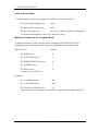
The manual is divided into the following parts:
Chapter 1
Hardware Overview describes the Satellite M500/M505/M507 system
unit and each FRU.
Chapter 2
Troubleshooting Procedures explains how to diagnose and resolve
FRU problems.
Chapter 3
Test and Diagnostics describes how to perform test and diagnostic
operations for maintenance service.
Chapter 4
Replacement Procedures describes the removal and replacement of the
FRUs.
Appendices
The appendices describe the following:
iv
Handling the LCD module
Board layout
Pin assignments
Keyboard scan/character codes
Key layout
BIOS rewrite procedures
EC/KBC rewrite procedures
[CONFIDENTIAL] Satellite M500/M505/M507 Maintenance Manual
Conventions
This manual uses the following formats to describe, identify, and highlight terms and
operating procedures.
Acronyms
On the first appearance and whenever necessary for clarification acronyms are enclosed in
parentheses following their definition. For example:
Read Only Memory (ROM)
Keys
Keys are used in the text to describe many operations. The key top symbol as it appears on
the keyboard is printed in boldface type.
Key operation
Some operations require you to simultaneously use two or more keys. We identify such
operations by the key top symbols separated by a plus (+) sign. For example, Ctrl + Pause
(Break) means you must hold down Ctrl and at the same time press Pause (Break). If
three keys are used, hold down the first two and at the same time press the third.
User input
Text that you are instructed to type in is shown in the boldface type below:
DISKCOPY A: B:
The display
Text generated by the computer that appears on its display is presented in the type face
below:
Format complete
System transferred
Satellite M500/M505/M507 Maintenance Manual [CONFIDENTIAL]
v
Table of Contents
Chapter 1
Hardware Overview
1.1
Features .................................................................... 1-Error! Bookmark not defined.
1.2
System Unit Block Diagram .................................... 1-Error! Bookmark not defined.
1.3
HDD/SSD ................................................................ 1-Error! Bookmark not defined.
1.4
DVD Super Multi Drive........................................... 1-Error! Bookmark not defined.
1.5
Keyboard.................................................................. 1-Error! Bookmark not defined.
1.6
TFT Color Display................................................... 1-Error! Bookmark not defined.
1.7
Power Supply ........................................................... 1-Error! Bookmark not defined.
1.8
Batteries ................................................................... 1-Error! Bookmark not defined.
1.9
AC Adaptor.............................................................. 1-Error! Bookmark not defined.
Chapter 2
Troubleshooting Procedures
Troubleshooting Procedures ........................................... 2-Error! Bookmark not defined. 2.1 Troubleshooting ....................................................... 2-Error! Bookmark not defined. 2.2 Troubleshooting Flowchart...................................... 2-Error! Bookmark not defined. 2.3 Power Supply Troubleshooting................................ 2-Error! Bookmark not defined. 2.4 Main Board Troubleshooting................................... 2-Error! Bookmark not defined. 2.5 HDD/SSD Troubleshooting ..................................... 2-Error! Bookmark not defined. 2.6 Keyboard and Touch pad Troubleshooting.............. 2-Error! Bookmark not defined. 2.7 Display Troubleshooting.......................................... 2-Error! Bookmark not defined. 2.8 Optical Drive Troubleshooting ................................ 2-Error! Bookmark not defined. 2.9 Modem Troubleshooting.......................................... 2-Error! Bookmark not defined. 2.10 LAN Troubleshooting.............................................. 2-Error! Bookmark not defined. 2.11 Wireless LAN Troubleshooting............................... 2-Error! Bookmark not defined. 2.12 Sound Troubleshooting............................................ 2-Error! Bookmark not defined. 2.13 Card Reader Slot Troubleshooting .......................... 2-Error! Bookmark not defined. 2.14 PCI Express Card Slot Troubleshooting .................. 2-Error! Bookmark not defined. 2.15 Fingerprint Board(BTO) Troubleshooting............... 2-Error! Bookmark not defined. vi
[CONFIDENTIAL] Satellite M500/M505/M507 Maintenance Manual
2.16 Bluetooth(BTO) Troubleshooting............................ 2-Error! Bookmark not defined. 2.17 3G(BTO) Troubleshooting....................................... 2-Error! Bookmark not defined. 2.18 Camera(BTO) Troubleshooting ............................... 2-Error! Bookmark not defined. Chapter 3
Tests and Diagnostics
Tests and Diagnostics .......................................................... 3-Error! Bookmark not defined.
3.1
Model,BIOS and CPU Test...................................... 3-Error! Bookmark not defined.
3.1.1
CPU Test.................................................................. 3-Error! Bookmark not defined.
3.1.2
Memory Test............................................................ 3-Error! Bookmark not defined.
3.2
Check MAC Test ..................................................... 3-Error! Bookmark not defined.
3.3
ACIN Test................................................................ 3-Error! Bookmark not defined.
3.4
Temperature Test ..................................................... 3-Error! Bookmark not defined.
3.5
USB TEST ............................................................... 3-Error! Bookmark not defined.
3.6
USBCCD Test.......................................................... 3-Error! Bookmark not defined.
3.7
PAD Test.................................................................. 3-Error! Bookmark not defined.
3.8
LCDRGB Test ......................................................... 3-Error! Bookmark not defined.
3.9
VGA Test ................................................................. 3-Error! Bookmark not defined.
3.10
Audio Test................................................................ 3-Error! Bookmark not defined.
3.11
Keyboard Test.......................................................... 3-Error! Bookmark not defined.
3.12
Function TEST......................................................... 3-Error! Bookmark not defined.
3.13
LEDALL Test .......................................................... 3-Error! Bookmark not defined.
3.14
STORE Test [CD/DVD-ROM TEST] ..................... 3-Error! Bookmark not defined.
3.15
LID Switch Test....................................................... 3-Error! Bookmark not defined.
3.16
MS CARD Test........................................................ 3-Error! Bookmark not defined.
3.17
SD CARD Test ........................................................ 3-Error! Bookmark not defined.
3.18
HDD Test ................................................................. 3-Error! Bookmark not defined.
3.19
BATTERY Test ....................................................... 3-Error! Bookmark not defined.
3.20
Touch LED Test....................................................... 3-Error! Bookmark not defined.
3.21
HDD 3D Protection.................................................. 3-Error! Bookmark not defined.
3.22
Speaker Test............................................................. 3-Error! Bookmark not defined.
3.23
Auto Run.................................................................. 3-Error! Bookmark not defined.
3.0
Appendix:................................................................. 3-Error! Bookmark not defined.
Satellite M500/M505/M507 Maintenance Manual [CONFIDENTIAL]
vii
Chapter 4
Replacement Procedures
4.1
General................................................................... Error! Bookmark not defined.
4.2
Battery pack ........................................................... Error! Bookmark not defined.
4.3
Express card ........................................................... Error! Bookmark not defined.
4.4
HDD module .......................................................... Error! Bookmark not defined.
4.5
Memory module..................................................... Error! Bookmark not defined.
4.6
Wireless LAN card ................................................ Error! Bookmark not defined.
4.7
Keyboard................................................................ Error! Bookmark not defined.
4.8
Top cover ............................................................... Error! Bookmark not defined.
4.9
Bluetooth................................................................ Error! Bookmark not defined.
4.10
Power Button Board............................................... Error! Bookmark not defined.
4.11
Fingerprint module................................................. Error! Bookmark not defined.
4.12
Touchpad on-off board .......................................... Error! Bookmark not defined.
4.13
Main PCB............................................................... Error! Bookmark not defined.
4.14
LAN Board............................................................. Error! Bookmark not defined.
4.15
D/C IN Cable ......................................................... Error! Bookmark not defined.
4.16
Speaker................................................................... Error! Bookmark not defined.
4.17
Remove LCD Module............................................ Error! Bookmark not defined.
4.18
CPU Heat sink/CPU............................................... Error! Bookmark not defined.
4.19
VGA Card .............................................................. Error! Bookmark not defined.
4.20
FAN Error! Bookmark not defined.
4.21
LCD unit/Camera................................................... Error! Bookmark not defined.
viii
[CONFIDENTIAL] Satellite M500/M505/M507 Maintenance Manual
Appendices
Appendix A
Handling the LCD Module ........................................................................... A-1
Appendix B
Board Layout ................................................................................................ B-1
Appendix C
Pin Assignments............................................................................................ C-1
Appendix D
Keyboard Scan/Character Codes .................................................................. D-1
Appendix E
Key Layout.....................................................................................................E-1
Appendix F
BIOS rewrite Procedures ............................................................................... F-1
Appendix G
EC/KBC rewrite Procedures ......................................................................... G-1
Satellite M500/M505/M507 Maintenance Manual [CONFIDENTIAL]
ix
1 Hardware Overview
Chapter 1
Hardware Overview
Satellite M500/M505/M507 Maintenance Manual [CONFIDENTIAL]
1-1
1 Hardware Overview
Chapter 1
Contents
1.1
Features ...................................................................................................................... 1-4
1.2
System Unit Block Diagram .................................................................................... 1-10
1.3
HDD/SSD ................................................................................................................ 1-15
1.3.1
2.5-inch Hard Disk Drive ................................................................... 1-15
1.3.2
SSD..................................................................................................... 1-16
1.4
DVD Super Multi Drive .......................................................................................... 1-17
1.5
Keyboard .................................................................................................................. 1-19
1.6
TFT Color Display ................................................................................................... 1-20
1.7
Power Supply ........................................................................................................... 1-21
1.8
Batteries ................................................................................................................... 1-22
1.9
1-2
1.8.1
Main Battery ....................................................................................... 1-22
1.8.2
Battery Charging Control ................................................................... 1-23
1.8.3
RTC battery ........................................................................................ 1-23
AC Adaptor .............................................................................................................. 1-25
[CONFIDENTIAL] Satellite M500/M505/M507 Maintenance Manual
1 Hardware Overview
Figures
Figure 1-1 The front and left view of the computer ............................................................ 1-8
Figure 1-2 System unit configuration .................................................................................. 1-9
Figure 1-3 System unit block diagram............................................................................... 1-10
Figure 1-4 2.5-inch HDD................................................................................................... 1-15
Figure 1-5 SSD .................................................................................................................. 1-16
Figure 1-6 DVD Super Multi Drive................................................................................... 1-17
Figure 1-7 Keyboard .......................................................................................................... 1-19
Tables
Table 1-1 2.5-inch HDD specifications (1/1) ..................................................................... 1-15
Table 1-2 1.8-inch SSD specifications (1/1)....................................................................... 1-16
Table 1-3 DVD Super Multi drive specifications (1/1) ..................................................... 1-18
Table 1-4 LCD module specifications (1/1) ...................................................................... 1-20
Table 1-5 Power supply output rating................................................................................ 1-21
Table 1-6 Battery specifications ........................................................................................ 1-22
Table 1-7 Time required for charges ................................................................................. 1-23
Table 1-8 RTC battery charging/data preservation time ................................................... 1-24
Table 1-9 AC adaptor specifications for integrated graphic model................................... 1-25
Table 1-10 AC adaptor specifications for discrete graphic model ...................................... 1-25
Satellite M500/M505/M507 Maintenance Manual [CONFIDENTIAL]
1-3
1 Hardware Overview
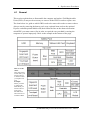
1.1 Features
The Toshiba Satellite M500/M505/M507 Personal Computer uses extensive Large Scale
Integration (LSI), and Complementary Metal-Oxide Semiconductor (CMOS) technology
extensively to provide compact size, minimum weight, low power usage and high reliability.
This computer incorporates the following features.
Comment [z1]:
Please add below item.
1.eSATA/USB combo port
2.webcam (BTO)
3.SIM card Slot
4.HDMI
5.Headphone/s/PDIF jack
6. Microphone jack
7.Bluetooth (BTO)
8. Fingerprint (BTO)
9. IEEE 1394 port
Refer to the Parts List for the configuration of each model and the available options.
Microprocessor
The Satellite M500/M505/M507 computer is equipped with an Intel® Core2 Duo
Processor, Intel® Pentium® Dual-Core mobile processor or Intel® Celeron Processor.
These processors incorporate a math co-processor with L2 cache memory.
Chipset
The Satellite M500/M505/M507 is equipped with Mobile Intel 4 Series Express Chipset
Family and Intel ICH9-M.
GPU (Graphics Processing Unit)
Comment [z2]:
Please add AMD M92XT
information.
(1) Integrated graphic model: Intel integrated graphics (Mobile Intel 4 Series Express
Chipset Family)
(2) Discrete graphic model: AMD M92XT
Comment [z3]:
Please add the below sentence
“It can incorporate up to 8GB of
main memory.”
Memory
The computer comes with two DDR2 SO-DIMM slots. Two memory modules of 1GB
(1,024MB), 2GB (2,048MB) or 4GB (4,096MB) can be installed, and it can incorporate
up to 8GB of main memory.
Comment [z4]:
Please add SSD information.
HDD/SSD
(1) HDD: The computer has a 2.5-inch SATA HDD. The following capacities are
available:
160/250/320/400/500 GB
(2) SSD (BTO): The computer has a SSD port with SATA interface supporting
TOSHIBA module type SSD.
Optical Drive
The computer accommodates a fixed 12.7mm ODD with one of following types:
1-4
[CONFIDENTIAL] Satellite M500/M505/M507 Maintenance Manual
Comment [z5]:
1. Please add more detail on ODD.
Ex : 12.7mm heigh DVD superMulti
driver support +- R double layer
2. Please add slot in ODD
information.
1 Hardware Overview
Tray Type DVD Super Multi +-R Double Layer drive
Tray Type DVD Super Multi +-R Double Layer with Label Flash™ drive
Slot Loading Type DVD Super Multi +-R Double Layer drive
Slot Loading Type DVD Super Multi +-R Double Layer with Label Flash™ drive
Display
The PC comes with 14.0W WXGA (1366*768) CSV LED backlight.
Keyboard
A4 size 86 key (US) and 87 key (UK) keyboard provides a numeric keypad overlay for
fast numeric data entry or for cursor and page control. The keyboard also includes two
keys that have special functions in Microsoft® Windows® Vista.
Pointing Device
The touch pad and control buttons enable control of the on-screen pointer and scrolling of
windows.
Batteries
The computer has two batteries: a rechargeable Lithium-Ion main battery pack and RTC
battery (that backs up the Real Time Clock and CMOS memory). The capacity of the
main battery pack can be either 6-cell or 12-cell depending on the model of computer.
Comment [z6]:
Modify sentence to
“The touch pad and control buttons
enable control of the on-screen
pointer and scrolling of windows.”
Comment [z7]:
Please add below sentence.
“The capacity can be either 6 cell or
12 cell depending on the model of
computer.”
Universal Serial Bus (USB2.0)
Three USB ports are provided. The ports comply with the USB2.0 standard, which
enables data transfer speeds 40 times faster than USB1.1 standard. USB1.1 is also
supported.
External monitor (RGB) port
The port enables connection of an external monitor, which is recognized automatically by
Video Electronics Standards Association (VESA) Display Data Channel (DDC)
compatible functions.
Comment [z8]:
Please add type of Express Card
( 134 and 154 module)
Express Card slot
An Express Card slot is provided, and accommodates an Express Card. Support the
standard 34mm wide module (ExpressCard / 34) and the standard 54mm wide module
(ExpressCard / 54).
Satellite M500/M505/M507 Maintenance Manual [CONFIDENTIAL]
1-5
1 Hardware Overview
Media Card slot
The Media Card Slot can accommodate all types of media (SD/Mini SD (card adapter is
needed)/Micro SD (card adapter is needed)/SDHC memory card/MMC/Memory
stick/Memory stick PRO/memory stick pro duo (card adapter is needed)/XD) with
various capacities. Media cards let you easily transfer data from devices, such as digital
cameras and Personal Digital Assistants, which use Media Card flash-memory.
Sound system
The sound system is equipped with the following features:
Azalia Link (Intel High Definition Audio I/F) built in the Intel ICH9-M + Realtek
ALC269
Amplifier: Realtek ALC269 built-in
Speaker: Non-brand or Harman/Kardon speaker (depending on model)
Internal modem
The computer contains an MDC, enabling data and fax communication. The transfer rates
are 56 Kbps for data reception. The actual speed depends on the line quality. The RJ11
modem jack is used to accommodate a telephone line.
Internal LAN (BTO)
The computer is equipped with LAN circuits that support Ethernet LAN (10/100 Mbps or
10/100/1000 Mbps). It also supports Wakeup on LAN (WOL), Magic Packet and LED.
Wireless LAN
The computer is equipped with PCI-E MiniCard type wireless LAN board that supports
802.11 a/b/g in the PCI-E MiniCard slot. This function can be switched on and off by a
switch on the computer.
eSATA / USB Combo port
The computer is equipped with an eSATA and USB combo port that supports connection
of an external eSATA or USB device.
The USB port complies with the USB 2.0 standard, which enables data transfer speeds 40
times faster than USB1.1 standard. USB1.1 is also supported, and also supports Sleep and
Charge function that can supply bus power to USB when the PC is sleeping.
1-6
[CONFIDENTIAL] Satellite M500/M505/M507 Maintenance Manual
Comment [z9]:
Please input all types (SD/Mini
SD/Micro SD/SDHC memory
card/MMC/Memory stick/Memory
stick PRO/memory stick pro duo/XD)
Comment [z10]:
Please add Harman/kardon
(Depending on model) information.
1 Hardware Overview
Webcam Module (BTO)
The computer is equipped with a webcam module which is embedded to transfer video
data – to take still image and offer video stream for end user to preview/record motion
image through USB 2.0 interface.
SIM card slot
A user accessible SIM card slot is provided behind battery.
HDMI port
A HDMI port is provided which complies with the HDMI 1.3 standard.
Headphone / S/PDIF jack
The computer is equipped with a headphone jack which is shared with S/PDIF jack.
Microphone Jack
The computer is equipped with a microphone jack.
Bluetooth Module (BTO)
The computer is equipped with a Bluetooth module with antenna through USB interface.
Fingerprint (BTO)
The fingerprint sensor can support on-chip fingerprint matching functionality and
security engine.
Satellite M500/M505/M507 Maintenance Manual [CONFIDENTIAL]
1-7
1 Hardware Overview
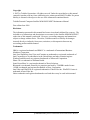
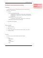
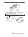
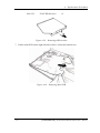
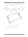
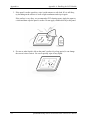
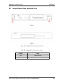
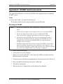
The front of the computer is shown in figure 1-1.
Figure 1-1 The front and left view of the computer
1-8
[CONFIDENTIAL] Satellite M500/M505/M507 Maintenance Manual
Comment [z11]:
Please use the more detail photo to
show computer and system unit
configuration.
1 Hardware Overview
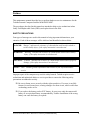
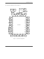
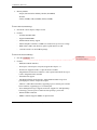
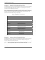
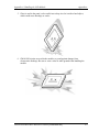
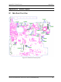
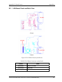
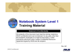
The system unit configuration is shown in figure 1-2.
M1TP_CON1
USB*2
LAN/RJ11
MLCON301
Touch PAD
Board
MLCON103
M1TP_J1
BTO
LAN
Board
MLCON101
CON6701
ODD
Function
Board
LCD
Touch
Panel
MDC
CON6501
BTO
Touch
PAD
Power
Button
Board
CON6503
T/P
ON/OFF
Board
Fingerprint
HP/
SPDIF
MIC
CON4804 CON4802 CON4202
CON4201
CON6002
CON7701
Battery
CON6601
J7701
DC-IN
CON3701
CON4801
Keyboard
CON6201
BTO
CON6204
BTO
Felica
CON6106
USB*1
RGB
CON3801
WWAN
CON5601
BTO
CON6001
HDD
eSATA/USB
CON6107
CON6003
BTO
SSD
Media
Card
CON5001
CON3901
BTO
HDMI
Upconvert
CON5501
BTO
CON6202
BTO
Camera
Main Board
CON5401
Newcard
CON6203
BlueToot
h
CON5701
CON2101
CON2201
CON410
1
CON5602
DIMM0
DIMM1
Speaker
SIM
card
CON4901
WLAN
FAN
Figure 1-2 System unit configuration
Satellite M500/M505/M507 Maintenance Manual [CONFIDENTIAL]
1-9
1 Hardware Overview
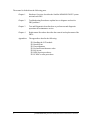
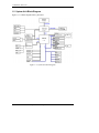
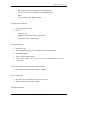
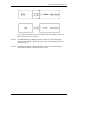
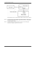
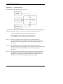
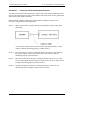
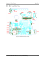
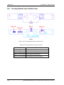
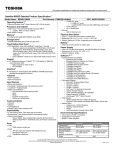
1.2 System Unit Block Diagram
Figure 1-3 is a block diagram of the system unit.
Figure 1-3 System unit block diagram
1-10
[CONFIDENTIAL] Satellite M500/M505/M507 Maintenance Manual
1 Hardware Overview
Comment [z12]:
Please add BIOS ROM (Flash EEP
ROM) information.
The system unit is composed of the following major components:
Comment [z13]:
Please add core speed detail.
Processor
Intel® Core2 Duo Processor, Intel® Pentium® Dual-Core mobile processor or
Mobile Intel® Celeron Processor
Core speed:
Intel® Core2 Duo mobile processors:
3.06GHz(T9900), 2.8GHz(P9700), 2.8GHz (T9600), 2.66GHz (P8800),
2.53GHz (P8700), 2.26GHz (P7550), 2.2GHz (T6600), 2.1GHz (T6500),
2.0GHz (P7350)
Intel® Pentium® Dual-Core mobile processor:
2.1GHz(T4300), 2.0GHz(T4200), 1.9GHz (T3100), 1.8GHz(T3000)
Mobile Intel® Celeron® Processors: 2.2GHz (900)
478-pin Micro FCPGA package
BIOS EEPROM
8 Mbit SPI serial flash
Supply voltage: 2.7~3.6V
Low power consumption: active read: 10mA (typical); standby: 5uA (typical).
8-lead SOIC package
Memory
Two memory slots are provided. Expansion up to 8GB is available.
Memory
– DDR2-SDRAM
– 800MHz
– 1.8 volt operation
– FBGA
Satellite M500/M505/M507 Maintenance Manual [CONFIDENTIAL]
1-11
1 Hardware Overview
Memory Module
– 200 pin, SO Dual In-line Memory Module (SO-DIMM)
– PC6400
– 1GB (1,024MB), 2GB (2,048MB), 4GB (4,096MB)
Intel GMCH (North Bridge)
One Intel® 4 Series Express Chipset is used
Features:
–
667/800/1066 MHz FSB
–
Supports DDR2/DDR3
–
8GB maximum memory support
–
Internal Graphics Controller: 533MHz core render clock @1.05V core voltage
–
DMI: 2GB/s (1GB/s each direction), point-to-point interface to ICH
–
1329-ball 34 mm x 34 mm FCBGA package
Intel ICH9-M (South Bridge)
1-12
One Intel ICH9-M is used
Features:
–
DMI (Direct Media Interface)
–
PCI Express: 6 PCI Express root ports, Supports PCI Express 1.1
–
PCI Bus I/F: Supports PCI Rev 2.3 Specification at 33 MHz
–
Integrated Serial ATA Host Controller: 6 SATA ports. Data transfer rates up to
3.0Gb/s. Integrated AHCI controller
–
External SATA support
–
Intel High Definition Audio Interface: Independent Bus Master logic for 8
general purpose streams: 4 input and 4 output
–
USB 2.0: 6 UHCI Host Controllers, supporting up to 12 external ports. 2 EHCI
Host Controllers, supporting up to 12 external ports
–
Power Management Logic: Supports ACPI 3.0b. Support for “Intel SpeedStep
Technology” processor power control and “Deeper Sleep” power state
–
Enhanced DMA Controller
–
SMBus controller: Supports SMBus 2.0 Specification
[CONFIDENTIAL] Satellite M500/M505/M507 Maintenance Manual
Comment [z14]:
This should be ICH9-M
1 Hardware Overview
–
Real-Time Clock: 256-byte battery-backed CMOS RAM
–
Low Pin Count (LPC) I/F: Supports 2 Master/DMA devices
–
GPIO
–
676-ball 31mm×31mm mBGA Package
Card Reader Controller
One Ricoh R5U230 is used
Futures:
–
PCI Express I/F
–
SD/MMC, Memory Stick, XD Card Controller
–
48-pin, 6mm×6mm, QFN Package
Sound Controller
Realtek ALC269
Mono Microphone-in and stereo headphone-out shared with SPDIF.
Internal Microphone
Volume control: Digital control
Stereo w/box, 4 ohm / 1.5W. L/R = 12.7cc/10.65cc (Harman/Kardon); 13cc/11cc
(Non-brand).
EC/KBC (Embedded Controller/Keyboard Controller)
One ITE8512E chip functions as both EC and KBC.
Clock Generator
One Intel CK-505 compatible clock generator is used.
This device generates the system clocks
Modem Controller
Satellite M500/M505/M507 Maintenance Manual [CONFIDENTIAL]
1-13
1 Hardware Overview
One MDC is used
This controller has the following functions:
–
One RJ11 port
–
Digital line protection support
–
V.92 (V.90) 56K Modem/FAX
LAN Controller
Realtek RTL8103EL or RTL8111DL is used (depending on model)
This controller has the following functions:
–
PCIE I/F
–
Supports 10/100 Mbps or 10/100/1000 Mbps Ethernet
–
–
One RJ45 port
WOL support
–
Magic Packet support
Wireless LAN
One PCI-E MiniCard is used
Support 802.11 a/b/g/n or 802.11 a/b/g or 802.11 b/g/n
Sensor
1-14
Thermal Sensor: One MAXIM MAX6657 or compatible chip is used
[CONFIDENTIAL] Satellite M500/M505/M507 Maintenance Manual
1 Hardware Overview
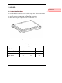
1.3 HDD/SSD
Comment [z15]:
Please add SSD information.
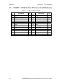
1.3.1 2.5-inch Hard Disk Drive
The removable HDD is a random access non-volatile storage device. It has a non-removable
2.5-inch magnetic disk and mini-Winchester type magnetic heads.
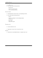
The computer supports a 160GB, 250GB, 320GB, 400GB and 500GB.
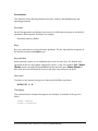
The HDD is shown in figure 1-4. Specifications are listed in Table 1-1.
Figure 1-4 2.5-inch HDD
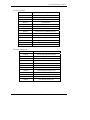
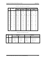
Table 1-1 2.5-inch HDD specifications (1/1)
Item
Capacity (GB)
Rotational Speed (RPM)
Height
User Data Sectors
Bytes / Sector
Specifications
160 GB
250 GB
320 GB
5400 rpm
5400 rpm
5400 rpm
9.5 mm
9.5 mm
9.5 mm
312,581,808
488,397,168
625,142,448
512
512
512
Satellite M500/M505/M507 Maintenance Manual [CONFIDENTIAL]
1-15
1 Hardware Overview
Item
Specifications
Capacity (GB)
Rotational Speed (RPM)
Height
User Data Sectors
Bytes / Sector
1.3.2
400 GB
500 GB
5400 rpm
5400 rpm
9.5 mm
9.5 mm
781,422,768
976,773,168
512
512
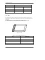
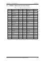
SSD
The solid-state drive (SSD) is a data storage device that uses solid-state memory to store
persistent data. A SSD emulates a hard disk drive interface, thus easily replacing it in most
applications.
The computer supports a dedicated SSD port with TOSHIBA module type SSD.
The SSD is shown in figure 1-5. Specifications are listed in Table 1-2.
Figure 1-5 SSD
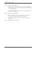
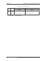
Table 1-2 1.8-inch SSD specifications (1/1).
Item
Specifications
64 GB
Capacity (GB)
16
Number of data heads
Number of user data cylinders
User Addressable Sectors in LBA Mode
Bytes / Sector
1-16
16,383
125,045,424
512
[CONFIDENTIAL] Satellite M500/M505/M507 Maintenance Manual
1 Hardware Overview
Comment [z16]:
Please add DVD drive photo.
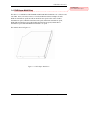
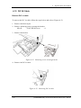
1.4 DVD Super Multi Drive
This drive is a combination of DVD-ROM and DVD±R/±RW/-RAM Drive. It is full-size and
runs either 12cm (4.72-inch) or 8cm (3.15-inch) DVD/CDs without an adaptor. It reads
DVDs at maximum 8x speed and CDs at maximum 24x speed. It also writes CD-R at
maximum 24x speed, CD-RW at maximum 24x speed, DVD±R at maximum 8x speed,
DVD-RW at maximum 6x speed, DVD+RW at maximum 8x speed, DVD±R DL at
maximum 6x speed and DVD-RAM at maximum 3-5x speed.
The DVD is shown in figure 1-6.
Figure 1-6 DVD Super Multi drive
Satellite M500/M505/M507 Maintenance Manual [CONFIDENTIAL]
1-17
1 Hardware Overview
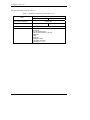
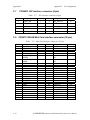
The specifications are listed in Table 1-3.
Table 1-3 DVD Super Multi drive specifications (1/1)
Specifications
Item
DVD-ROM mode
SATA Interface (Mbytes/s)
Average access time (ms)
Data Buffer Capacity
Support Formats
1-18
CD-ROM mode
150 Mbyte/s
180ms Typ.
150ms Typ.
2MB
CD-DA, CD-ROM
CD-ROM XA
Photo CD (Multi-session)
Video CD, CD-Extra(CD+), CD-Text
DVD-ROM
DVD-R
DVD-Video
DVD-RAM (4.7GB)
DVD+R/RW, DVD+R DL
DVD-RW(Ver. 1.1/1.2)
[CONFIDENTIAL] Satellite M500/M505/M507 Maintenance Manual
1 Hardware Overview
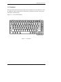
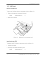
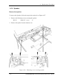
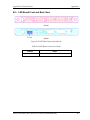
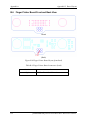
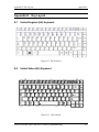
1.5 Keyboard
The keyboard has 86(US)/87(UK) keys that consist of character keys and control keys, and is
in conformity with JIS. The keyboard is connected to a membrane connector on the system
board and is controlled by EC.
Figure 1-7 is a view of the keyboard.
Figure 1-7 Keyboard
Satellite M500/M505/M507 Maintenance Manual [CONFIDENTIAL]
1-19
1 Hardware Overview
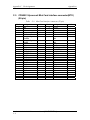
1.6 TFT Color Display
The TFT color display consists of 14.0-inch LCD module.
The LCD module used for the TFT color display uses a LED backlight as the light source
and can display a maximum of 262,144 colors with 1366*768 resolution.
Table 1-4 lists the specifications.
Table 1-4 LCD module specifications (1/1)
Specifications
Item
14.0" WXGA (1366*768)
CSV type
Number of Dots
1-20
1,366 (W) * 768 (H)
Dot spacing (mm)
0.2265(H) * 0.2265(V)
Display range (mm)
309.4(H) * 173.95(V)
[CONFIDENTIAL] Satellite M500/M505/M507 Maintenance Manual
1 Hardware Overview
1.7 Power Supply
The power supply provides different voltages to the system board and performs the following
functions:
1. Determines that the DC power supply (AC adapter) is connected to the computer.
2. Detects DC output and circuit malfunctions.
3. Controls the battery icon, and DC IN icon.
4. Turns the battery charging system on and off and detects a fully charged battery.
5. Turns the power supply on and off.
6. Provides more accurate detection of a low battery.
7. Calculates the remaining battery capacity.
8. Controls the transmission of the status signal of the main battery.
The power supply output rating is specified in Table 1-5.
Table 1-5 Power supply output rating
Name
Voltage (V)
Use
+VCORE
VID (Intel spec)
+VCCP
1.05
CPU, GMCH, ICH9-M
+1.5VS
1.5
CPU, GMCH, ICH9-M, Express Card, Mini Card
+1.8V
1.8
GMCH, DDR2-SDRAM
+0.9V
0.9
DDR2-SDRAM
+3VSUS
3.3
ICH9-M, Express Card, Mini Card, LAN, HDMI CEC
+3V
3.3
MDC
+3VS
3.3
Thermal Sensor, Clock gen, LCD, DDR2-SDRAM, ICH9M, Express Card, Mini Card, EC, GMCH, Fingerprint, Card
Reader, SSD, Bluetooth
+3VA
3.3V
+5VA
5
Function Board
+5VSUS
5
ICH9-M, USB
+5VS
5
FAN, ICH9-M, Audio, ODD, HDD, LED, Touchpad,
Keyboard backlight, CCD, FeliCa, G-sensor
CPU
EC, SPI ROM
Satellite M500/M505/M507 Maintenance Manual [CONFIDENTIAL]
1-21
1 Hardware Overview
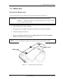
1.8 Batteries
The computer has two types of batteries as follows:
Main battery pack
RTC battery
The battery specifications are listed in Table 1-6.
Table 1-6 Battery specifications
Battery name
Material
Output voltage
Capacity
Main battery(6 cell)
Lithium-Ion
10.8V
4000 mAh
Main battery(12cell)
Lithium-Ion
10.8V
9000 mAh
Lithium
3.0 V
18 mAh
RTC battery
1.8.1 Main Battery
The removable main battery pack is the computer’s main power source when the AC adaptor
is not attached. The main battery maintains the state of the computer when the computer
enters into resume mode.
1-22
[CONFIDENTIAL] Satellite M500/M505/M507 Maintenance Manual
1 Hardware Overview
1.8.2 Battery Charging Control
Battery charging is controlled by an embedded controller (EC). The EC controls whether the
charge is on or off and detects a full charge when the AC adaptor and battery are attached to
the computer. The system charges the battery.
Battery Charge
When the AC adaptor is attached, there are two types of charge: When the system is powered
off and when the system is powered on. Table 1-7 lists the charging time required for charges.
Table 1-7 Time required for charges
Battery type
Power on (hours)
Power off (hours)
4-10 hours
4 hours max
About 24 hours
About 24 hours
1st battery pack (6cell,12cell)
RTC Battery
NOTE: The time required when the system is powered on is affected by the amount of
power the system is consuming. Use of the fluorescent lamp and frequent disk
access diverts power and lengthens the charge time.
If any of the following occurs, the battery charge process stops.
1. The battery becomes fully charged.
2. The AC adaptor or battery is removed.
3. The battery or output voltage is abnormal.
Detection of full charge
A full charge is detected only when the battery is charging at charge. A full charge is
detected under any of the following conditions:
1. The current in the battery charging circuit drops under the predetermined limit.
2. The charging time exceeds the fixed limit.
1.8.3 RTC battery
The RTC battery provides power to keep the current date, time and other setup information
in memory while the computer is turned off. Table 1-8 lists the data preservation period of
the RTC battery.
Satellite M500/M505/M507 Maintenance Manual [CONFIDENTIAL]
1-23
1 Hardware Overview
Table 1-8 RTC battery charging/data preservation time
Status
Data preservation period (full charge)
1-24
Time
90 days
[CONFIDENTIAL] Satellite M500/M505/M507 Maintenance Manual
1 Hardware Overview
1.9 AC Adaptor
The AC adaptor is also used to charge the battery.
Table 1-9 lists the AC adaptor specifications.
Table 1-9 AC adaptor specifications for integrated graphic model
Parameter
Specification
2-pin
Power
3-pin
65W
Input voltage
100V-240V
Input frequency
50Hz–60Hz
Input current
1.6A or less (100V-240V)
Output voltage
19V
Output current
0A to 3.42A (At constant voltage mode)
Table 1-10 AC adaptor specifications for discrete graphic model
Parameter
Specification
2-pin
Power
3-pin
75W
Input voltage
100V-240V
Input frequency
50Hz - 60Hz
Input current
1.5A or less (100V-240V)
Output voltage
19V
Output current
0A to 3.95A (At constant voltage mode)
Satellite M500/M505/M507 Maintenance Manual [CONFIDENTIAL]
1-25
2 Troubleshooting Procedures
Chapter 2
Troubleshooting Procedures
Satellite M500/M505/M507 Maintenance Manual [CONFIDENTIAL]
2-1
2 Troubleshooting Procedures
Chapter 2
Contents
Troubleshooting Procedures......................................................................................... 2-1 2.1 Troubleshooting ......................................................................................................... 2-5 2.2 Troubleshooting Flowchart ........................................................................................ 2-6 2.3 Power Supply Troubleshooting................................................................................ 2-10 Procedure 1 Icons in the LCD Check .............................................................. 2-10 Procedure 2 Error Code Check ........................................................................ 2-11 Procedure 3 Connection Check ....................................................................... 2-15 Procedure 4 Charge Check .............................................................................. 2-16 Procedure 5 Replacement Check ..................................................................... 2-17 2.4 Main Board Troubleshooting ................................................................................... 2-18 Procedure 1 Message Check............................................................................ 2-19 Procedure 2 Diagnostic Test Program Execution Check ................................ 2-21 Procedure 3 Replacement Check ..................................................................... 2-22 2.5 HDD/SSD Troubleshooting ..................................................................................... 2-23 Procedure 1 Message Check............................................................................ 2-23 Procedure 2 Partition Check ............................................................................ 2-24 Procedure 3 Format Check .............................................................................. 2-25 Procedure 4 Diagnostic Test Program Execution Check ................................ 2-26 Procedure 5 Connector Check and Replacement Check ................................. 2-26 2.6 Keyboard and Touch pad Troubleshooting.............................................................. 2-28 Procedure 1 Diagnostic Test Program Execution Check ................................ 2-28 Procedure 2 Connector Check and Replacement Check ................................. 2-29 2.7 Display Troubleshooting .......................................................................................... 2-31 Procedure 1 External Monitor Check .............................................................. 2-31 Procedure 2 Diagnostic Test Program Execution Check ................................ 2-31 Procedure 3 Connector Check and Cable Check............................................. 2-31 Procedure 4 Replacement Check ..................................................................... 2-32 2.8 Optical Drive Troubleshooting ................................................................................ 2-33 Procedure 1 Diagnostic Test Program Execution Check ................................ 2-33 Procedure 2 Connector Check and Replacement Check ................................. 2-34 2-2
[CONFIDENTIAL] Satellite M500/M505/M507 Maintenance Manual
2 Troubleshooting Procedures
2.9 Modem Troubleshooting .......................................................................................... 2-35 Procedure 1 Diagnostic Test Program Execution Check ................................ 2-35 Procedure 2 Connector Check and Replacement Check ................................. 2-36 2.10 LAN Troubleshooting .............................................................................................. 2-37 Procedure 1 Diagnostic Test Program Execution Check ................................ 2-37 2.11 Wireless LAN Troubleshooting ............................................................................... 2-38 Procedure 1 Transmitting-Receiving Check ................................................... 2-38 Procedure 2 Antenna Connection Check......................................................... 2-39 Procedure 3 Replacement Check ..................................................................... 2-40 2.12 Sound Troubleshooting ............................................................................................ 2-41 Procedure 1 Diagnostic Test Program Execution Check ................................ 2-41 Procedure 2 Connector Check ......................................................................... 2-42 Procedure 3 Replacement Check >>>> ........................................................... 2-43 2.13 Card Reader Slot Troubleshooting........................................................................... 2-44 Procedure 1 Check on Windows VISTA(TM) ................................................ 2-44 Procedure 2 Connector Check and Replacement Check ................................. 2-44 2.14 PCI Express Card Slot Troubleshooting .................................................................. 2-45 Procedure 1 Check on Windows VISTA(TM) ................................................ 2-45 Procedure 2 Connector Check and Replacement Check ................................. 2-45 2.15 Fingerprint Board(BTO) Troubleshooting ............................................................... 2-47 Procedure 1 Diagnostic Test Program Execution Check ................................ 2-47 Procedure 2 Connector Check and Replacement Check ................................. 2-48 2.16 Bluetooth(BTO) Troubleshooting ............................................................................ 2-49 Procedure 1 Diagnostic Test Program Execution Check ................................ 2-49 Procedure 2 Connector Check and Replacement Check ................................. 2-50 2.17 3G(BTO) Troubleshooting....................................................................................... 2-51 Procedure 1 Diagnostic Test Program Execution Check ................................ 2-51 Procedure 2 Connector Check and Replacement Check ................................. 2-52 2.18 Camera(BTO) Troubleshooting ............................................................................... 2-53 Procedure 1 Diagnostic Test Program Execution Check ................................ 2-53 Procedure 2 Connector Check and Replacement Check ................................. 2-54 Satellite M500/M505/M507 Maintenance Manual [CONFIDENTIAL]
2-3
Comment [z1]:
1.Please add SSD troubleshooting,
camera (BTO) troubleshooting and
thermal module troubleshooting.
2.add “ BTO” behind 2.15 fingerprint
board troubleshooting , Bluetooth
troubleshooting and 3G troubleshooting.
2 Troubleshooting Procedures
Figures
Figure 2-1 Troubleshooting flowchart (1/2) ......................................................................... 2-7
Tables
Table 2-1 Battery icon ........................................................................................................ 2-10
Table 2-2 DC IN icon ......................................................................................................... 2-10
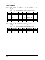
Table 2-3 Error code ........................................................................................................... 2-11
Table 2-4 HDD/SSD error code and status......................................................................... 2-26
2-4
[CONFIDENTIAL] Satellite M500/M505/M507 Maintenance Manual
2 Troubleshooting Procedures
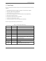
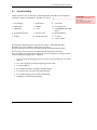
2.1
Troubleshooting
Chapter 2 describes how to determine if a Field Replaceable Unit (FRU) in the computer is
causing the computer to malfunction. The FRUs covered are:
1 Power Supply
6 Optical Drive
11 Card reader
2 Main Board
7 Modem
12 PCI Express Slot
3 HDD/SSD
8
13 FINGERPRINT BOARD
(BTO)
4 Keyboard/Touch pad
9 Wireless LAN
5 Display
LAN
10 Sound component
14 Bluetooth (BTO)
15 3G (BTO)
16
Camera (BTO)
The Diagnostics Disk operations are described in Chapter 3. Detailed Replacement
Procedures are given in Chapter 4, Replacement Procedures.
The following tools are necessary for implementing the troubleshooting procedures:
The following tools are necessary for implementing the Diagnostics procedures:
For tools required for executing the Test Program, refer to the Chapter 3. For tools required
for disassembling/assembling, refer to Chapter 4.
1. A set of tools for the debugging port test (test cable, test board, RS-232C cross cable,
display,)
2. A PC with a serial port (for displaying debug port test result)
3. A bootable USB key
4. An external CRT display (for Display troubleshooting)
5. A Card reader (for Card reader slot troubleshooting)
6. An external microphone (for Sound troubleshooting)
7. Headphone (for Sound troubleshooting)
Satellite M500/M505/M507 Maintenance Manual [CONFIDENTIAL]
2-5
Comment [z2]:
1.Please add SSD ,camera (BTO) and
thermal module
2.Add “BTO” behind #13 Fingerprint
board, #14 Bluetooth and #15 3G
2 Troubleshooting Procedures
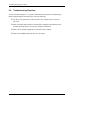
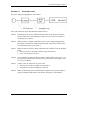
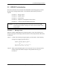
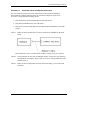
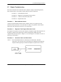
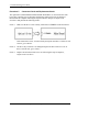
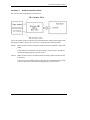
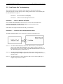
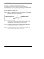
2.2
Troubleshooting Flowchart
Use the flowchart in Figure 2-1 as a guide for determining which FRU is malfunctioning.
Before going through the flowchart steps, check the following:
Ask the user if a password is registered and, if it is, ask him or her to enter the
password.
Make sure that Toshiba Windows VISTA(TM) is installed on the hard disk. NonToshiba operating systems can cause the computer malfunction.
Make sure all optional equipment is removed from the computer.
Make sure the HDD and optical drive bays are empty.
2-6
[CONFIDENTIAL] Satellite M500/M505/M507 Maintenance Manual
2 Troubleshooting Procedures
Figure 2-1 Troubleshooting flowchart (1/2)
Satellite M500/M505/M507 Maintenance Manual [CONFIDENTIAL]
2-7
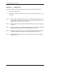
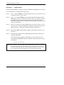
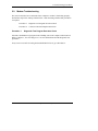
2 Troubleshooting Procedures
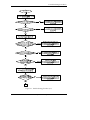
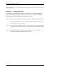
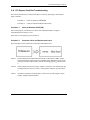
1
Do typed characters appear correctly?
No
Perform the Keyboard/Touch
pad Troubleshooting
Procedures in section 2.6
Yes
Use the diagnostic HDD and run
the diagnostics test program.(PC
reboot is required)
Refer to section 3.2 to start
the diagnostic test program
Is the diagnostic test loaded?
Yes
Perform each diagnostic test
Is an error detected by any of the
diagnostic tests?
Yes
After conforming which diagnostic test
has detected an error, perform the
appropriate procedures as outlined
below.
No
System is normal.
END
Figure 2-1 Troubleshooting flowchart (2/2)
2-8
[CONFIDENTIAL] Satellite M500/M505/M507 Maintenance Manual
2 Troubleshooting Procedures
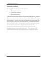
If the diagnostics program cannot detect an error, the problem may be intermittent. The
Running Test program should be executed several times to isolate the problem. Check the
Log Utilities function to confirm which diagnostic test detected an error, then perform the
appropriate troubleshooting procedures as follows:
1. If an error is detected on the system test, memory test, real timer test, perform the
Main Board Troubleshooting Procedures in Section 2.4.
2. If an error is detected on the hard disk test, perform the HDD Troubleshooting
Procedures in Section 2.5.
3. If an error is detected on the keyboard test, perform the Keyboard and Touch pad
Troubleshooting Procedures in Section 2.6.
4. If an error is detected on the display test, perform the Display Troubleshooting
Procedures in Section 2.7.
5. If an error is detected on the CD-ROM/DVD-ROM test, perform the Optical Drive
Troubleshooting Procedures in Section 2.8.
6. If an error is detected on the modem test, perform the Modem Troubleshooting
Procedures in Section 2.9.
7. If an error is detected on the LAN test, perform the LAN Troubleshooting Procedures
in Section 2.10.
8. If an error is detected on the Wireless LAN test, perform the Wireless LAN
Troubleshooting Procedures in Section 2.11.
9. If an error is detected on the sound test, perform the Sound Troubleshooting
Procedures in Section 2.12.
10. If an error is detected on card reader, perform the card reader Slot Troubleshooting
Procedures in Section 2.13.
11. If an error is detected on PCI Express, perform the PCI Express Slot Troubleshooting
Procedures in Section 2.14.
12. If an error is detected on Fingerprint board, perform the Fingerprint board
Troubleshooting Procedures in Section 2.15.
13. If an error is detected on Bluetooth, perform the Bluetooth Troubleshooting
Procedures in Section 2.16.
14. If an error is detected on 3G, perform the 3G Troubleshooting Procedures in Section
2.17.
Satellite M500/M505/M507 Maintenance Manual [CONFIDENTIAL]
2-9
2 Troubleshooting Procedures
15. If an error is detected on camera, perform the camera Troubleshooting Procedures in
Section 2.18.
2-10
[CONFIDENTIAL] Satellite M500/M505/M507 Maintenance Manual
2 Troubleshooting Procedures
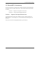
2.3
Power Supply Troubleshooting
The power supply controls many functions and components. To determine if the power
supply is functioning properly, start with Procedure 1 and continue with the other Procedures
as instructed. The procedures described in this section are:
Procedure 1: Icons in the LCD Check
Procedure 2: Error Code Check
Procedure 3: Connection Check
Procedure 4: Charge Check
Procedure 5: Replacement Check
Procedure 1
Icons in the LCD Check
The following Icons in the LCD indicate the power supply status:
Battery icon
DC IN icon
The power supply controller displays the power supply status through the Battery icon and
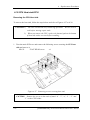
the DC IN icon in the LCD as listed in the tables below. To check the power supply status,
install a battery pack and connect an AC adaptor.
Table 2-1 Battery icon
Battery icon
Power supply status
Lights orange
Battery has been charging and AC adaptor is connected.
Lights white
Battery is fully charged and AC adaptor is connected.
Flashes orange
Battery charge is low. The AC adaptor must be connected to recharge
the battery.
Doesn’t light
Any condition other than those above.
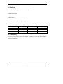
Table 2-2 DC IN icon
DC IN icon
2-10
Power supply status
Lights white
DC power is being supplied from the AC adaptor.
Doesn’t light
Any condition other than those above.
[CONFIDENTIAL] Satellite M500/M505/M507 Maintenance Manual
2 Troubleshooting Procedures
Comment [z3]: Please provide more
detail how to get Error code.
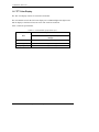
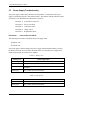
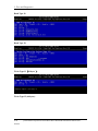
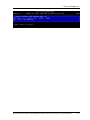
Procedure 2
Error Code Check
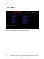
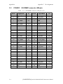
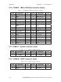
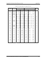
If the power supply microprocessor detects a malfunction, it indicates the error code as
shown below.
The error code begins with the least significant digit.
Table 2-3 Error code
Error code
Where Error occurs
N0FB*
Battery
N0FT*
Power ON/OFF
N0FU*
Power management
Satellite M500/M505/M507 Maintenance Manual [CONFIDENTIAL]
2-11
2 Troubleshooting Procedures
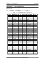
Check 1
Compare the patterns in the hexadecimal error code to the tables below.
Battery
2-12
Error code
Meaning
N0FB01
FCC、LMD under Spec.
N0FB02
Initial Data of FCC、LMD is without updating
N0FB03
Battery Learning abnormal function
N0FB04
Battery Check Error
N0FB05
No battery Icon in Windows
N0FB06
Battery data is locked
N0FB07
Abnormal Display on Battery LED
N0FB08
Battery PIC VERSION ERROR
N0FB09
RTC battery current in abnormal condition
N0FB0A
Battery On/Off function Error
N0FB0B
Unseal error
N0FB0C
Communication Fail
N0FB0D
To charge&To Discharge electricity fail
N0FB0E
Vcc is Fail
N0FB0F
Temperature fail
N0FB0G
EEeprom address check error(Bq2060)
N0FB0H
Ovp fail
N0FB0J
Uvp fail
N0FB0K
Cfc fail
N0FB0L
No battery Icon in SideShow
N0FB0M
assistant Battery Check Error
[CONFIDENTIAL] Satellite M500/M505/M507 Maintenance Manual
2 Troubleshooting Procedures
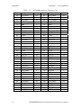
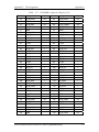
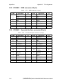
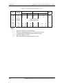
Power ON/OFF
Error code
Meaning
N0FT01
Cannot Boot Up
N0FT02
System Hang UP when Boot UP
N0FT03
Repeat Boot UP
N0FT04
Auto Shutdown
N0FT05
System Hang Up when Run-In Test
N0FT06
Cannot Power Off by ON/OFF Switch
N0FT07
Can't Soft Power ON and Power OFF
N0FT08
Power On Error by Battery Input only
N0FT09
Reset Key Test Error
N0FT0A
Can't auto boot up when insert Adaptor
N0FT0B
Can't boot up by fast key.
N0FT0C
Can't auto slot on boot up with Slot in ODD.
N0FT0D
Cannot Boot Up by novo key
N0FT0E
system hang on when Power Off
Power management
Error code
Meaning
N0FU01
Cannot restore after Dos Suspend
N0FU02
System Hang Up after DOS Wake Up
N0FU03
Cannot Run Dos Suspend
N0FU04
Cannot restore after Windows Standby
N0FU05
System Hang Up after Windows Wake Up
N0FU06
Cannot Run Windows Standby
N0FU07
Suspend to disk failed
N0FU08
Power Management System Fail
N0FU09
MAX error fail
N0FU0A
Cannot restore after Linux Standby
N0FU0B
System Hang Up after Linux Wake Up
N0FU0C
Linux Standby function error
Satellite M500/M505/M507 Maintenance Manual [CONFIDENTIAL]
2-13
2 Troubleshooting Procedures
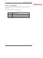
Check 2
In the case of error code N0FT0A:
Make sure the AC adaptor cord and AC power cord are firmly plugged into
the DC IN 19 V socket and wall outlet. If the cables are connected correctly,
go to the following step:
Connect a new AC adaptor and/or AC power cord, if necessary. If the error
still exists, go to Procedure 5.
Check 3
In the case of error code N0FB04:
Make sure the battery pack is correctly installed in the computer. If the
battery pack is correctly installed, go to the following step:
Replace the battery pack with a new one. If the error still exists, go to
Procedure 5.
Check 4
2-14
For any other error, go to Procedure 5.
[CONFIDENTIAL] Satellite M500/M505/M507 Maintenance Manual
2 Troubleshooting Procedures
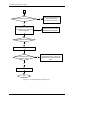
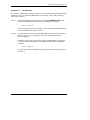
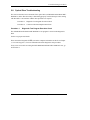
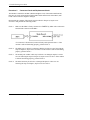
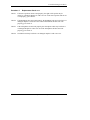
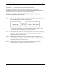
Procedure 3
Connection Check
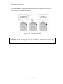
The power supply wiring diagram is shown below:
Any of the connectors may be disconnected. Perform Check 1.
Check 1
Disconnect the AC power cord from the wall outlet. Check the power cable for
breaks. If the power cord is damaged, connect a new AC power cord. If there is
no damage, go to Check 2.
Check 2
Make sure the AC adaptor cord and AC power cord are firmly plugged into the
DC-IN jack socket and AC adaptor inlet/wall outlet, respectively. If these cables
are connected correctly, go to Check 3.
Check 3
Make sure the DC IN jack is firmly connected to the connector J7701 on the main
board.
If the DC IN jack is not firmly connected, go to Procedure 5.
If it is connected, go to Check 4.
Check 4
Use a multimeter to make sure the AC adaptor output voltage is close to 19 V. If
the output is several percent lower than 19 V, go to Check 5. If the output is close
to 19 V, go to Check 6.
Check 5
Connect a new AC adaptor or AC power cord.
If the DC IN icon does not light, go to Procedure 5.
If the battery icon does not light, go to Check 6.
Check 6
Make sure the battery pack is installed in the computer correctly. If the battery is
properly installed and the battery icon still does not light, go to Procedure 4.
Satellite M500/M505/M507 Maintenance Manual [CONFIDENTIAL]
2-15
2 Troubleshooting Procedures
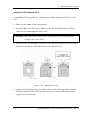
Procedure 4
Charge Check
The power supply may not charge the battery pack. Perform the following procedures:
1. Reinstall the battery pack.
2. Attach the AC adaptor and turn on the power. If you cannot turn on the power, go to
Procedure 5.
Check 1
Make sure the AC adaptor and AC power cord is firmly plugged into the DC IN
socket and the wall outlet. If these cables are connected correctly, replace the AC
adaptor (and/or AC power cord, if necessary).
Check 2
Make sure the battery is properly installed. If the battery is properly installed, go
to Check 3.
Check 3
The battery pack may be completely discharged. Wait a few minutes to charge the
battery pack. If the battery pack is still not charged, go to Check 4.
Check 4
The battery’s temperature is too hot or cold. Return the temperature to a normal
operating condition. If the battery pack still is not charged, go to Check 5.
Check 5
Replace the battery pack with a new one. If the battery pack still is not charged,
go to Procedure 5.
2-16
[CONFIDENTIAL] Satellite M500/M505/M507 Maintenance Manual
2 Troubleshooting Procedures
Procedure 5
Replacement Check
The main board processor module may be disconnected or damaged. Disassemble the
computer following the steps described in Chapter 4, Replacement Procedures. Check the
connection between the AC adaptor and main board and connection. After checking the
connections, perform the following Check 1:
Check 1
Replace the AC adaptor with a new one. If the AC adaptor is still not functioning
properly, perform Check 2.
Check 2
Replace the main board with a new one following the steps described in Chapter
4, Replacement Procedures.
Satellite M500/M505/M507 Maintenance Manual [CONFIDENTIAL]
2-17
2 Troubleshooting Procedures
2.4
Main Board Troubleshooting
This section describes how to determine if the main board and CPU are defective or not
functioning properly. Start with Procedure 1 and continue with the other procedures as
instructed.
The procedures described in this section are:
Procedure 1: Message Check
Procedure 2: Diagnostic Test Program Execution Check
Procedure 3: Replacement Check
2-18
[CONFIDENTIAL] Satellite M500/M505/M507 Maintenance Manual
2 Troubleshooting Procedures
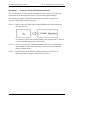
Procedure 1
Message Check
When the power is turned on, the system performs the Power On Self Test (POST) installed
in the BIOS ROM. The POST tests each IC on the main board and initializes it.
If an error message is shown on the display, perform Check 1.
If Toshiba MS-DOS or Windows VISTA(TM) is properly loaded, go to Procedure 2.
Check 1
If one of the following error messages appears on the screen, press F1 as the
message instructs. These errors occur when the system configuration preserved in
the RTC memory (CMOS type memory) is not the same as the actual
configuration or when the data is lost.
Press F1 as the message instructs to return all system settings to their default
values. Then the system reboots. Press F2 to run setup.
If an error message (a) appears often when the power is turned on, replace the
RTC battery. If any other error message displays, perform Check 2.
(a)
CMOS Battery Low
Press F2 to Run Setup, Press F1 to Load Default
Values and Continue.
(b)
RAM READ/WRITE Test Failed
Press F2 to Run Setup, Press F1 to Load Default
Values and Continue.
(c)
CMOS DATE/TIME Not Set
Press F2 to Run Setup, Press F1 to Load Default
Values and Continue.
(d)
CMOS Settings Wrong
Press F2 to Run Setup, Press F1 to Load Default
Values and Continue.
(e)
Primary Master Hard Disk Error
Press F2 to Run Setup, Press F1 to Load Default
Values and Continue.
Satellite M500/M505/M507 Maintenance Manual [CONFIDENTIAL]
2-19
2 Troubleshooting Procedures
Check 2
The POST checks the main board. When the POST detects an error, the system
stops or an error message appears.
If one of the following error messages (1) through (3), (5) or (11) appears, go to
Procedure 3.
If the error message (12), (13) appears, go to the Keyboard Troubleshooting
Procedures in Section 2.7.
If the error message (15) appears, go to the HDD Troubleshooting Procedures in
Section 2.6.
(1).
(2).
(3).
(4).
(5).
(6).
(7).
(8).
(9).
(10).
(11).
(12).
(13).
(14).
(15).
2-20
Refresh timer test failed
KBC BAT Test failed
RAM R/W test failed
KBC BAT Test failed
CMOS Battery Low
CMOS Settings Wrong
CMOS Date/Time Not Set
DMA Controller Error
DMA-1 Error
DMA-2 Error
Timer Error
Keyboard/Interface Error
PS2 Keyboard not found
PS2 Mouse not found
Primary Master Hard Disk Error
[CONFIDENTIAL] Satellite M500/M505/M507 Maintenance Manual
2 Troubleshooting Procedures
Procedure 2
Diagnostic Test Program Execution Check
Execute the following tests from the Diagnostic Test Menu. Refer to Chapter 3, Tests and
Diagnostics, for more information on how to perform these tests.
1. Check MAIN Ver
D. KB Test
2. Model, BIOS and CPU Test
E. MEMSIZE Test
3. Check MAC Test
F. FNTEST Test
4. ACIN Test
G. LEDALL Test
5. Temperature Test
H. STORE Test
6. USB Test
I. LED/LCDEDID Test
7. USBCCD Test
J. MSCARD Test
8. PAD Test
K. SDCARD Test
9. LCDRGB Test
L. HDD Test
A. BLUETOOTH Test
M. BATT Test
B. VGA Test
N. Touch LED Test
C. Auido Test
O. Auto Run
Comment [z4]: How about Hard disk
test and mouse test ?
If an error is detected during these tests, go to Procedure 3.
Satellite M500/M505/M507 Maintenance Manual [CONFIDENTIAL]
2-21
2 Troubleshooting Procedures
Procedure 3
Replacement Check
The main board connectors may be disconnected. Disassemble the computer following the
steps described in Chapter 4, Replacement Procedures and perform Check 1.
Check 1
Visually check for the following:
a) Cracked or broken connector housing
b) Damaged connector pins
If their connectors are in good condition, but there is still a problem, go to Check
2.
Check 2
2-22
The main board may be damaged. Replace the main board with a new one
following the steps described in Chapter 4, Replacement Procedures.
[CONFIDENTIAL] Satellite M500/M505/M507 Maintenance Manual
2 Troubleshooting Procedures
2.5
HDD/SSD Troubleshooting
This section describes how to determine if the HDD/SSD is functioning properly. Perform
the steps below starting with Procedure 1 and continuing with the other procedures as
required.
Procedure 1: Message Check
Procedure 2: Partition Check
Procedure 3: Format Check
Procedure 4: Diagnostic Test Program Execution Check
Procedure 5: Connector Check and Replacement Check
CAUTION: The contents of the hard disk will be erased when you execute the HDD
troubleshooting procedures. Transfer the contents of the hard disk to other
storage media.
Procedure 1
Message Check
When the computer’s HDD/SSD does not function properly, some of the following error
messages may appear on the display. Start with Check 1 below and perform the other checks
as instructed.
Check 1
If either of the following messages appears, go to Procedure 2. If the following
messages do not appear, perform Check 2.
Insert system disk in drive
Press any key when ready .....
or
Non-System disk or disk error
Replace and press any key
Check 2
Make sure the Hard Disk option is set to not used. If it is set to not used, choose
another setting and restart the computer. If the problem still exists, go to
Procedure 2.
Satellite M500/M505/M507 Maintenance Manual [CONFIDENTIAL]
2-23
2 Troubleshooting Procedures
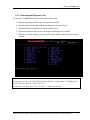
Procedure 2
Partition Check
Insert the bootable USB key, restart the computer with Esc key pressing down. and choose
boot from USB device. Perform the following checks:
Check 1
Type C: and press Enter. If you cannot change to drive C, go to Check 2. If you
can change to drive C, go to Check 3.
Check 2
Type FDISK and press Enter. Choose Display Partition Information from the
FDISK menu. If drive C is listed, go to Check 3. If drive C is not listed, return to
the FDISK menu and choose the option to create a DOS partition on drive C.
Restart the computer from the Toshiba MS-DOS system disk. If the problem still
exists, go to Procedure 3.
Check 3
If drive C is listed as active in the FDISK menu, go to Check 4. If drive C is not
listed as active, return to the FDISK menu and choose the option to set the active
partition for drive C. Restart the computer and then go to Procedure 3.
Check 4
Remove the USB key and restart the computer. If the problem still exists, go to
Procedure 3.
Check 5
Using the SYS command on the Toshiba MS-DOS system disk, install system
files on the HDD/SSD.
If the following message appears on the display, the system files have been
transferred to the HDD/SSD. Restart the computer. If the problem still exists, go
to Procedure 3.
System transferred
NOTE: If the computer is running Windows 2000, OSR2 or higher and the hard disk has
more than 512 MB capacity, the FDISK program will ask if you need support for
a partition larger than 2GB. Select Y for large partition support; however, be
sure to read the precaution regarding access by other operating systems.
2-24
[CONFIDENTIAL] Satellite M500/M505/M507 Maintenance Manual
2 Troubleshooting Procedures
Procedure 3
Format Check
The computer’s HDD/SSD is formatted using the low level format program and the MS-DOS
FORMAT program. To format the HDD/SSD, start with Check 1 below and perform the
other steps as required.
Check 1
Format the HDD/SSD and transfer system files using FORMAT C:/S/U. If the
following message appears on the display, the HDD/SSD is formatted.
Format complete
If an error message appears on the display, refer to the Toshiba MS-DOS Manual
for more information and perform Check 2.
Check 2
Using the Diagnostics Disk, format the HDD/SSD with a low level format option.
Refer to Chapter 3, Tests and Diagnostics for more information about the
diagnostic program.
If the following message appears on the display, the HDD/SSD low level format
is complete. Partition and format the HDD/SSD using the MS-DOS FORMAT
command.
Format complete
If you cannot format the HDD/SSD using the Tests and Diagnostic program, go to
Procedure 4.
Satellite M500/M505/M507 Maintenance Manual [CONFIDENTIAL]
2-25
2 Troubleshooting Procedures
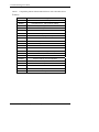
Procedure 4
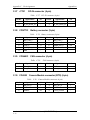
Diagnostic Test Program Execution Check
The HDD/SSD test program is stored in the Diagnostics Disk. Perform all of the HDD/SSD
tests in the Hard Disk Drive Test. Refer to Chapter 3, Tests and Diagnostics, for more
information about the HDD/SSD test program.
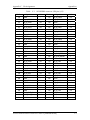
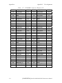
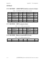
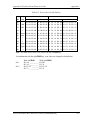
If an error is detected during the HDD/SSD test, an error code and status will be displayed.
Replace the HDD/SSD with a new one following the instructions in Chapter 4, Replacement
Procedures. The error codes and statuses are listed in Table 2-7. If an error code is not
generated or the problem still exists, go to Procedure 5.
Table 2-4 HDD/SSD error code and status
Code
Status
N0FH01
Can't Detect HDD when Boot Up/Detect wrong model name lf HD
N0FH02
HDD Data Error
N0FH03
HDD ATA/100 check error
N0FH04
HDD Type error
N0FH05
Hmonitor test fail
N0FH06
HDD Firmware version error
N0FH07
Shipping HDD restore ERROR
N0FH08
Shipping OS has been booted
N0FH09
Shipping OS version error
N0FH0A
shipping OS boot table error
N0FH0B
HDD Heating test Fail
N0FH0C
RAID function error
N0FH0D
2nd HDD function error
N0FH0E
SSD function error
Procedure 5
Connector Check and Replacement Check
The HDD/SSD may be disconnected, or the HDD/SSD or the main board may be damaged.
Disassemble the computer following the steps described in Chapter 4, Replacement
Procedures and perform the following checks:
Check 1
2-26
Make sure the HDD is firmly connected to CON6001 on the main board. Make
sure the SSD is firmly connected to CON6003 on the main board
[CONFIDENTIAL] Satellite M500/M505/M507 Maintenance Manual
2 Troubleshooting Procedures
If any of the connections are loose, reconnect firmly and repeat Procedure 1. If
there is still an error, go to Check 2.
Check 2
The HDD/SSD may be damaged. Replace it with a new one following the
instructions in Chapter 4, Replacement Procedures. If the problem still exists,
perform Check 3.
Check 3
The Main board may be damaged. Replace it with a new one following the
instructions in Chapter 4, Replacement Procedures.
Satellite M500/M505/M507 Maintenance Manual [CONFIDENTIAL]
2-27
2 Troubleshooting Procedures
2.6
Keyboard and Touch pad Troubleshooting
To determine if the computer’s keyboard or touch pad is functioning properly, perform the
following procedures. Start with Procedure 1 and continue with the other procedures as
instructed.
Procedure 1: Diagnostic Test Program Execution Check
Procedure 2: Connector Check and Replacement Check
Procedure 1
Diagnostic Test Program Execution Check
Execute the Keyboard Test in the Diagnostic Program. Refer to Chapter 3, Tests and
Diagnostics, for more information on how to perform the test program.
If an error occurs, go to Procedure 2. If an error does not occur, the keyboard is functioning
properly.
2-28
[CONFIDENTIAL] Satellite M500/M505/M507 Maintenance Manual
2 Troubleshooting Procedures
Procedure 2
Connector Check and Replacement Check
The keyboard, touch pad or sensor/switch board may be disconnected or damaged.
Disassemble the computer following the steps described in Chapter 4, Replacement
Procedures, and perform the following checks:
1. If the keyboard or AccuPoint malfunctions, start with Check 1.
2. If the touch pad malfunctions, start with Check 3.
3. If the power switch, InTouch button or Presentation button malfunctions, start with
Check 5.
Check 1
Make sure the keyboard cable is securely connected to CON4801 on the main
board.
If the connection is loose, reconnect firmly. If there is still an error, go to Check 2.
Check 2
The keyboard or its cable may be damaged. Replace it with a new one following
the instructions in Chapter 4, Replacement Procedures. If the problem still exists,
perform Check 5.
Check 3
Make sure the touch pad cable is firmly connected to M1tp_Con1 on the touch
pad board.
Satellite M500/M505/M507 Maintenance Manual [CONFIDENTIAL]
2-29
2 Troubleshooting Procedures
If the connection is loose, reconnect firmly. If there is still an error, go to Check 4.
Check 4
Check 5
2-30
The touch pad or the touch pad cable may be damaged. Replace it with a new one
following the instructions in Chapter 4, Replacement Procedures. If the problem
still exists, perform Check 5.
The main board may be damaged. Replace it with a new one following the
instructions in Chapter 4, Replacement Procedures.
[CONFIDENTIAL] Satellite M500/M505/M507 Maintenance Manual
2 Troubleshooting Procedures
2.7
Display Troubleshooting
This section describes how to determine if the computer’s display is functioning properly.
Start with Procedure 1 and continue with the other procedures as instructed.
Procedure 1: External Monitor Check
Procedure 2: Diagnostic Test Program Execution Check
Procedure 3: Connector Check and Cable Check
Procedure 4: Replacement Check
Procedure 1
External Monitor Check
Connect an external monitor and turn on the computer. If there is no problem on it, the
internal LCD may be defective. Go to Procedure 3. If there is any problem on the external
monitor, the main board may be defective. Go to Procedure 2.
Procedure 2
Diagnostic Test Program Execution Check
The Display Test program is stored on the computer’s Diagnostics disk. This program checks
the display controller on the main board. Connect the Diagnostics HDD, turn on the
computer and run the test. Refer to Chapter 3, Tests and Diagnostics for details. If an error is
detected, go to Procedure 3.
Procedure 3
Check 1
Connector Check and Cable Check
The LCD and Main board are connected by the LVDS cable. Check the
connections. The connectors may be disconnected or damaged. Disassemble the
computer following the steps described in Chapter 4, Replacement Procedures.
Satellite M500/M505/M507 Maintenance Manual [CONFIDENTIAL]
2-31
2 Troubleshooting Procedures
If the connection is loose, reconnect firmly and restart the computer. If there is still an error,
go to Procedure 4.
Procedure 4
Replacement Check
LCD module and main board are connected to display circuits. Any of these components
may be damaged. Refer to Chapter 4, Replacement Procedures, for instructions on how to
disassemble the computer and then perform the following checks:
Check 1
Make sure the LVDS cable is firmly connected to CON6201 on the main board.
If any of the connections are loose, reconnect firmly and repeat Procedure 1. If
there is still an error, go to Check 2.
Check 2
The LCD may be damaged. Replace it with a new one following the instructions
in Chapter 4, Replacement Procedures. If the problem still exists, perform Check
3.
Check 3
The Main board may be damaged. Replace it with a new one following the
instructions in Chapter 4, Replacement Procedures.
2-32
[CONFIDENTIAL] Satellite M500/M505/M507 Maintenance Manual
2 Troubleshooting Procedures
2.8
Optical Drive Troubleshooting
This section describes how to determine if the optical drive (DVD-ROM and DVD±R/±RW/RAM Drive) in the Slim Select Bay is functioning properly. Perform the steps below starting
with Procedure 1 and continue with the other procedures as required.
Procedure 1: Diagnostic Test Program Execution Check
Procedure 2: Connector Check and Replacement Check
Procedure 1
Diagnostic Test Program Execution Check
The DVD-ROM and DVD±R/±RW/-RAM Drive test program is stored on the Diagnostics
Disk.
For the test, prepare test Media.
Then connect the Diagnostics HDD, turn on the computer and run the test. Refer to Chapter
3, Tests and Diagnostics, for more information about the diagnostics test procedures.
If any errors occur while executing the DVD-ROM and DVD±R/±RW/-RAM Drive test, go
to Procedure 2.
Satellite M500/M505/M507 Maintenance Manual [CONFIDENTIAL]
2-33
2 Troubleshooting Procedures
Procedure 2
Connector Check and Replacement Check
The optical drive (DVD-ROM and DVD±R/±RW/-RAM Drive) is connected to the main
board. The connectors may be disconnected from the main board or may be damaged.
Disassemble the computer following the steps described in Chapter 4, Replacement
Procedures and perform the following checks:
Check 1
Make sure the drive to test is firmly connected to CON6002 on the main board.
If the connection is loose, reconnect firmly and repeat Procedure 1. If there is still
an error, go to Check 2.
Check 2
The drive may be defective or damaged. Replace the drive with a new one. If
there is still an error, go to Check 3.
Check 3
Replace the main board with a new one following the steps in Chapter 4,
Replacement Procedures.
2-34
[CONFIDENTIAL] Satellite M500/M505/M507 Maintenance Manual
2 Troubleshooting Procedures
2.9
Modem Troubleshooting
This section describes how to determine if the computer’s modem is functioning properly.
Perform the steps below starting with Procedure 1 and continuing with the other procedures
as required.
Procedure 1: Diagnostic Test Program Execution Check
Procedure 2: Connector Check and Replacement Check
Procedure 1
Diagnostic Test Program Execution Check
Insert the LAN/Modem test program in the USB key, turn on the computer and run the test.
Refer to Chapter 3, Tests and Diagnostics, for more information about the diagnostics test
procedures.
If any errors occur while executing the Sound/Modem/LAN test, go to Procedure 2.
Satellite M500/M505/M507 Maintenance Manual [CONFIDENTIAL]
2-35
2 Troubleshooting Procedures
Procedure 2
Connector Check and Replacement Check
The Modem is installed as an MDC (Modem Daughter Card). If the modem malfunctions,
there may be a bad connection between the MDC and the main board. Or the MDC, main
board or their connectors might be damaged.
Disassemble the computer following the steps described in Chapter 4, Replacement
Procedures and perform the following checks:
Check 1
Make sure the MDC is firmly connected to CON6501 by MDC cable on the main
board and the connector of the MDC.
If a connector is disconnected, connect it firmly and repeat Procedure 1. If the
modem is still not functioning properly, perform Check 2.
Check 2
The MDC may be defective or damaged. Replace it with a new one following the
steps in Chapter 4, Replacement Procedures. If the modem is still not functioning
properly, perform Check 3.
Check 3
The modem jack or MDC cable may be defective or damaged. Replace it with a
new one following the steps in Chapter 4, Replacement Procedures. If the modem
is still not functioning properly, perform Check 4.
Check 4
The main board may be defective or damaged. Replace it with a new one
following the steps in Chapter 4, Replacement Procedures.
2-36
[CONFIDENTIAL] Satellite M500/M505/M507 Maintenance Manual
2.10 LAN Troubleshooting
2 Troubleshooting Procedures
2.10 LAN Troubleshooting
This section describes how to determine if the computer’s LAN is functioning properly.
Perform the steps below starting with Procedure 1 and continue with the other procedures as
required.
Procedure 1: Diagnostic Test Program Execution Check
Procedure 1
Diagnostic Test Program Execution Check
Execute the LAN test program available as part of the LAN/Modem test program. Refer to
Chapter 3, Tests and Diagnostics for more information on how to perform the test program.
Satellite M500/M505/M507 Maintenance Manual [CONFIDENTIAL]
2-37
2 Troubleshooting Procedures
2.11 Wireless LAN Troubleshooting
This section describes how to determine if the computer’s Wireless LAN is functioning
properly. Perform the steps below starting with Procedure 1 and continuing with the other
procedures as required.
Procedure 1: Transmitting-Receiving Check
Procedure 2: Antenna Connection Check
Procedure 3: Replacement Check
Procedure 1
Transmitting-Receiving Check
Make sure the wireless switch of the computer is turned “On.” If it is not, please turn it on.
Refer to Chapter 3, Tests and Diagnostics for more information on how to perform the test
program.
Check 1
Execute test program for the wireless LAN function to check the transmittingreceiving function of the wireless LAN. You will need a second computer that can
communicate by the wireless LAN.
If the computer passes the test, the function is correctly working.
If the computer does not pass the test, perform Procedure 2.
2-38
[CONFIDENTIAL] Satellite M500/M505/M507 Maintenance Manual
2 Troubleshooting Procedures
Procedure 2
Antenna Connection Check
The wireless LAN wiring diagram is shown below:
Any of the connections may be disconnected. Disassemble the computer following the steps
described in Chapter 4, Replacement Procedures, and perform the following checks:
Check 1
Make sure the wireless LAN board is firmly connected to CON5701 on the main
board.
If the connector is disconnected, connect it firmly. If the wireless LAN board is
still not functioning properly, perform Check 2.
Check 2
Make sure the wireless LAN antenna cables are firmly connected to the wireless
LAN board.
If the wireless LAN antenna cables are disconnected, connect them firmly. If the
wireless LAN board is still not functioning properly, go to Procedure 3.
Satellite M500/M505/M507 Maintenance Manual [CONFIDENTIAL]
2-39
2 Troubleshooting Procedures
Procedure 3
Replacement Check
The wireless LAN antenna, wireless LAN board and the main board are connected to the
circuits. Any of these components may be damaged. Refer to Chapter 4, Replacement
Procedures, for instructions on how to disassemble the computer and then perform the
following checks:
Check 1
The wireless LAN board may be defective or damaged. Replace the board with a
new one following the steps in Chapter 4, Replacement Procedures. If the
problem still exists, perform Check 2.
Check 2
The wireless LAN antenna may be defective or damaged. Replace the antenna
with a new one following the steps in Chapter 4, Replacement Procedures. If the
problem still exists, perform Check 3.
Check 3
The main board may be defective or damaged. Replace the board with a new one
following the instructions in Chapter 4, Replacement Procedures and test the
display again.
2-40
[CONFIDENTIAL] Satellite M500/M505/M507 Maintenance Manual
2 Troubleshooting Procedures
2.12 Sound Troubleshooting
This section describes how to determine if the computer’s sound functions are functioning
properly. Perform the steps below starting with Procedure 1 and continuing with the other
procedures as required.
Procedure 1: Diagnostic Test Program Execution Check
Procedure 2: Connector Check
Procedure 3: Replacement Check
Procedure 1
Diagnostic Test Program Execution Check
Insert the Sound test program in the USB key, turn on the computer and run the test. Refer to
Chapter 3, Tests and Diagnostics, for details.
If an error is detected, go to Procedure 2.
Satellite M500/M505/M507 Maintenance Manual [CONFIDENTIAL]
2-41
2 Troubleshooting Procedures
Procedure 2
Connector Check
The sound function-wiring diagram is shown below:
Any of the connections may be disconnected. Disassemble the computer following the steps
described in Chapter 4, Replacement Procedures and perform the following checks:
If the stereo speakers do not work correctly, perform Check 1.
If the headphone does not work correctly, perform Check 2.
If the microphones do not work correctly, perform Check 3.
Check 1
If the stereo speakers do not work properly, the speaker cable may be
disconnected. Make sure the speaker cable is firmly connected to CON4101 on
the Main board. If the stereo speakers are still not functioning properly, go to
procedure 3.
Check 2
If the headphone does not work properly, the headphone cable may be
disconnected. Make sure the headphone cable is firmly connected to CON4201 on
the Main board. If the sound function still does not work properly, go to
procedure 3.
Check 3
If the microphones do not work properly, the external microphone cable may be
disconnected. When using the external microphone, make sure the external
microphone cable is firmly connected to CON4202 on the Main board. If the
microphones are still not functioning properly, go to procedure 3.
2-42
[CONFIDENTIAL] Satellite M500/M505/M507 Maintenance Manual
2 Troubleshooting Procedures
Procedure 3
Replacement Check >>>>
Check 1
If the stereo speakers do not sound properly, the right or left speaker may be
defective or damaged. Replace it with a new one. If the stereo speakers still do not
work properly, go to Check 4.
Check 2
If the headphone does not sound properly, the headphone jack may be defective or
damaged. Replace it with a new one. If the sound function still does not work
properly, go to Check 4.
Check 3
If the microphones do not work properly, the microphone cable may be defective
or damaged. Replace it with a new one. If the microphone still does not work
properly, go to Check 4.
Check 4
The Main board may be defective or damaged. Replace it with a new one.
Satellite M500/M505/M507 Maintenance Manual [CONFIDENTIAL]
2-43
2 Troubleshooting Procedures
2.16 SD Card Slot Troubleshooting
2.13 Card Reader Slot Troubleshooting
This section describes how to determine if the computer’s card reader functions are
functioning properly. Perform the steps below starting with Procedure 1 and continuing with
the other procedures as required.
Procedure 1: Check on Windows VISTA(TM)
Procedure 2: Connector Check and Replacement Check
Procedure 1
Check on Windows VISTA(TM)
Insert an MMC/SD/MS/MS(PRO) card into the slot. Check if the installed Windows
recognizes automatically the MMC/SD/MS/MS(PRO) card and the data in the
MMC/SD/MS/MS(PRO) card can be read.
If the card is not recognized or data are not read, go to Procedure 2.
Procedure 2
Connector Check and Replacement Check
The MMC/SD/MS/MS(PRO) card is connected to CON5001 on the Main board.
Check 1
The MMC/SD/MS/MS(PRO) card and the Main board may be disconnected.
Make sure the MMC/SD/MS/MS(PRO) card is firmly inserted to CON3301 on
the Main board. If not, insert it firmly. If the MMC/SD/MS/MS(PRO) card is still
not functioning properly, perform Check 2.
Check 2
The MMC/SD/MS/MS(PRO) card may be faulty. Replace it with a new one
following the step in Chapter 4 Replacement Procedures. If the problem continues,
perform Check 3.
Check 3
The Main board may be faulty. Replace it with a new one following the step in
Chapter 4 Replacement Procedures.
2-44
[CONFIDENTIAL] Satellite M500/M505/M507 Maintenance Manual
2 Troubleshooting Procedures
2.14 PCI Express Card Slot Troubleshooting
This section describes how to check PCI Express Card slot by inspecting a card with PCI
Express interface.
Procedure 1: Check on Windows VISTA(TM)
Procedure 2: Connector Check and Replacement Check
Procedure 1
Check on Windows VISTA(TM)
Insert a PCI Express Card into the slot. Check if the installed Windows recognizes
automatically the PCI Express Card.
If the card is not recognized, go to Procedure 2.
Procedure 2
Connector Check and Replacement Check
The PCI Express Card is connected to CON5401 on the Main board.
Check 1
The PCI ExpressCard and the Main board may be disconnected. Make sure the
PCI ExpressCard is firmly inserted to CON5401 on the Main board. If not, insert
it firmly. If the PCI ExpressCard is still not functioning properly, perform Check
2.
Check 2
The PCI ExpressCard may be faulty. Replace it with a new one following the step
in Chapter 4 Replacement Procedures. If the problem continues, perform Check
3.
Check 3
The Main board may be faulty. Replace it with a new one following the step in
Chapter 4 Replacement Procedures.
Satellite M500/M505/M507 Maintenance Manual [CONFIDENTIAL]
2-45
2 Troubleshooting Procedures
2-46
2.16 SD Card Slot Troubleshooting
[CONFIDENTIAL] Satellite M500/M505/M507 Maintenance Manual
2 Troubleshooting Procedures
2.15 Fingerprint Board(BTO) Troubleshooting
This section describes how to determine if the computer’s fingerprint board is functioning
properly. Perform the steps below starting with Procedure 1 and continuing with the other
procedures as required.
Procedure 1: Diagnostic Test Program Execution Check
Procedure 2: Connector Check and Replacement Check
Procedure 1
Diagnostic Test Program Execution Check
Insert the fingerprint board test program in the USB key, turn on the computer and run the
test. Refer to Chapter 3, Tests and Diagnostics, for more information about the diagnostics
test procedures.
If any errors occur while executing the fingerprint board test, go to Procedure 2.
Satellite M500/M505/M507 Maintenance Manual [CONFIDENTIAL]
2-47
2 Troubleshooting Procedures
Procedure 2
2.16 SD Card Slot Troubleshooting
Connector Check and Replacement Check
The fingerprint board is installed to the touchpad board. If the fingerprint board
malfunctions, there may be a bad connection between the fingerprint board and the touchpad
board. Or the fingerprint board or touchpad board might be damaged.
Disassemble the computer following the steps described in Chapter 4, Replacement
Procedures and perform the following checks:
Check 1
Make sure the fingerprint board is firmly connected to M1tp_J1 on the touchpad
board and the connector of the fingerprint board.
If a connector is disconnected, connect it firmly and repeat Procedure 1. If the
fingerprint board is still not functioning properly, perform Check 2.
Check 2
The fingerprint board may be defective or damaged. Replace it with a new one
following the steps in Chapter 4, Replacement Procedures. If the fingerprint
board is still not functioning properly, perform Check 3.
Check 3
The touchpad board may be defective or damaged. Replace it with a new one
following the steps in Chapter 4, Replacement Procedures.
2-48
[CONFIDENTIAL] Satellite M500/M505/M507 Maintenance Manual
2 Troubleshooting Procedures
2.16 Bluetooth(BTO) Troubleshooting
This section describes how to determine if the computer’s Bluetooth is functioning properly.
Perform the steps below starting with Procedure 1 and continuing with the other procedures
as required.
Procedure 1: Diagnostic Test Program Execution Check
Procedure 2: Connector Check and Replacement Check
Procedure 1
Diagnostic Test Program Execution Check
Insert the Bluetooth test program in the USB key, turn on the computer and run the test.
Refer to Chapter 3, Tests and Diagnostics, for more information about the diagnostics test
procedures.
If any errors occur while executing the Bluetooth test, go to Procedure 2.
Satellite M500/M505/M507 Maintenance Manual [CONFIDENTIAL]
2-49
2 Troubleshooting Procedures
Procedure 2
2.16 SD Card Slot Troubleshooting
Connector Check and Replacement Check
The Bluetooth is installed on the main board by Bluetooth cable. If the Bluetooth
malfunctions, there may be a bad connection between the Bluetooth and the main board. Or
the Bluetooth, main board or the Bluetooth cable might be damaged.
Disassemble the computer following the steps described in Chapter 4, Replacement
Procedures and perform the following checks:
Check 1
Make sure the Bluetooth is firmly connected to CON6501 by Bluetooth cable on
the main board and the connector of the Bluetooth.
If a connector is disconnected, connect it firmly and repeat Procedure 1. If the
Bluetooth is still not functioning properly, perform Check 2.
Check 2
The Bluetooth may be defective or damaged. Replace it with a new one following
the steps in Chapter 4, Replacement Procedures. If the Bluetooth is still not
functioning properly, perform Check 3.
Check 3
The Bluetooth cable may be defective or damaged. Replace it with a new one
following the steps in Chapter 4, Replacement Procedures. If the Bluetooth is still
not functioning properly, perform Check 4.
Check 4
The main board may be defective or damaged. Replace it with a new one
following the steps in Chapter 4, Replacement Procedures.
2-50
[CONFIDENTIAL] Satellite M500/M505/M507 Maintenance Manual
2 Troubleshooting Procedures
2.17 3G(BTO) Troubleshooting
This section describes how to determine if the computer’s 3G is functioning properly.
Perform the steps below starting with Procedure 1 and continuing with the other procedures
as required.
Procedure 1: Diagnostic Test Program Execution Check
Procedure 2: Connector Check and Replacement Check
Procedure 1
Diagnostic Test Program Execution Check
Insert the 3G test program in the USB key, turn on the computer and run the test. Refer to
Chapter 3, Tests and Diagnostics, for more information about the diagnostics test procedures.
If any errors occur while executing the 3G test, go to Procedure 2.
Satellite M500/M505/M507 Maintenance Manual [CONFIDENTIAL]
2-51
2 Troubleshooting Procedures
Procedure 2
2.16 SD Card Slot Troubleshooting
Connector Check and Replacement Check
The 3G is installed as an 3G card. If the 3G malfunctions, there may be a bad connection
between the 3G and the main board. Or the 3G or main board might be damaged.
Disassemble the computer following the steps described in Chapter 4, Replacement
Procedures and perform the following checks:
Check 1
Make sure the 3G is firmly connected to CON5601 on the main board and the
connector of the 3G.
If a connector is disconnected, connect it firmly and repeat Procedure 1. If the 3G
is still not functioning properly, perform Check 2.
Check 2
The 3G may be defective or damaged. Replace it with a new one following the
steps in Chapter 4, Replacement Procedures. If the 3G is still not functioning
properly, perform Check 3.
Check 3
The main board may be defective or damaged. Replace it with a new one
following the steps in Chapter 4, Replacement Procedures.
2-52
[CONFIDENTIAL] Satellite M500/M505/M507 Maintenance Manual
2 Troubleshooting Procedures
2.18 Camera(BTO) Troubleshooting
This section describes how to determine if the computer’s camera is functioning properly.
Perform the steps below starting with Procedure 1 and continuing with the other procedures
as required.
Procedure 1: Diagnostic Test Program Execution Check
Procedure 2: Connector Check and Replacement Check
Procedure 1
Diagnostic Test Program Execution Check
Insert the camera test program in the USB key, turn on the computer and run the test. Refer
to Chapter 3, Tests and Diagnostics, for more information about the diagnostics test
procedures.
If any errors occur while executing the camera test, go to Procedure 2.
Satellite M500/M505/M507 Maintenance Manual [CONFIDENTIAL]
2-53
2 Troubleshooting Procedures
Procedure 2
2.16 SD Card Slot Troubleshooting
Connector Check and Replacement Check
The camera is installed on the main board by camera cable. If the camera malfunctions, there
may be a bad connection between the camera and the main board. Or the camera, main board
or the camera cable might be damaged.
Disassemble the computer following the steps described in Chapter 4, Replacement
Procedures and perform the following checks:
Check 1
Make sure the camera is firmly connected to CON6202 by camera cable on the
main board.
If a connector is disconnected, connect it firmly and repeat Procedure 1. If the
camera is still not functioning properly, perform Check 2.
Check 2
The camera may be defective or damaged. Replace it with a new one following
the steps in Chapter 4, Replacement Procedures. If the camera is still not
functioning properly, perform Check 3.
Check 3
The camera cable may be defective or damaged. Replace the LCD cover with a
new one following the steps in Chapter 4, Replacement Procedures. If the camera
is still not functioning properly, perform Check 4.
Check 4
The main board may be defective or damaged. Replace it with a new one
following the steps in Chapter 4, Replacement Procedures.
2-54
[CONFIDENTIAL] Satellite M500/M505/M507 Maintenance Manual
3 Tests and Diagnostics
Chapter 3
Tests and Diagnostics
Satellite M500/M505/M507/M500D/M505D/M507D Maintenance Manual [CONFIDENTIAL]
3-1
3 Tests and Diagnostics
Chapter 3 Contents
Tests and Diagnostics ..................................................................................................... 3-3
3.0.1
Test menu ............................................................................................. 3-4
3.0.2
Executing the Diagnostic Test.............................................................. 3-5
3.0.3
Executing the Diagnostic Test.............................................................. 3-6
3.1
Model,BIOS and CPU Test .................................................................................... 3-8
3.1.1
CPU Test ................................................................................................................ 3-9
3.2
Check MAC Test .................................................................................................. 3-10
3.3
ACIN Test ............................................................................................................ 3-11
3.4
Temperature Test.................................................................................................. 3-12
3.5
Web camera Test .................................................................................................. 3-13
3.6
PAD Test .............................................................................................................. 3-14
3.7
LCDRGB Test ...................................................................................................... 3-16
3.8
VGA Test ............................................................................................................. 3-21
3.9
Audio Test ............................................................................................................ 3-22
3.10
Keyboard Test ...................................................................................................... 3-23
3.11
Memory Test ........................................................................................................ 3-25
3.12
Function TEST ..................................................................................................... 3-27
3.13
LEDALL Test....................................................................................................... 3-28
3.14
STORE Test [CD/DVD-ROM TEST] ................................................................. 3-29
3.15
LID Switch Test ................................................................................................... 3-30
3.16
MS CARD Test .................................................................................................... 3-31
3.17
SD CARD Test ..................................................................................................... 3-33
3.18
HDD Test ............................................................................................................. 3-35
3.19
BATTERY Test.................................................................................................... 3-36
3.20
Touch LED Test ................................................................................................... 3-37
3.21
HDD 3D Protection .............................................................................................. 3-38
3.22
Speaker Test ......................................................................................................... 3-44
3.12
Read and Write DMI information ........................................................................ 3-45
3.23
Auto Run .............................................................................................................. 3-48
3.0
Appendix: ............................................................................................................. 3-49
3-2
[CONFIDENTIAL]Satellite M500/M505/M507/M500D/M505D/M507D Maintenance Manual
3 Tests and Diagnostics
Tests and Diagnostics
This chapter explains how to use the Diagnostic Test programs to test the functions of the
computer’s hardware modules. The test program should be stored on an optical media disk or
a USB boot memory.
The test program menu will also consist of some programs which test the hardware function
or display the current information of the computer.
To execute the auto run will automatically run all the test programs.
NOTE: Before starting the diagnostics, be sure to follow these steps:
1. Check all cables are connected firmly.
2. Exit any application and close Windows.
3. Check if [All Devices] is selected in the “Device Configure” in SETUP
menu.
4. Set test PC SATA Controller Mode to “Compatibility” in BIOS.
4. After test, remember to set SATA Controller mode back to “AHCI”.
Satellite M500/M505/M507/M500D/M505D/M507D Maintenance Manual [CONFIDENTIAL]
3-3
3 Tests and Diagnostics
3.0.1 Test menu
The Test MENU consists of the following functions.
Please enter the item number to choose and execute the test item.
3-4
[CONFIDENTIAL]Satellite M500/M505/M507/M500D/M505D/M507D Maintenance Manual
3 Tests and Diagnostics
3.0.2 Executing the Diagnostic Test
To start the Test PROGRAM on CD-ROM, follow these steps:
1. Burn the test program ISO image to an optical media disk.
2. Insert the optical media disk with the test program into optical device.
3. Turn on the power, and choose boot from optical device.
4. System will automatically run the test program and display the test menu.
5. When the test menu displays, please enter the item number to choose and execute the
test item.
Note:
Please make sure to set test PC SATA Controller Mode to “Compatibility” in BIOS and set
SATA Controller Mode to “ACHI” after test.
If it fails in a test item, press “Ctrl+C” and “Y” back to main menu.
Satellite M500/M505/M507/M500D/M505D/M507D Maintenance Manual [CONFIDENTIAL]
3-5
3 Tests and Diagnostics
3.0.3 Executing the Diagnostic Test
To start the Test PROGRAM on USB boot disk, follow these steps:
1. Please prepare Toshiba PC of Windows VISTA OS.
2. Please copy the file for creating a USB-Bootable memory to PC.
The filename of four files and one folder to copy is shown below.
a)
b)
c)
d)
e)
f)
COMMAND.COM
Freedos.bss
FreeDOSMake.exe
KERNEL.SYS
Autoexec.bat
Folder (USBMakingFolder)
3. Please format USB-memory in FAT mode before creating USB-Bootable memory.
4. And when you create USB-Bootable memory, please use only one USB-memory.
5. Run “FreeDOSMake.exe”. You can create USB-Bootable memory.
6. Unzip and copy whole test program to USB memory, overwrite all files.
3-6
[CONFIDENTIAL]Satellite M500/M505/M507/M500D/M505D/M507D Maintenance Manual
3 Tests and Diagnostics
Please check the check box.
And then click START.
7. Turn on the Toshiba PC which need test, and choose boot from USB device.
8. System will automatically run the test program and display the test menu.
9. When the test menu displays, please enter the item number to choose and execute the test
item.
NOTE:
Please make sure to set test PC SATA Controller Mode to “Compatibility” in BIOS.
Satellite M500/M505/M507/M500D/M505D/M507D Maintenance Manual [CONFIDENTIAL]
3-7
3 Tests and Diagnostics
3.1 Model,BIOS and CPU Test
Note:
The screen will pause 10sec then turn to next step.
3-8
[CONFIDENTIAL]Satellite M500/M505/M507/M500D/M505D/M507D Maintenance Manual
3 Tests and Diagnostics
3.1.1 CPU Test
Check CPU spec same with your fixture
Check Front side bus speed is real (The speed does match that of BIOS setup)
This chapter shows how to use the Diagnostics to test the functions of the CPU speed, type
and CPU ID code.
3.1.1.1. Diagnostic name: CPU.EXE
Diagnostic Version: 2.10 or later version.
3.1.1. 2.Principle and how to use:
a. The CPU diagnostic consists of the following functions.
The CPU types, internal speed and CPU ID.
Read the CPU type, internal speed and CPU ID information from the related address and
check if the information is the same as the customer order.
b. Please refer to the illustration above to see the CPU information.
c. Type “CPU.exe /?” in the Free Dos prompt and you can see more details in the command
line to help you check related information.
Satellite M500/M505/M507/M500D/M505D/M507D Maintenance Manual [CONFIDENTIAL]
3-9
3 Tests and Diagnostics
3.2 Check MAC Test
Check MAC address with the label on the motherboard
This chapter shows how to use the Diagnostics to test the MAC address of the Ethernet
controller.
3.3.1. Diagnostic name: pg8168.exe
Diagnostic Version: 2.00 or later version.
3.3.2. Principle and how to use:
a. The pg8168 diagnostic consists of the following functions.
MAC Address read and checking function.
Command line:
Pg8168.exe /vmac
Read the MAC address from the Ethernet controller ROM and the MAC will appear on the
screen..
3-10
Manual
[CONFIDENTIAL]Satellite M500/M505/M507/M500D/M505D/M507D Maintenance
3 Tests and Diagnostics
3.3 ACIN Test
Please insert adopter then run this program. This subtest checks if the power port works
properly.
This chapter shows how to use the Diagnostics to test the ACIN functions.
3.3.1 Plug in the power test program will display PASS
3.3.2 Unplug the power to test the program will show Fail.
If it fails in a test item, press “Ctrl+C” and “Y” back to main menu.
Satellite M500/M505/M507/M500D/M505D/M507D Maintenance Manual [CONFIDENTIAL]
3-11
3 Tests and Diagnostics
3.4 Temperature Test
Please execute the Temperature Test from test menu.
Test program will show the current CPU temperature result on RIO_25Ch line.
Temperature Test will also check if system temperature is at 20∘ C ~ 80∘ C.
3-12
Manual
[CONFIDENTIAL]Satellite M500/M505/M507/M500D/M505D/M507D Maintenance
3 Tests and Diagnostics
3.5 Web camera Test
This program is to check webcamera ID.
Satellite M500/M505/M507/M500D/M505D/M507D Maintenance Manual [CONFIDENTIAL]
3-13
3 Tests and Diagnostics
3.6 PAD Test
Press both the Left and Right Buttons three times to see if they work properly.
This chapter shows how to use the Diagnostics to test the pointing device functions.
3.8.1. Diagnostic name: PS2.EXE
Diagnostic Version: 1.15 or later version.
3.8.2. Principle and how to use:
a. The PS2 diagnostic tests the following functions.
Right & left button, move function.
Move the cursor and click Left and Right button to ensure the pointing device is working
normally.
Command line: Ps2 – ta – ts – r 3 – l 3 – ae /tp2
-r <n> : At least “n” times to click right button for the right button testing. <n> means 1,2… depend
on user’s setting.
-l <n> : At least “n” times to click left button for the left button testing. <n> means 1,2… depend
on user’s setting.
3-14
Manual
[CONFIDENTIAL]Satellite M500/M505/M507/M500D/M505D/M507D Maintenance
3 Tests and Diagnostics
-t2 : Testing Left and Right button only.
-ae : Auto exit the program after the Left and Right button click time setting have reached the
setting.
/TP2 : PS2 mouse testing, no driver need.
b. Please refer to the illustration above to see the Touchpad test information.
c. Type “PS2.exe /?” in the Free Dos prompt and you can see more details in the command
line to help you check related information
Satellite M500/M505/M507/M500D/M505D/M507D Maintenance Manual [CONFIDENTIAL]
3-15
3 Tests and Diagnostics
3.7 LCDRGB Test
This subtest displays gradations for following modes. To change the mode, press Enter.
Command: video.exe –i /t 162 99
[Mode 101 640*480 8M]
[Mode 103 800*600 8M]
3-16
Manual
[CONFIDENTIAL]Satellite M500/M505/M507/M500D/M505D/M507D Maintenance
3 Tests and Diagnostics
[Mode 111 640*480 16M]
[Mode 114 800*600 16M]
Satellite M500/M505/M507/M500D/M505D/M507D Maintenance Manual [CONFIDENTIAL]
3-17
3 Tests and Diagnostics
3-18
Manual
[CONFIDENTIAL]Satellite M500/M505/M507/M500D/M505D/M507D Maintenance
3 Tests and Diagnostics
[Mode 105 1024*768 8M]
[Mode 117 1024*768 16M]
Satellite M500/M505/M507/M500D/M505D/M507D Maintenance Manual [CONFIDENTIAL]
3-19
3 Tests and Diagnostics
This chapter shows how to use the Diagnostics to test the LCD RGB/WB functions.
3.9.1. Diagnostic name: VIDEO.EXE
Diagnostic Version: 2.25.06 or later version.
3.9.2. Principle and how to use:
a. The VIDEO diagnostic tests following functions.
LCD test for R,G,B and BW.
Command line:
video -p -rc /RGB 111
video -p -gc /RGB 111
video -p -bc /RGB 111
-p: To set a pixel mode to display on the screen.
-rc | -gc | -bc: To set the color display on the screen.
VIDEO /F 117 A514
VIDEO /F 117 0000
VIDEO /F 117 05FE
To set the display mode White, Black and Blue shows on the screen.
b. Please refer to the illustration above to see the VIDEO test information.
c. Type “VIDEO.exe /?” in the Free Dos prompt and you can see more details in the
command line to help you check related information
3-20
Manual
[CONFIDENTIAL]Satellite M500/M505/M507/M500D/M505D/M507D Maintenance
3 Tests and Diagnostics
3.8 VGA Test
This chapter is part of the test card. This test focus on the function of VGA chip and VRAM.
Note:
It may occur a blue screen for serveral minutes before 3D test when using a USB disk to test.
Satellite M500/M505/M507/M500D/M505D/M507D Maintenance Manual [CONFIDENTIAL]
3-21
3 Tests and Diagnostics
3.9 Audio Test
3-22
Manual
[CONFIDENTIAL]Satellite M500/M505/M507/M500D/M505D/M507D Maintenance
3 Tests and Diagnostics
3.10 Keyboard Test
Press Fn +F12 to end the test
NOTE:
Press the Fn + F12 to end the test can only work after pressing all keys on the keyboard.
If there are some failure keys which cause the test can not complete, you can NOT use
Fn+ F12 to end test program. Please press “Ctrl + Shift” key (press Ctrl first then press
Shift). And then release “Ctrl + Shift” key (release Shift first then release Ctrl). This hot
key can help to exit the test program directly
This chapter shows how to use the Diagnostic to test the functions of the keyboard.
Diagnostic name: Keyboard.exe
Satellite M500/M505/M507/M500D/M505D/M507D Maintenance Manual [CONFIDENTIAL]
3-23
3 Tests and Diagnostics
Command: Keyboard.exe /r trsaeng.map trsaeng.xy trsaeng.cd
a. Please choose the different kind of keyboard language.
b. Display the keyboard on the screen to indicate to the operator checking whether or not
each key is correct.
c. Type each key to finish the program.
3-24
Manual
[CONFIDENTIAL]Satellite M500/M505/M507/M500D/M505D/M507D Maintenance
3 Tests and Diagnostics
3.11 Memory Test
This program will test the memory and shows you the total memory size.
Show the total memory size. Command: mm.exe – t 4 /s
This chapter shows how to use the Diagnostics to test the functions of the memory size,
speed and location.
3.2.2.1 Diagnostic name: SMBUS.EXE
Satellite M500/M505/M507/M500D/M505D/M507D Maintenance Manual [CONFIDENTIAL]
3-25
3 Tests and Diagnostics
Diagnostic Version: 1.37 or later version.
3.2.2.2 Principle and how to use:
a. The SMBUS diagnostic consists of the following functions.
Memory sizes, memory speed and memory location.
Command line: a-1. mm -t 4 /s %MSIZE%
“-t 3” defines where the memory size will be tested.
“/s %MSIZE%” set the memory size.
b. Please refer to the illustration above to see the memory information.
c. Type “SMBUS.exe /?” in the Free Dos prompt and you can see more details in the
command line to help you check related information
3-26
Manual
[CONFIDENTIAL]Satellite M500/M505/M507/M500D/M505D/M507D Maintenance
3 Tests and Diagnostics
3.12 Function TEST
Please enter “C” to select the function test. Test program will test several function and show
the test result one by one. (Command: functest.exe /T).
Satellite M500/M505/M507/M500D/M505D/M507D Maintenance Manual [CONFIDENTIAL]
3-27
3 Tests and Diagnostics
3.13 LEDALL Test
Test sequnce:
1. PWRBTN_LED
white
2. DC-IN LED
white
3. PWR_ULED_UP
orange
4. PWR_WLED
pink
5. BAT_ULED_UP
orange
6. BAT_WLED
pink
7. LOGO_LED
white
8. Light_GI_Led
white
9. KB_BL_CTRL
white
3-28
Manual
[CONFIDENTIAL]Satellite M500/M505/M507/M500D/M505D/M507D Maintenance
3 Tests and Diagnostics
3.14 STORE Test [CD/DVD-ROM TEST]
This Program will test if the CD/DVD-ROM works properly, please insert test CD before
test.
This chapter shows how to use the Diagnostics to test the ODD functions.
3.17.1. Diagnostic name: PSATA.EXE
3.17.2. Principle and how to use:
a. The PSATA diagnostic consists of the following functions.
CD/DVD type , CD/DVD F/W.
Command line:
psata -d 3 -rep _ /cm "TSSTcorpCDW/DVD_TS-L462D"
Check the Secondary master IDE device and check if the device name is the same as
“TSSTcorpCDW/DVD_TS-L462D.”
psata -d 3 -rep _ /cf "TO01"
Check the Secondary master IDE device and check if the device is F/W then check if the
F/W version is same as “TO01.”
b. Type “PSATA.exe /?” in the Free Dos prompt and you can see more details in the
command line to help you check related information.
Satellite M500/M505/M507/M500D/M505D/M507D Maintenance Manual [CONFIDENTIAL]
3-29
3 Tests and Diagnostics
3.15 LID Switch Test
Run the test using the instructions in the image below.
This chapter shows how to use the Diagnostics to test the LID functions.
3.18.1. Diagnostic name: PMC.EXE
Diagnostic Version: 2.05.
3.18.2. Principle and how to use:
a. The diagnostic of PMC detects whether the lid SW works or not.
After active LID function (close the upper cover) the program will read the EC (Embedded
Controller) controller then use the read data to check if the LID switch function is correct.
b. Type “PMC.exe /?” in the Free Dos prompt and you can see more details in the command
line to help you check related information.
3-30
Manual
[CONFIDENTIAL]Satellite M500/M505/M507/M500D/M505D/M507D Maintenance
3 Tests and Diagnostics
3.16 MS CARD Test
This chapter shows how to use the Diagnostics to test the card reader functions.
Satellite M500/M505/M507/M500D/M505D/M507D Maintenance Manual [CONFIDENTIAL]
3-31
3 Tests and Diagnostics
3.19.1. Diagnostic name: RMS2XX.EXE
Diagnostic Version: 1.02.
3.19.2. Principle and how to use:
Diagnostic provided by vendor which is an MS card test program that checks the MS card’s
read, write and protect function.
a. The diagnostic of RMS2XX detects MS card and read /write data.
3.19.3. Principle and how to use:
Copy data into the card and compare with the master file to see if the data matches.
3-32
Manual
[CONFIDENTIAL]Satellite M500/M505/M507/M500D/M505D/M507D Maintenance
3 Tests and Diagnostics
3.17 SD CARD Test
This chapter shows how to use the Diagnostics to test the card reader functions.
Satellite M500/M505/M507/M500D/M505D/M507D Maintenance Manual [CONFIDENTIAL]
3-33
3 Tests and Diagnostics
3.20.1. Diagnostic name: RSD.EXE
Diagnostic Version: 1.02.
3.20.2. Principle and how to use:
Diagnostic provided by vendor which is an SD card test program that checks the SD card’s
read, write and protect function.
a. The diagnostic of RSD detects SD card and read /write data.
3.20.3. Principle and how to use:
Copy data into the card and compare with the master file to see if the data matches.
3-34
Manual
[CONFIDENTIAL]Satellite M500/M505/M507/M500D/M505D/M507D Maintenance
3 Tests and Diagnostics
3.18 HDD Test
There are three items you can choose:
Satellite M500/M505/M507/M500D/M505D/M507D Maintenance Manual [CONFIDENTIAL]
3-35
3 Tests and Diagnostics
3.19 BATTERY Test
The battery test will provide the relate information of battery. This program can also test the
battery charge / discharge function.
You can also find the battery cycle count information on this battery.
NOTE:
Please connect the AC adapter to system in battery charge test.
Please disconnect the AC adapter from system in battery discharge test
3-36
Manual
[CONFIDENTIAL]Satellite M500/M505/M507/M500D/M505D/M507D Maintenance
3 Tests and Diagnostics
3.20 Touch LED Test
Hands touch the white box of three seconds, then next step
Satellite M500/M505/M507/M500D/M505D/M507D Maintenance Manual [CONFIDENTIAL]
3-37
3 Tests and Diagnostics
3.21 HDD 3D Protection
Place computer in five position as screen shows.
For Field inspection T&D, this program judges by sampling five kinds of data shown below.
No Item
Contents
1
Access
platform.
An access platform is leveling.
2
Test
Fixture
The Fixture which fixes PC by 60 degree inclination is used.
Vibration/shock doesn't take a PCB at the time of T&D inspection.
3
Test1
The display of a test program and the set method of PC are shown below.
Display of a Test Program
The portion which PC and Test-Fixture contact is green.
Set method of PC
Z
Upper
X
3-38
Manual
[CONFIDENTIAL]Satellite M500/M505/M507/M500D/M505D/M507D Maintenance
3 Tests and Diagnostics
Judgment
If all data is less than ranges, it will be OK.
4
Test2
The display of a test program and the set method of PC are shown below.
Display of a Test Program
Set method of PC
Rear
Upper
Judgment
If all data is less than ranges, it will be OK.
Satellite M500/M505/M507/M500D/M505D/M507D Maintenance Manual [CONFIDENTIAL]
3-39
3 Tests and Diagnostics
5
Test3
The display of a test program and the set method of PC are shown below.
Display of a Test Program
Set method of PC
Right
Upper
Judgment
If all data is less than ranges, it will be OK.
3-40
Manual
[CONFIDENTIAL]Satellite M500/M505/M507/M500D/M505D/M507D Maintenance
3 Tests and Diagnostics
6
Test4
The display of a test program and the set method of PC are shown below.
Display of a Test Program
Set method of PC
Front
Upper
Judgment
If all data is less than ranges, it will be OK.
Satellite M500/M505/M507/M500D/M505D/M507D Maintenance Manual [CONFIDENTIAL]
3-41
3 Tests and Diagnostics
7
Test5
The display of a test program and the set method of PC are shown below.
Display of a Test Program
Set method of PC
Left
Upper
Judgment
If all data is less than ranges, it will be OK.
8
Inspection
Judgment
If all data is less than ranges, it will be OK.
9
3-42
Manual
Setting
Calibration
data
When an inspection result is O.K., calibration at HPC.
[CONFIDENTIAL]Satellite M500/M505/M507/M500D/M505D/M507D Maintenance
3 Tests and Diagnostics
If the position is correct, it will show OK.
If the position is wrong, it will show NG.
Satellite M500/M505/M507/M500D/M505D/M507D Maintenance Manual [CONFIDENTIAL]
3-43
3 Tests and Diagnostics
3.22 Speaker Test
This program will test left channel, right channel and two wave files to test speaker function.
3-44
Manual
[CONFIDENTIAL]Satellite M500/M505/M507/M500D/M505D/M507D Maintenance
3 Tests and Diagnostics
3.12 Read and Write DMI information
This program could read and write below strings from/to DMI block.
1.
2.
3.
4.
5.
6.
Manufacture
Product Name
Version
Serial Number
Type 11
Type 12
DMI information:
Satellite M500/M505/M507/M500D/M505D/M507D Maintenance Manual [CONFIDENTIAL]
3-45
3 Tests and Diagnostics
Read Type 11:
Read Type 12:
Write Type 11(60 bytes):
Write Type 12 (64 bytes):
3-46
Manual
[CONFIDENTIAL]Satellite M500/M505/M507/M500D/M505D/M507D Maintenance
3 Tests and Diagnostics
Satellite M500/M505/M507/M500D/M505D/M507D Maintenance Manual [CONFIDENTIAL]
3-47
3 Tests and Diagnostics
3.23 Auto Run
Please enter “J” to select the auto run function. Test program will auto run all test items one
by one as following sequence.
3-48
Manual
[CONFIDENTIAL]Satellite M500/M505/M507/M500D/M505D/M507D Maintenance
3 Tests and Diagnostics
3.0 Appendix:
NO#
Equipment Description
Quantity
1
Test CD
2
Audio loopback jig
1
3
Memory Stick
1
4
SD Card
1
Remarks
Satellite M500/M505/M507/M500D/M505D/M507D Maintenance Manual [CONFIDENTIAL]
3-49
4
Replacement Procedures
Chapter 4
Replacement Procedures
SatelliteM500/M500D Maintenance Manual [CONFIDENTIAL]
4-1
4
Replacement Procedures
Chapter 4
4-2
4.1
General ...............................................................................................................6
4.2
Battery pack......................................................................................................14
4.3
Express card......................................................................................................16
4.4
HDD module ....................................................................................................17
4.5
Memory module ...............................................................................................21
4.6
Wireless LAN card ...........................................................................................23
4.7
Keyboard ..........................................................................................................26
4.8
Top cover........................................................................................................29
4.9
Bluetooth ........................................................................................................32
4.10
Power Button Board......................................................................................34
4.11
Fingerprint module........................................................................................36
4.12
Touchpad on-off board .................................................................................39
4.13
Main PCB......................................................................................................40
4.14
LAN Board....................................................................................................44
4.15
D/C IN Cable ................................................................................................46
4.16
Speaker..........................................................................................................48
4.17
Remove LCD Module...................................................................................50
4.18
CPU Heat sink/CPU......................................................................................52
4.19
VGA Card .....................................................................................................56
4.20
FAN...............................................................................................................57
4.21
LCD unit/Camera..........................................................................................59
[CONFIDENTIAL] SatelliteM500/M500D Maintenance Manual
4
Replacement Procedures
Figures
Figure 4-1 Removing the battery pack....................................................................14
Figure 4-2 Pressing the Express card......................................................................16
Figure 4-3 Removing the HDD cover.....................................................................17
Figure 4-4 Removing 4 screws securing HDD assembly .......................................18
Figure 4-5 Removing the HDD connector..............................................................18
Figure 4-6 Separating the HDD and HDD holder ..................................................19
Figure 4-7 Removing the first memory ..................................................................21
Figure 4-8 Removing the second memory..............................................................21
Figure 4-11
Removing the screws securing keyboard............................................26
Figure 4- 10
Removing screws and disconnecting wireless LAN antennas ...........24
Figure 4-9 Remove Wireless LAN card cover .......................................................23
Figure 4-12
Removing the keyboard cover ............................................................27
Figure 4-13
Removing the screws ..........................................................................27
Figure 4-14
Disconnecting the keyboard flexible and LED cable..........................27
Figure 4-15
Removing the screws on bottom case .................................................29
Figure 4-16
Removing the screws on top cover and separating the connector ......30
Figure 4-17
Removing top cover ............................................................................30
Figure 4-20
Removing the Power Button board .....................................................34
Figure 4-18
Removing Bluetooth ...........................................................................32
Figure 4-19
Disconnecting Bluetooth cable ...........................................................32
Figure 4-21
Removing the bracket .........................................................................36
SatelliteM500/M500D Maintenance Manual [CONFIDENTIAL]
4-3
4
Figure 4-22
Replacement Procedures
Removing the LED and Fingerprint Board.........................................37
Figure4-23 Separating fingerprint board assembly.................................................37
Figure 4-24 Removing screw securing touchpad on-off board ..............................39
Figure 4-25
Removing tapes and LVDS screw ......................................................40
Figure 4-26
Removing cables .................................................................................40
Figure 4-27
Removing screws secure the main PCB..............................................41
Figure 4-28 Removing ODD ..................................................................................41
4-4
Figure 4-29
Removing ODD bracket......................................................................42
Figure 4-30
Removing Main PCB ..........................................................................42
Figure 4-31
Removing screw securing LAN board................................................44
Figure 4-32
Removing screw securing bracket ......................................................46
Figure 4-33
Removing DC in cable ........................................................................46
Figure 4-34
Removing screws securing speaker ....................................................48
Figure 4-35
Removing tapes...................................................................................50
Figure 4-36
Removing LCD ...................................................................................50
Figure 4-37
Removing screws securing heat sink ..................................................52
Figure 4-38
Unlocking the CPU .............................................................................53
Figure 4-39
Installing the CPU ...............................................................................54
Figure 4-40
Applying new thermal pad ..................................................................55
Figure 4-41
Removing screws securing VGA Card ...............................................56
Figure 4-42
Removing screws securing FAN and disconnecting cable .................57
[CONFIDENTIAL] SatelliteM500/M500D Maintenance Manual
4
Replacement Procedures
Figure 4-43
Apply new thermal pad on the fan ......................................................58
Figure 4-44
Removing the bezel.............................................................................59
Figure 4-45
Removing the LCD unit ......................................................................60
Figure 4-46
Removing the LCD supports...............................................................61
Figure 4-47
Removing the LCD cable....................................................................62
Figure 4-48
Removing the Camera.........................................................................62
Figure 4-49 Disconnecting the CCD cable .............................................................62
SatelliteM500/M500D Maintenance Manual [CONFIDENTIAL]
4-5
4
Replacement Procedures
4.1 General
This section explains how to disassemble the computer and replace Field Replaceable
Units (FRUs). It may not be necessary to remove all the FRUs in order to replace one.
The chart below is a guide to which FRUs need to be removed in order to remove others.
Always start by removing the battery pack, next, optional items such as the optional
Express card and optional Media card, then follow the line on the chart to determine
which FRU you must remove first in order to repair the one you think is causing the
computer to operate improperly. Refer to the example at the bottom of the page.
How to see the
chart:
This chart shows
which unit(s) you
need to remove
in advance when
you replace one
unit.
Example:
When you want
to replace the
Main PCB, you
need to remove
units in the
hatched boxes
above the box in
which the Main
4-6
[CONFIDENTIAL] SatelliteM500/M500D Maintenance Manual
4
Replacement Procedures
Safety Precautions
Before you begin disassembly, read the following safety precautions and observe them
carefully as you work.
DANGER: 1) Always use the genuine battery that is authorized by Toshiba or
compatible with the unit. Since other battery packs have different
specifications, they may be incompatible with the unit, and may burst
or explode.
Never heat or disassemble the battery pack, as that could cause
leakage of alkaline solution. Never throw the battery pack into a
fire, as that could cause the battery pack to explode.
2) The power supply, FL inverter and other components carry high
voltages. If you need to turn on the power of a partially
disassembled computer to check its operation, be very careful not to
touch connectors or components, in order to avoid the risk of electric
shock.
Also, do not disassemble individual components in first-level
maintenance.
WARNING: 1) Turn off the power and disconnect the AC adaptor from the power
source, to avoid exposure to electric shock.
2) Batteries in the computer retain an electrical charge, so there is
danger of electrical shock even when the computer is disconnected
from an AC power source. Remove any metal jewelry or
accessories such as necklaces, bracelets or rings, in order to reduce
the risk of electric shock. Never work with wet or damp hands.
3) Be careful of edges and corners as these may cut.
CAUTION: 1) When you change a component, be sure the replacement component
meets the required specifications. Never use foreign parts, to avoid
any risk of damage to the computer.
2) To avoid any risk of short-circuit, fire or other internal damage,
never allow any metal objects such as screws or paper clips to fall
into the unit. Be sure to replace screws with the same size as those
removed. Make sure all screws are securely fastened. Loose
screws can cause short circuits, resulting in heat, smoke or fire.
3) Before lifting out a FRU or other component, make sure all cables to
the component have been disconnected, in order to reduce the risk of
accidental electric shock.
4) If you use AC power, be sure to use the cable that came with the
computer or one recommended by Toshiba.
5) Make sure that all replacement components meet the specifications
for the computer and that all cables and connectors are securely
fastened, in order to avoid the risk of electric shock.
6) Some parts inside the computer, such as the CPU and cooling
module, become very hot during operation. Conduct repair work
after they have cooled. Be careful around the CPU and cooling
module to avoid burns.
SatelliteM500/M500D Maintenance Manual [CONFIDENTIAL]
4-7
4
Replacement Procedures
Before You Begin
Look over the procedures in this section before you begin disassembling the computer.
Familiarize yourself with the disassembly and reassembly steps. Begin each procedure by
removing the AC adaptor and the battery pack as instructed in this section:
1. Do not disassemble the computer unless it is operating abnormally.
2. Use only the correct and approved tools.
3. Make sure the working environment is free from the following elements whether
you are using or storing the computer.
Dust and contaminates
Static electricity
Extreme heat, cold and humidity
4. Make sure the FRU you are replacing is causing the abnormal operation by
performing the necessary diagnostics tests described in this manual.
5. Do not perform any operations that are not necessary and use only the described
procedures for disassembling and installing FRUs in the computer.
6. After removing parts from the computer, place them in a safe place away from the
computer so they will not be damaged and will not interfere with your work.
7. You will remove and replace many screws when you disassemble the computer.
When you remove screws, make sure they are placed in a safe place and identified
with the correct parts.
8. When assembling the computer, make sure you use the correct screws to secure
the various pieces in place. Screw sizes are listed in their corresponding figures.
9. The computer contains many sharp edges and corners, so be careful not to injure
yourself.
10. After you have replaced a FRU, make sure the computer is functioning properly
by performing the appropriate test on the FRU you have fixed or replaced.
4-8
[CONFIDENTIAL] SatelliteM500/M500D Maintenance Manual
4
Replacement Procedures
Disassembly Procedures
The computer has three basic types of cable connectors:
Pressure Plate Connectors
Coaxial Cable Connectors
Normal Pin Connectors
To disconnect a Pressure Plate connector, lift up the tabs on either side of the connector’s
plastic pressure plate and slide the cable out of the connector. To connect the cable to a
Pressure Plate connector, make sure the pressure plate is fully lifted and slide the cable
into the connector. Secure the cable in place by pushing the sides of the pressure plate
down so the plate is flush with the sides of the connector. Gently pull on the cable to
make sure the cable is secure. If you pull out the connector, connect it again making
sure the connector’s pressure plate is fully lifted when you insert the cable.
Coaxial cables should be disconnected with an antenna coaxial disconnector.
Standard pin connectors are used with all other cables. These connectors can be
connected and disconnected by simply pulling them apart or pushing them together.
SatelliteM500/M500D Maintenance Manual [CONFIDENTIAL]
4-9
4
Replacement Procedures
Assembly Procedures
After you have disassembled the computer and fixed or repaired the problem that was
causing the computer to operate abnormally, you will need to reassemble the computer.
Install all the removed FRUs following the steps described in the corresponding sections
in this chapter.
While assembling the computer, remember the following general points:
Take your time, making sure you follow the instructions closely. Most
problems arise when you get in a hurry assembling the computer.
Make sure all cables and connectors are securely fastened.
Before securing the FRU or other parts, make sure that screws or the FRU will
not pinch any cables.
Check that all latches are closed securely in place.
Make sure all the correct screws are used to secure all FRUs. Using the
wrong screw can either damage the threads on the screw or the head of the
screw and may prevent proper seating of an FRU.
After installing a FRU in the computer, confirm that the FRU and the computer are
functioning properly.
4-10
[CONFIDENTIAL] SatelliteM500/M500D Maintenance Manual
4
Replacement Procedures
Tools and Equipment
The use of Electrostatic Discharge (ESD) equipment is very important for your safety and
the safety of those around you. Proper use of these devices will increase the success rate
of your repairs and lower the cost for damaged or destroyed parts. The following
equipment is necessary to disassemble and reassemble the computer:
One M2 point size 0 Phillips screwdriver
One M2.5/M3 point size 1 Phillips screwdriver
One screwdriver for stud screw
One 4 mm flat-blade screwdriver
Tweezers, to lift out screws that you cannot grasp with your fingers
ESD mats for the floor and the table you are working on
An ESD wrist strap or heel grounder
Anti-static carpeting or flooring
Air ionizers in highly static sensitive areas
Plastic card the size of a credit card
Antenna coaxial cable disconnector
SatelliteM500/M500D Maintenance Manual [CONFIDENTIAL]
4-11
4
Replacement Procedures
Screw Tightening Torque
When you fasten screws, be sure to follow the torque list below.
CAUTION:
Overtightening can damage components and screws; undertightening
can result in electrical shorts or other damage if screws or components
come loose.
NOTE:
M2
0.167 N·m (1.7 kgf·cm)
M2.5
0.294 N·m (3.0 kgf·cm)
M3
0.549 N·m (5.6 kgf·cm)
NOTE:
4-12
Toshiba recommends that you use an electric screwdriver for quick and easy
operations.
The computer contains several flathead screws. These screws have less
contact area with the screwdriver, so be careful to press firmly enough to
prevent the screwdriver from slipping out and damaging the screw head.
[CONFIDENTIAL] SatelliteM500/M500D Maintenance Manual
4
Replacement Procedures
Color of Screw Shaft
To avoid mistakes on the screw length, screw shafts are colored as follows:
Even number length screw:
brown
Odd number length screw:
white
Special length screw:
blue (Screws whose lengths are indicated to
one or more decimal places such as 2.5 mm or 2.8 mm.)
Marking of Screws on the Computer Body
To make maintenance of the computer easier, markings of the kinds of the screws
including the types and lengths of the screws are indicated on the computer body.
Kind of screws
Symbol
BIND screw
B
FLAT HEAD screw
F
SUPER THIN HEAD screw
S
TAPPING screw
T
Other screws
(Unique screws, STUD, etc.)
U
Examples:
6 mm BIND screw
B6
12 mm BIND screw
B12
4 mm FLAT HEAD screw
F4
(Indicates the screwed length in round number regardless the length of the stud.)
SatelliteM500/M500D Maintenance Manual [CONFIDENTIAL]
4-13
4
Replacement Procedures
4.2 Battery pack
Removing the Battery pack
To remove the battery pack, follow the steps below and refer to Figure 4-1.
CAUTION:
When handling battery packs, be careful not to short-circuit the
terminals. Also do not drop, hit or apply impact, do not scratch, break,
twist or bend the battery pack.
1. Turn off the power of the computer.
2. Disconnect the AC adaptor and other external devices from the computer.
3. Turn the computer face down.
4. Release the battery lock. Pull out the battery pack while sliding the battery
latch as shown in the following figure.
NOTE:
For environmental reasons, do not throw away a spent battery pack.
Battery latch
Battery lock
Figure 4-1 Removing the battery pack
4-14
[CONFIDENTIAL] SatelliteM500/M500D Maintenance Manual
4
Replacement Procedures
Installing the Battery pack
To install the battery pack, follow the steps below and refer to Figure 4-1.
CAUTION:
The battery pack is a lithium ion battery, which can explode if not
properly replaced, used, handled or disposed of. For environmental
reasons, collect the spent battery packs. Use only batteries recommended
by Toshiba for replacements.
NOTE:
Check the battery’s terminals visually. If they are dirty, wipe them clean with
a dry cloth.
1. Push the battery pack into the battery slot. Make sure the battery pack is installed
securely.
2. Slide the battery lock into the lock position.
3. Connect the AC adaptor and all other external devices to the computer.
SatelliteM500/M500D Maintenance Manual [CONFIDENTIAL]
4-15
4
Replacement Procedures
4.3 Express card
Removing the Express card
To remove the Express card, follow the steps below and refer to Figure 4-2 to 4-3.
CAUTION:
Before you remove the Express card, refer to the notebook’s
documentation and to your operating system documentation for proper
procedures and precautions.
1. Turn the computer face up.
2. Press the Express card pop the Express card out.
3. Grasp the Express card and pull it out.
Figure 4-2 Pressing the Express card
Installing the Express card
To install the Express card, follow the steps below and refer to Figure 4-2.
1. Insert the Express card into the card slot.
2. Push it carefully to ensure a firm connection.
4-16
[CONFIDENTIAL] SatelliteM500/M500D Maintenance Manual
4
Replacement Procedures
4.4
HDD module
CAUTION:
When handling the HDD, do not press the top surface as shown by the
arrow. Hold it by the sides.
Removing the HDD
To remove the HDD, follow the steps below and refer to Figure 4-4 to 4-10.
1. Turn the computer upside down.
2. Loosen the screw (with an e-ring) and remove the HDD cover, underneath which
there also installing the memory module.
Figure 4-3 Removing the HDD cover
3. Remove the following screws securing HDD module.
M23L
FLAT HEAD screw
4
SatelliteM500/M500D Maintenance Manual [CONFIDENTIAL]
4-17
4
Replacement Procedures
4. Pull the tab of the HDD assembly to remove it from the connector of the HDD
cable. Be careful not to damage the connector.
Figure 4-4 Removing 4 screws securing HDD assembly
NOTE:
The following steps describe how to disassemble the HDD assembly,
however, do not disassemble if the HDD is working properly.
5. Place the HDD assembly on a flat surface, remove the HDD connector and then
remove the following screws.
M34L FLAT HEAD screw
4
Figure 4-5 Removing the HDD connector
4-18
[CONFIDENTIAL] SatelliteM500/M500D Maintenance Manual
4
Replacement Procedures
6. Separate the HDD and HDD Holder.
CAUTION:
Do not apply pressure to the top or bottom of the HDD.
Figure 4-6 Separating the HDD and HDD holder
SatelliteM500/M500D Maintenance Manual [CONFIDENTIAL]
4-19
4
Replacement Procedures
Installing the HDD
To install the HDD, follow the steps below and refer to Figure 4-3 to 4-6.
CAUTION:
Do not hold the HDD by its top and bottom flat surfaces. It may
damage the HDD.
1. Seat the HDD in the HDD Holder and secure the following screws.
M23L
FLAT HEAD screw
4
2. Install the HDD connector.
3. Put the HDD into its slot and connect the HDD to the connector.
4. Secure them with the following screws.
M34L
CAUTION:
FLAT HEAD screw
4
Do not apply pressure to the center of the HDD pack.
It may damage
the HDD pack. Hold the HDD pack by its corners.
5. Set the HDD cover and secure it with the screw (with an e-ring).
4-20
[CONFIDENTIAL] SatelliteM500/M500D Maintenance Manual
4
Replacement Procedures
4.5 Memory module
Removing the Memory module
To remove the memory module, make sure the computer is in boot mode and powered
off, follow the steps below and refer to Figures 4-7 to 4-8.
1.
Press two latches outward and remove the first memory.
2.
Press two latches outward and remove the second memory.
Figure 4-7 Removing the first memory
Figure 4-8 Removing the second memory
SatelliteM500/M500D Maintenance Manual [CONFIDENTIAL]
4-21
4
Replacement Procedures
Installing the Memory module
To install the memory module, make sure that the computer is in boot mode and powered
off, follow the steps below and refer to Figures 4-7 to 4-8.
CAUTION: When installing only one memory module, be sure to insert it into slot .
Otherwise, the computer or the memory may not work properly.
Do not touch the connectors on the memory module or on the computer.
Dust and stains on the connectors may cause memory access problems.
1. Insert the second memory into the connector slantwise and press it to connect
firmly.
CAUTION: The power must be turned off when you insert a memory module.
Inserting a memory module with the power on might damage the module
or the computer itself.
Never press hard or bend the memory module.
2. When the power is turned on, the computer automatically checks the memory size.
Confirm that the new memory is detected correctly.
3. Insert the first memory into the connector slantwise and press it to connect firmly.
If the memory is not detected, check that it is connected correctly.
4-22
[CONFIDENTIAL] SatelliteM500/M500D Maintenance Manual
4
Replacement Procedures
4.6 Wireless LAN card
Removing the Wireless LAN card
To remove the wireless LAN card, make sure the computer is in boot mode and powered
off, follow the steps below and refer to Figures 4-9 to 4-10.
NOTE:
The wireless LAN card is an option.
CAUTION:
Do not try to remove the wireless LAN card with the computer turned
on. The computer or the wireless LAN card can be damaged. Do not
touch the connectors on the wireless LAN card module on the computer.
Debris on the connectors may cause wireless LAN card access problems.
1. Loosen the screw (with an e-ring) and remove the Wireless LAN card cover.
Figure 4-9 Remove Wireless LAN card cover
2. Remove one piece of tape and the following screw then the wireless antennas.
M23L
FLAT HEAD screw
SatelliteM500/M500D Maintenance Manual [CONFIDENTIAL]
2
4-23
4
Replacement Procedures
3. Disconnect the wireless LAN card from the connector on the main board. Be
careful not to damage the connector.
Figure 4- 10
4-24
Removing screws and disconnecting wireless LAN antennas
[CONFIDENTIAL] SatelliteM500/M500D Maintenance Manual
4
Replacement Procedures
Installing the Wireless LAN card
To install the wireless LAN card, make sure that the computer is in boot mode and
powered off, follow the steps below and refer to Figures 4-9 to 4-10.
CAUTION:
Be sure to switch the computer off before installing the wireless LAN
card. Otherwise, the computer or the wireless LAN card may be
damaged.
1. Insert the wireless LAN card into connector at an angle on the main board.
2. Gently push the wireless LAN card down and secure the wireless LAN card with the
following screw.
M23L
FLAT HEAD screw
2
3. Connect the wireless LAN antenna cables (white antenna cable should be
connected with the main connector; black antenna cable should be connected with
the Aux. connector) to the connectors on the wireless LAN card.
4. Paste the piece of tape.
SatelliteM500/M500D Maintenance Manual [CONFIDENTIAL]
4-25
4
Replacement Procedures
4.7 Keyboard
Removing the Keyboard
To remove the keyboard, follow the steps below and refer to Figures 4-11 to 4-14.
1. Remove the screws securing the bottom of the keyboard and the keyboard cover on
the bottom case.
M27L
FLAT HEAD screw
1
M23L
FLAT HEAD screw
2
M23L
Figure 4-11
Removing the screws securing keyboard
2. Turn the computer over and open the display.
3. Remove the Keyboard cover.
4-26
[CONFIDENTIAL] SatelliteM500/M500D Maintenance Manual
4
Replacement Procedures
Figure 4-12
Removing the keyboard cover
4. Remove the following screws securing keyboard.
M23L
FLAT HEAD screw
Figure 4-13
2
Removing the screws
5. Lift the keyboard upward a little and turn it face down on the palm rest.
6. Separate the keyboard flexible cable from connector and the keyboard LED cable
from the connector on the main board then remove the keyboard.
Figure 4-14
Disconnecting the keyboard flexible and LED cable
SatelliteM500/M500D Maintenance Manual [CONFIDENTIAL]
4-27
4
Replacement Procedures
Installing the Keyboard
To install the keyboard, follow the steps below and refer to Figures 4-11 to 4-14.
1. Place the keyboard face down on the top cover.
2. Connect the keyboard flexible cable to connector and the keyboard LED cable to
the connector on the main board.
3. Turn the keyboard face up and set it in place.
4. Secure the keyboard with following two screws.
M23L FLAT HEAD screw
2
5. Make sure that there is no gap between the keyboard and the edge of the top
cover.
6. Put the keyboard cover into its slot and press it.
7. Secure the keyboard and keyboard cover with three screws on the bottom case.
4-28
M27L
FLAT HEAD screw
1
M23L
FLAT HEAD screw
2
[CONFIDENTIAL] SatelliteM500/M500D Maintenance Manual
4
Replacement Procedures
4.8 Top cover
Removing the Top cover
To remove the Top cover, follow the steps below and refer to Figures 4-15 to 4-17.
1. Remove the following screws securing the bottom case to the toip case.
M2.55L FLAT HEAD screw
6
M24L
FLAT HEAD screw
6
M23L
FLAT HEAD screw
3
M27L
FLAT HEAD screw
3
M2X3L
M2.5X5
M2X4
M2.5X5
M2X4
M2X7
Figure 4-15 Removing the screws on bottom case
2. Turn the bottom case face up and remove the following screws securing top cover.
M24L
FLAT HEAD screw
5
3. Disconnect the connector on the main board
SatelliteM500/M500D Maintenance Manual [CONFIDENTIAL]
4-29
4
Replacement Procedures
Figure 4-16 Removing the screws on top cover and separating the connector
4. Separate the Top cover from the bottom case.
NOTE:
remove the top cover according to the direction of the arrow.
1
2
2
3
Figure 4-17
4-30
Removing top cover
[CONFIDENTIAL] SatelliteM500/M500D Maintenance Manual
4
Replacement Procedures
Installing the Top cover
To install the top case, follow the steps below and refer to Figures 4-15 to 4-17.
1. Install the Top cover on the bottom case.
2. Secure the following screws on the Top cover.
M24L
FLAT HEAD screw
5
3. Connect cable to connector on the main PCB, and turn the bottom case facedown.
4. Secure the following screws on the bottom case.
M2.55L
FLAT HEAD screw
6
M23L
FLAT HEAD screw
3
M24L
FLAT HEAD screw
6
M27L
FLAT HEAD screw
3
SatelliteM500/M500D Maintenance Manual [CONFIDENTIAL]
4-31
4
Replacement Procedures
4.9 Bluetooth
Removing the Bluetooth
To remove the Bluetooth, follow the steps below and refer to Figures 4-18 to 4-19.
1.
2.
3.
Remove two pieces of tape.
Take the bluetooh away from the top cover.
Remove the mylar on the fingerprint board.
Mylar
Tap
Figure 4-18
4.
Separate the cable from the connector according to the direction of the arrow.
Figure 4-19
4-32
Removing Bluetooth
Disconnecting Bluetooth cable
[CONFIDENTIAL] SatelliteM500/M500D Maintenance Manual
4
Replacement Procedures
Installing the Bluetooth
To install the Bluetooth, follow the steps below and refer to Figures 4-18 to 4-19.
1. Connect the cable to the Bluetooth.
2. Place the Bluetooth to the top cover.
3. Paste the tape and the mylar.
SatelliteM500/M500D Maintenance Manual [CONFIDENTIAL]
4-33
4
Replacement Procedures
4.10 Power Button Board
Removing the Power Button Board
To remove the power button board, follow the steps below and refer to Figures 4-20
Remove the following two screws and remove the board.
M23L
FLAT HEAD screw
Figure 4-20
4-34
2
Removing the Power Button board
[CONFIDENTIAL] SatelliteM500/M500D Maintenance Manual
4
Replacement Procedures
Installing the Power Button Board
To install the power button board, follow the steps below and refer to Figures 4-20.
1. Install the Power Button board on the top cover.
2. Secure the following screws on the Top cover.
M23L
FLAT HEAD screw
2
SatelliteM500/M500D Maintenance Manual [CONFIDENTIAL]
4-35
4
Replacement Procedures
4.11 Fingerprint module
Removing the fingerprint module
To remove the fingerprint module, follow the steps below and refer to Figures 4-21 to
4-23.
1.
Disconnect the cable.
2.
Remove the following screws then remove the bracket.
M23.5L
FLAT HEAD screw
4
M23L
FLAT HEAD screw
2
M2X3
Figure 4-21
3.
Remove the following screws and then take the fingerprint and led board away
M23.5L
4-36
Removing the bracket
FLAT HEAD screw
4
[CONFIDENTIAL] SatelliteM500/M500D Maintenance Manual
4
Replacement Procedures
Figure 4-22
4.
Removing the LED and Fingerprint Board
Separating fingerprint board assembly
Figure4-23 Separating fingerprint board assembly
SatelliteM500/M500D Maintenance Manual [CONFIDENTIAL]
4-37
4
Replacement Procedures
Installing the LED board
To install the LED board, follow the steps below and refer to Figures 4-21 to 4-23.
1. Securing the board.
2. Install the LED board and the Fingerprint Board on the top cover.
3. Secure the following screws on the Top cover.
M23.5L
FLAT HEAD screw
4
4. Install the bracket then securing the following screws.
M23.5L
FLAT HEAD screw
4
M23L
FLAT HEAD screw
2
5. Connect the cable to the board.
4-38
[CONFIDENTIAL] SatelliteM500/M500D Maintenance Manual
4
Replacement Procedures
4.12 Touchpad on-off board
Removing the touchpad on-off board
To remove the touchpad on-off board follow the steps below and refer to Figures 4-24.
1. Remove screws securing the touchpad on-off board then remove the board
M23L
Figure 4-24
1
FLAT HEAD screw
Removing screw securing touchpad on-off board
Installing the Touchpad on-off board
To install the touchpad on-off board, follow the steps below and refer to Figures 4-24.
1. Install the touchpad on-off board on the top cover, securing the following screws.
M23L
FLAT HEAD screw
1
SatelliteM500/M500D Maintenance Manual [CONFIDENTIAL]
4-39
4
Replacement Procedures
4.13 Main PCB
Remove the main PCB
To remove the main PCB, follow the steps below and refer to Figures 4-25 to 4-30.
1. Remove 7 pieces of tape and the LVDS screw.
M2X2.5
FLAT HEAD screw
1
2. Remove cables on the main PCB.
Figure 4-25
Removing tapes and LVDS screw
Figure 4-26
4-40
Removing cables
[CONFIDENTIAL] SatelliteM500/M500D Maintenance Manual
4
Replacement Procedures
3. Remove the following screws.
M2X3
FLAT HEAD screw
4
M2X4
FLAT HEAD screw
6
M1.6 X2.5 FLAT HEAD screw
1
4. Remove the ODD bracket and battery bracket.
M2X3L
M1.6X2.5L
Figure 4-27 Removing screws secure the main PCB
5. Remove the ODD module.
Figure 4-28 Removing ODD
6. Remove the following screws and take the ODD bracket away.
SatelliteM500/M500D Maintenance Manual [CONFIDENTIAL]
4-41
4
M22.5L
FLAT HEAD screw
Figure 4-29
Replacement Procedures
2
Removing ODD bracket
7. Lift the main PCB on the right side then remove it from the bottom case.
Figure 4-30
4-42
Removing Main PCB
[CONFIDENTIAL] SatelliteM500/M500D Maintenance Manual
4
Replacement Procedures
Installing the main PCB
To install the main PCB, follow the steps below and refer to Figures 4-25 to 4-30.
1. Securing the bracket to the ODD.
M22.5L
2
FLAT HEAD screw
2. Place the Main PCB to the bottom case
3. Install the ODD to the Main PCB
4. Secure the main PCB to the bottom case using the following screws.
M2X3
FLAT HEAD screw
4
M2X3
FLAT HEAD screw
6
M1.6 X2.5 FLAT HEAD screw
1
5. Connector the cable to the main PCB.
6. Securing the LVDS cable.
M2X2.5
FLAT HEAD screw
1
7. Paste 7 pieces of tape.
SatelliteM500/M500D Maintenance Manual [CONFIDENTIAL]
4-43
4
Replacement Procedures
4.14 LAN Board
Remove the LAN board
To remove the LAN Board, follow the steps below and refer to Figures 4-31.
1. Remove following screw securing the LAN board.
M24L
FLAT HEAD screw
1
2. Remove the LAN board.
Figure 4-31
Removing screw securing LAN board
Installing the main PCB
To install the main PCB, follow the steps below and refer to Figures 4-31.
1. Install the LAN board.
2. Securing the LAN board with following screw.
M24L
4-44
FLAT HEAD screw
1
[CONFIDENTIAL] SatelliteM500/M500D Maintenance Manual
4
Replacement Procedures
SatelliteM500/M500D Maintenance Manual [CONFIDENTIAL]
4-45
4
Replacement Procedures
4.15 D/C IN Cable
Remove D/C in cable
To remove the D/C in cable, follow the steps below and refer to Figures 4-32.
1. Remove the black mylar.
2. Remove following screw securing the bracket.
M24L
FLAT HEAD screw
1
3. Remove the bracket.
Figure 4-32
Removing screw securing bracket
4. Remove the DC in cable.
Figure 4-33 Removing DC in cable
4-46
[CONFIDENTIAL] SatelliteM500/M500D Maintenance Manual
4
Replacement Procedures
Installing the AC Power cable
To install the D/C in cable, follow the steps below and refer to Figures 4-32 to 4-33.
1. Install the D/C in cable.
2. Install the bracket and securing the following screw.
M24L
FLAT HEAD screw
1
3. Paste the mylar.
SatelliteM500/M500D Maintenance Manual [CONFIDENTIAL]
4-47
4
Replacement Procedures
4.16 Speaker
Remove the speaker
To remove the Speaker, follow the steps below and refer to Figures 4-57.
1. Remove the following screws securing the speaker.
M22L
Stand off screw
5
2. Remove the speaker from the bottom case.
Figure 4-34
4-48
Removing screws securing speaker
[CONFIDENTIAL] SatelliteM500/M500D Maintenance Manual
4
Replacement Procedures
Installing the speaker
To install the speaker, follow the steps below and refer to Figures 4-34.
1. Install the speaker.
2. Securing the following screw.
M22L
Stand off screw
5
SatelliteM500/M500D Maintenance Manual [CONFIDENTIAL]
4-49
4
Replacement Procedures
4.17 Remove LCD Module
To remove the LCD module, follow the steps below and refer to Figures 4-35 to 4-36.
1. Remove 6 pcs of tapes
Figure 4-35
Removing tapes
2. Remove the following three screws securing the hinge.
M2.55L
FLAT HEAD screw
4
3. Remove the LCD moduls
Figure 4-36 Removing LCD
4-50
[CONFIDENTIAL] SatelliteM500/M500D Maintenance Manual
4
Replacement Procedures
Installing LCD Module
To install the LCD module, follow the steps below and refer to Figures 4-35 to 4-36.
1. Install the LCD Module and securing the hinge with following screws.
M2.55L
FLAT HEAD screw
4
2. Arrange the cable.
3. Paste the tapes on the bottom case.
SatelliteM500/M500D Maintenance Manual [CONFIDENTIAL]
4-51
4
Replacement Procedures
4.18 CPU Heat sink/CPU
Removing the CPU Heat sink
To remove the heat sink, follow the steps below and refer to Figures 4-37 to 4-38.
CAUTION: 1) The CPU can become very hot during operation. Be sure to let it
cool before starting repair work.
2) When you remove the CPU, replace the thermal pad on the bottom
of heat sink with a new one before installing.
1. Turn the main PCB over and remove the following screws securing the CPU heat
sink and remove it.
M23L
FLAT HEAD screw
Figure 4-37
CAUTION:
6
Removing screws securing heat sink
Remove the screws in the order of mark “6”,”5”,“4”,“3”, “2” and
“1” on the CPU holder.
4-52
[CONFIDENTIAL] SatelliteM500/M500D Maintenance Manual
4
Replacement Procedures
2. Unlock the CPU by turning the cam counterclockwise on the CPU socket 180
degrees using a flat-blade screwdriver.
Figure 4-38
Unlocking the CPU
3. Remove the CPU.
CAUTION:
When removing the CPU, lift it straight up. Otherwise, pins on the CPU
may be damaged.
SatelliteM500/M500D Maintenance Manual [CONFIDENTIAL]
4-53
4
Replacement Procedures
Install the CPU heat sink/CPU.
To install the CPU heat sink/CPU, follow the steps below and refer to Figures 4-39 to
4-41.
1. Make sure the cam is in the open position.
2. Seat the CPU in the CPU socket. Make sure the direction and position of CPU is
correct to avoid damaging pins on the CPU.
CAUTION: Place the CPU as shown below. (Pay attention to the position of the
triangle mark on the CPU.)
3. Secure the CPU by turning the cam on the CPU socket 180 degrees clockwise with a
flat-blade screwdriver (in the order shown in the figure below).
Figure 4-39
Installing the CPU
4. Apply new thermal pad on the heat sink as shown in the following figure. Stick the
thermal pad on heat sink follow the mark. (Be sure to clean off all old pad before
applying new thermal pad).
4-54
[CONFIDENTIAL] SatelliteM500/M500D Maintenance Manual
4
Replacement Procedures
H000013080
H000013080
Figure 4-40 Applying new thermal pad
5. Install the CPU heat sink
6. Secure the CPU heat sink with the following screws in the numbered order as shown
on the holder.
M23L
FLAT HEAD screw
6
SatelliteM500/M500D Maintenance Manual [CONFIDENTIAL]
4-55
4
Replacement Procedures
4.19 VGA Card
Removing the VGA Card
To remove the VGA card, follow the steps below and refer to Figures 4-42.
1. Remove the following screws securing the VGA.
M23L
FLAT HEAD screw
2
2. Remove the VGA Card from the slot at the pop-up angle
Figure 4-42
Removing screws securing VGA Card
Install the VGA Card.
To install the VGA Card, follow the steps below and refer to Figures 4-42.
1. Insert the VGA Card into connector at an angle about 45
2. Secure the VGA Card with the following screws.
M23L
4-56
FLAT HEAD screw
2
[CONFIDENTIAL] SatelliteM500/M500D Maintenance Manual
4
Replacement Procedures
4.20 FAN
Removing the Fan
To remove the Fan, follow the steps below and refer to Figures 4-43.
1. Remove the following three screws securing the fan.
M24L
FLAT HEAD screw
3
2. Disconnect the cable from the board.
Figure 4-43
Removing screws securing FAN and disconnecting cable
3. Take the FAN away.
SatelliteM500/M500D Maintenance Manual [CONFIDENTIAL]
4-57
4
Replacement Procedures
Install the FAN.
To install the FAN, follow the steps below and refer to Figures 4-43 to 4-44.
1. Apply new thermal pad on the fan as shown in the following figure. Stick the
thermal pad on fan follow the mark. (Be sure to clean off all old pad before
applying new thermal pad).
H000013110
Figure 4-44
Apply new thermal pad on the fan
2. Install the Fan to the main board.
3. Secure the Fan with the following screws.
M24L
FLAT HEAD screw
3
4. Connect the cable.
4-58
[CONFIDENTIAL] SatelliteM500/M500D Maintenance Manual
4
Replacement Procedures
4.21 LCD unit/Camera
Removing the unit/Camera
To remove LCD unit/Camera, follow the steps below and refer to Figures 4-45 to 4-50.
1. Remove the two tape and the following two screws securing the panel.
M2.55L
FLAT HEAD screw
2
2. Remove the panel according to the direction of the arrow
Caution: Please be careful to not break LCD cover glass when LCD unit is
disassembled and assembled. Please refer to video file how to avoid breaking
LCD cover glass when LCD unit is disassembled and assembled.
3
2
1
3
Figure 4-45
Removing the bezel
SatelliteM500/M500D Maintenance Manual [CONFIDENTIAL]
4-59
4
Replacement Procedures
3. Remove the tape and the screws securing LCD unit then remove the LCD unit
M2.54L
FLAT HEAD screw
Figure 4-46
6
Removing the LCD unit
NOTE: For environmental reasons, do not throw away a malfunctioning LCD unit (or
FL). Please follow local ordinances or regulations for its disposal.
4-60
[CONFIDENTIAL] SatelliteM500/M500D Maintenance Manual
4
Replacement Procedures
4.
Remove the following screws securing the LCD supports and then remove them.
M22.5L
FLAT HEAD screw
Figure 4-47
6
Removing the LCD supports
5. Remove one piece of glass tape on LCD cable connector.
SatelliteM500/M500D Maintenance Manual [CONFIDENTIAL]
4-61
4
Replacement Procedures
6. Disconnect LCD cable from the connector and remove the cable.
Glass tape
Figure 4-48
Removing the LCD cable
7. Remove the Camera from the top case and disconnect the CCD cable from the
camera.
Figure 4-49
Removing the Camera
Figure 4-50 Disconnecting the CCD cable
4-62
[CONFIDENTIAL] SatelliteM500/M500D Maintenance Manual
4
Replacement Procedures
Installing the LCD unit / Camera
To install the LCD unit / Camera, follow the steps below and refer to Figures 4-45 to
4-50.
1. Connect the CCD cable to the Camera.
2. Install the camera to the top case.
3. Connect the LCD cable to the LCD unit
4. Secure one piece of glass tape on LCD cable connector.
5. Seat two LCD supports on the LCD and secure them with the following screws.
M22.5L FLAT HEAD screw
6
CAUTION: When installing the LCD support, do not mistake the left for the right
and vice versa. “L” for the left, “R” for the right and “UP” for the up of
the bracket are marked on the bracket.
6. Seat the LCD unit on the display cover.
CAUTION:
Please be careful to not leave dust and fingerprint on LCD cover glass
when LCD unit is disassembled and assembled. Please refer to video file how to avoid
dust and fingerprint on LCD cover glass when LCD unit is disassembled and
assembled.
7. Secure the following screws to attach the LCD unit.
M2.55L FLAT HEAD screw
6
8. Secure the LCD panel with the following screws.
M2.55L
FLAT HEAD screw
2
9. Replace the two pieces of tape to the hole of screw.
SatelliteM500/M500D Maintenance Manual [CONFIDENTIAL]
4-63
Appendix A Handling the LCD Module
Appendix A
Appendices
P
Appendix A Handling the LCD Module
Precautions for handling the LCD module
The LCD module can be easily damaged during assembly or disassembly. Observe the
following precautions when handling the LCD module:
1. When installing the LCD module in the LCD cover, be sure to seat it so that it is
properly aligned and maximum visibility of the display is maintained.
2. For the LCD module, be careful to align the four holes at the right side and left side
of the LCD module with the corresponding holes in the LCD cover before securing
the module with four screws.
Do not force the module into place, because stress can affect its performance.
Also, the panel’s polarized surface is easily scarred, so be carefully when handling it.
Satellite M500/M505/M507 Maintenance Manual [CONFIDENTIAL]
A-1
Appendices
Appendix A Handling the LCD Module
3. If the panel’s surface gets dirty, wipe it with cotton or a soft cloth. If it is still dirty,
try breathing on the surface to create a light condensate and wipe it again.
If the surface is very dirty, we recommend a CRT cleaning agent. Apply the agent to
a cloth and then wipe the panel’s surface. Do not apply cleanser directly to the panel.
4. If water or other liquid is left on the panel’s surface for a long period, it can change
the screen’s tint or stain it. Be sure to quickly wipe off any liquid.
A-2
[CONFIDENTIAL] Satellite M500/M505/M507 Maintenance Manual
Appendix A Handling the LCD Module
Appendices
5. Glass is used in the panel, so be careful not to drop it or let it strike a hard object,
which could cause breakage or cracks.
6. CMOS-LSI circuits are used in the module, so guard against damage from
electrostatic discharge. Be sure to wear a wrist or ankle ground when handling the
module.
Satellite M500/M505/M507 Maintenance Manual [CONFIDENTIAL]
A-3
Appendices
Appendix A Handling the LCD Module
7. Do not expose the module to direct sunlight or strong ultraviolet rays for long
periods.
8. Do not store the module at temperatures below specifications. Cold can cause the
liquid crystals to freeze, lose their elasticity or otherwise suffer damage.
A-4
[CONFIDENTIAL] Satellite M500/M505/M507 Maintenance Manual
Appendix A Handling the LCD Module
Appendices
9. Do not disassemble the LCD module. Disassembly can cause malfunctions.
10. If you transport the module, do not use packing material that contains epoxy resin
(amine) or silicon glue (alcohol or oxime). These materials can release gas that can
damage the panel’s polarization.
Satellite M500/M505/M507 Maintenance Manual [CONFIDENTIAL]
A-5
Appendix B Board Layout
Appendices
Appendix B Board Layout
B.1
Main Board Front View
Figure B-1 Main board layout (front)
Satellite M500/M50D/M507 Maintenance Manual [CONFIDENTIAL]
B-1
Appendices
Appendix B Board Layout
Table B-1 Main board connectors (front)
Number
CON6202
Camera / Int. MIC connector
CON3701
LVDS connector
CON6503
Power button connector
CON6601
FUNCTION BRD connector
CON6201
TouchPanel connector
CON4801
KB connector
CON5602
SIM card slot
CON5601
Mini card connector
CON6701
LAN BRD connector
CON4803
Keyboard LED connector
CON4804
TP ON/OFF connector
CON6204
FELICA connector
CON6203
Blue tooth connector
CON4802
Touch Pad connector
CON4101
Internal speaker connector
CON5401
New Card slot
CON6501
Modem connector
J7701
B-2
Name
DC IN connector
[CONFIDENTIAL] Satellite M500/M505/M507 Maintenance Manual
Appendix B Board Layout
B.2
Appendices
Main Board Back View
Figure B-2 Main board layout (back)
Satellite M500/M505/M507 Maintenance Manual [CONFIDENTIAL]
B-3
Appendices
Appendix B Board Layout
Table B-2 Main board connectors (back)
Number
Name
CBT_CON1 (HOT BAR)
B-4
FUNCTION BRD connector
CON3801
RGB connector
CON4901
FAN connector
CON7701
Battery Connector
CON6502
DEBUG CARD connector
CON6001
HDD connector
CON6002
ODD connector
CON6003
SSD connector
CON2101
Memory slot
CON2201
Memory slot
CON5501
Mini card connector
CON0701
AMD HDT Debug connector
CON3501
Graphics MXM connector
CON5701
Mini card connector
CON5001
Media Card slot
CON3901
HDMI connector
CON6107
eSATA / USB Combo connector
CON6106
USB connector
CON5101
1394 connector
CON4202
MIC JACK
CON4201
HP/ SPDIF JACK
[CONFIDENTIAL] Satellite M500/M505/M507 Maintenance Manual
Appendix B Board Layout
B.3
Appendices
LAN Board Front and Back View
(Front)
(Back)
Figure B-3 LAN Board layout (front/back)
Table B-3 LAN Board connectors (front/back)
Number
Name
MLCON301
RJ45 / FJ11 JACK
MLCON103
USB JACK
MLCON101 (HOT BAR)
LAN board interface
Satellite M500/M505/M507 Maintenance Manual [CONFIDENTIAL]
B-5
Appendices
B.4
Appendix B Board Layout
Touchpad Board Front and Back View
(Front)
(Back)
Figure B-4 Touchpad Board layout (front/back)
Table B-4 Touchpad Board connector (back)
Number
Name
M1tp_Con1
Touch Pad Module connector
M1tp_J1
B-6
Touch Pad BD to FP BD connector
M1tp_Con3 (HOT BAR)
Touch Pad BD to MB interface
M1tp_Con2 (HOT BAR)
Touch Pad BD to LED BD interface
[CONFIDENTIAL] Satellite M500/M505/M507 Maintenance Manual
Appendix B Board Layout
B.5
Appendices
LED Board Front and Back View
(Front)
(Back)
Figure B-5 LED Board layout (front/back)
Table B-5 LED Board connectors (back)
Number
Lb_Con1 (HOT BAR)
Name
LED BD to Touch Pad BD interface
Satellite M500/M505/M507 Maintenance Manual [CONFIDENTIAL]
B-7
Appendices
B.6
Appendix B Board Layout
Finger Printer Board Front and Back View
(Front)
(Back)
Figure B-6 Finger Printer Board layout (front/back)
Table B-6 Finger Printer Board connectors (back)
Number
F_J1
B-8
Name
PF BD to Touch Pad BD interface
[CONFIDENTIAL] Satellite M500/M505/M507 Maintenance Manual
Appendix B Board Layout
B.7
Appendices
Inverter Board Front and Back View
(Front)
(Back)
Figure B-7 Inverter Board layout (front/back)
Table B-7 Inverter Board connectors (front)
Number
Name
CN1
Input connector
CN2
Output connector
Satellite M500/M505/M507 Maintenance Manual [CONFIDENTIAL]
B-9
Appendix C Pin Assignments
Appendices
Appendix C Pin Assignments
Main board
C.1
CON2101
SO-DIMM0 connector (200-pin)
Table
Pin No.
C-1
Signal Name
SO-DIMM0 connector (200-pin) (1/3)
I/O
Pin No.
Signal Name
I/O
1
M_VREF_MCH
-
2
GND
3
GND
-
4
M_A_DQ61
I/O
5
M_A_DQ58
I/O
6
M_A_DQ63
I/O
7
M_A_DQ57
I/O
8
GND
9
GND
-
10
M_A_DM7
11
M_A_DQS#7
I/O
12
GND
13
M_A_DQS7
I/O
14
M_A_DQ59
I/O
15
GND
-
16
M_A_DQ62
I/O
17
M_A_DQ60
I/O
18
GND
19
M_A_DQ56
I/O
20
M_A_DQ54
I/O
21
GND
-
22
M_A_DQ50
I/O
23
M_A_DQ51
I/O
24
GND
25
M_A_DQ55
I/O
26
M_A_DM6
27
GND
-
28
GND
29
M_A_DQS#6
I/O
30
M_CLK_DDR0
31
M_A_DQS6
I/O
32
M_CLK_DDR#0
33
GND
-
34
GND
35
M_A_DQ49
I/O
36
M_A_DQ48
I/O
37
M_A_DQ53
I/O
38
M_A_DQ52
I/O
39
GND
-
40
GND
-
41
GND
-
42
GND
-
43
M_A_DQ42
I/O
44
M_A_DQ20
I/O
45
M_A_DQ45
I/O
46
M_A_DQ46
I/O
47
GND
-
48
GND
-
49
M_A_DQS#5
I/O
50
NC
-
51
M_A_DQS5
I/O
52
M_A_DM5
53
GND
-
54
GND
55
M_A_DQ18
I/O
56
M_A_DQ44
I/O
57
M_A_DQ19
I/O
58
M_A_DQ47
I/O
59
GND
-
60
GND
61
M_A_DQ39
I/O
62
M_A_DQ38
Satellite M500/M500/M507 Maintenance Manual [CONFIDENTIAL]
-
I/O
-
-
I/O
-
-
I/O
-
I/O
C-1
Appendices
Appendix C
Table
Pin No.
C-2
C-1
Signal Name
Pin Assignments
SO-DIMM0 connector (200-pin) (2/3)
I/O
Pin No.
Signal Name
I/O
I/O
64
M_A_DQ34
-
66
GND
I/O
68
M_A_DQS#4
I/O
I/O
63
M_A_DQ32
I/O
65
GND
67
M_A_DM4
69
NC
-
70
M_A_DQ4
71
GND
-
72
GND
73
M_A_DQ33
I/O
74
M_A_DQ37
I/O
75
M_A_DQ36
I/O
76
M_A_DQ35
I/O
77
GND
-
78
GND
-
79
M_CKE0
I
80
M_CKE1
I
81
+1.8V
-
82
+1.8V
-
83
NC
-
84
NC
-
85
M_A_BS2
I
86
M_A_A14
-
87
+1.8V
-
88
+1.8V
-
89
M_A_A12
I/O
90
M_A_A11
I/O
91
M_A_A9
I/O
92
M_A_A7
I/O
93
M_A_A8
I/O
94
M_A_A6
I/O
95
+1.8V
-
96
+1.8V
97
M_A_A5
I/O
98
M_A_A4
I/O
99
M_A_A3
I/O
100
M_A_A2
I/O
101
M_A_A1
I/O
102
M_A_A0
I/O
103
+1.8V
-
104
+1.8V
-
105
M_A_A10
I/O
106
M_A_BS1
I
107
M_A_BS0
I
108
M_A_RAS#
I
109
M_A_WE#
I
110
M_CS#0
I
111
+1.8V
-
112
+1.8V
-
113
M_A_CAS#
I
114
M_ODT0
I
115
M_CS#1
I
116
M_A_A13
I/O
117
+1.8V
-
118
+1.8V
-
119
M_ODT1
I
120
NC
-
121
GND
-
122
GND
-
123
M_A_DQ31
I/O
124
M_A_DQ30
I/O
125
M_A_DQ27
I/O
126
M_A_DQ26
I/O
127
GND
-
128
GND
129
M_A_DQS#3
I/O
130
M_A_DM3
131
M_A_DQS3
I/O
132
GND
-
-
-
I/O
-
[CONFIDENTIAL] Satellite M500/M505/M507 Maintenance Manual
Appendix C Pin Assignments
Table
Pin No.
C-1
Signal Name
Appendices
SO-DIMM0 connector (200-pin) (3/3)
I/O
Pin No.
Signal Name
I/O
-
134
M_A_DQ24
I/O
I/O
133
GND
135
M_A_DQ29
I/O
136
M_A_DQ28
137
M_A_DQ25
I/O
138
GND
139
GND
-
140
M_A_DQ23
I/O
141
M_A_DQ16
I/O
142
M_A_DQ21
I/O
143
M_A_DQ19
I/O
144
GND
145
GND
-
146
M_A_DQS#2
I/O
147
M_A_DM2
I/O
148
M_A_DQS2
I/O
149
GND
-
150
GND
151
M_A_DQ22
I/O
152
M_A_DQ20
I/O
153
M_A_DQ17
I/O
154
M_A_DQ47
I/O
155
GND
-
156
GND
157
M_A_DQ13
I/O
158
M_A_DQ15
I/O
159
M_A_DQ11
I/O
160
M_A_DQ9
I/O
161
GND
-
162
GND
-
163
NC
-
164
M_CLK_DDR1
I
165
GND
-
166
M_CLK_DDR#1
I
167
M_A_DQS#1
I/O
168
GND
-
169
M_A_DQS1
I/O
170
M_A_DM1
171
GND
-
172
GND
173
M_A_DQ8
I/O
174
M_A_DQ14
I/O
175
M_A_DQ12
I/O
176
M_A_DQ10
I/O
177
GND
-
178
GND
179
M_A_DQ2
I/O
180
M_A_DQ7
I/O
181
M_A_DQ3
I/O
182
M_A_DQ1
I/O
183
GND
-
184
GND
185
M_A_DM0
I/O
186
M_A_DQS#0
I/O
187
GND
-
188
M_A_DQS0
I/O
189
M_A_DQ0
I/O
190
GND
191
M_A_DQ4
I/O
192
M_A_DQ5
I/O
193
GND
-
194
M_A_DQ6
I/O
195
SMB_DAT_S
I/O
196
GND
-
197
SMB_CLK_S
I/O
198
GND
-
199
+3VS
-
200
GND
-
Satellite M500/M500/M507 Maintenance Manual [CONFIDENTIAL]
-
-
-
-
I/O
-
-
-
-
C-3
Appendices
C.2
Appendix C
CON2201
SO-DIMM1 connector (200-pin)
Table
Pin No.
C-4
Pin Assignments
C-2
Signal Name
SO-DIMM1 connector (200-pin) (1/3)
I/O
Pin No.
Signal Name
I/O
1
M_VREF_MCH
-
2
GND
-
3
GND
-
4
M_B_DQ59
I/O
5
M_B_DQ63
I/O
6
M_B_DQ62
I/O
7
M_B_DQ58
I/O
8
GND
9
GND
-
10
M_B_DM7
11
M_B_DQS#7
I/O
12
GND
13
M_B_DQS7
I/O
14
M_B_DQ61
I/O
15
GND
-
16
M_B_DQ57
I/O
17
M_B_DQ56
I/O
18
GND
19
M_B_DQ60
I/O
20
M_B_DQ48
I/O
21
GND
-
22
M_B_DQ51
I/O
23
M_B_DQ54
I/O
24
GND
25
M_B_DQ53
I/O
26
M_B_DM6
27
GND
-
28
GND
-
29
M_B_DQS#6
I/O
30
M_CLK_DDR2
I
31
M_B_DQS6
I/O
32
M_CLK_DDR#2
I
33
GND
-
34
GND
-
35
M_B_DQ50
I/O
36
M_B_DQ49
I/O
37
M_B_DQ55
I/O
38
M_B_DQ52
I/O
39
GND
-
40
GND
-
41
GND
-
42
GND
-
43
M_B_DQ42
I/O
44
M_B_DQ40
I/O
45
M_B_DQ44
I/O
46
M_B_DQ45
I/O
47
GND
-
48
GND
-
49
M_B_DQS#5
I/O
50
NC
-
51
M_B_DQS5
I/O
52
M_B_DM5
53
GND
-
54
GND
55
M_B_DQ47
I/O
56
M_B_DQ41
I/O
57
M_B_DQ43
I/O
58
M_B_DQ46
I/O
59
GND
-
60
GND
61
M_B_DQ35
I/O
62
M_B_DQ36
I/O
-
-
I/O
I/O
-
I/O
[CONFIDENTIAL] Satellite M500/M505/M507 Maintenance Manual
Appendix C Pin Assignments
Table
Pin No.
C-2
Signal Name
Appendices
SO-DIMM1 connector (200-pin) (2/3)
I/O
Pin No.
Signal Name
I/O
I/O
64
M_B_DQ32
-
66
GND
I/O
68
M_B_DQS#4
I/O
I/O
63
M_B_DQ38
65
GND
67
M_B_DM4
69
NC
-
70
M_B_DQS4
71
GND
-
72
GND
73
M_B_DQ34
I/O
74
M_B_DQ37
I/O
75
M_B_DQ39
I/O
76
M_B_DQ33
I/O
77
GND
-
78
GND
-
79
M_CKE2
I
80
M_CKE3
I
81
+1.8V
-
82
+1.8V
-
83
NC
-
84
NC
-
85
M_B_BS2
I
86
M_B_A14
-
87
+1.8V
-
88
+1.8V
-
89
M_B_A12
I
90
M_B_A11
I
91
M_B_A9
I
92
M_B_A7
I
93
M_B_A8
I
94
M_B_A6
I
95
+1.8V
-
96
+1.8V
-
97
M_B_A5
I
98
M_B_A4
I
99
M_B_A3
I
100
M_B_A2
I
101
M_B_A1
I
102
M_B_A0
I
103
+1.8V
-
104
+1.8V
-
105
M_B_A10
I
106
M_B_BS1
I
107
M_B_BS0
I
108
M_B_RAS#
I
109
M_B_WE#
I
110
M_CS#2
I
111
+1.8V
-
112
+1.8V
-
113
M_B_CAS#
I
114
M_ODT2
I
115
M_CS#3
I
116
M_B_A13
I
117
+1.8V
-
118
+1.8V
-
119
M_ODT3
I
120
NC
-
121
GND
-
122
GND
-
123
M_B_DQ30
I/O
124
M_B_DM25
I/O
125
M_B_DQ31
I/O
126
M_B_DM26
I/O
127
GND
-
128
GND
129
M_B_DQS#3
I/O
130
M_B_DM3
131
M_B_DQS3
I/O
132
GND
133
GND
-
134
M_B_DQ29
Satellite M500/M500/M507 Maintenance Manual [CONFIDENTIAL]
I/O
-
-
I/O
I/O
C-5
Appendices
Appendix C
Table
Pin No.
C-6
C-2
Signal Name
Pin Assignments
SO-DIMM1 connector (200-pin) (3/3)
I/O
Pin No.
Signal Name
I/O
135
M_B_DQ24
I/O
136
M_B_DQ28
I/O
137
M_B_DQ27
I/O
138
GND
139
GND
-
140
M_B_DQ23
I/O
141
M_B_DQ22
I/O
142
M_B_DQ19
I/O
143
M_B_DQ18
I/O
144
GND
145
GND
-
146
M_B_DQS#2
I/O
147
M_B_DM2
I/O
148
M_B_DQS2
I/O
149
GND
-
150
GND
151
M_B_DQ17
I/O
152
M_B_DQ16
I/O
153
M_B_DQ20
I/O
154
M_B_DQ21
I/O
155
GND
-
156
GND
157
M_B_DQ15
I/O
158
M_B_DQ10
I/O
159
M_B_DQ9
I/O
160
M_B_DQ11
I/O
161
GND
-
162
GND
-
163
NC
-
164
M_CLK_DDR3
I
165
GND
-
166
M_CLK_DDR#3
I
167
M_B_DQS#1
I/O
168
GND
-
169
M_B_DQS1
I/O
170
M_B_DM1
171
GND
-
172
GND
173
M_B_DQ13
I/O
174
M_B_DQ14
I/O
175
M_B_DQ12
I/O
176
M_B_DQ8
I/O
177
GND
-
178
GND
179
M_B_DQ3
I/O
180
M_B_DQ7
I/O
181
M_B_DQ2
I/O
182
M_B_DQ6
I/O
183
GND
-
184
GND
185
M_B_DM0
I/O
186
M_B_DQS#0
I/O
187
GND
-
188
M_B_DQS0
I/O
189
M_B_DQ1
I/O
190
GND
191
M_B_DQ4
I/O
192
M_B_DQ5
I/O
193
GND
-
194
M_B_DQ0
I/O
195
SMB_DAT_S
I/O
196
GND
-
197
SMB_CLK_S
I/O
198
+3VS_SET
-
199
+3VS
-
200
GND
-
-
-
-
-
I/O
-
-
-
-
[CONFIDENTIAL] Satellite M500/M505/M507 Maintenance Manual
Appendix C Pin Assignments
C.3
CON6002
Appendices
SATA interface ODD connector (13-pin)
Table C-3 ODD connector (13-pin)
Pin No.
C.4
Signal Name
I/O
Pin No.
Signal Name
I/O
S1
GND
-
S2
SATA_TXP2
I
S3
SATA_TXN2
I
S4
GND
-
S5
SATA_RXN2
O
S6
SATA_RXP2
O
S7
GND
-
P1
NC
-
P2
+5VS
-
P3
+5VS
-
P4
NC
-
P5
GND
-
P6
GND
-
CON6001
SATA interface HDD connector (22-pin)
Table C-4 HDD connector (22-pin)
Pin No.
Signal Name
I/O
Pin No.
Signal Name
I/O
S1
GND
-
S2
SATA_TXP1
I
S3
SATA_TXN1
I
S4
GND
-
S5
SATA_RXN1
O
S6
SATA_RXP1
O
S7
GND
-
P1
+3VS
-
P2
+3VS
-
P3
+3VS
-
P4
GND
-
P5
GND
-
P6
GND
-
P7
+5VS
-
P8
+5VS
-
P9
+5VS
-
P10
GND
-
P11
NC
-
P12
GND
-
P13
NC
-
P14
NC
-
P15
NC
-
Satellite M500/M500/M507 Maintenance Manual [CONFIDENTIAL]
-
C-7
Appendices
C.5
Appendix C
CON6003
SATA interface SSD connector (BTO) (24-pin)
Table
Pin
No.
C-8
Pin Assignments
Signal Name
C-5
SSD connector (24-pin)
I/O
Pin
No.
Signal Name
I/O
1
+5VS
-
2
+3VS
-
3
+5VS
-
4
+3VS
-
5
+5VS
-
6
+3VS
-
7
+5VS
-
8
+3VS
-
9
NC
-
10
NC
-
11
GND
-
12
GND
-
13
NC
-
14
SATA_TXP0
I
15
GND
-
16
SATA_TXN0
I
17
NC
-
18
GND
-
19
NC
-
20
SATA_RXN0
O
21
GND
-
22
SATA_RXP0
O
23
NC
-
24
GND
-
[CONFIDENTIAL] Satellite M500/M505/M507 Maintenance Manual
Appendix C Pin Assignments
C.6
CON5001
Media card connector (45-pin)
Table
Pin No.
Appendices
Signal Name
C-6
Media card connector (45-pin)
I/O
Pin No.
Signal Name
I/O
1
SD-DAT2
I/O
2
SD_DAT3
I/O
3
MMC_DAT4
I/O
4
SD_CMD
I/O
5
MMC_DAT5
I/O
6
GND
-
7
CARD_3V3
-
8
GND
-
9
CARD_3V3
-
10
MS_CLK
I
11
MS_D3
I/O
12
MS_INS#
O
13
MS_D2
I/O
14
MS_D0
I/O
15
MS_D1
I/O
16
MS_BS
I
17
GND
-
18
SD_CLK
I
19
MMC_DAT6
I/O
20
GND
-
21
MMC_DAT7
I/O
22
SD_DAT0
23
SD_DAT1
I/O
24
25
SD_CD#
O
26
GND
-
27
XD_CD#
O
28
XD_RDY
I
29
XD_RE#
I
30
XD_CE#
I
31
XD_CLE#
I
32
XD_ALE
I
33
XD_WE#
I
34
XD_WP#
I
35
GND
-
36
XD_D0
I/O
37
XD_D1
I/O
38
XD_D2
I/O
39
XD_D3
I/O
40
XD_D4
I/O
41
XD_D5
I/O
42
XD_D6
I/O
43
XD_D7
I/O
44
CARD_3V3
45
SD_WP #
O
Satellite M500/M500/M507 Maintenance Manual [CONFIDENTIAL]
I/O
-
C-9
Appendices
C.7
Appendix C
CON4201 H/P interface connector (8-pin)
Table
Pin No.
C.8
C-7
Signal Name
H/P interface connector (8-pin)
I/O
Pin No.
Signal Name
I/O
1
JACK1_D#
I
2
HP_JACK_R
O
3
HP_JACK_L
O
4
GND
-
5
JACK2_D#
I
JACK_IN
I
A
GND
-
VCC_SPDIF
-
C
SPDIF_OUT
O
B
CON5701 WLAN Mini Card interface connector (52-pin)
Table
Pin No.
1
3
5
7
9
11
13
15
17
19
21
23
25
27
29
31
33
35
37
39
41
43
45
47
49
51
C-10
Pin Assignments
C-8
Signal Name
NC
BT_CHDATA
BT_CHCLK
MINI3CLK_REQ#
GND
CLK_PCIE_MINIC
ARD3#
CLK_PCIE_MINIC
ARD3
GND
NC
NC
GND
PCIE_RXN5
PCIE_RXP5
GND
GND
PCIE_TXN5
PCIE_TXP5
GND
GND
+3VS
+3VS
GND
NC
NC
NC
NC
Mini Card interface connector (52-pin)
I/O
I/O
I
O
I
Pin No.
2
4
6
8
10
12
I
14
Signal Name
+3VS
GND
+1.5VS
NC
NC
I/O
-
NC
O
O
I
I
-
16
18
20
22
24
26
28
30
32
34
36
38
40
42
44
46
48
50
52
NC
NC
GND
WLAN_ON/OFF#
PLTRST#_M
+3VS
GND
+1.5VS
NC
NC
GND
USB_PN5
USB_PP5
GND
WIMAX_LED#
WIFI_LED#
NC
+1.5VS
GND
+3VS
I
I
I/O
I/O
O
O
-
[CONFIDENTIAL] Satellite M500/M505/M507 Maintenance Manual
Appendix C Pin Assignments
C.9
Appendices
CON5501 Upconvert Mini Card interface connector(BTO)
(52-pin)
Table
Pin No.
1
3
5
7
9
11
13
15
17
19
21
23
25
27
29
31
33
35
37
39
41
43
45
47
49
51
C-9
Signal Name
NC
NC
NC
MINI1CLK_REQ#
GND
CLK_PCIE_MINI
CARD#
CLK_PCIE_MINI
CARD
GND
NC
NC
GND
PCIE_RXN2
PCIE_RXP2
GND
GND
PCIE_TXN2
PCIE_TXP2
GND
GND
+3VS
+3VS
GND
NC
NC
NC
NC
Mini Card interface connector (52-pin)
I/O
O
I
Pin No.
2
4
6
8
10
12
I
14
Signal Name
+3VS
GND
+1.5VS
NC
NC
I/O
-
NC
O
O
I
I
-
16
18
20
22
24
26
28
30
32
34
36
38
40
42
44
46
48
50
52
NC
NC
GND
WUSB_ON/OFF#
PLTRST#_M
+3VS
GND
+1.5VS
NC
NC
GND
NC
NC
GND
NC
NC
NC
+1.5VS
GND
+3VS
Satellite M500/M500/M507 Maintenance Manual [CONFIDENTIAL]
C-11
I
I
-
Appendices
Appendix C
Pin Assignments
C.10 CON5601 WWAN Mini Card interface connector(BTO)
(52-pin)
Table
Pin No.
1
3
5
7
9
11
13
15
17
19
21
23
25
27
29
31
33
35
37
39
41
43
45
47
49
51
C-12
C-10
Mini Card interface connector (52-pin)
Signal Name
NC
NC
NC
NC
GND
CLK_PCIE_WWAN#
CLK_PCIE_WWAN
GND
NC
NC
GND
PCIE_RXN3
PCIE_RXP3
GND
GND
PCIE_TXN3
PCIE_TXP3
GND
GND
+3VS_WWAN
+3VS_WWAN
GND
NC
NC
NC
NC
I/O
O
I
I
O
O
I
I
-
Pin No.
2
4
6
8
10
12
14
16
18
20
22
24
26
28
30
32
34
36
38
40
42
44
46
48
50
52
Signal Name
+3VS_WWAN
GND
+1.5VS
SIM_VCC
SIM_DIO
SIM_CLK
SIM_RST
NC
GND
3G_ON
PLTRST#_M
+3VS_WWAN
GND
+1.5VS
NC
NC
GND
USB_PN4
USB_PP4
GND
WWAN_LED#
NC
NC
+1.5VS
GND
+3VS_WWAN
I/O
I
I
-
[CONFIDENTIAL] Satellite M500/M505/M507 Maintenance Manual
Appendix C Pin Assignments
C.11 CON5602
SIM Card connector(BTO) (12-pin)
Table
Pin No.
Appendices
C-11
MDC interface connector (12-pin)
Signal Name
I/O
Pin No.
Signal Name
I/O
C1
SIM_VCC_C
-
C2
SIM_RST
I
C3
SIM_CLK
I
C5
GND
-
C6
NC
-
C7
SIM_DIO
C.12 CON6501
MDC interface connector(BTO) (12-pin)
Table
Pin No.
I/O
C-12
MDC interface connector (12-pin)
Signal Name
I/O
Pin No.
Signal Name
I/O
1
GND
-
2
NC
-
3
ACZ_SDOUT_MDC
I
4
NC
-
5
GND
-
6
+3V
-
7
ACZ_SYNC_MDC
I
8
GND
-
9
ACZ_SDIN1
O
10
GND
-
11
ACZ_RST#_MDC
I
12
ACZ_BCLK_MDC
I
C.13 CON3901
HDMI connector(BTO) (19-pin)
Table
Pin No.
Signal Name
C-13
Modem connector (19-pin)
I/O
Pin No.
Signal Name
I/O
1
HDMI_TX2+_R
I
2
GND
-
3
HDMI_TX2-_R
I
4
HDMI_TX1+_R
I
5
GND
-
6
HDMI_TX1-_R
I
7
HDMI_TX0+_R
I
8
GND
-
9
HDMI_TX0-_R
I
10
HDMI_CLK+_R
I
11
GND
I
12
HDMI_CLK-_R
I
13
HDMI_CEC
I
14
NC
15
HDMI_DDCCLK_R
I
16
HDMI_DDCDAT_R
17
GND
18
+5V_HDMI
19
HDMI_HPD_C
O
Satellite M500/M500/M507 Maintenance Manual [CONFIDENTIAL]
C-13
I/O
Appendices
Appendix C
C.14 CON4801
Keyboard interface connector (34-pin)
Table
Pin No.
C-14
Keyboard interface connector
Signal Name
I/O
Pin No.
(34-pin)
Signal Name
I/O
1
NUM_LED#
2
LEDB_LED#
3
CAP_LED#
4
+5VS
5
KSI1
I
6
KSI6
I
7
KSI5
I
8
KSI0
I
9
KSI4
I
10
KSI3
I
11
KSI2
I
12
KSI7
I
13
KSO15
O
14
KSO12
O
15
KSO11
O
16
KSO10
O
17
KSO9
O
18
KSO8
O
19
KSO13
O
20
KSO7
O
21
KSO6
O
22
KSO14
O
23
KSO5
O
24
KSO3
O
25
KSO4
O
26
KSO0
O
27
KSO1
O
28
KSO2
O
29
+5VS
30
NC
31
NC
32
NC
33
NC
34
+5VS
C.15 CON4802
Table
Pin No.
C-14
Pin Assignments
MB to Touch PAD Board connector (22-pin)
C-15
MB to Touch PAD Board connector (22-pin)
Signal Name
I/O
Pin No.
Signal Name
I/O
1
+5VSUS
-
2
+5V
-
3
+5VS
-
4
+5VS
-
5
+3VA
-
6
+3VS
-
7
+3V
-
8
CB_LED#
I
9
HDD_LED#
I
10
TP_DAT
11
TP_CLK
I/O
12
GND
-
13
LID_SW#
O
14
LIGHT_GI_LED#
I
15
DC_IN_LED#
I
16
PWR_WLED#
I
17
PWR_ULED_UP
#
I
BAT_WLED#
I
19
BAT_ULED_UP#
I
20
GND
-
21
USB_PN2
I/O
22
USB_PP2
18
I/O
I/O
[CONFIDENTIAL] Satellite M500/M505/M507 Maintenance Manual
Appendix C Pin Assignments
C.16 CON4804
Touch PAD ON/OFF connector (4-pin)
Table
Pin No.
Appendices
C-16
Signal Name
Touch PAD Button connector (4-pin)
I/O
Pin No.
Signal Name
I/O
1
+5VS
-
2
NC
-
3
TP_ON
O
4
GND
-
C.17 CON4202
Microphone In connector (8-pin)
Table
Pin No.
C-17
Signal Name
Microphone In connector (8-pin)
I/O
Pin No.
Signal Name
I/O
1
A_GND
-
2
MIC_IN_AC_E
I
3
NC
-
4
MIC_EXT_JD#
-
5
A_GND
7
A_GND
A_GND
-
C.18 CON6503
6
I
Power Button connector (8-pin)
Table
Pin No.
C-18
Signal Name
1
GND
3
SMB1_DAT
5
+3VS
7
PWRBTN_LED#
C.19 CON6601
Power Button connector (8-pin)
I/O
Pin No.
-
2
SMB1_CLK
I
I/O
4
NC
-
6
+5V
8
PWR_SW#
I
Signal Name
I/O
O
Function Board connector (8-pin)
Table
Pin No.
8
C-19
Signal Name
Function Board connector (8-pin)
I/O
Pin No.
Signal Name
I/O
1
+5VA
-
2
+5VS
I
3
LID_SW#
I
4
SMB2_CLK_FN
I
5
SMB2_DAT_FN
I/O
6
INT_FN
O
7
GND
-
8
GND
-
Satellite M500/M500/M507 Maintenance Manual [CONFIDENTIAL]
C-15
Appendices
Appendix C
C.20 CON6701
MB to LAN Board connector (34-pin)
Table
Pin No.
C-20 MB to LAN Board connector (34-pin)
Signal Name
I/O
Pin No.
Signal Name
I/O
1
+3VS
2
SUSCLK_FM
I
3
GND
4
SMB_CLK_FM
I
5
SMB_DAT_FM
I/O
6
FM_AUDIO_R
I
7
FM_AUDIO_L
I
8
INTX_FM#
I
9
+3VSUS
-
10
+3VSUS
-
11
PCI_RST#
I
12
PCIE_WAKE#
O
13
PCIE_LOM_CLK
REQ#
O
GND
-
15
PCIE_RXP1
O
16
PCIE_RXN1
O
17
GND
-
18
PCIE_TXP1
I
19
PCIE_TXN1
I
20
GND
-
21
CLK_PCIE_LAN
I
22
CLK_PCIE_LAN#
I
23
GND
-
24
+5V_USB
-
25
+5V_USB
-
26
+5V_USB
-
27
+5V_USB
-
28
+5V_USB
-
29
USB_PN0
I/O
30
USB_PP0
I/O
31
GND
-
32
USB_PN1
I/O
33
USB_PP1
I/O
34
GND
C.21 CON4101
14
-
Speaker connector (4-pin)
Table
C-21
Speaker connector (4-pin)
Pin No.
Signal Name
I/O
Pin No.
Signal Name
I/O
1
H_SPKR-
O
2
H_SPKR+
O
3
H_SPKL-
O
4
H_SPKL+
O
C.22 CON6106
USB*1 connector (4-pin)
Table
Pin No.
C-16
Pin Assignments
Signal Name
1
GND
3
USBP6-
C-22
USB*1 connector (4-pin)
I/O
Pin No.
Signal Name
I/O
-
2
USBP6+
I/O
I/O
4
+5VUSB6
-
[CONFIDENTIAL] Satellite M500/M505/M507 Maintenance Manual
Appendix C Pin Assignments
C.23 CON6107
eSATA/USB Combo connector (11-pin)
Table
Pin No.
Appendices
Signal Name
C-23
Speaker connector (11-pin)
I/O
Pin No.
Signal Name
I/O
-
2
USBP7-_C
I/O
4
GND
-
1
+5VUSB7
3
USBP7+_C
5
GND
-
6
SATA_TXP3_C
I
7
SATA_TXN3_C
I
8
GND
-
9
SATA_RXN3_C
O
10
SATA_RXP3_C
O
11
GND
-
C.24 CON3701
LCD connector (40-pin)
Table
Pin No.
I/O
Signal Name
C-24
LCD connector (40-pin)
I/O
Pin No.
Signal Name
I/O
1
AC_INV
-
2
AC_INV
-
3
AC_INV
-
4
NC
-
5
BACK_EN_C
I
6
LCD_BL_PWM_C
I
7
NC
-
8
GND
-
9
GND
-
10
GND
-
11
LVDS_CLKBP
I
12
LVDS_CLKBM
I
13
GND
-
14
LVDS_YB2P
I
15
LVDS_YB2M
I
16
GND
-
17
LVDS_YB1P
I
18
LVDS_YB1M
I
19
GND
-
20
LVDS_YB0P
I
21
LVDS_YB0M
I
22
GND
-
23
LVDS_CLKAP
I
24
LVDS_CLKAM
I
25
GND
-
26
LVDS_YA2P
I
27
LVDS_YA2M
I
28
GND
-
29
LVDS_YA1P
I
30
LVDS_YA1M
I
31
GND
-
32
LVDS_YA0P
I
33
LVDS_YA0M
I
34
LVDS_DDC_DATA
35
LVDS_DDC_CLK
I
36
GND
-
37
+3VS
-
38
+LCD_VCC
-
39
+LCD_VCC
-
40
NC
-
Satellite M500/M500/M507 Maintenance Manual [CONFIDENTIAL]
C-17
I/O
Appendices
Appendix C
C.25 CON3801
RGB connector (15-pin)
Table
Pin No.
1
Signal Name
RED
C-25
RGB connector (15-pin)
I/O
I
Pin No.
2
Signal Name
GREEN
I/O
I
3
BLUE
I
4
NC
-
5
GND:
-
6
GND
-
7
GND
-
8
GND
-
9
+5VS
-
10
GND
-
11
NC
-
12
DDC2BD_S
13
HSYNC
I
14
VSYNC
15
DDC2BC_S
I
C.26 CON5401
Pin No.
1
I/O
I
Newcard interface connector (26-pin)
Table
C-26
Newcard interface connector (26-pin)
Signal Name
GND
I/O
-
Pin No.
2
3
USBP10+
I/O
4
CP_USB#
I
5
NC
-
6
NC
-
7
SCL_3V
I
8
SDA_3V
9
+1.5VS_PE
-
10
+1.5VS_PE
-
11
PCIE_WAKE#
I
12
+3V_PE
-
13
PERST#
I
14
+3VS_PE
-
-
16
NEWCARD_CLK
_REQ#
O
I
18
CLK_PCIE_NEW
CARD#
I
15
17
C-18
Pin Assignments
+3VS_PE
CP_PE#
Signal Name
USBP10-
I/O
I/O
I/O
19
CLK_PCIE_NEW
CARD
I
20
21
PCIE_RXN4
O
22
PCIE_RXP4
O
23
GND
-
24
PCIE_TXN4
I
25
PCIE_TXP4
I
26
GND
-
GND
-
[CONFIDENTIAL] Satellite M500/M505/M507 Maintenance Manual
Appendix C Pin Assignments
C.27 J7701
DC-IN connector (4-pin)
Table
Pin No.
Appendices
C-27
Signal Name
DC-IN connector (4-pin)
I/O
Pin No.
Signal Name
I/O
1
GND
-
2
GND
-
3
D_A/D_DOCK_IN
-
4
D_A/D_DOCK_IN
-
C.28 CON7701
Battery connector (9-pin)
Table
Pin No.
C-28
Signal Name
Battery connector (9-pin)
I/O
Pin No.
Signal Name
-
2
BAT_CON_F
-
4
GND
-
1
BAT_CON_F
3
NC
5
TS1#_C
O
6
SMB0_DAT_C
7
SMB0_CLK_C
I
8
GND
9
GND
-
C.29 CON4901
I/O
-
FAN connector (4-pin)
Table
Pin No.
I/O
Signal Name
C-29
FAN connector (4-pin)
I/O
Pin No.
Signal Name
I/O
1
FAN0_TACH
O
2
GND
-
3
FAN_PWM
I
4
+5VS_FAN
-
C.30 CO6202
Camera Module connector (BTO) (6-pin)
Table
Pin No.
C-30
Signal Name
Camera Module connector (6-pin)
I/O
Pin No.
Signal Name
1
MIC_INT_P
I
2
MIC_INT_N
3
GND
-
4
USBP3+
5
USBP3-
I/O
6
+5VS_Camera
Satellite M500/M500/M507 Maintenance Manual [CONFIDENTIAL]
C-19
I/O
I
I/O
-
Appendices
Appendix C
C.31 CON6201
Touch Panel connector (BTO) (6-pin)
Table
Pin No.
C-31
Signal Name
I/O
Pin No.
Signal Name
LID_SW#
I
2
GND
3
USBP8+
I/O
4
USBP8-
5
TPN_RST#
I
6
+3VS_TPN
Pin No.
C-32
Signal Name
1
+5VS_FELICA
3
USBP11+
5
NC
C.33 CO6204
I/O
-
Felica Module connector (6-pin)
I/O
Pin No.
Signal Name
I/O
-
2
USBP11-
I/O
4
GND
-
-
6
GND
-
I/O
Buletooth connector (BTO) (8-pin)
Table
Pin No.
I/O
Felica Module connector (BTO) (6-pin)
Table
C-20
Touch Panel connector (6-pin)
1
C.32 CO6204
Pin Assignments
C-33
Signal Name
Bluetooth connector (8-pin)
I/O
Pin No.
Signal Name
1
+3VS
-
2
BT_RST#
3
BT_ON/OFF#
I
4
BT_CHDATA
5
BT_CHCLK
I
6
GND
7
USBP11-
I/O
8
USBP11+
I/O
I
I/O
I/O
[CONFIDENTIAL] Satellite M500/M505/M507 Maintenance Manual
Appendix C Pin Assignments
Appendices
Touch PAD Board
C.34
M1TP_CON1
(12-pin)
Table
Pin No.
C-34
Touch PAD board to Touch PAD connector
Touch PAD Board to Touch PAD connector (12-pin)
Signal Name
I/O
Pin No.
Signal Name
I/O
-
2
+5VS
-
I/O
4
TP_CLK
I
1
+5VS
3
TP_DAT
5
GND
-
6
GND
-
7
NC
-
8
LightGuide_ON_
OFF
-
9
NC
-
10
TP_LEFT#
O
11
TP_RIGHT#
O
12
NC
-
C.35
M1TP_J1
(6-pin)
Table
Pin No.
Touch PAD Board to Fingerprint connector
C-35
Touch PAD Board to Fingerprint connector (6-pin)
Signal Name
I/O
Pin No.
Signal Name
I/O
1
F_+1.8VS_FP
-
2
FP_USB_D-
I/O
3
T_GND
-
4
FP_USB_D+
I/O
5
F_+3VS_FP
-
6
+3VS_FP
Satellite M500/M500/M507 Maintenance Manual [CONFIDENTIAL]
C-21
-
Appendices
Appendix C
Pin Assignments
LAN Board
C.36 MLCON301
LAN/RJ11(BTO) interface connector (14-pin)
Table
Pin No.
C-36 LAN/RJ11 interface connector (14-pin)
Signal Name
Pin No.
Signal Name
I/O
1
L_TXP_M
I/O
2
L_TXN_M
I/O
3
L_RXP_M
I/O
4
L_TRLP2_M
I/O
5
L_TRLM2_M
I/O
6
L_RXN_M
I/O
7
L_TRLP3_M
I/O
8
L_TRLM3_M
I/O
9
+3VSUS_L_M
-
10
LED_1000#_M
I
11
+3VSUS_L_M
-
12
LED_100#_M
I
13
RING_J_M
I/O
10
TIP_J_M
C.37 MLCON103
Pin No.
1
C-37
USB*2 connector (8-pin)
Signal Name
+5VUSB1_M
I/O
-
Pin No.
2
3
USBP1+_M
I/O
4
LGND
5
+5VUSB0_M
-
6
USBP0-_M
7
USBP0+_M
I/O
8
LGND
C.38 MLCON302
1
Signal Name
RING_M
Signal Name
USBP1-_M
I/O
I/O
I/O
-
Modem connector(BTO) (2-pin)
Table
Pin No.
I/O
USB*2 connector (8-pin)
Table
C-22
I/O
C-38
Modem connector (2-pin)
I/O
Pin No.
I/O
2
Signal Name
TIP_M
I/O
I/O
[CONFIDENTIAL] Satellite M500/M505/M507 Maintenance Manual
Appendix D Keyboard Scan/Character Codes
Appendices
Appendix D Keyboard Scan/Character Codes
Table D-1 Scan codes (set 1 and set 2) (1/4)
Cap
No.
Keytop
01
Code set 1
Code set 2
Note
Make
Break
Make
‘ ~
29
A9
0E
F0
0E
02
1 !
02
82
16
F0
16
03
2 @
03
83
1E
F0
1E
04
3 #
04
84
26
F0
26
05
4 $
05
85
25
F0
25
06
5 %
06
86
2E
F0
2E
07
6 ^
07
87
36
F0
36
08
7 &
08
88
3D
F0
3D
*1
09
8 *
09
89
3E
F0
3E
*1
10
9 (
0A
8A
46
F0
46
*1
11
0 )
0B
8B
45
F0
45
*1
12
- _
0C
8C
4E
F0
4E
13
= +
0D
8D
55
F0
55
15
BkSp
0E
8E
66
F0
66
16
Tab
0F
8F
0D
F0
0D
17
Q
10
90
15
F0
15
18
W
11
91
1D
F0
1D
19
E
12
92
24
F0
24
20
R
13
93
2D
F0
2D
21
T
14
94
2C
F0
2C
22
Y
15
95
35
F0
35
23
U
16
96
3C
F0
3C
*1
24
I
17
97
43
F0
43
*1
25
O
18
98
44
F0
44
*1
26
P
19
99
4D
F0
4D
*1
27
[ {
1A
9A
54
F0
54
28
] }
1B
9B
5B
F0
5B
Satellite M500/M505/M507 Maintenance Manual [CONFIDENTIAL]
Break
D-1
Appendices
Appendix D Keyboard Scan/Character Codes
Table D-1 Scan codes (set 1 and set 2) (2/4)
D-2
Cap
No.
Keytop
29
Code set 1
Code set 2
Note
Make
Break
Make
Break
\ ¦
2B
AB
5D
F0
5D
30
Caps Lock
3A
BA
58
F0
58
31
A
1E
9E
1C
F0
1C
32
S
1F
9F
1B
F0
1B
33
D
20
A0
23
F0
23
34
F
21
A1
2B
F0
2B
35
G
22
A2
34
F0
34
36
H
23
A3
33
F0
33
37
J
24
A4
3B
F0
3B
*1
38
K
25
A5
42
F0
42
*1
39
L
26
A6
4B
F0
4B
*1
40
; :
27
A7
4C
F0
4C
*1
41
‘ “
28
A8
52
F0
52
43
Enter
1C
9C
5A
F0
5A
44
Shift (L)
2A
AA
12
F0
12
45
No.102
key
56
D6
61
F0
61
46
Z
2C
AC
1A
F0
1A
47
X
2D
AD
22
F0
22
48
C
2E
AE
21
F0
21
49
V
2F
AF
2A
F0
2A
50
B
30
B0
32
F0
32
51
N
31
B1
31
F0
31
52
M
32
B2
3A
F0
3A
53
, <
33
B3
41
F0
41
54
. >
34
B4
49
F0
49
*1
55
/ ?
35
B5
4A
F0
4A
*1
57
Shift (R)
36
B6
59
F0
59
*2
*1
[CONFIDENTIAL] Satellite M500/M505/M507 Maintenance Manual
Appendix D Keyboard Scan/Character Codes
Appendices
Table D-1 Scan codes (set 1 and set 2) (3/4)
Cap
No.
Keytop
58
Code set 1
Code set 2
Note
Make
Break
Make
Ctrl (L)
1D
9D
14
F0
14
60
Alt (L)
38
B8
11
F0
11
61
Space
39
B9
29
F0
29
62
ALT (R)
E0
38
E0
B8
E0
11
E0
F0
11
75
Ins
E0
52
E0
D2
E0
70
E0
F0
70
*4
76
Del
E0
53
E0
D3
E0
71
E0
F0
71
*4
79
E0
4B
E0
CB
E0
6B
E0
F0
6B
*4
80
Home
E0
47
E0
C7
E0
6C
E0
F0
6C
*4
81
End
E0
4F
E0
CF
E0
69
E0
F0
69
*4
83
E0
48
E0
C8
E0
75
E0
F0
75
*4
84
E0
50
E0
D0
E0
72
E0
F0
72
*4
85
PgUp
E0
49
E0
C9
E0
7D
E0
F0
7D
*4
86
PgDn
E0
51
E0
D1
E0
7A
E0
F0
7A
*4
89
E0
4D
E0
CD
E0
74
E0
F0
74
*4
110
Esc
01
81
76
F0
76
112
F1
3B
BB
05
F0
05
113
F2
3C
BC
06
F0
06
114
F3
3D
BD
04
F0
04
115
F4
3E
BE
0C
F0
0C
116
F5
3F
BF
03
F0
03
117
F6
40
C0
0B
F0
0B
118
F7
41
C1
83
F0
83
119
F8
42
C2
0A
F0
0A
120
F9
43
C3
01
F0
01
121
F10
44
C4
09
F0
09
Satellite M500/M505/M507 Maintenance Manual [CONFIDENTIAL]
Break
*3
D-3
Appendices
Appendix D Keyboard Scan/Character Codes
Table D-1 Scan codes (set 1 and set 2) (4/4)
Cap
No.
Keytop
Code set 1
122
F11
57
D7
78
F0
78
*3
123
F12
58
D8
07
F0
07
*3
124
PrintSc
Refer to table 2-25
126
Pause
Refer to table 2-25
202
Fn
203
Win
E0
5B
E0
DB
E0
1F
E0
F0
1F
204
App
E0
5D
E0
DD
E0
2F
E0
F0
2F
Make
Code set 2
Break
Make
Note
Break
*5
Notes:
1.
2.
3.
4.
5.
D-4
*
*
*
*
*
Scan codes differ by overlay function.
This key corresponds to key No. 42 in the 102 key mode.
Combination with the Fn key makes different codes.
Scan codes differ by mode.
The Fn key does not generate a code by itself..
[CONFIDENTIAL] Satellite M500/M505/M507 Maintenance Manual
Appendix D Keyboard Scan/Character Codes
Appendices
Table D-2 Scan codes with left Shift key
Cap
Key
No.
top
55
/
E0 AA E0 35 E0 B5 E0 2A E0 F0 12 E0 4A E0 F0 4A E0 12
75
INS
E0 AA E0 52 E0 D2 E0 2A E0 F0 12 E0 70 E0 F0 70 E0 12
76
DEL
E0 AA E0 53 E0 D3 E0 2A E0 F0 12 E0 71 E0 F0 71 E0 12
79
E0 AA E0 4B E0 CB E0 2A E0 F0 12 E0 6B E0 F0 6B E0 12
80
Code set 1
Make
Break
Code set 2
Make
Break
Home E0 AA E0 47 E0 C7 E0 2A E0 F0 12 E0 6C E0 F0 6C E0 12
81
End
E0 AA E0 4F E0 CF E0 2A E0 F0 12 E0 69 E0 F0 69 E0 12
83
E0 AA E0 48 E0 C8 E0 2A E0 F0 12 E0 75 E0 F0 75 E0 12
84
E0 AA E0 50 E0 D0 E0 2A E0 F0 12 E0 72 E0 F0 72 E0 12
85
PgUp E0 AA E0 49 E0 C9 E0 2A E0 F0 12 E0 7D E0 F0 7D E0 12
86
PgDn E0 AA E0 51 E0 D1 E0 2A E0 F0 12 E0 7A E0 F0 7A E0 12
89
E0 AA E0 4D E0 CD E0 2A E0 F0 12 E0 74 E0 F0 74 E0 12
Note : The table above shows scan codes with the left Shift key.
In combination with the right Shift key, scan codes are changed as listed below:
Set 1
Set 2
With left Shift
E0 AA __________
E0 2A ___________
E0 F0 12 ________
E0 12 ___________
With right Shift
E0 B6
E0 36
E0 F0 59
E0 59
Satellite M500/M505/M507 Maintenance Manual [CONFIDENTIAL]
D-5
Appendices
Appendix D Keyboard Scan/Character Codes
Table D-3 Scan codes in Numlock mode
Cap
Key
Code set 1
No.
top
75
INS
E0 2A E0 52 E0 D2 E0 AA E0 12 E0 70 E0 F0 70 E0 F0 12
76
DEL
E0 2A E0 53 E0 D3 E0 AA E0 12 E0 71 E0 F0 71 E0 F0 12
79
E0 2A E0 4B E0 CB E0 AA E0 12 E0 6B E0 F0 6B E0 F0 12
80
Home
E0 2A E0 47 E0 C7 E0 AA E0 12 E0 6C E0 F0 6C E0 F0 12
81
End
E0 2A E0 4F E0 CF E0 AA E0 12 E0 69 E0 F0 69 E0 F0 12
83
E0 2A E0 48 E0 C8 E0 AA E0 12 E0 75 E0 F0 75 E0 F0 12
84
E0 2A E0 50 E0 D0 E0 AA E0 12 E0 72 E0 F0 72 E0 F0 12
85
PgUp
E0 2A E0 49 E0 C9 E0 AA E0 12 E0 7D E0 F0 7D E0 F0 12
86
PgDn
E0 2A E0 51 E0 D1 E0 AA E0 12 E0 7A E0 F0 7A E0 F0 12
89
E0 2A E0 4D E0 CD E0 AA E0 12 E0 74 E0 F0 74 E0 F0 12
Make
Code set 2
Break
Make
Break
Table D-4 Scan codes with Fn key
D-6
Cap
Key
Code set 1
Code set 2
No.
top
Make
Break
Make
121
NUMERIC
45
C5
77
F0
77
122
ARROW
45
C5
77
F0
77
123
Scrl
46
C6
7E
F0
7E
Break
[CONFIDENTIAL] Satellite M500/M505/M507 Maintenance Manual
Appendix D Keyboard Scan/Character Codes
Appendices
Table D-5 Scan codes in overlay mode
Cap
No.
Code set 1
Keytop
Code set 2
Make
Break
Make
Break
08
7
(7)
47
C7
6C
F0
6C
09
8
(8)
48
C8
75
F0
75
10
9
(9)
49
C9
7D
F0
7D
11
0
(/)
23
U
(4)
4B
CB
6B
F0
6B
24
I
(5)
4C
CC
73
F0
73
25
O
(6)
4D
CD
74
F0
74
26
P
(*)
37
B7
7C
F0
7C
37
J
(1)
4F
CF
69
F0
69
38
K
(2)
50
D0
72
F0
72
39
L
(3)
51
D1
7A
F0
7A
40
;
(-)
4A
CA
7B
F0
7B
52
M
(0)
52
D2
70
F0
70
54
.
(.)
53
D3
71
F0
71
55
/
(+)
4E
CE
79
F0
79
E0
35
E0
B5
E0
4A
E0
F0
4A
Table D-6 No.124 key scan code
Key
top
Code set 1
Shift
Make
Code set 2
Break
Prt Sc Common E0 2A E0 37 E0 B7 E0
Make
Break
AA E0 12 E0 7C E0 F0 7C E0 F0
Ctrl
E0 37
E0 B7
E0 7C
E0 F0 7C
Shift
E0 37
E0 B7
E0 7C
E0 F0 7C
Alt
54
D4
84
Satellite M500/M505/M507 Maintenance Manual [CONFIDENTIAL]
12
F0 84
D-7
Appendices
Appendix D Keyboard Scan/Character Codes
Table D-7 No.126 key scan code
Key
top
Shift
Code set 1
Code set 2
Make
Make
Pause
Common
*
E1 1D
45
E1
Ctrl*
E0 46
E0
C6
9D
C5
E1
14
77
E1
F0
E0
7E
E0
F0
7E
14
F0
77
*: This key generates only make codes.
D-8
[CONFIDENTIAL] Satellite M500/M505/M507 Maintenance Manual
Appendix E Key Layout
Appendices
Appendix E
Appendix E
E.1
Key Layout
United Kingdom (UK) Keyboard
Figure E-1 UK keyboard
E.2
United States (US) Keyboard
Figure E-2 US keyboard
Satellite M500/M505/M507 Maintenance Manual [CONFIDENTIAL]
E-1
Appendices
E.3
Appendix E Key Layout
Japanese (JP) Keyboard
Figure E-3 JP keyboard
E-2
[CONFIDENTIAL] Satellite M500/M505/M507 Maintenance Manual
Appendix F BIOS rewrite procedures
Appendices
Appendix G
Appendix F
BIOS rewrite procedures
This Appendix explains how to rewrite the system BIOS program when you update the
system BIOS.
Tools
To rewrite the BIOS, you need the following tool:
Bootable USB key for the computer that has renewed BIOS data.
Rewriting the BIOS
1. Set the system to boot mode.
2. Turn off the power to the computer.
3. Remove the external cable and PC card, connect the USB key which has the latest
BIOS document to t he system.
4. Turn on the power with Esc key pressing down, and choose boot from USB device.
5. Enter to the BIOS document and execute the “UBIOS.bat”.
6. The BIOS rewriting starts.
7. When the process is completed, the system automatically shutdown.
NOTE:
1.
Connect the AC adapter to the computer when you rewrite the BIOS.
2.
Do not turn off the power while you are rewriting the BIOS. If the rewrite
fails, it might be impossible to start up the computer.
3
If you fail to rewrite BIOS, then when you next turn on the power, a message
may be displayed that the contents of the BIOS have been erased. In this
case, insert the BIOS rewriting disk and the BIOS will be rewritten.
Satellite M500/M505/M507 Maintenance Manual [CONFIDENTIAL]
1
G-
Appendix G EC/KBC rewrite procedures
Appendices
Appendix H
Appendix G EC/KBC rewrite procedures
This Appendix explains how to rewrite the EC/KBC system program when you update the
EC/KBC system.
Tools
To rewrite the EC/KBC, you need the following tool:
Bootable USB key for the computer that has renewed BIOS data.
Rewriting the EC/KBC
NOTE: 1. Rewrite the EC/KBC only when instructed by a diagnostic disk release
notice.
2. Connect the AC adaptor to the computer when you rewrite the EC/KBC.
3. Do not turn off the power while you are rewriting the EC/KBC.
If the rewrite fails, it might be impossible to start up the computer.
4. If you fail to rewrite EC/KBC, then when you next turn on the power, a
message may be displayed that the contents of the EC/KBC have been
erased. In this case, insert the BIOS/EC/KBC rewriting disk and the
EC/KBC will be rewritten.
5. Normally it takes about 30 seconds to rewrite the EC/KBC. It may take 3
minutes (maximum), depending on the conditions of the computer or ICs.
The computer is not hung up. Allow sufficient time. Never reboot or turn off
the power to the computer before the rewriting is completed.
1. Set the system to boot mode.
2. Turn off the power to the computer.
3. Remove the external cable and PC card, connect the USB key which has the latest
BIOS document to t he system.
4. Turn on the power with Esc key pressing down, and choose boot from USB device.
5. Enter to the BIOS document and execute the “UBIOS.bat”.
6. The BIOS rewriting starts.
7. When the process is completed, the system automatically shutdown.
Satellite M500/M505/M507 Maintenance Manual [CONFIDENTIAL]
G-1