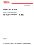
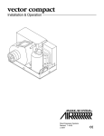
1
Document: GF07Z313 INSTALLATION & OPERATION MANUAL HV6CS Vacuum Circuit Breakers – Drawout Type 7.2kV Voltage Class APPLICABLE MODEL NUMBER: (Motor Operation Type) HV6CS-MLD (Drawout Cell) H6A-HLS Issued: December, 2012 Important Notice The instructions contained in this manual are not intended to cover all details or variations in equipment types nor may it provide for every possible contingency concerning the installation, operations, or maintenance of this equipment. Should additional information be required, contact your Toshiba Customer Support Center. The contents of this manual shall not become a part of or modify any prior or existing agreement, commitment, or relationship. The sales contract contains the entire obligation of Toshiba International Corporation. The warranty contained in the contract between the parties is the sole warranty of Toshiba International Corporation and any statements contained herein do not create new warranties or modify the existing warranty. Any electrical or mechanical modifications to this equipment without the prior written consent of Toshiba International Corporation may void all warranties or other safety certifications. Unauthorized modifications may also result in safety hazard or equipment damage. Misuse of this equipment could result in injury and equipment damage. In no event will Toshiba International Corporation be responsible or liable for direct, indirect, special, or consequential damage or injury that may result from the misuse of this equipment. About This Manual Every effort has been made to provide accurate and concise information to you, our customer. At Toshiba International Corporation we are continuously striving for better ways to meet the constantly changing needs of our customers. E-mail your comments, questions, or concerns about this publication to [email protected]. Purpose and Scope of Manual This manual provides information on how to safely install, operate, maintain, and dispose of your HV6CS breaker. The information provided in this manual is applicable to the HV6CS breaker only. This manual provides information on the various features and functions of this powerful device, including: • Installation • Operation • Mechanical and electrical specifications. Included is a section on general safety instructions that describe the warning labels and symbols that are used on the device and throughout the manual. Read the manual completely before installing, operating, performing maintenance, or disposing of this equipment. This manual and the accompanying drawings should be considered a permanent part of the equipment and should be readily available for reference and review. Dimensions shown in the manual are in imperial units and/or the metric equivalent. Connection drawings within this document convey the typical topology of the HV6CS breaker. Because of our commitment to continuous improvement, Toshiba International Corporation reserves the right, without prior notice, to update information, make product changes, or to discontinue any product or service identified in this publication. Toshiba International Corporation (TIC) shall not be liable for direct, indirect, special, or consequential damages resulting from the use of the information contained within this manual. This manual is copyrighted. No part of this manual may be photocopied or reproduced in any form without the prior written consent of Toshiba International Corporation. © Copyright 2012 Toshiba International Corporation. TOSHIBA® is a registered trademark of Toshiba Corporation. All other product or trade references appearing in this manual are registered trademarks of their respective owners. All rights reserved. Printed in the U.S.A. Contacting TIC’s Customer Support Center Toshiba International Corporation’s Customer Support Center can be contacted to obtain help in resolving any Adjustable Speed Drive system problem that you may experience or to provide application information. The Support Center is open from 8 a.m. to 5 p.m. (CST), Monday through Friday. The Center’s toll free number is US (800) 231-1412/Fax (713) 937-9349 CAN (800) 872-2192 MEX 01 (800) 527-1204. For after-hours support follow the directions of the outgoing message when calling. You may also contact Toshiba International Corporation by writing to: Toshiba International Corporation 13131 West Little York Road Houston, Texas 77041-9990 For further information on Toshiba International Corporation’s products and services, please visit our website at www.toshiba.com/ind/. TOSHIBA INTERNATIONAL CORPORATION HV6CS Circuit Breaker Complete the following information and retain for your records. Model Number: _____________________________________________________________________ Serial Number: _____________________________________________________________________ Project Number (if applicable):_________________________________________________________ Date of Installation: _________________________________________________________________ Inspected By: _____________________________________________________________________ Name of Application: ________________________________________________________________ Table of Contents General Safety Information ………………………………………………………………………. 1 Safety Alert Symbol ……………………………………………………………………….. 1 Signal Words ………………………………………………………………………………. 1 Equipment Warning Labels ………………………………………………………………. 2 Qualified Personnel ……………………………………………………………………….. 2 Equipment Inspection …………………………………………………………………….. 3 Handling and Storage …………………………………………………………………….. 3 Disposal ……………………………………………………………………………………. 4 During Use ………………………………………………………………………..……………….... 5 1. Part Names …………………………………………………………………………………….…. 8 2. From Receipt to Storage …………………………………………………………………….…. 9 2.1 Receipt and Unpacking ………………………………………………………………………… 9 2.2 Transport ……………………………………………………………………………………….... 10 2.3 Storage …………………………………………………………………………………………… 12 3. Installation ……………………………………………………………………….………………. 13 3.1 Mounting the Drawout Cell .….………………………………..…………………………..……13 3.2 Inserting the VCB into the Cell ………………………………………………….…………...…14 4. Operation …….…………………………………………………………………………………... 16 4.1 Manual Operation ……………………………………………………….……………………… 16 4.2 Electrical Operation …………………………………………………….…………………….... 19 4.3 Control Circuit .…….…………………………………………………….……………………... 20 5. Main Circuit Connections and Disconnecting/Removing the VCB …………………… 22 5.1 Connecting the Main Circuit ………..……….………………………………………………... 22 6. Maintenance/Inspections …..………………………………………………………………… 23 6.1 During Maintenance/Inspections …..……….………………………………………………... 24 6.2 Types of Maintenance and Inspection Work ……..…………………..…………………….. 24 6.3 Inspection Frequency …....……..……………………………………….………………….… 24 6.4 Periodic Inspection Checkpoints ……………………………….………..……………….….. 25 6.5 Vacuum Check …………………….…………………………….…………...…………….….. 26 -0- General Safety Information DO NOT attempt to install, operate, maintain, or dispose of this equipment until you have read and understood all of the product safety information and directions that are contained in this manual. Safety Alert Symbol The Safety Alert Symbol is comprised of an equilateral triangle enclosing an exclamation mark. This indicates that a potential personal injury hazard exists. Signal Words Listed below are the signal words that are used throughout this manual followed by their descriptions and associated symbols. When the words DANGER, WARNING, and CAUTION are used in this manual, they will be followed by important safety information that must be carefully followed. The word DANGER proceeded by the safety alert symbol indicates that an imminently hazardous situation exists that, if not avoided or if instructions are not followed precisely, will also occur. DANGER The word WARNING preceded by the safety alert symbol indicates that a potentially hazardous situation exists that, if not avoided or if instructions are not followed precisely, could result in serious injury to personnel or loss of life. WARNING The word CAUTION proceeded by the safety alert symbol indicates that a potentially hazardous situation exists that, if not avoided or if instructions are not followed precisely, may result in minor or moderate injury. CAUTION The word NOTE provides helpful information. NOTE -1- Equipment Warning Labels DO NOT attempt to install, operate, perform maintenance, or dispose of this equipment until you have read and understood all of the product labels and user directions that are contained in this manual. Warning labels that are attached to the equipment will include the exclamation mark within a triangle. DO NOT remove or cover any of these labels. If the labels are damaged or if additional labels are required, contact the Toshiba Customer Support Center. Labels attached to the equipment are there to provide useful information or to indicate an imminently hazardous situation that may result in serious injury, severe property and equipment damage, or loss of life if safe procedures or methods are not followed as outlined in this manual. Qualified Personnel Installation, operation, and maintenance shall be performed by Qualified Personnel ONLY. A Qualified Person is one that has the skills and knowledge relating to the construction, installation, operation, and maintenance of the electrical equipment and has received safety training on the hazards involved (Refer to the latest edition of NFPA 70E for additional safety requirements). Qualified Personnel shall: • Have carefully read the entire manual. • Be familiar with the construction and function of the ASD, the equipment being driven, and the hazards involved. • Be able to recognize and properly address hazards associated with the application of motor-driven equipment. • Be trained and authorized to safely energize, de-energize, ground, lock-out/tag-out circuits and equipment, and clear faults in accordance with established safety practices. • Be trained in the proper care and use of protective equipment such as safety shoes, rubber gloves, hard hats, safety glasses, face shields, flash clothing, etc., in accordance with established safety practices. For further information on workplace safety, visit www.osha.gov. -2- Equipment Inspection • Upon receipt of the equipment, inspect the packaging and equipment for shipping damage. • Carefully unpack the equipment and check for parts that may have been damaged during shipping, missing parts, or concealed damage. If any discrepancies are discovered, it should be noted with the carrier prior to accepting the shipment, if possible. File a claim with the carrier if necessary and immediately notify your Toshiba Customer Support Center. • DO NOT install the ASD if it is damaged or if it is missing any component(s). • Ensure that the rated capacity and the model number specified on the nameplate conform to the order specifications. • Modification of this equipment is dangerous and is to be performed by factory trained personnel ONLY. When modifications are required contact your Toshiba Customer Support Center. • Inspections may be required after moving the equipment. • Contact your Toshiba Customer Support Center to report discrepancies or for assistance if required. Handling and Storage • Use proper lifting techniques when moving the breaker; including properly sizing up the load, getting assistance, and using a forklift if required. • Store in a well-ventilated location and preferably in the original packaging if the equipment will not be used upon receipt. • Store in a cool, clean, and dry location. Avoid storage locations with extreme temperatures, rapid temperature changes, high humidity, moisture, dust, corrosive gases, or metal particles. • The storage temperature range of the breaker is 23° to 104° F (-5° to 40° C). • DO NOT store the unit in places that are exposed to outside weather conditions (e.g. wind, rain, snow, etc.). • Store in an upright position. -3- Operating the VCB Failure to take the opportunity to discover abnormalities can result in injuries and equipment damage. Always check to make sure that the ON and OFF indicators are correct before operating the equipment. To avoid damaging the equipment, do not close the circuit when the unit switching indicator is ON. Connecting and disconnecting the main circuit To avoid injury and damage to the equipment, do not remove the holding pin unless you are moving the VCB outside the panel. To prevent electric shock or other injury, follow the instructions given in the instruction manual when moving the equipment in or out of the panel. Disposal Never dispose of electrical components via incineration. Contact your state environmental agency for details on disposal of electrical components and packaging in your area. -4- During Use Installation location To prevent damage to the VCB or performance degradation, do not store or install it in the following locations: * Places whose ambient temperature is outside the range of -5C to 40C (23F to 104F). This may result in damage or performance degradation. * Places exceeding 1000 m (3300 ft) elevation. This may result in damage or performance degradation. * Places where excessive dust is produced. This may result in damage or performance degradation. * Places where corrosive gases are produced. This may result in fire, damage or performance degradation. * Places with very high or very low humidity. This may result in damage or performance degradation. * Places subject to extreme variations in temperature. This may cause condensation to form and result in damage or performance degradation. * Places subject to vibrations. This may result in damage or performance degradation. * Inclined locations. This may result in damage or performance degradation. -5- Special environmental conditions When using the VCB in special environments, check the points in Table 1 below. Table 1 Points to Check When Using the Circuit Breaker in Special Environments Special environmental condition Contamination Practical example Check points * Large amounts of dust. * Reduce the size of the ventilation duct * Salt corrosion (locations near the seashore or where winds containing salts blow) * Make sure the wind does not blow directly at the location where the ventilation duct is installed * Install a filter High humidity Corrosive gases * Places subject to frequent and/or strong rainstorms or snowstorms * Use a cubicle construction that will prevent condensation from forming * When there is a cooling tower or other large water source nearby * Use a cubicle construction that will prevent the wind from blowing directly into the cubicle * Where there is condensation (which forms when the humidity in the cubicle drops dramatically) * When corrosive gases are produced at plants handling raw materials, at water treatment plants, in hot springs regions etc. (hydrogen chloride, sulfurous acid, nitrogen oxide, ammonia, chlorine, ozone etc. or other gases) -6- * Install a space heater * Use a cubicle construction that enables the cubicle to be blocked off from the outside air to the greatest extent possible * Install a filter Applicable standards pertaining to switching surges Consult Table 2 for the standards applicable to VCB switching surges. Table 2 Applicable Standards Pertaining to Switching Surges Circuit breaker type Load type Rotating machine *1 Dry type transformer (insulation resistance below class A) Protected by surge suppressor Oil-immersed transformer (insulation resistance class A) When there is electronic equipment on transformer low voltage side Protected by CR suppressor *6 Phase advance capacitor *4, *5 6.6 kV circuit: No special restrictions up to 300 kVA No special No special Protected by CR 6.6 kV circuit: Low surge No special restrictions *3 restrictions suppressor *6 No special type restrictions *2 restrictions up to 4000 kVA *1. Mainly induction motors, but also includes synchronizing generators for private generator equipment. *2. Use a CR suppressor for surge protection when inching at 55 kW (75HP) or below and on inductance regulators. *3. Use an arrester for surge protection on circuits that require cutting off of excitation rush current. *4. When the capacity of the group of capacitors exceeds 300 kVA, insert a series reactor (6%). *5. For high-frequencies included in the applicable circuit, use 135% or below of the fifth harmonic as established in the standards for phase advance capacitors (JIS C 4801). *6. Table 3 shows the models of applicable CR suppressor. Ordinary Protected by CR suppressor *6 No special restrictions Table 3 CR Suppressors Circuit voltage 6.6 kV CR suppressor model NV60K304T1 (three-phase) -7- 1. Part Names SHAFT FOR MANUAL CHARGING HANDLE ON-OFF INDICATOR DRAWOUT CELL SPRING INDICATOR INTERLOCK LEVER CLOSE LEVER TRIP LEVER VCB COUNTER SECONDARY DISCONNECTS DRAWOUT HANDLES Figure 1 Drawout Type Circuit Breaker -8- 2. From Receipt to Storage 2.1 Receipt and Unpacking Each VCB unit is carefully tested and inspected prior to shipment, so it can be used as soon as it has been unpacked. However, just in case something should be amiss, you should check the following: (1) When the box is delivered, check to make sure it is not damaged or warped. (2) Remove the unit from the box carefully to avoid damaging it. CAUTION To prevent injury or damage to the equipment, make sure the unit is standing straight up. NEVER lay it on its side or place it upside-down. (3) Make sure the accessories (see Tables 4 & 5) are present and no parts are missing or damaged. WARNING To prevent electric shock or other injury, do not use the unit if it has been damaged. (4) Contact your dealer in the event of missing parts, damage, etc. Table 4 List of Accessories (VCB) Part Appearance Quantity 1 B9 grease Handle (with mounting screw) shipped together with the VCB unit. 1 -9- Table 5 List of Accessories (Drawout Cell) Part Appearance Quantity Control cable (2m) 1* 2.2 Transport CAUTION Use the proper procedures when moving or transporting the unit. Failure to use the proper (authorized) methods may damage the unit or cause it to fall, resulting in injury. 2.2.1 Transporting U Type VCBs (main circuit terminals on top left and right) Cable Figure 2 Hoisting the Circuit Breaker - 10 - 2.2.2 Drawout Cell When hoisting the drawout unit, attach cable (wire rope) to the holes on the left and right of the rear of the unit, as shown in Figure 3. Cable Figure 3 Lifting the Drawout Cell - 11 - 2.3 Storage Use the following procedures if the VCB will not be operated for a long period of time after it has been installed, or if it must be stored for a long period of time prior to installation. Be sure to observe the precautions for storage and installation locations (see page 5). (1) When storing the unit, cover it with a dust cover. (2) Avoid locations subject to high humidity or exposed to direct sunlight. (3) Inspect the unit periodically and make sure there are no problems such as condensation, moisture absorption, rust, corrosion or insects inside the equipment. If such problems are discovered, inspect the equipment carefully and repair it before it is operated. WARNING To prevent electric shock or other injury, do not use the unit when a problem has been discovered during an inspection of that unit. CAUTION To prevent injury or damage to the equipment, make sure the unit is standing straight up. NEVER lay it on its side or place it upside-down. (4) When the equipment has been stored or has been idle for a long period of time, do not install or begin operating the unit immediately. Perform the procedures listed in sections 7.3 and 7.4 and the withstand voltage test* for the control circuit to make sure there are no problems before installing or operating the unit. *The withstand voltage on control circuits The withstand voltage test for motor spring operation type circuit breaker shall be performed in charged condition. The power frequency withstand voltage on control circuits except charging motor is 2000V AC, since the withstand voltage for charging motor is 1500V AC. The motor circuit shall be disconnected before withstand voltage test on control circuits. (Example: The connector plug (white) on upper-center of control board should be disconnected (pull out) after removing the front cover of circuit breaker. This will make the motor circuit disconnect Note: The connector plug and front cover must be returned to proper position after withstand voltage test. CONNECTOR PLUG (WHITE) CONTROL BOARD (UNIT) - 12 - 3. Installation Make sure the location satisfied the requirements listed under Storage and Installation Location (page 3) and check the dimensions using the diagrams in other catalogs or external view diagrams and panel cut diagram. Prior to installation, the maximum fault current capacity of the power system at the point of installation should be verified. This value must not exceed the symmetrical interrupting capability of the circuit breaker. See typical circuit breaker nameplate below. DANGER Do not exceed the ratings specified on the breaker nameplate or system accessories. Underrated equipment can fail during operation causing fire, explosion, severe injury, death, and property damage. Typical Circuit Breaker Nameplate 3.1 Mounting the Drawout Cell 3.1.1 Mounting in the panel To install the draw-out unit, perform the steps shown in Figures 4 and 5 in that order. Figure 4 Fasten the drawout cell to the panel with the 4 hexagonal bolts (M8). Tightening torque should be 11.8 to 14.7 N-m (120 to 150 kgf-cm). - 13 - Figure 5 Crimp the crimp-on terminal provided with the unit to the grounding wire and use the hexagonal bolt (M8) to fasten it in place. The tightening torque should be 11.8 to 14.7 N-m (120 to 150 kgf -cm). Screw nominal dia. M4 M5 M6 Tightening torque 1.47 to 1.96 N-m (15 to 20 kgf-cm) 2.94 to 3.92 N-m (30 to 40 kgf-cm) 4.90 to 6.37 N-m (50 to 65 kgf-cm) Screw Nominal dia. M8 M10 M12 Tightening torque 11.8 to 14.7 N-m (120 to 150 kgf-cm) M10 24.5 to 30.9 N-m (250 to 315 kgf-cm) 44.1 to 55.4 N-m (450 to 565 kgf-cm) Table 5 Tightening Torque 3.2 Inserting the VCB into the Cell (Outside the cell →disconnected position) Perform the steps shown in Figures 6 through 10 in that order. . Figure 6 Open the B9 grease provided with the unit and apply it to the ends of the six contacts. Figure 8 Align the hole on the lifter with the lifter pin on the cubicle and remove the VCB holding pin on the draw-out unit side. - 14 - Figure 7 Place the VCB on the lifter. Figure 9 Hold the handle with both hands and, with the interlock lever in the raised position, insert the VCB into the panel. Location of VCB holding pin (with chain) Figure 10 Align the positioning arrow on the VCB with the disconnect position and release the interlock lever. Check to make sure the interlock lever has returned to its former position. Insert the VCB holding pin. - 15 - 4. Operation CAUTION Failure to take the opportunity to discover abnormalities can result in injuries and equipment damage. Always check to make sure that the ON and OFF indicators are correct before operating the equipment. 4.1 Manual Operation CAUTION To avoid damaging the equipment, do not close the circuit when the unit switching indicator is ON. 4.1.1 Closing the Circuit Check to make sure that the switching status is set to OFF. 4.1.1.1 For Motorized Spring-operated VCBs Attach the handle using the steps shown in Figures 11 and 12, in that order. The manual charging handle shall be applied for emergency case and maintenance purpose only, remove (not install) the handle at normal service condition. Figure 11 Attach the handle provided with the unit to the handle shaft. Check to make sure that the handle has been securely connected to the shaft (small screw M5). - 16 - Figure 12 Using the small screw (M5) provided, fasten the handle in position. The tightening torque should be 2.94 to 3.92 N-m (30 to 40 kgf-cm). (1) When the spring is released Perform the steps shown in Figures 13 and 14 in that order. CHARGING HANDLE CLOSED LEVER Figure 13 Turn the handle clockwise 3 to 5 times and make sure that the spring status is taut. Figure 14 Press the closed lever (green) in the direction of the arrow to close the circuit. When the switching status will change to ON, the VCB is set in close state. (2) When the spring is taut Perform the step shown in Figure 15. CLOSED LEVER Figure 15 Press the closed lever (green) in the direction of the arrow to close the circuit. When the switching status will change to ON, the VCB is set in close state. - 17 - 4.1.2 Opening the Circuit This operation is the same for both motorized and manual spring-operated VCBs. TRIP LEVER Figure 16 Press the trip lever (red) in the direction of the arrow to open the circuit. - 18 - 4.2 Electrical Operation Electrical operations are performed as shown in the flow diagram below. Circuit breaker OPEN Control power applied Motor begins operating ・Springs begin tightening ・Spring status changes to yellow ・CLOSE operation standby Springs Charged・Motor stops CLOSE signal given CLOSE coil energized Spring changes to white and switching status changes to ON Circuit breaker CLOSED Auxiliary relay closes Motor begins operating ・Spring begins tightening Anti-pumping circuit completed Spring taut・Motor stops OPEN signal given Spring status changes to yellow OPEN/TRIP coil energized Circuit breaker OPEN Switching status changes to OFF Next CLOSE operation is NOT possible until the CLOSE signal is canceled. - 19 - 4.3 Control Circuit 4.3.1 Motorized Operation Figure 17 Control Circuit - 20 - 4.3.2 Undervoltage Trip All HV6CS breakers are furnished with an undervoltage trip device. The Undervoltage trip device operates to trip the circuit breaker OFF unless 120VAC control power is present at the terminals of the UV (TC4) trip coil. When the circuit breakers are shipped, the Undervoltage trip device is defeated by a factory installed plug (Figure 18). If this plug is left in place, the circuit breaker will operate normally without power applied to the UV coil. Removing this plug (Figure 19) activates the undervoltage trip function. Figure 18 Plug Installed in UV Trip Device Figure 19 Remove Plug From UV Trip Device - 21 - 5. Main Circuit Connections and Disconnecting/Removing the Circuit Breaker from the Cell 5.1 Connecting the Main Circuit (disconnected position to connected position) Perform the steps shown in Figures 20 through 21 in that order. WARNING To avoid damaging the equipment, do not connect or disconnect the main circuit when the unit switching status is ON. To prevent electric shock or other injury, do not bend or modify the in/out interlock attached the unit. CAUTION To avoid injury and damage to the equipment, do not remove the holding pin unless you are moving the VCB outside the panel. To prevent electric shock or other injury, follow the instructions given in the instruction manual when moving the equipment in or out of the panel. Figure 20 Insert the control circuit connector into the port on the VCB. Figure 21 Grasp the handle with both hands and, with the interlock lever in the raised position, insert the VCB up to the connected position. * The interlock lever cannot be raised when the switching status of the VCB is set to ON. Perform the open circuit operation and set the switching status to OFF. - 22 - 6. Maintenance/Inspections To prevent electric shock, turn off the power before starting maintenance and inspections. To prevent electric shock or other injury, check to make sure that the unit status indicators read OFF and DISCHARGED before beginning maintenance and inspection work. To prevent electric shock, do not touch charged parts. WARNING Keep fingers and other body parts, objects, etc. away from the unit mechanism, as you may become caught in the mechanism and injured. To prevent electric shock or other injury, do not attempt to modify the lock mechanism on the disconnecting switch mounted on the unit power side. Hazardous voltage can cause serious injury or death. Make sure maintenance and inspection work is performed only by authorized personnel. The VCB should be maintained and inspected periodically to maintain performance and ensure a long service life. Operating and environmental conditions will usually dictate the frequency of inspection required. NFPA Publication 70B "Electrical Equipment Maintenance" may be used as a guide for setting up the maintenance program. DANGER Contact with energized components can cause severe injury, death and property damage. Turn off and lock-out primary and control circuit power before servicing. Improper maintenance can cause severe injury, death and property damage. WARNING Only qualified and authorized persons are to install, operate or service this equipment. Grease is conductive. Do not allow grease or any other substances to WARNING contaminate insulating materials. Contaminated insulators can allow a short circuit or ground fault to occur. MAINTENANCE RECORD Keep a permanent record of all maintenance work. At a minimum, this record should include: 1) Items inspected 2) Reports of any testing 3) Equipment condition - 23 - 4) Corrective actions or adjustments 5) Date of work 6.1 During Maintenance/Inspections Before inspecting the electrical circuits, take the following measures to prevent electric shock: 1) After opening circuit for the VCB, open the disconnect switch on the power source side to place the main circuit and control circuits of the VCB in no-voltage status. 2) Lock the disconnect switch to prevent operation and label it with an "INSPECTION IN PROGRESS" tag. 3) Using a voltage detector, check to make sure that the circuits are in no-voltage status and ground the necessary circuits. Discharge the residual charge from capacitors and cables before grounding. Space heaters, resistors and other units will remain hot even after they have been turned off. Install a protective cover temporarily, or wait until after the units have cooled to perform the inspection. To ensure safety, remove the ground line after the inspection is complete and return the equipment to its previous status. 6.2 Types of Maintenance and Inspection Work Receiving inspection A visual inspection for damage, deformation, missing parts and switching status (manual) to make sure that the product is in the same status as when it was shipped. Patrol inspection An inspection performed during patrols to check for abnormal noise or odor and see if there is anything wrong with the equipment during operation. Periodic inspection The equipment is shut off and a check made of the operation of the mechanism to make sure there is nothing wrong. The lubrication status of sliding and rotating parts is also checked and the mechanism is lubricated if needed. Unscheduled inspection Inspections that are implemented as required. 6.3 Inspection Frequency The inspection frequency and points to be inspected will differ depending on the status of use, frequency of switching, the size of the breaking current and other factors. In general, inspections should be implemented at the intervals shown in the table below. - 24 - Table 7 Inspection Frequency Inspection frequency Once every 6 months Normal Once every 1 to 3 years or every 3,000 operations Detailed Once every 6 years Unscheduled Inspection As needed Type of inspection Patrol Inspection Periodic Inspection 6.4 Periodic Inspection Checkpoints No. Location 1 Operating mechanism 2 Main circuit Table 8 Periodic Inspection Checkpoints Item Inspection Criteria method Loose bolts, Tighten using Make sure all nuts or screws screwdriver or bolts, nuts and wrench. screws are tight. Dust or foreign matter inside Visual inspection. Indicator operation Visual inspection. Part warping Visual inspection. Smooth action Manual operation. Visual inspection or touch. See Lubrication Manual Visual inspection. Discoloration due to heat from conducting parts Make sure there is no dust or foreign matter. Make sure switching status is properly displayed. Make sure no parts are warped or missing. Make sure action is smooth and shafts turn smoothly. Disposition Remarks Tighten if loose. See Table 6 for tightening torque. Wipe with a dry cloth. Check the cause and repair. Check the cause and repair. If action is not smooth, apply a small amount of lubricant. Make sure there is no discoloration. Check the cause and repair. Loose bolts, nuts or screws Tighten using a wrench. Make sure all bolts, nuts and screws are tight. Tighten if loose. Dust on surface of interrupter Visual inspection. Make sure there is no surface dust. Wipe with a clean dry cloth. - 25 - See Table 6 for tightening torque. No. Location Item 3 Insulator Dust, foreign matter or damage 4 Auxiliary switch Terminals loose or disconnected Case/contacts 5 6 Control circuits Insulation resistance measurement Smooth movement when electricity is supplied Terminals loose or disconnected Inspection method Visual inspection. Visual inspection. Tighten using a screwdriver. Visual inspection Supply electricity to operate the circuit. Visual inspection Tighten using a screwdriver. Measurement point Main conductor to ground Group of control circuits to ground Between main circuit terminals Insulation resistance 500M or greater Criteria Disposition Remarks Make sure there is no dust, foreign matter or breakage. Make sure terminals are not loose or disconnected. Make sure there is no damage or Warping. Make sure circuit operates smoothly. Wipe with a clean dry cloth. If damaged, contact Toshiba. Repair if disconnected. Tighten if loose. Replace if damaged or warped. If circuit fails to operate, check the cause and repair. See Table 6 for tightening torque. Make sure terminals are not loose or disconnected. Repair if disconnected. Tighten if loose. If the insulation resistance between the main circuit terminals is low, wipe the vacuum valve and insulator surface with a clean dry cloth and repeat the test. See Table 6 for tightening torques. Tester 1000 V 2M or greater 500 V 100M or greater 1000 V 6.5 Vacuum Check A sufficient level of vacuum is necessary for proper performance of the vacuum interrupters. Although vacuum leaks are rare, the vacuum integrity should be checked periodically. The relationship between dielectric breakdown voltage of the contact gap and internal vacuum interrupter pressure has been found to be generally predictable. Therefore, vacuum interrupter integrity is checked by performing a high potential test across the open gap of the interrupter. TEST EQUIPMENT: - 26 - Toshiba offers a compact vacuum checker (Type CI35-1D, see Figure 22) which enables a quick and easy check on vacuum interrupter internal pressure. Alternatively, any commercially available AC high potential tester may be used which is capable of delivering at least 25 milliamperes at 22 kV for a period of one minute. Figure 22 Toshiba Portable Vacuum Checker PRECAUTIONS: Applying abnormally high voltage across a pair of contacts in vacuum may produce X-rays. The radiation may increase with the increase in voltage and/or decrease in contact spacing. X-radiation produced during this test with recommended voltage and normal contact spacing is extremely low and well below the maximum permitted by standards. As an additional safety measure, it is recommended that all personnel keep at least 1 meter (3.3 ft) away from the vacuum circuit breaker while this test is performed. WARNING Radiation exposure hazard. X-rays may cause illness or injury. Stay at least 1 meter (3.3 ft) away from the circuit breaker during the vacuum check test . WARNING Hazardous voltages are present during dielectric testing which can result in severe injury or death. Only qualified personnel should conduct this testing. See Figure 23 for sample withstand voltage test circuit. Figure 23 Sample Withstand Voltage Test Circuit - 27 - TEST PROCEDURE: 1. The circuit breaker should be disconnected from the main circuit and be in the OFF position. 2. Connect all the line side primary terminals together and to the output of the vacuum checker or AC hi-pot machine. Connect all the load side primary terminals together and to the ground terminal of the vacuum checker or AC hi-pot machine. 3. Increase the voltage from zero to 22kV AC at a rate of approximately 2kV per second. Hold the voltage at this value for 1 minute and observe the current drawn by the interrupter. Note: If the ammeter fluctuates violently as the voltage increases to AC22 kV, repeat the voltage increase procedure two or three times. If the current still rises when the voltage is increased, the vacuum level may be insufficient; replace the vacuum interrupter. 1 minute 22kV AC 4. Decrease the voltage back to zero. (31kV DC) CRITERIA: 1. If a current flow above 5 milliamperes is observed or if breakdown occurs, one or more of the interrupters has insufficient vacuum and must be replaced. Exception: If the current exceeds 5 milliamperes the first time the voltage is brought up, reduce the voltage to zero and increase it again. It may be necessary to repeat this procedure a few times. 2. If the breaker fails to meet criteria 1, then repeat the test on each pole separately to identify the damaged interrupter or interrupters. Voltage Zero 15 sec 15 sec Time Figure 24 Application of Test Voltage for Vacuum Check 3. If the voltage can be held for 1 minute and the current flow does not exceed 5 milliamperes, the interrupter has a sufficient vacuum level. After the test is complete, discharge any residual static charge from the primary terminals of the circuit breaker. If a vacuum checker or AC hi-pot tester is not available, a DC hi potential test may be conducted. If a DC test is conducted, the test voltage must be increased to 31kV DC. The test duration for DC tests and the criteria for acceptance remain the same as for AC tests. WARNING Do not use DC hi-pot testers which employ unfiltered half-wave rectifiers. The peak voltages produced by these testers may exceed the recommended value of 31kV. This can result in the production of harmful X-rays and may invalidate the test results. - 28 - Figure 25 shows the relationship between the dielectric breakdown characteristics and the withstand voltage between electrodes (for each vacuum interrupter) in the withstand voltage test. Figure 25 Dielectric Breakdown Characteristics - 29 - - 30 - - 31 - TOSHIBA TOSHIBA INTERNATIONAL CORPORATION INDUSTRIAL DIVISION 13131 W. Little York Road, Houston, TX 77041 U.S.A. Tel: +713- 466-0277 US 1-800- 231-1412 Fax: (713) 466-8773 www.toshiba.com/ind