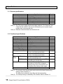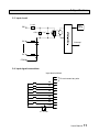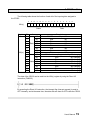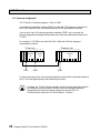
1
UM-TS03∗∗∗-E024
PROGRAMMABLE CONTROLLER
PROSEC T3
CHANGE DETECT DC INPUT MODULE
CD332
USER’S MANUAL
TOSHIBA CORPORATION
Important Information
Misuse of this equipment can result in property damage or human injury.
Because controlled system applications vary widely, you should satisfy yourself
as to the acceptability of this equipment for your intended purpose.
In no event will Toshiba Corporation be responsible or liable for either indirect
or consequential damage or injury that may result from the use of this equipment.
No patent liability is assumed by Toshiba Corporation with respect to use of
information, illustrations, circuits, equipment or examples of application in this
publication.
Toshiba Corporation reserves the right to make changes and improvements to this
publication and/or related products at any time without notice. No obligation shall be
incurred other than as noted in this publication.
This publication is copyrighted and contains proprietary material. No part of this book
may be reproduced, stored in a retrieval system, or transmitted, in any form or by any
means ⎯ electrical, mechanical, photocopying, recording, or otherwise ⎯ without
obtaining prior written permission from Toshiba Corporation.
© TOSHIBA Corporation 1996. All rights reserved
Publication number: UM-TS03∗∗∗-E024
1st edition August 1996
PROSEC is a registered trademark of TOSHIBA Corporation.
Safety Precautions
This module (CD332) is a change detect DC input module for Toshiba’s Programmable Controller
PROSEC-T3 or T3H (hereafter called T3 generically). Read this manual thoroughly before using
this module. Also, keep this manual and related manuals so that you can read them anytime while
this module is in operation.
Safety Symbols
The following safety symbols are used on the product and/or in the related manuals.
Pay attention to information preceded by the following symbols for safety.
! WARNING
Indicates a potentially hazardous situation which, if not avoided,
could result in death or serious injury.
! CAUTION
Indicates a potentially hazardous situation which, if not avoided,
may result in minor or moderate injury. It may also be used to alert
against unsafe practices.
Safety Precautions
! CAUTION
• Turn off power to the T3 and to the CD332 before removing or mounting the CD332.
Failure to do so can cause electrical shock or damage to this product.
• Read the Safety Precautions described in the T3 User’s Manual before using the T3
and the CD332.
• Follow the instructions described in this manual and in the T3 User’s Manual when
installing and wiring the T3 and the CD332.
• The CD332 has been designed for the T3. Use your CD332 only on the rack of the T3.
• Remove the CD332 from the rack before setting the jumper plugs on the CD332.
Do not touch other components on the CD332’s printed circuit board. It may cause
damage to the CD332.
• The CD332 consumes maximum 0.3 A of internal 5 Vdc power. Confirm that the total
5 Vdc consumed current per one power supply module is within the limit (7A).
If it exceeds the limit, the T3 cannot operate properly and this may cause unsafe
situation.
User’s Manual
1
About This Manual
About This Manual
This manual explains the specifications and operations of the Change Detect DC Input
Module (CD332) for Programmable Controller T3. Read this manual carefully before using
the CD332.
Inside This Manual
Section 1 Overview
This section introduces the CD332. The CD332 has an interrupt generation function for the
T3. This section outlines the CD332’s function. The external features of the CD332 are also
provided in this section.
Section 2 Specifications
This section provides the hardware and functional specifications of the CD332. The
information for external wire connections is also provided in this section.
Section 3 Mode Setting
The input delay time and the interrupt generation timings are user selectable. This section
explains the switch settings for this purpose.
Section 4 I/O Allocation
This section provides the information to design T3 program for the CD332. This section
explains the I/O allocation and functions of the I/O register assigned to the CD332.
Section 5 Programming
The CD332 generates an interrupt signal for the T3. This section provides T3’s sample
program for the CD332. Precautions for using the interrupt function are also explained in
this section.
2
Change Detect DC Input Module (CD332)
About This Manual
Related Manuals
The following related manuals are available for T3. Besides this manual, read the following
manuals for your better understanding.
T3 User’s Manual - Hardware
This manual covers the T3’s main body and basic I/O - their specifications, handling,
maintenance and services.
T3 User’s Manual - Functions
This manual explains the functions of the T3 and how to use them. The necessary
information to create user program is covered in this manual.
T3H User’s Manual
This manual explains the specifications of the T3H and the functional differences between
the T3H and the T3.
T-series Instruction Set
This manual provides the detailed specifications of instructions for Toshiba’s T-series
Programmable Controllers.
T-series Computer Link Function
This manual provides the information for a computer to communicate with T3 through the
T-series Programmable Controller’s Computer Link function.
T-PDS (Ver. 1.4) Basic Operation manual
This manual explains how to install the T-series program development system (T-PDS)
into your computer and provides basic programming operations.
T-PDS (Ver. 1.4) Command Reference Manual
This manual explains the T-series program development system (T-PDS) in detail.
T-PDS (Ver. 1.6) Expanded Functions
This manual explains the expanded functions on the T-PDS version 1.6. This manual
supplements the T-PDS (Ver.1.4) Command Reference Manual.
T-series Handy Programmer (HP911) Operation Manual
This manual explains the functions and key operations of the T-series Handy Programmer
(HP911).
NOTE
Other than the listed above, some T3 related manuals for special I/O modules and data
transmission modules are available. Contact Toshiba for more information.
User’s Manual
3
Contents
Contents
Safety Precautions
......................................................................................
1
About This Manual
......................................................................................
2
.....................................................................................................
4
Contents
4
1.
CD332 Overview
.............................................................................
5
1.1
1.2
Introduction
......................................................................................
External features
..............................................................................
6
7
2.
Specifications
................................................................................
9
2.1
2.2
2.3
2.4
General specifications
....................................................................
Functional specifications
.................................................................
Input circuit
....................................................................................
Input signal connections
.................................................................
10
10
11
11
3.
Mode Setting
.................................................................................
13
3.1
3.2
Input delay setting
...........................................................................
Interrupt generation timing setting
...................................................
14
15
4.
I/O Allocation
.................................................................................
17
4.1
4.2
I/O allocation and I/O register
.........................................................
Interrupt assignment
.......................................................................
18
20
5.
Programming
................................................................................
21
5.1
5.2
T3 sample program
Interrupt operation
.........................................................................
..........................................................................
22
24
Change Detect DC Input Module (CD332)
Section 1
CD332 Overview
1.1 Introduction, 6
1.2 External features, 7
User’s Manual
5
1. CD332 Overview
1.1 Introduction
The change detect DC input module CD332 (hereafter called CD332) is an 8 points 12
- 24 Vdc input module with interrupt generation function for Toshiba’s Programmable
Controller PROSEC-T3 or T3H (hereafter called T3 generically).
When the input signal status of the CD332 is changed, the CD332 generates an
interrupt for the T3. Then the T3 immediately stops ordinary operation and starts to
execute the pre-assigned I/O interrupt program.
The task switching time in the T3 is less than 500 µs. (under interrupt enable state)
The interrupt generation timing of the CD332 can be selected as follows for each input
point. This selection is made by the DIP switches provided on the front of the CD332.
(1) Rising edge (from OFF to ON)
(2) Falling edge (from ON to OFF)
(3) Both edges (both OFF to ON and ON to OFF)
This CD332 has 8 input points. By using one CD332, up to 8 interrupt factors can be
processed. On the other hand, up to 8 I/O interrupt programs are available in the T3.
Therefore, total up to 64 (= 8 × 8) interrupt factors can be processed by the T3 by using
8 CD332s.
The input voltage of the CD332 is 12 to 24 Vdc. The input delay time can be selected
either normal or high speed as 8 points block by setting the internal jumper plugs.
NOTE
6
The T3 supports 8 I/O interrupt programs. Therefore, maximum 8 CD332s
can be used with the T3.
Change Detect DC Input Module (CD332)
1. CD332 Overview
1.2 External features
CD332
DATA
0 1 2 3 4 5 6 7
Status LEDs
STATUS
0 1 2 3 4 5 6 7
CHANGE DETECT
UP
IN0
1
2
3
4
5
6
7
ON
Interrupt timing setting DIP switches
DOWN
IN0
1
2
3
4
5
6
7
ON
NC
NC
IN0
IN1
IN2
IN3
IN4
IN5
IN6
IN7
COM
1
2
3
4
5
Input terminals
6
7
8
9
10
11
NOTE
Do not connect any wires to
the NC terminals.
CD332
User’s Manual
7
1. CD332 Overview
Status LEDs
Indicates the input signal ON/OFF status (DATA 0 - 7) and the interrupt generation
point (STATUS 0 - 7). Normally STATUS 0 - 7 are all OFF. (momentary ON)
DATA 0 - 7
STATUS 0 - 7
Indicates the input signal status of IN0 to IN7. Lit when ON.
Indicates the input point which is the interrupt factor.
(returned to OFF by resetting the interrupt flag)
Interrupt timing setting DIP switches
Total 16 switches are provided. These switches are used to set the interrupt
generation timing for each input point. (Rising, falling or both edges)
Refer to section 3.2.
Input terminals
Used to connect the external input signals. Refer to section 2.4.
NOTE
Do not connect any wires to the NC terminals.
Jumper plugs
CD332 rear view
Jumper plugs for selecting the input delay are
provided. Refer to section 3.1.
8
Change Detect DC Input Module (CD332)
Section 2
Specifications
2.1
2.2
2.3
2.4
General specifications, 10
Functional specifications, 10
Input circuit, 11
Input signal connections, 11
User’s Manual
9
2. Specifications
2.1 General specifications
Item
Power voltage
Current consumption
Environmental conditions
Withstand voltage
Size
Weight
Specifications
5 Vdc (supplied from back plane bus)
0.3 A (5 Vdc) maximum
Conforms to T3 specifications
1500 Vac - 1 minute
T3 I/O module size (1 slot)
Approx. 450 g
Remarks
Note (1)
Note (2)
Note (1) The T3’s power supply module can supply maximum 7 A of internal 5 Vdc.
Check that the internal 5 Vdc current consumption per one power supply
module does not exceed the limit.
Note (2) Between external terminals and internal circuit.
2.2 Functional specifications
Item
Module type
I/O allocation type
Input type
Number of input points
Rated input voltage
Input voltage range
Rated input current
Minimum ON voltage
Maximum OFF voltage
ON delay time
OFF delay time
LED
display
DATA 0 - 7
STATUS 0 - 7
Interrupt function
Number of modules on T3
Specifications
Change detect DC input
iX 1W
DC input, current source/sink
8 points (8 points/common)
12 - 24 Vdc
10 - 30 Vdc
10 mA (at 24 Vdc)
9.6 Vdc
3.5 Vdc
30 ms or less (normal mode)
3.0 ms or less (high speed mode)
35 ms or less (normal mode)
3.5 ms or less (high speed mode)
Input status display for all points,
lit at ON, internal logic side
Interrupt point display, returned to OFF
by resetting the interrupt flag
Generates interrupt signal for T3 when
input status of each point is changed.
Interrupt timing can be selected for each
point either rising, falling or both edges.
Max. 8 modules
Remarks
Note (1)
Note (1)
Note (2)
Note (1) The normal or high speed mode can be selected by internal jumper plug
settings. Refer to section 3.1.
The delay time includes the input filter and internal sampling.
Note (2) The interrupt timing is selected by DIP switches. Refer to section 3.2.
10
Change Detect DC Input Module (CD332)
2. Specifications
2.3 Input circuit
2.4 kΩ
LED
display
IN0
470 Ω
1.5 µF
IN1
Interrupt
IN7
COM
2.4 Input signal connections
Input terminal block
1
2
IN0
IN1
IN2
3
4
5
IN3
6
IN4
7
IN5
8
IN6
9
IN7
10
COM
Do not connect any wire
11
12 - 24 Vdc
User’s Manual
11
12
Change Detect DC Input Module (CD332)
Section 3
Mode Setting
3.1 Input delay setting, 14
3.2 Interrupt generation timing setting, 15
User’s Manual
13
3. Mode Setting
3.1 Input delay setting
The input delay time of the CD332 can be selected either normal or high speed mode.
Refer to section 2.2 for the delay time of each mode.
The input delay setting is made by the jumper plugs provided on the CD332’s printed
circuit board. This setting is applied for all 8 input points as a block.
CD332 left side
J9
A
B
A
J10
B
J11
J1
J2
J3
J4
J5
J6
J7
J8
Set these jumper plugs as follows.
Mode
Normal mode
High speed mode
NOTE
14
J1
J2
J3
J4
J5
J6
ON (short)
OFF (open)
J7
(1) The factory setting is the normal mode.
(2) Use a pair of tweezers to set the jumper plugs.
(3) J9 must be always OFF (open).
Change Detect DC Input Module (CD332)
J8
J9 J10 J11
OFF B side
OFF A side
3. Mode Setting
3.2 Interrupt generation timing setting
The interrupt generation timing of each input point can be selected either rising, falling
or both edges.
• Rising edge (OFF to ON)
Input
OFF
ON
OFF
ON
OFF
Interrupt
• Falling edge (ON to OFF)
Input
OFF
Interrupt
• Both edges (OFF to ON and ON to OFF)
Input
OFF
ON
OFF
Interrupt
This setting is made by the DIP switches provided on the front of the CD332.
CHANGE DETECT
Mode
Rising edge
Falling edge
Both edges
UP
IN0
1
2
3
4
5
6
7
ON
DOWN
IN0
1
2
3
4
5
6
7
NOTE
UP
ON
OFF
ON
DOWN
OFF
ON
ON
(1) This setting is available for each input
point individually.
(2) The factory setting is all ON.
(Both edges)
(3) Changes of the DIP switches are
effective while power on.
ON
User’s Manual
15
16
Change Detect DC Input Module (CD332)
Section 4
I/O Allocation
4.1 I/O allocation and I/O register, 18
4.2 Interrupt assignment, 20
User’s Manual
17
4. I/O Allocation
4.1 I/O allocation and I/O register
The CD332 has the I/O type ‘i X 1W’ for I/O allocation. When the automatic I/O
allocation is performed with mounting the CD332, the following I/O allocation table will
be created in the T3.
(T-PDS screen example - in the case that CD332 is mounted on Slot 0 of Unit 0)
Then, one input register, XW(n) is assigned to the CD332.
In the above example, XW000 is assigned.
Note that the I/O type has ‘i’ designation. It means that the CD332 has interrupt
generation function for the T3, also the T3 will not update the assigned input register in
the batch I/O processing. To read data through the input register, the Direct I/O
instruction (FUN235) is necessary.
18
Change Detect DC Input Module (CD332)
4. I/O Allocation
The following table shows the function of each bit of the input register assigned to
the CD332.
F
E
D
C
B
A
9
8
7
6
5
4
3
2
1
0
XW(n)
Status
Register
XW(n)
Data
Bit
Name
Description
0
IN0 Indicates ON/OFF status of input IN0
1
IN1
Ditto
IN1
2
IN2
Ditto
IN2
3
Data IN3
Ditto
IN3
4
IN4
Ditto
IN4
5
IN5
Ditto
IN5
6
IN6
Ditto
IN6
7
IN7
Ditto
IN7
8
IN0 Comes ON when interrupt is generated by
9
IN1
Ditto
A
IN2
Ditto
B Status IN3
Ditto
C
IN4
Ditto
D
IN5
Ditto
E
IN6
Ditto
F
IN7
Ditto
IN0 changing
IN1 changing
IN2 changing
IN3 changing
IN4 changing
IN5 changing
IN6 changing
IN7 changing
The data of the CD332 can be read into the XW(n) register by using the Direct I/O
instruction (FUN235).
By executing the Direct I/O instruction, the interrupt flag (interrupt request) is reset to
OFF internally, and at the same time, the status bits are reset to OFF inside the CD332.
User’s Manual
19
4. I/O Allocation
4.2 Interrupt assignment
The T3 has 8 I/O interrupt programs, I/O#1 to I/O#8.
If one interrupt generation module (CD332) is used, the I/O#1 program is assigned to
the CD332. And the I/O#1 is activated when the CD332 generates an interrupt.
If two or more (up to 8) interrupt generation modules (CD332, etc.) are used, the
interrupt programs are assigned sequentially from the module allocated closest to the
T3 CPU.
For example, if 3 CD332s are used, the I/O#1, I/O#2 and I/O#3 are assigned
sequentially as follows.
T3 basic unit
0 1 2 3 4 5 6 7 8 9
P I C C
C
S F P D
D
U 3 General 3 General
I/O
I/O
3
3
2
2
I/O#1
I/O#2
Expansion unit
0 1 2 3 4 5 6 7 8 9 10
P I C
S F D
3
3
2
General
I/O
I/O#3
As for the interrupt priority, the interrupt generation module which is allocated closest to
the T3 CPU has highest priority and followed by this order.
NOTE
20
In default, the T3’s I/O interrupt program and the interrupt generation module
are related as mentioned above. However user can change this relation
(assignment) by using the interrupt assignment function of the T3.
For this function, refer to the T3 User’s Manual - Function.
Change Detect DC Input Module (CD332)
Section 5
Programming
5.1 T3 sample program, 22
5.2 Interrupt operation, 24
User’s Manual
21
5. Programming
5.1 T3 sample program
The following sample program configuration shows the case of one CD332 is used.
In this example, it is assumed that XW000 is assigned to the CD332.
Main Program
c
User program
(Main program)
d
I/O Interrupt Program #1 (I/O#1)
e
Processing for IN0 interrupt
Processing for IN1 interrupt
Processing for IN2 interrupt
Processing for IN3 interrupt
f
Processing for IN4 interrupt
Processing for IN5 interrupt
Processing for IN6 interrupt
Processing for IN7 interrupt
g
22
Change Detect DC Input Module (CD332)
5. Programming
c At the first scan, initializes the status of the CD332. − Important
d End of the main program
e Resets the interrupt flag and confirms the interrupt factor. − Important
f Processing program for each interrupt factor
(Subroutine call can also be used)
g End of the interrupt program
NOTE
When the Direct I/O instruction for the CD332 is executed, the internal
interrupt flag of the CD332 is reset. Therefore, do not use the Direct I/O
instruction for the CD332 on the main program, except c above.
User’s Manual
23
5. Programming
5.2 Interrupt operation
The enable/disable of the interrupt program is changed as follows.
PLC mode
HALT
Scan
Interrupt
RUN
1
HOLD
RUN
2
Disable
n
Enable
Disable
(Hold)
HALT
n+1
Enable
Disable
Time
In the RUN mode, interrupt operation is disabled at the first scan, and enabled from the
second scan.
In the HALT mode, interrupt operation is disabled.
In the HOLD mode, interrupt operation is disabled but the interrupt requests occurred
during HOLD mode is held.
During interrupt program execution, other interrupts are disabled, and the interrupt
request is held as follows.
PLC mode
HALT
RUN
HALT
Interrupt program Execution
Scan
Interrupt
1
Disable
2
n
Enable
n
Disable
(Hold)
n+1
n+2
Enable
Disable
Time
Note) The held interrupt requests are accepted when interrupt status is changed to
enable, according to the priority as follows.
(Timer interrupt → I/O#1 → I/O#2 → … → I/O#8, in default)
24
Change Detect DC Input Module (CD332)
5. Programming
The interrupt operation can be controlled by the user program instructions, DI (disable
interrupt) and EI (enable interrupt). If a part of program is required to be executed under
interrupt disable state, these instructions can be used.
When using these instructions, note the following precautions.
• On the T3 program, interrupt enable/disable can be controlled by using EI instruction
(FUN140) and DI instruction (FUN141). These instructions should be used in a pair
in the sequence of DI first and followed by EI.
(Main program)
A
[ DI ]
Interrupt is disabled
(interrupt signal is held)
A
[ EI ]
• EI and DI instructions should not be used in interrupt program. Also, these
instructions should not be executed in the first scan.
When using the interrupt function, the following general precautions should be
considered.
• The high frequency of the interrupt generation will cause T3 inoperative. Because, in
such case, the T3 becomes busy to execute the interrupt program, and cannot
execute the main program.
• When the CD332 is used, pay attention to the external noise environment.
Especially, when using the high speed response mode, check this point carefully.
User’s Manual
25
26
Change Detect DC Input Module (CD332)
TOSHIBA INTERNATIONAL (EUROPE) LTD.
1 Roundwood Avenue
Stockley Park, Uxbridge
Middlesex, ENGLAND UB11 1AR
Tel: 0181-848 4466 Fax: 0181-848 4969
TOSHIBA INTERNATIONAL CORPORATION
Industrial Division
13131 West Little York Road
Houston, TX. 77041, U.S.A.
Tel: 713-466-0277 Fax: 713-466-8773
TOSHIBA INTERNATIONAL
CORPORATION PTY. LTD.
Unit 1, 9 Orion Road, Lane Cove
N.S.W. 2066, AUSTRALIA
Tel: 02-428-2077
TOSHIBA CORPORATION
Industrial Equipment Department
1-1, Shibaura 1-chome, Minato-ku
Tokyo 105, JAPAN
Tel: 03-3457-4900