1
A. Light the appliance (refer to safety and
lighting instructions on pages 14 and 16).
If any of the original wire as supplied must be replaced, it
must be replaced with Type AWM 105°C – 18 GA. wire.
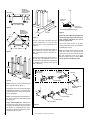
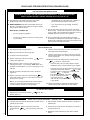
From Thermocouple
Optional ON/OFF
Wall Switch/Rocker Switch
TH
*
Factory Wired
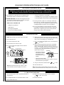
Step 6. Installing the Optional Forced Air
Blower Kit Wiring – A receptacle plate is
provided for the installation of the FAB-1100
forced air blower kit (optional). Electrical
power must be provided to this plate to operate the blower.
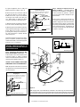
Route a 3-wire, 120Vac power line with control switch to the lower left front corner of the
appliance. Supply wires are to be connected to
the outlet as shown in Figure 12, ensuring that
the polarity (as determined by the colors of the
wires) is exactly as shown. The black and red
wire loop must be left intact, with the mating
connectors connected.
Thermopile
TPTH
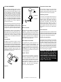
C. When the gas lines are tested and leak free,
be sure to rinse off the leak testing solution.
D. When the gas lines are tested and leak free,
observe the individual tongues of flame on the
burner. Make sure all ports are open and
producing flame evenly across the burner. If
any ports are blocked, or partially blocked,
clean out the ports.
*
TP
B. Brush all joints and connections with the
gas leak test solution to check for leaks. If
bubbles are formed, or gas odor is detected,
turn the gas control knob to the “OFF” position. Either tighten or refasten the leaking
connection and retest as described above.
VF4000-CMN/P Series
Optional Wiring Diagram
Field Wired
* For Rocker Switch Attachment Only.
Figure 11
An external regulator must be used on all propane (L.P.G.) heaters, in addition to the regulator fitted to the heater, to reduce the supply tank
pressure to 13" w.c. (maximum).
OFF/ON Blower
Wall Switch
To Fuse or
Circuit Breaker
Black
WARNING: CONNECTING DIRECTLY TO
AN UNREGULATED PROPANE TANK CAN
CAUSE AN EXPLOSION.
}
Receptacle
White
120V
AC
60Hz
Fireplace
Junction Box
Blower Wiring Diagram
Step 5. Installing the Optional Remote Wall
Switch (VF4000-CMN/P models only) – The
millivolt system comes from the factory wired
as shown in Figure 10. Select a convenient
location for the remote wall switch and connect
the wiring to the appliance (Figure 11 ).
CAUTION: DO NOT CONNECT THE OPTIONAL
REMOTE SWITCH TO A 120V POWER SUPPLY.
Note: The optional rocker switch is mounted to
the appliance and wired in the same way as the
remote wall switch.
Ground Wire
Connection
White
(Supply)
Blower
(Lower)
Outlet
120 Vac
60 Hz
Bipolar
Terminal
Screw
Black
(Supply)
Black
Wire
VF4000-CMN/P Series
Wiring Diagram
If any of the original wire as supplied must be replaced, it
must be replaced with Type AWM 105°C – 18 GA. wire.
From Thermocouple
TH
*
Mating
Connectors
*
Thermopile
TP
Red Wire
TPTH
Figure 12
* For Rocker or ON/OFF Wall Switch Attachment Only.
Note: Supply wires may be alternatively connected to the outlet using the screw terminals,
however the black supply wire must be ganged wired to the same terminal that the pre-wired black
wire is attached to and the white supply wire must be connected to the opposite side of the outlet.
Figure 10
NOTE: DIAGRAMS & ILLUSTRATION NOT TO SCALE.
7