1
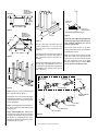
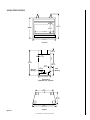
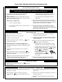
Back Wall of
Chase/Enclosure
Including Finishing
Materials If Any.
Outside Wall
15-1/2"
(394mm)
Control Valve
(Standard)
37" (940mm)
Lower Control
Compartment Door
Figure 4
Back Wall of
Chase/Enclosure
Including Finishing
Materials If Any.
41"
(1041mm)
13-1/2"
(343mm)
29"
(737mm)
37" (940mm)
58-1/2" (1486mm)
Figure 5
3"
(76 mm)
7"
(178 mm)
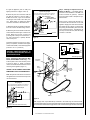
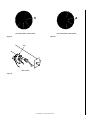
Figure 9
Figure 7
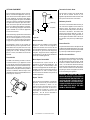
The gas control valve is located in the lower
control compartment. To access the valve
open the lower control compartment door
(Figure 9 ).
The regulator has a 3/8" NPT thread inlet port
and is fitted with a 3" (76 mm) long nipple, ³⁄₈"
NPT on both ends. Plan the connections accordingly.
We recommend that the gas line be routed for
the right side of the appliance to ensure adequate access to the rear lower compartment
for installation and servicing of the optional
FAB-1100 blower.
Secure all joints tightly using appropriate
tools and sealing compounds (ensure propane resistant compounds are used in
propane applications).
Turn on gas supply and test for gas leaks,
using a gas leak test solution (also referred to
as bubble leak solution).
Note: Using a soapy water solution (50% dish
soap, 50% water) is an effective leak test
solution but it is not recommended, because
the soap residue that is left on the pipes/
fittings can result in corrosion over time. Never
use an open flame to check for leaks.
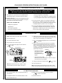
37-1/4"
(946 mm)
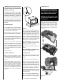
Gas Flex Line Kit, Model GFLV
15-1/2"
(394 mm)
3/8" NPT x 3/8"
Flare Fitting
1/2" x 3/8" Flare
Shut-Off Valve
Gas Valve
37"
(940 mm)
3/8" Flex Tubing
Figure 6
Step 2. Route a 1/2" (13 mm) gas line along the
left or right side framing (Figure 7 ).
3/8" Nipple, Standard
with all Units
All appliances have a 3" long 3/8" NPT nipple
installed at the regulator. To quickly and easily
complete the gas line routing, use the gas flex
line kit, Model GFLV.
Step 3. Position appliance into prepared framing, secure with 6d nails at the nailing flange
along each side.
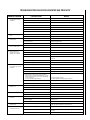
3/8" Union
Gas Stub
3/8" Close Nipple
3/8" Shut-Off Valve
1/2" x 3/8" Reducer
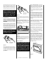
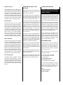
Step 4. Connecting Gas Line – Make gas line
connections. All codes require a shut-off valve
mounted in the supply line. Figure 8 illustrates
two methods for connecting the gas supply.
Installation methods and materials must be in
compliance with local codes.
6
Figure 8
NOTE: DIAGRAMS & ILLUSTRATION NOT TO SCALE.