1
INSTRUCTION MANUAL
OUTDOOR COLOR CAMERA
C-CV44-3 NTSC
C-CV44-3 PAL
Thank you for purchasing TOA’s Outdoor Color Camera. Please carefully follow the instructions in this
manual in order to ensure long, trouble-free use of your color camera.
TABLE OF CONTENTS
1. SAFETY PRECAUTIONS ................................................................................ 3
2. GENERAL DESCRIPTION ............................................................................. 4
3. HANDLING PRECAUTIONS .......................................................................... 4
4. NOMENCLATURE ............................................................................................. 5
5. INSTALLATION AND CONNECTIONS ...................................................... 6
6. ADJUSTMENT ................................................................................................... 10
7. ABOUT THE MODE SETTING SWITCH
7.1. Adjustment Switch ........................................................................................... 13
7.2. Backlight Compensation Switch ...................................................................... 13
7.3. Shutter Speed Switch ...................................................................................... 13
8. IF YOU THINK THERE IS A FAILURE: (TROUBLESHOOTING) ..... 14
9. SPECIFICATIONS ............................................................................................ 15
Accessories ............................................................................................................. 15
2
1. SAFETY PRECAUTIONS
• Before installation or use, be sure to carefully read all the instructions in this section in order to ensure long,
trouble-free operation.
• Be sure to follow all the precautionary instructions in this section, which contain important warnings
regarding safety.
• After reading, keep this manual handy for future reference.
Safety Symbol and Message Conventions
Safety symbols and messages are used in this manual to prevent bodily injury and property damage which
could result from mishandling. Before doing anything else, read this section first so you are thoroughly aware
of the potential safety hazards as well as understanding the safety symbols and messages.
WARNING
Indicates a potentially hazardous situation which could result in death or
serious personal injury if ignored or mishandled.
• This is a class A product. In a domestic environment this product may cause radio interference in which case
the user may be required to take adequate measures.
• To prevent lightning strikes, install the unit at least 5 meters away from a lightning conductor yet within the
protective range (angle of 45 degrees) of the lightning conductor. Lightning may cause a fire, electric shock,
or personal injury.
• Install the unit only in a location that can structurally support the weight of the unit and the mounting bracket.
Doing otherwise may result in the unit falling down and causing personal injury.
• Use nuts and bolts that are appropriate for the ceiling’s wall’s structure and composition. Failure to do so
may cause the unit to fall, resulting in material damage and possible personal injury.
• Tighten each nut and bolt securely. Ensure that the bracket has no loose joints after installation to prevent
accidents that could result in personal injury.
• Have the unit periodically checked by the dealer from where it was purchased. Should the unit or its mounts
corrode or structurally deteriorate, the unit could fall down, possibly resulting in personal injury.
• Should any of the following irregularities be found during use, immediately switch off the power, disconnect
the power supply cord from the AC outlet and contact your TOA dealer. Do not attempt to further use the unit
because a fire or electric shock may result.
• If you detect smoke or a strange smell coming from the unit.
• If water or a foreign object enters the unit.
• If the unit falls or the unit case breaks.
• If the power supply cord is damaged (exposure of core or disconnection).
• If no image is displayed on the screen.
• Do not insert nor drop metal pieces or flammable materials into the unit’s ventilation slots as this may result
in fire or electric shock.
CAUTION
Indicates a potentially hazardous situation which could result in
moderate or minor personal injury, and/or property damage if ignored
or mishandled.
• Leave the unit’s installation to the dealer from where the unit was purchased because the installation
requires expert knowledge. Inadequate installation may cause the unit to fall, possibly resulting in personal
injury.
• Do not hang from the unit, as the unit may fall, possibly resulting in personal injury.
• Avoid installing the unit in locations exposed to sea breeze or corrosive gas. The unit or its mounts may be
subject to corrosion, which could cause the unit to fall, possibly resulting in personal injury.
• Do not touch the unit’s sharp metal edge, as this could result in personal injury.
3
NTSC version complies with Part 15 of the FCC Rules.
Note
This equipment has been tested and found to comply with the limits for a Class A digital device,
pursuant to Part 15 of the FCC Rules. These limits are designed to provide reasonable protection
against harmful interference when the equipment is operated in a commercial environment. This
equipment generates, uses, and can radiate radio frequency energy and, if not installed and used in
accordance with the instruction manual, may cause harmful interference to radio communications.
Operation of this equipment in a residential area is likely to cause harmful interference in which case the
user will be required to correct the interference at his own expense.
Modifications
Any modifications made to this device that are not approved by TOA Corporation may void the authority
granted to the user by the FCC to operate this equipment.
Underwriters Laboratories Inc. (UL) has not tested the performance or reliability of the security aspects
of this product. UL has only tested for fire, shock or casualties as outlined in UL's Standard(s) for
Safety. UL Certification does not cover the performance or reliability of the security hardware and
security operating software. UL MAKES NO REPRESENTATIONS, WARRANTIES OR
CERTIFICATIONS WHATSOEVER REGARDING THE PERFORMANCE OR RELIABILITY OF ANY
SECURITY RELATED FUNCTIONS OF THIS PRODUCT.
2. GENERAL DESCRIPTION
The TOA C-CV44-3 is an outdoor-use high-resolution camera equipped with a 1/4” CCD. Its water-resistant
design permits it to be mounted to outdoor walls or ceilings with no need to protect it from rain and the
elements. Because the camera angle can be freely moved, a wide range of subjects can be monitored,
regardless of installation location. The C-CV44-3 is designed to operate on 24 V AC or 12 V DC, which are
supplied by an external power supply unit. Since its 2X vari-focal, auto-iris lens is built inside the camera, its
angle of view can be manually adjusted.
3. HANDLING PRECAUTIONS
• Do not point the camera toward the sun or other strong lighting or reflected light.
• Avoid jarring or striking the camera, as the camera may fail.
• Install the camera in locations where the temperature range does not exceed –10°C to +50°C, and no dew
condensation is formed.
• To clean, wipe with a soft, dry cloth. Never use benzene, thinner or chemically-treated towel to avoid
damage to the camera’s finish.
• To clean the lens, use a camera blower or lightly wipe with lens cleaning paper.
• Picture quality may suffer if camera cables are wired close to other electrical equipment, such as fluorescent
lamps. In such cases, reroute the wiring.
• Monitor screen pictures may become distorted or roll if the camera is used in locations influenced by strong
electrical or magnetic fields from television transmission antennas, motors or transformers. In such cases,
install the cables inside sheet steel cable conduit.
• Use the external power supply unit of the following rating when the camera is operated on 12 V DC.
12 V DC, over 1.0 A
4
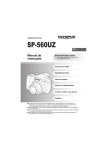
4. NOMENCLATURE
[External View]
6
1
7
2
3
4
5
[Figure showing the camera from which the sunshade, front
cover, and mounting bracket have been removed]
8
9 10 11 12
13
[Figure showing the camera
from which the water-resistant
cap has been removed]
15
16
OFF ON
F.ADJ
BLC
1/100
SHUTTER
1/60
IRIS
MONITOR OUT
L
H
14
(1) Vari-focal lens
(9) Zoom ring fixing screw
(2) Sunshade
(10) Focus ring fixing screw
(3) Front cover
(11) Focus ring
(4) Mounting bracket
(standard accessory)
(5) Security wire entry hole
(12) Zoom ring
(6) Sunshade fixing screw
(14) Iris control
(7) Camera mounting bolt
(standard accessory)
(8) Monitor output terminal
(RCA pin jack)
(15) Cable with water-resistant cap
(standard accessory)
(16) Camera input/output terminal
(13) Mode setting switch
5
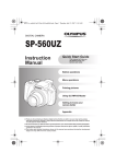
5. INSTALLATION AND CONNECTIONS
[Wall mounting example]
[Ceiling mounting example]
Bracket mounting bolt
(M8 or W 3/8)
Security wire
entry hole
Camera mounting bolt
Washer-installed M8 x 14mm hex bolt
(standard accessory)
WARNING
Install the unit only in a location that can structurally support the weight
of the unit and the mounting bracket. Doing otherwise may result in the
unit falling down and causing personal injury.
Note: Attach the security wire as required. Carefully check to confirm the cable length, cable diameter, and
hook strength, since the shock produced by a camera dropping is very high.
1. Confirm the mounting bracket’s installation location, and determine its mounting direction and position.
Three mounting methods are possible, depending on the installation location.
120º
Used in mounting example 3.
76 mm
Used in mounting
examples 1 and 2.
96 mm
12 mm
4 -ø6.5 mm
ø50 mm
70 mm
97.6 mm
6
ø10.5 mm
[Mounting Example 1] Ceilings or walls
[Mounting Example 3] Ceilings or walls
Use this method when the camera angle does not
need to be adjusted after camera installation is
completed.
[Mounting Example 2] Walls
Use this method when the camera orientation cannot
be sufficiently adjusted in Mounting Example 1.
Note: If the bracket is only fixed at one place using
the bracket mounting bolt, the bracket could
rotate or the bolt could become loose. To
prevent this, be sure to securely fix the bracket
at two more places using self-tapping screws
or other anti-rotation type screws.
Up
Down
2. Install female-thread anchors in the ceiling or wall and mount the camera mounting bracket.
Female-thread anchor
M8 or W 3/8
Ceiling
Mounting bracket
Female-thread anchor
M8 or W 3/8
Ceiling
Mounting bracket
Anti-rotation screw
(such as self-tapping screws)
Plain washer
Plain washer
Spring washer
Spring washer
Bracket mounting bolt
M8 or W 3/8
Bracket mounting bolt
M8 or W 3/8
7
3. Attach the camera to the mounting bracket.
Use the supplied insulation spacers, camera mounting bolts (washer-installed M8 x 14mm hex bolt) to
attach.
Note: Because the induced voltage and noise may be generated at the camera mounts, depending on the
installation environment, be sure to use insulation spacers and washers when attaching. Also, never
remove the insulation washers attached to the mounting bracket.
Mounting bracket
Camera mounting bolt
Washer-installed M8 x 14mm hex bolt
Insulation spacer
Insulation washers are attached to
the mounting bracket.
4. Connect the connector.
Connect the connector of the supplied cable with the water-resistant cap to the camera’s Input/Output
terminal, then tighten the connector’s lock screw.
Notes
• Be sure to fully insert the connector to prevent rainwater from getting in the Camera.
• Wrap the self-adhesive type butyl rubber tape round cable joints to prevent rainwater from entering.
Connector
UL1095#22 Black/ White (Nonpolar)
(water-resistant type)
Water-resistant cap
Cable joint section
Connects to power supply source
Connects to monitor
Lock screw
Camera Input/
Output terminal
8
BNC jack
Supplied cable
BNC plug
5. Mount the water-resistant cap to the camera.
Note: If there is a gap between the water-resistant cap and the mounting surface, water can get in and
expose the connector to corrosion. To avoid equipment failures, check to be sure that the waterresistant cap is attached correctly.
Fit the watertight cap
(shaded section)
securely to the camera.
6. Connect the camera to the monitor and power supply source.
Refer to the following figure to make connections.
Monitor
: BNC plug
Video input
Video output
24 V AC or 12 V DC
Use the external power supply unit of the following rating
when the camera is operated on 12 V DC.
12 V DC, over 1.0 A
Camera Input/Output terminal
9
6. ADJUSTMENT
1. Detach the sunshade and front cover after completing camera mounting and connections.
[Removing the sunshade]
[Removing the front cover]
Loosen the two sunshade
fixing screws.
Turn the front cover in the
direction indicated by the
arrow to remove.
Pull out the sunshade
after rotating.
Front cover
2. Connect the Monitor output terminal to the monitor.
Note: The camera will not operate, even if this terminal is connected to the camera drive.
3. Switch on the power to the camera, permitting a picture to be viewed on the monitor.
4. Set the Mode setting switch for the best possible picture reproduction, depending on the installation
conditions.
• Set the Shutter speed switch to the ON position when light flicker is an annoyance.
• Set the Backlight compensation switch to the ON position when a subject appears blacked-out.
For more information on these switches, refer to p. 13; “About the Mode Switch.”
10
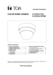
5. Adjust the camera angle.
• The camera angle can be adjusted by loosening both the bracket and camera mounting bolts.
• To adjust the picture tilt, rotate the shadowed section shown in the figure below so that its projection appears
on top.
Note: Horizontal camera angles cannot be adjusted in the Example 3 installation described on p. 7.
Bracket mounting
bolt
Focus ring
Mode setting switch
Horizontal angle
± 60º
Projection
Zoom ring
OFF
1/60
ON
F. ADJC
BL 0
1/10 TER
SHUT
IRIS
H
L
Camera mounting bolt
Iris control
Picture tilting: ± 90º
(Rotate the shaded section)
Vertical angle: 90º
(In the case of ceiling mounting)
6. Adjust the angle of view with the Zoom ring and adjust the focus with the Focus ring for the best possible
picture reproduction.
Notes
• Since the Iris control (for sensitivity adjustment) is factory-preset to an optimum position for general use,
avoid tampering with it in normal conditions. Turning the control unnecessarily could cause reduced picture
quality or equipment failure. When the Iris control needs to be readjusted to match a specific subject, first set
both the Adjustment switch and the Backlight Correction switch of the Mode setting switch to the OFF
position, then adjust the control to an optimum level. After adjustment, place a hand over the lens for several
seconds and then release to check the lens for correct iris operation.
• If the focus is adjusted for a subject under good lighting conditions, the subject may go out of focus when
conditions become dark. To avoid this, adjust the lens focus after setting the Adjustment switch of the Mode
setting switch to the ON position. Be sure to switch it back to the OFF position after completing lens
adjustment.
7. After completing all necessary adjustments, disconnect the RCA pin jack connected to the Monitor output
terminal in Step 2.
8. Tighten both the bracket and camera mounting bolts, then mount the front cover.
Note: If the front cover is not securely fastened, its water-resistant properties will be compromised, possibly
resulting in equipment failure.
11
9. Insert the sunshade from the front of the camera, as shown in the figure below, and secure it using the
sunshade fixing screw (2 places).
[Ceiling mounting example]
Sunshade fixing screw
(washer-installed M3 x 8mm pan head screw)
Slot for sunshade fixing screw insertion
Sunshade
Sunshade fixing screw
After inserting, rotate the sunshade clockwise until it stops (as shown in the figure),
then secure with the sunshade fixing screws.
12
7. ABOUT THE MODE SETTING SWITCH
Set the Mode Setting switch for the best possible picture reproduction depending on installation conditions.
Mode Setting Switch
(Factory-preset position)
OFF ON
OFF
Adjustment switch
Backlight Compensation switch
Shutter Speed switch
ON
F. ADJ
BLC
1/100
SHUTTERR
1/60
IRIS
L
H
(NTSC) 1/60
(PAL) 1/50
1/100
1/120
7.1. Adjustment Switch
Set this switch when adjusting the lens focus. (Provides the same effect as when using the ND filter.)
OFF ON
Standard position :
Set to OFF after lens adjustment completion. Set to this position during normal use.
OFF ON
Adjustment position (during adjustment) :
Use this position when focusing the lens. If the focus is adjusted for a subject under
good lighting conditions, the subject may go out of focus when conditions become
dark. Set the Adjustment switch to ON only when performing focus adjustment.
Note: The color of the screen may periodically vary under fluorescent lighting when the
Adjustment switch is set to ON.
7.2. Backlight Compensation Switch
Set this switch so that the subject is not displayed in black when backlit.
OFF ON
OFF ON
Standard position :
Set to this position during normal use. Backlight Compensation function does not
operate when the switch is set to this position.
Backlight Compensation position (when backlit) :
This position prevents images from being displayed in black when the image is
backlit.
7.3. Shutter Speed Switch
Set this switch to the ON position when annoying screen image flicker is detected.
OFF ON
OFF ON
Standard position :
Set to this position during normal use.
Shutter Speed position :
Annoying screen flicker may result under fluorescent lighting in areas operating with a
power frequency of 50 Hz (NTSC) or 60 Hz (PAL). In such cases, set the Shutter
Speed switch to the ON position to permit a flicker-free picture to be viewed.
Note: If the Shutter Speed switch is set to the ON position, sensitivity is reduced compared
to operation in the OFF position. When using the camera in a dark location, or where
light flicker is not an annoyance, set the switch to the OFF position.
13
8. IF YOU THINK THERE IS A FAILURE: (TROUBLESHOOTING)
Symptom
Camera images are
not displayed on the
monitor.
Pictures are not clear.
Subject under dark
lighting conditions
goes out of focus.
Pictures are too bright.
Pictures are curved.
The color of the picture
periodically varies.
Noise appears on the
screen.
14
Possible Cause
Cables are not correctly connected.
The BNC plug is not correctly
soldered.
Lens is not properly focused.
Lens is dirty.
Monitor’s image black level is not
correctly adjusted.
If the focus is adjusted for a subject
under good lighting conditions, the
subject may go out of focus when
conditions become dark. (Influence
of the depth of field)
The position of the Iris control has
been changed from the factorypreset position.
Lens view angle is set to wide angle
("W" side).
The Adjustment switch is set to the
ON position.
Camera cables are wired close to
other electrical equipment, such as
fluorescent lamps.
Insulation spacers are not installed.
Remedy
Connect correctly.
Solder correctly.
Adjust the lens.
Wipe the lens.
Adjust correctly by following the instructions
in the instruction manual for the monitor.
Set the Adjustment switch of the Mode
setting switch to the ON position, then
focus the lens again. (Refer to Step 6 on p.
11.) Be sure to shift the Adjustment switch
back to the OFF position after adjustment
completion.
Set the Iris control to an optimum position.
(Refer to Step 6 on p. 11.)
The C-CV44-3 camera employs the wide
angle lens. Pictures become curved when
the view angle is set to the W side, but this
is not a failure.
Shift the Adjustment switch of the Mode
setting switch back to the OFF position.
Reroute the wiring.
Install the supplied insulation spacers
correctly. (Refer to Step 3 on p. 8.)
9. SPECIFICATIONS
Model No.
Power Source
Power Consumption
Image Device
Number of Effective Pixels
Scanning System
Scanning Frequency
Monitor Output
Video Output
Synchronizing System
Resolution
S/N Ratio
Minimum Illumination
White Balance Mode
Focal Length
Maximum Aperture Ratio
Iris
Angle of View
Control Switch
Other Functions
Shutter Speed
Water Resistance
Operating Temperature
Operating Humidity
Finish
Dimensions
Weight
C-CV44-3 (NTSC)
C-CV44-3 (PAL)
24 V AC, 50/60 Hz, or 12 V DC
2W
1/4” IT-CCD
768 (H) x 494 (V), 380,000 pixels
752 (H) x 582 (V), 440,000 pixels
2:1 interlace
15.734 kHz (H), 59.94 Hz (V)
15.625 kHz (H), 50 Hz (V)
VBS1.0 V(p-p), 75 Ω, RCA pin jack
VBS1.0 V(p-p), 75 Ω, water-resistant connector
Internal synchronization
H: 480 lines (center), V: 350 lines
H: 470 lines (center), V: 410 lines
48 dB
3 lx (50 IRE)
3 lx (350 mV)
ATW
f=3.0 mm – 6.0 mm
1:1.2 – 1.5
Automatic iris
71.9º– 36º(H), 52º– 26.8º(V)
ON/OFF (for focus adjustment)
Backlight compensation, shutter speed, iris adjustment
1/60,1/100
1/50,1/120
Equivalent to IP66
– 10ºC to + 50ºC
Under 90% RH (no dew condensation)
Front cover,rear cover,sunshade : Aluminum, light gray, paint
Mounting bracket : Stainless steel, light gray, paint
ø92 x 236 (D) mm
1.1 kg
The specifications of this camera are subject to change without notice.
• Accessories
Mounting bracket ................................................................................ 1
Cable with water-resistant cap (2 m) .................................................. 1
Camera mounting bolt ........................................................................ 2
(washer-installed M8 x 14mm stainless steel hex bolt)
Insulation spacer.................................................................................. 2
15
Printed in Vietnam
133-12-875-4F