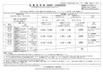
1
OWNER'S MANUAL
62" DX CABINET
32"STD CABINET
TABLE OF CONTENTS
TABLE OF CONTENTS ..................................................................................................................................i
INTRODUCTION ............................................................................................................................................ii
1
HANDLING PRECAUTIONS ..............................................................................................................1
2
PRECAUTIONS REGARDING INSTALLATION LOCATION.............................................................2
INTRODUCTION
BEFORE USING THE PRODUCT, BE SURE TO READ THE FOLLOWING:
2-1 LIMITATIONS OF USAGE ...........................................................................................................2
2-2 OPERATION AREA .....................................................................................................................2
3
PRECAUTIONS REGARDING PRODUCT OPERATION ..................................................................3
3-1 BEFORE OPERATION ...............................................................................................................3
3-2 DURING OPERATION (PAYING ATTENTION TO CUSTOMERS) ............................................4
4
PART DESCRIPTIONS ......................................................................................................................5
5
ACCESSORIES .................................................................................................................................6
6
ASSEMBLY AND INSTALLATION .....................................................................................................7
7
PRECAUTIONS WHEN MOVING THE MACHINE ..........................................................................17
7-1 MOVING THE MACHINE ..........................................................................................................17
7-2 SEPARATING THE MAIN CABINET .........................................................................................17
8
GAME DESCRIPTION ......................................................................................................................19
9
EXPLANATION OF TEST AND DATA DISPLAY .............................................................................20
9-1 PUSH SWITCH AND COIN METER ........................................................................................20
9-2 SYSTEM TEST MODE ..............................................................................................................21
9-3 GAME TEST MODE ..................................................................................................................21
11
10
CONTROL UNIT ...............................................................................................................................27
10-1 HOW TO REMOVE CONTROL UNIT .....................................................................................27
10-2 ADJUSTING OR CHANGING THE X AXIS VOLUME .............................................................29
10-3 ADJUSTING OR CHANGING THE Y AXIS VOLUME .............................................................31
10-4 REPLACING THE TRIGGER SWITCH ...................................................................................35
10-5 GREASING .............................................................................................................................37
10-6 ADJUSTMENT OF VIBRATION NOISE ..................................................................................38
11
PERIODIC INSPECTION ..................................................................................................................39
12
TROUBLESHOOTING......................................................................................................................41
13
GAME BOARD .................................................................................................................................47
13-1 HOW TO REMOVE GAME BOARD ........................................................................................47
13-2 COMPOSITION OF THE GAME BOARD ................................................................................48
14
DESIGN RELATED PARTS ..............................................................................................................49
15
PARTS LIST .....................................................................................................................................51
16
WIRE COLOR CODE TABLE ...........................................................................................................66
17
CABINET WIRING DIAGRAM
i
INTRODUCTION
INTRODUCTION
This manual is intended to provide detailed descriptions together with all the necessary information covering the general operation of
electronic assemblies, electro-mechanicals, servicing control, spare parts, etc. for the product, "LET’S GO JUNGLE! - LOST ON
THE ISLAND OF SPICE."
This manual is intended for the owners, personnel and managers in charge of operation of the product.
Operate the product after carefully reading and sufficiently understanding the instructions.
In the unlikely event that the product does not function correctly, DO NOT allow anyone other than a technician to touch the internal system. Turn off the power to the machine, making sure to unplug the electrical cord from the outlet, and contact the office listed
below or the point-of-purchase for this product.
Use of this product is unlikely to cause physical injuries or damage to property. However, points that require special attention are indicated by bold text, the word "IMPORTANT" and the symbol below.
Indicates important information that, if ignored, may result in the mishandling of
the product and cause faulty operation or damage to the product.
Sega Amusements U.S.A., Inc.
800 Arthur Avenue, Elk Grove Village, IL 60007-5215, U.S.A.
TEL: 1-847-364-9787
TOLL FREE: 1-888-877-2669
FAX: 1-847-427-1065
SPECIFICATIONS
Width and Depth
Height:
Weight:
Power, maximum current:
Monitor:
62"DX = 60.5" [W] x 109" [D] / 32"STD = 33" [W] x 44.5" [D]
62”DX = 86.4" / 32"STD = 87"
62”DX = 1,498 lbs. / 32”STD = 382 lbs
Input 120VAC, 60Hz. >> 62”DX = 6.3 A / 32”STD = 4.5 A
62”DX = 62 inch DLP Projector / 32”STD = 32”LCD Display
NOTE: The contents herein described are subject to change without notice.
Definition of 'Site Maintenance Personnel or Other Qualified Individuals'
Procedures not described in this manual or marked as ‘to be carried out by site maintenance personnel or other
qualified professionals’ should not be carried out by personnel without the necessary skill or technology. Work carried out by unqualified persons may cause serious accidents, including electrocution.
Parts replacement, maintenance inspections and troubleshooting should be carried out by site maintenance personnel or other qualified
professionals. This manual includes directions for potentially dangerous procedures which should only be carried out by professionals
with the appropriate specialized knowledge.
The site maintenance personnel or other qualified professionals mentioned in this manual are defined as follows:
Site maintenance personnel:
Individuals with experience in maintaining amusement equipment, vending machines, etc., working under the supervision of the
owner/operator of this product to maintain machines within amusement facilities or similar premises by carrying out everyday procedures such as assembly, maintenance inspections, and replacement of units/expendable parts.
Activities to be carried out by site maintenance personnel:
Amusement equipment/vending machine assembly, maintenance inspection and replacement of units/expendable parts.
Other qualified professionals:
Persons employed by amusement equipment manufacturers, or involved in design, production, testing or maintenance of amusement
equipment. The individual should have either graduated from technical school or hold similar qualifications in electrical/electronics/
mechanical engineering.
Activities to be carried out by other qualified professionals:
Amusement equipment/vending machine assembly, repair/adjustment of electrical/electronic/mechanical parts.
ii
1 HANDLING PRECAUTIONS
When installing or inspecting the machine, be very careful of the following points and pay attention to ensure that the player can
enjoy the game safely.
Non-compliance with the following points or inappropriate handling running counter to the cautionary matters herein stated can
cause personal injury or damage to the machine.
1
● To avoid an electric shock or short circuit, do not plug in or unplug quickly.
● To avoid an electric shock, do not plug in or unplug with a wet hand.
● Do not expose power cords or earth wires on the surface, (floor, passage, etc.). If exposed, the power cords
and earth wires are susceptible to damage. Damaged cords and wires can cause an electric shock or short
circuit.
● To avoid causing a fire or an electric shock, do not put things on or damage the power cords.
● When or after installing the product, do not unnecessarily pull the power cord. If damaged, the power cord
can cause a fire or an electric shock.
● In case the power cord is damaged, ask for a replacement through where the product was purchased from
or the office herein stated. Using the cord as is damaged can cause fire, an electric shock or leakage.
● Be sure to perform grounding appropriately. Inappropriate grounding can cause an electric shock.
HANDLING PRECAUTIONS
● Before performing work, be sure to turn the power off. Performing the work without turning the power off can
cause an electric shock or short circuit. In the case work should be performed in the status of power on, this
manual always states to that effect.
● Be sure to use fuses meeting the specified rating. Using fuses exceeding the specified rating can cause a fire
or an electric shock.
● Be sure that connections such as IC BD are made properly. Insufficient insertion can cause an electric shock.
● Specification changes, removal of equipment, conversion and/or addition, not designated by SEGA are not
permitted.
- Failure to observe this may cause a fire or an electric shock. Non-compliance with this instruction can
have a bad influence upon physical conditions of the players or the onlookers, or result in injury during
play.
- SEGA shall not be held responsible for damage, compensation for damage to a third party, caused by
specification changes not designated by SEGA.
● Do not perform any work or change parts not listed in this manual. Doing so may lead to an accident. If you
need to perform any work not listed in this manual, request work from the office indicated in this manual or
the point of purchase, or inquires for details.
● Be sure to perform periodic maintenance inspections herein stated.
● For the IC board circuit inspections, only the logic tester is allowed. The use of a
multiple-purpose tester is not permitted, so be careful in this regard.
● The projector is employed for this machine. The projector’s screen is susceptible to
damage, therefore, be very careful when cleaning the screen. For details, refer to
the section “Projector.”
● Static electricity from your body may damage some electronics devices on the IC
board. Before handling the IC board, touch a grounded metallic surface so that the
static electricity can be discharged.
● Some parts are not designed and manufactured specifically for this game machine.
The manufacturers may discontinue, or change the specifications of such generalpurpose parts. If this is the case, SEGA cannot repair or replace a failed game
machine whether or not a warranty period has expired.
CONCERNING THE STICKER DISPLAY
This SEGA product has stickers attached describing the product manufacture No. (Serial No.) and Electrical Specifications. It
also has a Sticker describing where to contact for repair and for purchasing parts.
When inquiring about or asking for repairs, mention the Serial No. and Name of Machine indicated on the Sticker. The Serial
Number indicates the product register. Identical machines could have different parts depending on the date of production. Also,
improvements and modifications might have been made after the publication of this manual. In order to ensure you order the
correct parts, mention the Serial No. when contacting the applicable places.
CONCERNING WARNING DISPLAYS
This SEGA product has warning displays on stickers, labels and/or printed instructions adhered/attached to or incorporated in
the places where a potentially hazardous situation could arise. The warning displays are intended for accident prevention for customers and for avoiding hazardous situations relating to maintenance and servicing work. Some portions of the cabinet contain
high voltage and may cause accidents if touched. When performing maintenance, be very careful of the warning displays. It is
especially important that any complex repair and replacement work not mentioned herein should be performed by those technical
personnel who have knowledge of electricity and technical expertise.
In order to prevent accidents, caution any customer ignoring the warnings to cease and desist immediately.
1
2 PRECAUTIONS REGARDING INSTALLATION LOCATION
This product is an indoor game machine. Do not install it outside. Even indoors, avoid installing in places mentioned below so as not to cause a fire, electric shock, injury and/or malfunction.
2
- Places subject to rain or water leakage, or places subject to high humidity in the proximity of an indoor
swimming pool and/or shower, etc.
PRECAUTIONS REGARDING INSTALLATION LOCATION
- Places subject to direct sunlight, or places subject to high temperatures in the proximity of heating units,
etc.
- Places filled with inflammable gas or vicinity of highly inflammable/volatile chemicals or hazardous matter.
- Dusty places.
- Sloped surfaces.
- Places subject to any type of violent impact.
- Vicinity of anti-disaster facilities such as fire exits and fire extinguishers.
- The operating (ambient) temperature range is not from 5°C to 30°C.
2-1 LIMITATIONS OF USAGE
● Be sure to check the Electrical Specifications. Ensure that this product is compatible with the location’s power
supply, voltage, and frequency requirements. A plate describing Electrical Specifications is attached to the
product. Non-compliance with the Electrical Specifications can cause a fire and electric shock.
● This product requires a breaker and earth mechanism as part of the location facilities. Using the product without these can cause a fire and electric shock.
● Ensure that the indoor wiring for the power supply is rated at 15 A or higher (AC single phase 100 V ~ 120 V
area), and 7 A or higher (AC 220 V ~ 240 V area). Non-compliance with the Electrical Specifications can
cause a fire and electric shock.
● Be sure to use an independent power supply equipped with an earth leakage breaker. Using a power supply
without an earth leakage breaker can cause an outbreak of fire if a power surge occurs.
● Putting many loads on one electrical outlet can cause generation of heat and a fire resulting from overload.
● When using an extension cord, ensure that the cord is rated at 15 A or higher (AC 100 V ~ 120 V area) and 7
A or higher (AC 220 V ~ 240 V area). Using a cord rated lower than the specified rating can cause a fire and
electric shock.
2-2 OPERATION AREA
● For the operation of this machine, secure a minimum area of 116”(W) x 156”(D) for 62”DX, 81”(W) x 103”(D) for
32”UR. If the machine rolls during play it could lead to serious injury, especially if anyone is hit on the head.
You must secure the space specified in this document.
● Be sure to provide sufficient space specified in this manual. Do not allow objects to block the ventilation
ports. It can cause generation of heat and a fire.
● SEGA shall not be held responsible for damage or compensation for damage to a third party, resulting from
the failure to observe this instruction.
● If the machine does not fit through the entryway to the installation location, do not disassemble it without first
consulting the instructions. If the machine still does not fit through the entryway after following the procedures
in this manual, contact your retailer or the office listed in this manual.
To install this product, the entrance must be at least 48.8” in width and 78” in height.
2
3 PRECAUTIONS REGARDING PRODUCT OPERATION
To avoid injury and trouble, be sure to pay attention to the behavior of visitors and players.
3-1 BEFORE OPERATION
3
● To ensure maximum safety for the players and the customers, ensure that where the product is operated has
sufficient lighting to allow any warnings to be read. Operation under insufficient lighting can cause bodily
contact with each other, hitting accident, and/or trouble between customers.
● Be sure to perform appropriate adjustment of the monitor (projector). For operation of this machine, do not
leave monitor’s flickering or deviation as is. Failure to observe this can have a bad influence upon the players’ or the customers’ physical conditions.
● It is suggested to ensure a space allowing the players who feel sick while playing the game to take a rest.
● Check if all of the adjusters are in contact with the surface. If they are not, the Cabinet can move and cause
an accident.
● Do not put any heavy item on this product. Placing any heavy item on the product can cause a falling down
accident or parts damage.
● Do not climb on the product. Climbing on the product can cause falling down accidents. To check the top
portion of the product, use a step ladder.
● When using a stepladder or stool while working, do not hold onto the billboard carrier (the round pipe section). Holding or hanging off this may bend it out of shape or damage it, and could lead to a fall or an accident.
● To avoid electric shock, check to see if door & cover parts are damaged or omitted.
● To avoid electric shock, short circuit and/or parts damage, do not put the following items on or in the periphery of the product.
[Flower vases, flowerpots, cups, water tanks, cosmetics, and receptacles/containers/vessels containing
chemicals and water.]
PRECAUTIONS REGARDING PRODUCT OPERATION
In order to avoid accidents, check the following before starting the operation:
● To avoid injury, be sure to provide sufficient space by considering the crowd situation at the installation location. Insufficient installation space can cause customers to bump into each other, causing trouble.
● Every day when cleaning the Control Unit (Gun), inspect the gun and make sure that there are no scratches
or cracks in the surface, and that the fastening screws are not loose. If the game is played with scratches,
cracks or loose screws, it can cause injuries to the player or to people nearby.
Ensure that the trigger is functioning properly.
Ensure that the screws are not
loose and are all present.
Ensure that the casing is free of
scratches and cracks.
Ensure that the screws are not
loose and are all present.
● When you clean the cabinet each day, always make sure that there is nothing placed on the seats and that
they are not damp or wet. The construction of this product may allow for willful misconduct by players.
3
To ensure customers enjoy playing the game, clean the Control Unit regularly. If
there is any dirt buildup, the trigger may not return properly after being pulled.
3
PRECAUTIONS REGARDING PRODUCT OPERATION
3-2 DURING OPERATION (PAYING ATTENTION TO CUSTOMERS)
To avoid injury and trouble, be sure to pay attention to the behavior of visitors and players.
● For safety reasons, do not allow any of the following people to play the game.
- Those who require supporting devices, etc., to walk.
- Those who have high blood pressure or a heart problem.
- Those who have experienced muscle convulsion or loss of consciousness when playing video games, etc.
- Those who have neck or spinal cord problems.
- Intoxicated persons.
- Pregnant women.
- Persons susceptible to motion sickness.
- Persons who disregard the product’s warning displays.
● Even players who have never been adversely affected by light stimulus might experience dizziness or headache depending on their physical condition when playing the game. Small children are especially likely to
experience these symptoms. Caution guardians of small children to keep watch on their children during play.
● Instruct those who feel sick during play to have a medical examination.
● To avoid injury from falls and electric shocks due to spilled drinks, instruct the player not to place heavy items
or drinks on the product.
● To avoid electric shocks and short circuits, do not allow customers to put hands and fingers or extraneous
matter in the openings of the product or small openings in or around the doors.
● To avoid falls and resulting injury, stop the customer from leaning against or climbing on the product, etc.
● To avoid electric shock and short circuit, do not allow customers to unplug the power plug without a justifiable reason.
● Immediately stop such violent acts as hitting and kicking the product. Such violent acts can cause parts
damage or falling down, resulting in injury due to fragments and falling down.
● Two or more players must never be allowed to play using a single Control Unit. Playing in such a way could
lead to physical injuries.
● When entering or exiting the machine, players may trip over the base. Be sure to warn players who do not
appear to be exercising proper caution.
The interior of the cabinet is hard to see from the outside which may lead to willful misconduct by
players or accidents going unnoticed. When the game is not in use, check the interior at regular
intervals and make sure that nothing has been forgotten or placed on the seats.
4
4 PART DESCRIPTIONS
BILLBOARD
FLUORESCENT LIGHT
BILLBOARD BOX
4
CURTAIN
PART DESCRIPTIONS
SEAT CABINET
MARQUEE
SPEAKER (Left & Right)
62”DX
2P SIDE CONTROL UNIT
1P SIDE CONTROL UNIT
1P SIDE
START BUTTON
2P SIDE
START BUTTON
COIN CHUTE DOOR
CASH BOX DOOR
FIG. 4 Name of Each Part
32”UR
TABLE 4 Major Measurements of Each Unit Upon Purchase = 62”DX
62”DX cabinet
Width x Depth x Height
Cabinet A (Monitor)
61” x 20 3/4” x 71”
Cabinet B (Speaker)
61” × 24 1/4” × 71”
Cabinet C (Control)
61” × 31 1/2”” × 71”
Cabinet D (Seat Assy)
61” × 30” × 71”
Billboard (Assy)
49” × 33” × 14”
5
5 ACCESSORIES
MANUAL LET’S GO JUNGLE: 532-30-300 (1) > This manual
REMOTE CONTROLER & MANUAL FOR TOSHIBA 62”DLP MONITOR > 62”DX only
5
ACCESSORIES
UNIVERSAL POWER CORD 8FT
99-00-017
DVD SOFTWARE KIT (1)
NOTE: We already installed software in CPU. Key Chip also already in CUP mounted. Please keep
DVD Disk for future uses.
KEY CHIP (1)
CUSHION SPONGE
601-11137 (1)
(Protective material)
DVD-ROM (1)
DISC CASE
253-5507-01 (1)
To order the DVD-ROM by itself, use the following part number:
610-0726-0011 (DVD SOFT LGJ BOTH 32”STD AND 62”DX)
6
6 ASSEMBLY AND INSTALLATION
● Perform assembly work by following the procedure herein stated. Failure to comply with the instructions can
cause electric shock.
● Perform assembling as per this manual. Since this is a complex machine, incorrect assembling can cause an
electric shock, machine damage and/or improper functioning as per specified performance.
● Ensure that connectors are properly connected. Improper connections can cause electric shock.
● Be careful not to damage the wires. Damaged wires may cause electric shock or short circuit or present a
risk of fire.
● This work should be carried out by site maintenance personnel or other qualified professionals. Work performed by non-technical personnel can cause a severe accident such as electric shock. Failing to comply
with this instruction can cause a severe accident such as electric shock to the player during operation. If no
one with proper technological expertise is available, request service from the office indicated in this document or the point of purchase so as to ensure safety.
● Provide sufficient space so that assembling can be performed. Performing work in places with narrow space
or low ceiling may cause an accident and assembly work to be difficult.
● To perform work safely and avoid serious accident such as the cabinet falling down, do not perform work in
places where step-like grade differences, a ditch, or slope exist.
● Do not leave power cords or ground wires exposed in areas of heavy foot traffic. Doing so may cause them to
become damaged, possibly resulting in electric shock and/or short circuits. When laying wiring across the
floor, always use safety covers to protect the wires. (Wiring diameter: power cable - approx. φ 8)
● Have a flashlight or another supplementary lighting unit available while working. With indoor lighting alone, the
cabinet interior may be too dark. Working without proper lighting can lead to accidents. It also hinders proper
work performance.
6
ASSEMBLY AND INSTALLATION
● When assembling, more than one person is required. Depending on the assembly work, there are some cases
in which working by one person alone can cause personal injury or parts damage.
● The cabinet has ventilation ports. Be sure not to block them. If they are blocked, heat can build up, leading
to fire. This can also accelerate wearing of parts and malfunctions.
● Secure ample ventilation space around the cabinet. If heat builds up, there could be accidents associated
with heat or smoke generation.
● Do not unnecessarily push the projector. This could cause the unit to tip over.
● This product does not use any connectors other than those connected to and used by the game board when
it leaves the factory. Do not needlessly connect wires to unused connectors. This could lead to overheating,
generation of smoke and burn related injuries.
● Handle molded parts with care. Excessive weight or pressure may cause them to break and the broken
pieces may cause injury.
● To perform the operation safely and accurately you must use a safe, steady footstool or stepladder. Working
without this may lead to a fall and possible injury.
● When connecting the connectors on the DVD wire, you must carefully check the tags on the wire to find the
correct connector. Even when you have the correct connector, you must pay careful attention to the direction and angle of insertion. Attempting to forcefully connect the incorrect connector or connecting a connector at the wrong angle or facing may damage the connector and could lead to overheating and burn
related injuries.
● When attaching or removing doors or lids, be careful that your hand or finger does not get caught in anything.
● Be very careful when handling the projector screen. The screen can be damaged easily and cannot be repaired once damaged. Such damage can only be repaired by
completely replacing the screen.
● Be careful not to damage parts surfaces. In some cases, if such surfaces are damaged,
the part must be replaced; it cannot be reinforced or repaired.
7
The assembly of 62”DX is performed in the following 6 steps.
6
ASSEMBLY AND INSTALLATION
1
CONNECTION OF THE CABINET
2
ATTACHING THE BILLBOARD BOX
3
ATTACHING THE BILLBOARD
4
FIXATION TO INSTALLATION SITE\
5
CONNECTION OF POWER AND GROUND
6
CONFIRMATION OF ASSEMBLY
Tools Required for Assembly Operation
- Philips screwdriver (for Phillips screws)
- A 7, Socket wrench or hexagonal screwdriver (for US standard bolts and nuts)
- Flashlight or other supplementary lighting
- A 24 millimeter spanner (Adjustable spanner)
24mm
- Tamper screw wrench (T-25)
8
- Stepladder
1
CONNECTION OF THE CABINET
1
Move the Cabinet A-B and C-D Cabinet close together.
Perform the connection of the wires between the two cabinets.
Leave a gap of approx 8”. Please Line up top of cabinets by adjusting Leg Leveler before joint.
6
CABINET A-B
8”
ASSEMBLY AND INSTALLATION
NOTE:
PLEASE LINE TOP
OF CABIETS UP BY
ADJUSTING LEG
LEVELERS BEFORE
JOINT CABINETS.
WE RECCOMEND 3
OR MORE PERSONS
TO ASSEMBLE.
FIG. 6-1a
2
Connect the following harness
A) Gun Assy 1P & 2P (Gun harness and Earth wire fdor each assy)
B) Con Door harness w/Earth wire.
C) F.L.Lamp and Speaker harness (Top of cabinet)
Then remove 4 sets of Washer and screws
Harness, 1P Gun Assy
w/earth wire
CABINET A-B
Harness, F.L.Lamp and
Speaker
Harness, 2P Gun Assy
w/earth wire
Please tight Earth wire to Base
bracket of 1P Gun Assy in cabinet C.
Please tight Earth wire to Base
bracket of 2P Gun Assy in cabinet C.
NOTE:
PLEASE REMOVE 4
WASHERS & 4 SCREWS
(T25) FROM HERE. THAT
ARE USED FOR JOINTING
OF CABINET A-B & C-D.
Harness, Coin Door
w/earth wire
Please tight Earth wire with
screw of coin door frame in cabinet C.
FIG. 6-1b
9
3
Joint Cabinet A-B and C-D. (Remove 5 of Phillips screws from ROOF SUPPORT BRACKET before joint.)
After joint top part then tihgt 2 eanch of Left and Right screws (T-25) & washers up on bottom under control panel. (FIG. 6-1b)
6
ASSEMBLY AND INSTALLATION
FIG. 6-1c
FIG. 6-1d
Use 4 Washers and 4 screws that already
removed from Cabinet A-B to joint Cabinet A-B
and C-D. Refer picture. (2 sets for Left and
Right)
ROOF SUPPORT BRACKET
(Use same 4 phillips screws that already mounted on
this bracket to joint cabinets)
4
Use 6 of #16 Wood screws (Black) to mount CABINET JOINT PLATE
both Left and Right to support joint of Cabinet A-B and C-D.
523-50-102
CABINET JOINT PLATE
LGJ-1001 (2) >Left & Right
FIG. 6-1e
2
ATTACHING THE BILLBOARD BOX
The billboard box is attached to the top of the Seat Cabinet. This operation must be performed by at least two people. As two or
more people will be working together, take extra care not to trap your fingers or hands.
1
2
Remove the DESIGN BILLBOARD BACK with removing 8
screws & washers off.
Mount the Lower bracket (ANGLED SIGN HOLDER LGJ) on
bottom of Marquee box with using 4 screws (8-32, 1 1/4” long,
Phillips)
LGJ-1413
DESIGN BILLBOARD
BACK
Use 8-32, 1 1/2” long
Phillips screws (4) to
mount it.
523-50-120
ANGLED SIGN HOLDER LGJ (BOTTOM)
10
3
Re-mount the DESIGN BILLBOARD BACK with using 8 screws
& washers. There should be approx. 1/4” space created from bottom edge of Marquee Box and bottom edge of the DESIGN BILLBOARD BACK when you re-mounting it.
6
1/4” space here.
4
Mount the Upper bracket (SIGN HOLDER LGJ) on top of the marquee box with 4 screws. (8-32, 1 1/2” long Phillips)
Use 8-32, 1 1/2” long
Phillips screws (4) to
mount it.
523-50-121
SIGN HOLDER LGJ (TOP)
ASSEMBLY AND INSTALLATION
Bottom side of Marquee box
Top side of Marquee box
5
Align Marquee box on top of Seat Cabinet. Use 4 of screws and
Wahsers (1/4-20, 1 1/2” long, T-25 screw) to fix above marquee box
from inside of Roof.
NOTE: Take 3 screws off to remove
Plastic Trim (Black), if cabinet has it.
6
Align Marquee box.
1/4-20, 1 1/2” long T-25 screws (4)
Connect 2 connectors coming out of the Marquee box to the connectors from other side (F.L.Lamp = Roof Lamp Metal box)
NOTE: Some cabinet may have issue that short harnesss coimg out
from Roof Lamp ob and Marquee box and could not connect them
because sort. if so, please open Roof Lamp or Marquu Box then cut
cable tight to loose harness.
7
Use 4 of #16 Wood screws (Black) to mount the Cable cover (WIRE
CHANNEL LGJ) to cover the harness as above.
#16 Wood screws, Black (4)
523-50-129 WIRE CHANNEL LGJ
11
8
Mount the TUBE ASSY L and R on both side of marquee box. (Use 12 of 10-24, 1” long, Phillips) Then
mount CONNERCTOR BRACE LGJ between back of Tube Assy Left and Right. (Use 8 of 8-32, 3/4” long,
Phillips screws.)
523-50-119
CONNECTOR
BRACE LGJ
10-24, 1” long, Phillips
screws (6 pcs of Left &
Right = Total 12 pcs)
6
ASSEMBLY AND INSTALLATION
Use total 8 of
8-32,3/4” long, Phillips crews (4 pcs of
Left & Right)
Tube Assy (Left &
Right)
FIG. 6-2a
9
Use total 6 of #16 Wood screws (Black) to mount Marquee box with Tube Assy.
Use #16 Wood screws, Black (3 pcs
of Left & Right = Total 6 pcs)
FIG. 6-2c
FIG. 6-2be
3
1
ATTACHING THE BILLBOARD
The billboard box has six shafts for attaching the billboard.
Place a Disk washer (6) onto each of these attachment shafts. Fix the billboard in place by capping each attachment shaft with screw. Do not tighten them too tight.
Use 2 each of Flat Washer Black for Tube Assy Left & Right (Do
not use Flat Washer Black for top and bottom) Total 8 pcs.
No Flat Black Washer
1 1/4” 10-32 Black T-25 screws (6)
No Flat Black
Washer
FIG. 6-3a
Washer CTF (6) Part#: CTF-1002
12
FIG. 6-3b
4
FIXATION TO INSTALLATION SITE
The product comes with casters attached at 17 locations and adjusters at 12 locations.
When the installation site has been determined, have the adjusters come in direct contact with the floor. Establish a
gap of about 5 mm between the floor and the casters and adjust the unit so that it will remain level.
ADJUSTER (6)
CASTER (17)
FIG. 6-4a Bottom View
ASSEMBLY AND INSTALLATION
Make sure that all the adjusters contact the floor. Otherwise the cabinet could
move, causing an accident.
6
ADJUSTER (6)
1
Move the product to the installation site. If the product is to be installed near a wall, secure enough passageway space for players to access the seat. You must also secure a 50 cm space between the back wall and the
back of the cabinet for ventilation.
2
3
Bring the adjusters into direct contact with the floor. Use a wrench to align the height of the adjusters until
the cabinet is perfectly level.
After setting, turn adjuster nuts upwards to tighten them and secure adjuster heights.
ADJUSTER
Tighten nut
upwards.
About 5 mm
ADJUSTER
CASTER
FIG. 6-4b Aligning the Adjusters
13
5
CONNECTION OF POWER AND GROUND
● Use the power supply equipped with an earth leakage breaker. Use of power supply without such a breaker
could result in fire if there is a current leakage.
6
● Have available a securely grounded indoor ground terminal. Without proper grounding, customers could be
electrocuted and product operations might not always be stable.
ASSEMBLY AND INSTALLATION
● Do not expose the power cord or ground wire. If these are exposed,
customers could stumble over them, for instance, and easily damage
them. Additionally, if these lines are damaged, there could be a risk of
electrical shock or short circuit. Set these lines at locations where they
will not interfere with customer traffic, or attach covers to them.
Terminal width 12 mm
Hole diameter 6.4 mm
● After laying out the power cord on the floor, be sure to always protect
it. If the power cord is left exposed, it can easily be damaged, resulting in electrical shock.
● When using the product’s AC unit ground terminal, use ground wire
with a circular terminal as shown in the illustration, and establish
ground securely. Avoid indiscriminant grounding operations such as
use of wire with only its sheath peeled off.
1
2
Confirm that the main switch is at OFF. Fully insert the power cord connector on the side opposite the
power plug into the AC unit inlet.
Fully insert the power cord plug into the outlet. The power cord is laid out indoors. Protect the power cord
by attaching wire cover to it.
If ground will be established with a ground wire made available separately, lay out the ground wire indoors
and have it protected. <For Taiwan>
FIG. 6-5a
Process for Turning on the Power
Set the main switch of the AC unit to ON and engage the power.
When you turn on the power, the one billboard fluorescent light and two fluorescent bulbs on the ceiling of the Main
Cabinet will come on.
After the LINDBERGH start up screen is displayed on the projector screen, the Advertise (Attract) Mode will start.
During Attract Mode, demo footage and how to play the game will be displayed on the screen.
Sound will be emitted from the left and right speakers inside the Main Cabinet and the speaker in the center of the
control panel.
If the unit is set for no sound during Attract Mode, there is no sound output.
If there are enough credits to enable play, the start button flashes. It goes out if there are no credits during Attract
Mode.
Even when the power source has been cut off, credit count and ranking data are kept stored in the product. However,
fractional coin counts (inserted coins that do not amount to one credit) and bonus adder counts are not kept.
14
6
CONFIRMATION OF ASSEMBLY
Use test mode to confirm that assembly is proper, and that the LINDBERGH, connecting boards, and input/output
devices are normal.
Perform the following tests in test mode.
For tests (1) to (4), refer to the LINDBERGH Service Manual. For tests (5) to (7), see [9-3 Game Test Mode].
Information Display Screen
When “SYSTEM INFORMATION,” “STORAGE INFORMATION,” or “JVS TEST” has been selected on
the system test mode menu, system information, game information and information on JVS I/O board connected to LINDBERGH are displayed.
If each category of information is displayed without anomalies, the LINDBERGH is normal.
2
JVS Input Test Screen
When “INPUT TEST” has been selected on the JVS test screen, data input to the JVS I/O board is displayed. On the product, this is the screen for the testing coin switch.
Insert a coin. If the display to the side of the switch changes, the switch and wiring connections are normal.
3
Monitor Test Screen
When “MONITOR TEST” has been selected on the system test mode menu, the screen for checking projector (monitor) adjustment status appears.
Projector adjustment is completed when the product is shipped from the factory, but you should observe the
test screen to determine whether further adjustment is necessary. Refer to Chapter 10 and adjust the projector if necessary.
4
Speaker Test Screen
When “SPEAKER TEST” has been selected on the system test mode menu, the screen for checking speaker
sound output appears.
To confirm that audio output is normal, have test sound output from the game unit’s speaker.
5
Input Test
When “INPUT TEST” has been selected on the game test mode menu, the screen for testing input device
appears. Test operate the input device by pressing each switch. If the display on the side of each input device changes to “ON” and numerical values change smoothly in accordance with each operation, the input
device and its wiring connections are normal. (See 9-3a.)
ASSEMBLY AND INSTALLATION
1
6
INPUT TEST
1P GUN X 0000FEE0
1P GUN Y 000002A7
1P GUN TRIGGER OFF
1P START BUTTON OFF
2P GUN X 00000233
2P GUN Y 000002D8
2P GUN TRIGGER OFF
2P START BUTTON OFF
SERVICE OFF
TEST
OFF
PRESS TEST AND SERVICE BUTTON TO EXIT
FIG. 6-6a INPUT TEST Screen
15
6
Output Test
When “OUTPUT TEST” has been selected on the game test mode menu, the screen for testing lamps and
other output devices appears.
If each output device operates properly, the output device and its wiring connections are normal. (See 9-3b.)
OUTPUT TEST
6
ASSEMBLY AND INSTALLATION
1P GUN MOTOR OFF
1P START LAMP OFF
2P GUN MOTOR OFF
2P START LAMP OFF
ROOM LAMP OFF
COIN LAMP OFF
SENSOR ON
SENSOR ON
-> EXIT
SELECT WITH SERVICE BUTTON
AND PRESS TEST BUTTON
FIG. 6-6b OUTPUT TEST Screen
7
Calibration
Confirm that the operability of control unit do not present any hindrances to play. Calibration is adjusted
when the product is shipped from the factory but it might need to be adjusted again because of vibrations
during transport, etc.
If such things as operability are not satisfactory, select “GUN CALIBRATION” on the game test mode
menu and check and adjust settings. (See 9-3c.)
GUN CALIBRATION
CALIBRATION START
-> EXIT
SELECT WITH SERVICE BUTTON
AND PRESS TEST BUTTON
FIG. 6-6c GUN CALIBRATION Screen
Conduct the aforesaid tests when performing routine tests each month.
16
7 PRECAUTIONS WHEN MOVING THE MACHINE
7-1 MOVING THE MACHINE
● Always disconnect the power cable before moving the product. If it is moved with the power cable connected, the cable could be damaged, causing fire or electric shock.
7
● To move the unit over the floor, pull in the adjustors and have the casters contact the floor. While moving the
unit, be careful that the casters do not roll over the power cord or the ground wire. If cord or wire is damaged,
there could be electrical shocks and/or short circuits.
PRECAUTIONS WHEN MOVING THE MACHINE
● When crossing a sloped or stepped area, disconnect the DLP, Main Cabinet and Seat Cabinet. If you tilt them
while connected together, the connection points may be damaged and personnel could be injured.
● When lifting the cabinet up steps, you must hold it by the designated handles or by the bottom surface. Lifting
it by any other area may lead to damage or disfiguration to that part or surrounding parts due to the weight
of the cabinet and could also lead to injury of personnel.
● When tilting the cabinet to move it across a sloped or stepped area, always use at least two people. Attempting such an operation alone can lead to accident or injury.
● When moving the components separately, take care concerning the direction you push the DLP and Seat
Cabinet in. These elements may fall over, causing damage or an accident.
● When moving the components do not push any of the plastic elements or shaped parts. Do not use them to
pull the components along either. This may damage the parts or the surrounding parts and this could lead to
accidents or injury.
● After dividing the components to move them, do not use the Control Units in the Main Cabinet to push or pull
the cabinet. This may damage or disfigure these parts and lead to malfunctions or injury.
● When moving the separated components, the Top Board on the Seat Cabinet ceiling protrudes out. Be careful not to bang your head on it while working.
● If you move the cabinet with the Side Cloth attached, do not push or pull the Side Cloth. This may damage
the Side Cloth, injure your hand or cause the cabinet to tip over.
● When moving the cabinet, do not hold, push or pull the Control Units. This may disfigure or damage them.
● If you need to move components through a narrow or low door and the only way to get the separated components through is to turn them on their side, or if a separation method other than those described in this manual is required, either make a request to the office listed in this document or the place of purchase to perform
the operation or contact them regarding how to perform it. Carelessly turning the components onto their side
or separating them in ways other than those depicted in this manual may lead to unrepairable damage.
● Do not press the projector screen. The screen can be easily damaged and cannot be repaired if it is, meaning complete replacement will be necessary.
7-2 SEPARATING THE MAIN CABINET (62”DX)
● Do not carelessly separate the components of the Main Cabinet. This may lead to accidents during maintenance and electric shocks or short circuits during operation.
● After separation of the Main Cabinet, the individual Front Cabinet and Rear Cabinet are not sufficiently strong.
Take care which places you push or pull. Do not turn the components onto their sides. This may lead to disfigurement or damage and could cause accidents during maintenance. It could even lead to unrepairable
damage.
● To work safely and precisely prepare a steady, safety stool or ladder to stand on. Climbing onto the cabinet
or hanging down from it can lead to accidents.
● Perform the separation operation with at least two people. Performing the operation alone could lead to an
accident.
17
If the only way to get the separated components into a desired location is to turn
them onto their side, or if a separation method other than those described in this
manual is required, contact the office listed in this document or the place of purchase. Turning the components onto their side may disfigure or misalign the cabinet
and could lead to unrepairable damage.
If the entranceway is narrow, follow the process detailed below to separate the Cabinet A-B and Cabinet C-D.
7
CABINET A-B
Remove BOLTS (3)
PRECAUTIONS WHEN MOVING THE MACHINE
Open Back
Door of cabinet
A then remove
screws. (L & R,
total 4)
CABINET B
CABINET A
FRONT VIEW, CABINET A-B
FIG. 7-2a
CABINET C-D
ROOF SUPPORT BRACKET LGJ
CURTAIN ROD ASSEMBLY LGJ
(523-50-132)
(523-50-109) > Take screws off
from these brackets.
CABINET D
Take screws off to remove it.
ROOF
FOOT OUTSIDE TRIM R
(523-50-107) AND L (523-50-108)
FIG. 7-2b
> Remove both side (L &R)
CABINET C
18
8 GAME DESCRIPTION
FLORESCENT LAMP
FLORESCENT BULBS
SPEAKER
2P SIDE CONTROL UNIT
Right seat
8
GAME DESCRIPTION
The following explanations apply when the product is functioning satisfactorily. Should there be any actions different from the following contents, some sort of faults may have occurred. Immediately look into the cause of the fault and eliminate the cause thereof to ensure satisfactory
operation.
The florescent light in the billboard and the lights inside the main cabinet (two florescent bulbs) should be on at all times while power is being
supplied. However, you may select for the lights inside the main cabinet to turn off during play from the Test Mode.
During Attract (standby) Mode, demo footage and details on how to play the game will be displayed on the screen.
Sound output comes from the left and right speakers inside the main cabinet and from the central speaker inside the control panel. Sound output
during Attract Mode can be turned off from the Test Mode.
The two start buttons, one on the left and one on the right, can light up. They will light up when enough credits have been inserted to allow play.
After the start button is pressed to start the game, the light in the button will turn off. After pressing the start button, use the control unit next to it
to play the game. The start button then becomes the action button during the game and will light up when it has to be used.
The game requires two players to cooperate to escape from the jungle, using a combination of the control unit and the action button to defeat the
attacking animals and obstacles in their path.
2P SIDE START BUTTON
Right seat
1P SIDE START BUTTON
Left seat
1P SIDE CONTROL UNIT
Left seat
FIG. 8b
FIG. 8a
Using the Control Unit
TRIGGER
Use the control unit to aim at targets
and fire. Moving the control unit will
move the target sight on the screen.
The blue target is the 1P side and red
target is the 2P side.
Pull the trigger to fire bullets on the
screen and also the control unit reacts
by internal motor. You have unlimited
ammunition.
TARGET
1P SIDE (LEFT SEAT)
2P SIDE 2P (RIGHT SEAT)
FIG. 8c Targets
Game Rules
FIG. 8d Control Unit
PLAYER LIFE
Once the game starts, the life for the player(s) will be displayed. The
1P side is blue and the 2P side is red.
- Use the control unit to aim and fire at the oncoming enemies.
- Being hit by enemy attacks will reduce your life.
- It is game over when your life reaches zero.
1P SIDE
2P SIDE
FIG. 8e
During the game, a player will have
to perform various actions. When
an action needs to be performed,
the action icon will appear on the
screen. The action icon indicates
the start of an action.
Then follow the onscreen instructions.
FIG. 8f Action Icon
FIG. 8g
Press the action button.
Move the control unit to the right.
Sometimes a mark will appear on a large enemy or something that can be destroyed. The mark changes color as
time passes. Shoot at the mark and destroy it within the
time limit.
FIG. 8h Mark
FIG. 8i Mark Changes
19
9 EXPLANATION OF TEST AND DATA DISPLAY
Do not touch any parts that are not specified in these directions. Touching unspecified locations may lead to
electric shock or cause short circuits.
9
EXPLANATION OF TEST AND DATA DISPLAY
● Be careful that your finger or hand does not get caught when opening/closing the coin chute door.
● Operating the TEST Button and SERVICE Button during Test Mode may be slightly uncomfortable, due to the
position of the buttons in relation to the cabinet seats. Take care not to hurt your shoulder or back, or scratch
or catch yourself on any parts of the cabinet.
● When you enter the Test Mode, fractional coin and bonus adder data is erased.
● Adjust the sound to the optimum volume, taking into consideration the environmental
requirements of the installation location.
● Removing the Coin Meter circuitry renders the game inoperable.
● Have a flashlight on hand and operate in Test Mode very carefully. The cabinet interior
is dark and narrow and you could easily make mistakes in operation.
Perform tests and data checks periodically by manipulating the TEST Button and SERVICE Button in the cabinet. Follow the instructions in this
chapter to conduct checks when the game machine is first installed, when money is being collected, or when the game machine does not operate
properly. Shown below are the tests and screens to be used for different problems. This product uses a LINDBERGH game board and a DVD
DRIVE. In the system, a different game can be played by putting a different DVD ROM in the DVD DRIVE. For this reason, the product’s Test
Mode consists of two modes: a System Test Mode for systems in which coin settings, for instance, are made for products that use the same system, and a Game Test Mode for setting of difficulty level, etc., and for input/output test of operational units used exclusively with this product.
9-1 PUSH SWITCH AND COIN METER
SERVICE BUTTON
Push Switch
In Test Mode, the push switch in the coin chute door is operated.
Unlock and open the coin chute door. Inside is the push switch.
TEST BUTTON
SOUND VOLUME SWITCH
FIG. 9-1a Push Switch
TEST Button (TEST):
Establishes Test Mode. Becomes the button to confirm selections in Test Mode.
SERVICE Button (SERVICE):
Makes it possible to enter credits for service without increasing the coin meter. Becomes the button to select items in Test Mode.
Sound Volume Switch (SP.VOL):
Adjust the volume of the main cabinet left and right speakers, the control panel central speaker, the seat cabinet left and right speakers
and all of the woofers at once. You cannot independently adjust the output of each speaker and woofer cannot be adjusted independently.
Coin Meter
After using a special-purpose key to unlock the cashbox door, the coin meter can be found at the bottom of the cashbox.
20
9-2 SYSTEM TEST MODE
● The details of changes to Test Mode settings are saved when you exit from Test
Mode by selecting EXIT from the system test mode menu. Be careful because if the
power is turned off before that point, changes to the settings will be lost.
● Use with the specified settings. If settings other than those specified are used, inappropriate operations or malfunction may occur.
1
2
When the TEST Button is pressed, the system test mode menu
screen (SYSTEM TEST MENU) appears. Use the SERVICE
Button to move the cursor to the desired test item. Press the
TEST Button to confirm selection of the item.
SYSTEM TEST MENU
SYSTEM INFORMATION
STORAGE INFORMATION
JVS TEST
MONITOR TEST
SPEAKER TEST
COIN ASSIGNMENTS
CLOCK SETTING
NETWORK SETTING
GAME TEST MODE
-> EXIT
SELECT WITH SERVICE AND PRESS TEST
FIG. 9-2 SYSTEM TEST MENU Screen
When testing and checking are completed, select EXIT and press
the TEST Button. The SYSTEM TEST MENU screen reappears.
When all tests are completed, select EXIT and press the TEST
Button. The game screen reappears.
9-3 GAME TEST MODE
EXPLANATION OF TEST AND DATA DISPLAY
In the system test mode, the main activities include checking LINDBERGH
information and actions and the setting of coin/credit. Also, a screen appears for checking screen adjustments. For details, see the LINDBERGH
service manual, which is provided separately.
Use the following settings with this product. If the settings are not as specified, error messages might appear and operations might not be normal.
● COIN ASSIGNMENTS
COIN CHUTE TYPE:
COMMON
SERVICE TYPE (SERVICE Button Type):
COMMON
● NETWORK SETTING
NETWORK TYPE:
MAIN
MAIN NETWORK:
Setting Not Required.
9
To change settings in the game test mode, simply making changes on the setting
screen will not be effective. Complete the Test Mode in normal fashion.
Highlight GAME TEST Mode on the system test mode menu, and press the
TEST Button to enter the game test mode.
Once you enter the game test mode, the game test mode menu will be displayed.
1
Press the SERVICE Button to highlight the desired menu item
with the cursor. Press the TEST Button to perform the selected
item. To learn how to proceed after executing the selected
item,read the item’s explanation.
2
When test or setting is completed, take steps to have the game
test mode menu screen reappear.
The steps involved vary with the item.
3
Select EXIT and press the TEST Button. The system test mode
menu screen reappears. On the system test mode menu screen,
select EXIT and press the TEST Button. The game screen reappears.
<Item Explanation>
9-3a INPUT TEST: Perform an input test.
9-3b OUTPUT TEST: Perform an output test.
9-3c GUN CALIBRATION: Perform calibration.
9-3d GAME ASSIGNMENTS: Set up game settings.
9-3e BOOKKEEPING: View bookkeeping records.
9-3f BACKUP DATA CLEAR: Clear data.
EXIT: Return to system test mode menu.
GAME TEST MODE
INPUT TEST
OUTPUT TEST
GUN CALIBRATION
GAME ASSIGNMENTS
BOOKKEEPING
BACKUP DATA CLEAR
->
EXIT
SELECT WITH SERVICE BUTTON
AND PRESS TEST BUTTON
FIG. 9-3a GAME TEST MODE MENU Screen
21
9-3a INPUT TEST
INPUT TEST
1P GUN X 0000FEE0
1P GUN Y 000002A7
1P GUN TRIGGER OFF
1P START BUTTON OFF
9
EXPLANATION OF TEST AND DATA DISPLAY
2P GUN X 00000233
2P GUN Y 000002D8
2P GUN TRIGGER OFF
2P START BUTTON OFF
SERVICE OFF
TEST
OFF
PRESS TEST AND SERVICE BUTTON TO EXIT
FIG. 9-3a01 INPUT TEST Screen
Periodically check the condition of each input device on this screen.
<Operation>
1
2
3
4
Manipulate the control unit (Gun) and confirm that the input value on the right side of the item changes smoothly in response to manipulation.
Manipulate the trigger and the start button and check the display on the right side of the item. The display is normal if it shows ON
when trigger or button is pressed and OFF when trigger or button is released.
Use the TEST Button and SERVICE Button and check the values shown on the right of each category.
Operation is normal if it shows ON when pressed and OFF when released.
When the SERVICE Button and TEST Button are pressed simultaneously, the game test mode menu screen reappears.
<Menu Explanation>
GUN X:
GUN Y:
GUN TRIGGER:
START BUTTON:
SERVICE:
TEST:
Control unit left/right input value
Control unit up/down input value
Gun trigger
Start button
SERVICE Button
TEST Button
GUN TRIGGER
GUN X
GUN X
GUN Y
1P GUN
1P START BUTTON
FIG. 9-3a02 Input Device
22
2P GUN
2P START BUTTON
9-3b OUTPUT TEST
OUTPUT TEST
1P GUN MOTOR OFF
1P START LAMP OFF
2P GUN MOTOR OFF
2P START LAMP OFF
ROOM LAMP OFF
COIN LAMP OFF
SENSOR ON
SENSOR ON
9
SELECT WITH SERVICE BUTTON
AND PRESS TEST BUTTON
FIG. 9-3b OUTPUT TEST Screen
The condition of each output device can be checked. Periodically check the condition of each output device on this screen. Conditions are normal
if each device operates and yields output as indicated below.
<Operation>
1
2
3
Press the SERVICE Button and move the cursor to the item (output device) you want to test.
Whenever the TEST Button is pressed, the display on the right side of the item goes from OFF to ON and the selected output device
operates. Confirm that the device operates normally.
Press the SERVICE Button and move the cursor to EXIT. When the TEST Button is pressed, the game test mode menu screen reappears.
<Menu Explanation>
GUN MOTOR:
When ON the motor will operate and the controller will vibrate, when OFF it will stop.
SENSOR:
Will continue to switch between ON and OFF when the motor is in operation.
START LAMP:
Start lamp will turn on when ON and off when OFF.
ROOM LAMP:
Main cabinet ceiling florescent lamp will turn on when ON and off when OFF.
COIN LAMP:
Coin insert slot lamp will turn on when ON and off when OFF.
EXIT:
Game Test Menu screen reappears.
EXPLANATION OF TEST AND DATA DISPLAY
-> EXIT
9-3c GUN CALIBRATION
Calibration is relevant to operability. Manipulate and adjust the control unit with appropriate force. Do not make adjustments with excessive force.
Change the volume input values of the control unit. After changing the
volume, use this screen to adjust and check it.
You must adjust the sight for 1P side and 2P side separately.
<Operation>
1
Press the SERVICE Button and move the cursor to the item you
want to select. Move the cursor to CALIBRATION START
and press the TEST Button to adjust the calibration.
2
Move the cursor to EXIT and press the TEST Button, the calibration screen exits and the game test mode menu screen reappears.
GUN CALIBRATION
CALIBRATION START
-> EXIT
SELECT WITH SERVICE BUTTON
AND PRESS TEST BUTTON
FIG. 9-3c01 GUN CALIBRATION Screen
23
Perform individual calibration of the control units for the 1P side and 2P side.
The current maximum and minimum individual volume values will be reset when entering the Gun Calibration Screen.
GUN CALIBRATION
9
The revised individual values for the
X/Y axis for the 1P side and 2P side
units within TEST Mode.
EXPLANATION OF TEST AND DATA DISPLAY
1P GUN X FD77
1P GUN Y 0000
(1C00)
(3200)
2P GUN X 0277
2P GUN Y 04EC
(E700)
(4D00)
The individual volume values for the
X/Y axis for the 1P side and 2P side
units.
1P MINX(1B00)
1P MINY(3200)
2P MINX(8000)
2P MINY(4C00)
MAXX(8000)
MAXY(8000)
MAXX(E800)
MAXY(8000)
The current maximum and minimum
individual volume values for the X/Y
axis for the 1P side and 2P side units.
PRESS TEST BUTTON TO SET AND EXIT
FIG. 9-3c02 Calibration Screen
1
2
Slowly move the control unit you wish to adjust all the way up, down, left and right. Repeat this numerous times and the values will set
automatically.
Press the TEST Button and the calibration settings will be altered to reflect all changes made before returning to the GAME TEST
Mode screen.
9-3d GAME ASSIGNMENTS
Setting changes do not become effective until EXIT is selected on the setting screen. After
a setting has been changed, be sure to always exit the setting screen.
GAME ASSIGNMENTS
DIFFICULTY (EASY –4 –0- 4 HARD) 0
ADVERTISE SOUND
ON
ROOM LAMP
AUTO
GUN MOTOR OFF
NO
GUN SENSOR IGNORE
NO
CABINET TYPE
THEATER
-> EXIT
SELECT WITH SERVICE BUTTON
AND PRESS TEST BUTTON
1
2
24
FIG. 9-3d
GAME ASSIGNMENTS Screen
Press the SERVICE Button, move the cursor to the item whose setting is to be changed and select the item. When the TEST Button is
pressed, the preset value of the selected item changes.
Press the SERVICE Button and move the cursor to EXIT. When the TEST Button is pressed, the game setting screen exits and the game
test mode menu screen reappears.
<Menu Explanation>
DIFFICULTY:
Set the Game Difficulty. Select from 9 settings: from -4 (low difficulty) to 4 (high difficulty).
ADVERTISE SOUND:
Turn sound during the Attract (standby) mode ON or OFF.
ROOM LAMP:
Light settings for lights inside main cabinet.
ON:Always on. AUTO: On during Attract Mode and all other times aside from during game play.
GUN MOTOR OFF:
Motor operation settings for the control unit (gun).
YES: Motor will not operate. NO: Motor operates and control unit will vibrate.
GUN SENSOR IGNORE:
Motor sensor operation settings.
YES: Motor sensor will not operate. NO: Motor sensor operates. If the motor sensor detects an abnormal
ity, the motor will stop. The motor will not operate while the power is left on.
CABINET TYPE:
Set the type of cabinet. THEATER: 62”DX cabinet. STANDARD: 32”UR
EXIT:
Return to the Game Test Menu screen.
9-3e BOOKKEEPING
Displays bookkeeping information across 4 screens.
When the TEST Button is pressed, proceed to the next screen. When the TEST Button is pressed while the (4/4) screen is displayed, the game test
mode menu screen reappears.
BOOKKEEPING
1/4
0
0
0
0
COIN CREDITS
SERVICE CREDITS
TOTAL CREDITS
0
0
0
9
0
PRESS TEST BUTTON TO NEXT
FIG. 9-3e01 BOOKKEEPING Screen (1/4)
<Menu Explanation>
COIN 1/COIN 2/COIN 3/COIN 4:
TOTAL COINS:
COIN CREDITS:
SERVICE CREDITS:
TOTAL CREDITS:
Number of coins inserted in each coin slot.
Total number of coins.
Number of credits awarded from inserting coins.
Number of credits awarded with the SERVICE Button.
Total of COIN CREDITS and SERVICE CREDITS.
BOOKKEEPING
TOTAL TIME
TOTAL PLAY TIME
2/4
0 D 00 H 00 M 00 S
0 D 00 H 00 M 00 S
EXPLANATION OF TEST AND DATA DISPLAY
COIN1
COIN2
COIN3
COIN4
TOTAL COINS
TOTAL PLAY TIME1P 0 D 00 H 00 M 00 S
TOTAL PLAY TIME2P 0 D 00 H 00 M 00 S
NUMBER OF GAMES
1P 0 2P 0
CONTINUE OF GAMES 1P 0 2P 0
TOTAL GAMES
0
BOTH PLAYERS GAMES
0
AVERAGE PLAY TIME
LONGEST PLAY TIME
SHOTEST PLAY TIME
00 H 00 M 00 S
00 H 00 M 00 S
00 H 00 M 00 S
PRESS TEST BUTTON TO NEXT
FIG. 9-3e02 BOOKKEEPING Screen (2/4)
<Menu Explanation>
TOTAL TIME:
TOTAL PLAY TIME:
TOTAL PLAY TIME 1P:
TOTAL PLAY TIME 2P:
NUMBER OF GAMES:
CONTINUE OF GAMES:
TOTAL GAMES:
BOTH PLAYERS GAMES:
AVERAGE PLAY TIME:
LONGEST PLAY TIME:
SHORTEST PLAY TIME:
Total number of hours the power has been supplied.
(Time power has been supplied, but not including TEST Mode.)
Total play time.
Total play time on the 1P side.
Total play time on the 2P side.
Total number of plays on the 1P side and on the 2P side.
Total number of continues on the 1P side and on the 2P side.
Total number of plays.
Total number of two player games.
Average play time.
Longest play time.
Shortest play time.
25
BOOKKEEPING
3/4
1 COIN PLAY TIME
00 – 01 min
01 – 02 min
02 – 03 min
03 – 04 min
04 – 05 min
05 – 06 min
06 – 07 min
07 – 08 min
08 – 09 min
09 – 10 min
9
EXPLANATION OF TEST AND DATA DISPLAY
0%
0%
0%
0%
0%
0%
0%
0%
0%
0%
10 – 11 min
11 – 12 min
12 – 13 min
13 – 14 min
14 – 15 min
15 – 16 min
16 – 17 min
17 – 18 min
18 – 19 min
19 ----- min
0%
0%
0%
0%
0%
0%
0%
0%
0%
0%
PRESS TEST BUTTON TO NEXT
FIG. 9-3e03 BOOKKEEPING Screen (3/4)
<Menu Explanation>
1 COIN PLAY TIME: Distribution of playtime on 1 coin (until continue or game over).
BOOKKEEPING
4/4
1 GAME PLAY TIME
00 –
01 –
02 –
03 –
04 –
05 –
06 –
07 –
08 –
09 –
01 min
02 min
03 min
04 min
05 min
06 min
07 min
08 min
09 min
10 min
0%
0%
0%
0%
0%
0%
0%
0%
0%
0%
10 – 11 min
11 – 12 min
12 – 13 min
13 – 14 min
14 – 15 min
15 – 17 min
17 – 20 min
20 – 25 min
25 – 30 min
30 ----- min
0%
0%
0%
0%
0%
0%
0%
0%
0%
0%
PRESS TEST BUTTON TO EXIT
FIG. 9-3e04 BOOKKEEPING Screen (4/4)
<Menu Explanation>
1 GAME PLAY TIME: Distribution of playtime for 1 full game (from start until game over).
9-3f BACKUP DATA CLEAR
BACKUP DATA CLEAR
YES(CLEAR)
-> NO(CANCEL)
SELECT WITH SERVICE BUTTON
AND PRESS TEST BUTTON
FIG. 9-3f BACKUP DATA CLEAR Screen
26
1
2
3
Press the SERVICE Button and move the cursor to the item you want to select.
To clear data, move the cursor to YES (CLEAR) and then press the TEST Button. When the data has been cleared, the message
“COMPLETED” will be displayed and return to the game test mode menu screen automatically.
Move the cursor to NO (CANCEL) and press the TEST Button to return to the game test mode menu screen without clearing the data.
10 CONTROL UNIT
● When working with the product, be sure to turn the power off. Working with the power on may cause an electric shock or short circuit.
● Do not touch any parts that are not specified in these directions. Touching unspecified locations may lead to
electric shock or cause short circuits.
● This work should be performed by site maintenance personnel or other skilled professionals. Work performed
by non-technical personnel can cause a severe accident such as an electric shock.
● Exercise due caution in performing soldering procedures. If soldering iron is handled carelessly, there could
be fires or burns.
● Proceed very carefully when heating thermal contraction tube. Careless operations can result in fires or
burns.
10
CONTROL UNIT
● Be careful not to damage the wires. Damaged wires may cause an electric shock, short circuit or present a
risk of fire.
● When fastening plastic parts, be careful not to tighten screws and nuts excessively. Otherwise parts may be
damaged, resulting in injuries from fragments, etc.
● Be careful not to get hand or finger caught when removing or attaching the parts.
● Disconnection and connection of connectors will be performed within the narrow cabinet space. Take due
care not to scratch or otherwise injure yourself.
● Take care when carrying the removed Control Units. Such heavy lifting carries a risk of injury to back or shoulders.
● After the volume has been replaced, be sure to set the volume value on the test mode calibration screen and
the input test screen and check variations in the volume value.
● After adjusting or replacing a microswitch, always check ON/OFF of the switch on the input test screen of the
test mode.
● Handle parts inside the Control Unit very carefully. Be especially careful to avoid damage, deformation or loss
of these parts. If any one of these parts is lost or defective, it can result in damages and/or faulty operations.
If the operability of the Control Unit is unsatisfactory, or if settings on the test mode calibration screen are ineffective, the problem could be a
defective mechanism, displacement of the position where volume or microswitch has been fastened, or malfunctioning of volume or microswitch.
Carry out the following procedure to replace Control Unit or microswitch. Also be sure to grease the mechanical components of the Control Unit
once every 3 months.
10-1 HOW TO REMOVE CONTROL UNIT
When changing the volume or microswitches in the Control Unit you must first remove the Control Unit. Performing these operations with the
Control Unit still attached is difficult and may damage parts or wires.
The following tools are needed for the following procedure.
- Phillips head screwdriver (for M6)
- Wrench or screwdriver for tamperproof screws (for M4)
- A 7 millimeter spanner, hexagonal screwdriver, or socket wrench
27
1
2
Turn off the power.
Remove Tamper screws to take off the CONTROL
PANEL PLATE REAR and FRONT.
10
CONTROL UNIT
523-50-133
CONTROL PANEL PLATE
REAR LGJ
523-50-134
CONTROL PANEL PLATE
FRONT LGJ
FIG. 10-1a
3
Disconnect the two connectors then remove Earth wire
from Gun Assy bottom.
Please remove Earth wire when
you take off Gun Assy.
Two connectors
FIG. 10-1b
The Supplied Wrench
The supplied wrench for tamperproof screws M5 is used for the screws on the grip base. Use it to tighten these screws if they are loose or when
changing the grip base.
WRENCH FOR TAMPERPROOF
SCREWS M5
FIG. 10-1c
28
TAMPERPROOF SCREW (6 ea.), black
M5x16
10-2 ADJUSTING OR CHANGING THE X AXIS VOLUME
The volume axis directions when the Control Units are pointed directly at the screen
are different.
The X (left and right) axis volume is on the bottom of the Control Unit.
If the X axis volume does not seem to be working properly and the TEST Mode calibration screen has no effect, the cause is likely to be a problem with or damage to the gears of the X axis volume.
- Phillips head screwdriver (for M4, M6)
- Wrench or screwdriver for tamperproof screws (for M4)
- A 7 millimeter spanner, hexagonal screwdriver, or socket wrench
- A 2 millimeter hexagonal bar wrench or screwdriver
- An 11-12 millimeter spanner
- Nippers
- Cutters
- Wire stripper
- Soldering iron
- Industrial dryer
CONTROL UNIT
When replacing the volume, you will need a replacement volume and three heat shrink tubes (product number: 310-5029-D20). You will also
need the following tools and some solder.
11
Adjustment
1
Turn off the power and remove the Control Unit (see 10-1). Invert the Control
Unit and place it upside down. Make sure you do not damage the surface of the
Control Unit.
2
Loosen the two screws fixing the volume bracket lower and separate the gear
engagement.
FIG. 10-2a
3
With the Control Unit’s left and right axis perpendicular to the screen, engage the D cut face of the volume axis so that is matches the
diagram below.
Volume axis D cut face with left and right
axis perpendicular to the screen
Loosen the two screws.
GUN 1P
GUN 2P
FIG. 10-2b X Axis (Left and Right) Volume
4
Tighten the two previously loosened screws. Move the Control Unit left and right and check that the gears move smoothly. Reattach
the Control Unit, then turn on the power and adjust the volume value on the calibration screen.
29
You can also adjust the gear engagement in the following way.
10
CONTROL UNIT
1
Loosen the two screws fixing the volume bracket lower and separate the gear engagement. Looking at the bottom of the Control
Unit from the top, turn it as far anti-clockwise as possible and hold
it there.
2
3
Turn the volume axis as far as it will go clockwise and then reengage the gears.
From this engagement, engage the gears on the volume axis at
a half turn anti-clockwise and tighten the previously loosened
screws.
FIG. 10-2c
Exchange
1
Turn off the power and remove the Control Unit. (See 11-1).
Invert the Control Unit and place it upside down. Make sure you
do not damage the surface of the Control Unit.
2
Disconnect the one connector on the wire coming from the
volume. Remove the two screws fixing the volume bracket lower
in place. The screws have flat and spring washers attached. These
two screws will be used with the replacement part.
M4x8, w/flat & spring washers
SCREW (2)
FIG. 10-2d
3
Remove the volume along with the entire volume bracket
lower from the Control Unit. Loosen the two hexagon
socket screws and remove the gears. The gears will be
used with the replacement part.
WIRE
COLOR OF
POT.
1 = RED
2 = BK/W
3 = BK
4
HEXAGON SOCKET SCREW (2)
M4x8
3 2 1
FIG. 10-2e
Remove the hexagon nuts attaching the volume bracket lower
to the volume and remove it from the bracket. The bracket will
be used with the replacement part.
FIG. 10-2f
30
5
The wire attached to the volume will be used with the replacement part. Remove the old heat shrink tubing attached to
the wire using the nippers or cutters.
6
Use the soldering iron to melt the solder and remove the wire
from the old volume. You must take the utmost care when
using the soldering iron.
SOLDERING IRON
10
7
8
9
10
HEAT SHRINK TUBE
CONTROL UNIT
FIG. 10-2g
If the lead wire on the end of the wire terminal is less than five millimeters, use wire strippers or cutters to peal back the covering. Pass
the wire through each of the heat shrink tubes. Solder the wire terminal to the replacement volume.
Use the wiring diagram to make sure you don’t solder in the wrong place. Use the industrial dryer to apply heat and attach the heat
shrink tubing to the soldered area. Attach the gears and bracket to the volume.
As in the above adjustment method, with the Control Unit’s left and right axis perpendicular to the screen, engage the gears with the D
cut face of the volume axis in the direction shown in the diagram and attach it to the Control Unit. (See FIG. 10-2b).
Note that the directions are different for 1P side and 2P side.
Fix the bracket in place with the two screws. Connect the connector. Reattach the Control Unit to the cabinet. Turn on the power and
use the calibration screen to alter the volume values.
10-3 ADJUSTING OR CHANGING THE Y AXIS VOLUME
The Y (up and down) axis volume is inside the Control Unit on the side.
If the Y axis volume does not seem to be working properly and the TEST Mode calibration screen has no effect, the cause is likely to be a problem with or damage to the gears of the Y axis volume.
When replacing the volume, you will need a replacement volume and three heat shrink tubes (product number: 310-5029-D20). You will also
need the following tools and some solder.
- Phillips head screwdriver (for M4, M6), Wrench or screwdriver for tamperproof screws (for M4), 7 millimeter spanner or hexagonal
screwdriver or socket wrench, 1.5 millimeter hexagonal bar wrench or screwdriver, 11-12 millimeter spanner, Wire cutter, Knife, Wire
Stripper, Soldering iron, Industrial dryer
Adjustment
1
2
Turn off the power and remove the Control Unit. (See 10-1).
Remove the muzzle. Insert the tool into the gun barrel and remove the two tamperproof screws.
MUZZLE (GUN BARREL)
TAMPERPROOF
SCREW (2), black
M4x8
FIG. 10-3a
FIG. 10-3b
31
3
Remove the Gun Cover.
Remove the six tamperproof screws.
With the Control Unit pointing at the screen, the Y axis volume is located
on the right side.
10
CONTROL UNIT
FIG. 10-3c
4
TAMPERPROOF SCREW
(total 6), black, M4 x 8
FIG. 10-3d
Loosen the two screws holding the volume bracket upper and adjust the gear engagement.
With the Control Unit level, engage the D cut face of the volume axis in the direction shown in the diagram.
The D cut direction when the
up and down access is level.
Loosen the two screws.
FIG. 10-3e Y Axis (up and down) Volume
5
Tighten the two previously loosened screws. Move the Control Unit up and down and make sure that the gears are moving smoothly.
After reattaching the Control Unit turn on the power and use the calibration screen to adjust the volume values.
You can also adjust the gear engagement in the following way.
32
1
Loosen the two screws fixing the volume bracket lower and
separate the gear engagement. Point the Control Unit down
as far as it will go. Turn the volume axis as far clockwise as
it will go and engage the gears.
2
From this engagement, engage the gears on the volume
axis at a half turn anti-clockwise and tighten the previously
loosened screws
FIG. 10-3f
Exchanging
Turn off the power and remove the Control Unit. (See 11-1).
Remove the muzzle and the Gun Cover.
2
Remove the two screws fixing the volume bracket upper in
place. The screws have flat and spring washers attached. These
screws will be used with the replacement volume.
10
SCREW (2)
M4x8, w/flat & spring washers
CONTROL UNIT
1
FIG. 10-3g
3
Remove the volume wire restraint and free the wires. Remove
the single screw holding the restraint in place.
SCREW (1)
M4x8, w/flat & spring washers
FIG. 10-3h
4
Remove the volume from the Control Unit with the volume
bracket upper still attached. Be careful as a connector is
attached.
FIG. 10-3i
33
5
Disconnect the one connector.
10
CONTROL UNIT
FIG. 10-3j
6
Loosen the two hexagon socket screws fixing the gears in
place and remove the gears. The gears will be used in the
replacement volume.
WIRE
COLOR OF
POT.
1 = RED
2 = BK/W
3 = BK
HEXAGON SOCKET SCREW (2)
M3x4
3 2 1
FIG. 10-3k
7
8
9
10
11
12
13
14
34
Remove the hexagon nuts attaching the volume bracket upper to the volume and remove it from the bracket.
The bracket will be used with the replacement part.
The wire attached to the volume will be used with the replacement part. Remove the old heat shrink tubing attached to the wire using
the nippers or cutters.
Use the soldering iron to melt the solder and remove the wire from the old volume. You must take the utmost care when using the
soldering iron.
If the lead wire on the end of the wire terminal is less than five millimeters use wire strippers or cutters to peal back the covering.
Pass the wire through each of the heat shrink tubes. Solder the wire terminal to the replacement volume.
Use the wiring diagram to make sure you don’t solder in the wrong place.
Use the industrial dryer to apply heat and attach the heat shrink tubing to the soldered area. Attach the gears and bracket to the volume.
Connect the connector.
As in the above adjustment method, with the Control Unit level, engage the gears with the D cut face of the volume axis in the direction shown in the diagram and attach it to the Control Unit. (See FIG. 11-3e).
Fix the bracket in place with the two screws. Reattach the Gun Cover and the muzzle Reattach the Control Unit to the cabinet. Turn on
the power and use the calibration screen to alter the volume values.
10-4 REPLACING THE TRIGGER SWITCH
If the trigger does not seem to be working properly, it is likely a fault with the microswitch inside the Control Unit’s grip or there is foreign matter or
dirt on the trigger. Remove the Control Unit when exchanging the microswitch or when disassembling and cleaning individual parts.
When replacing the microswitch, you will need a replacement microswitch and two heat shrink tubes (product number: 310-5029-B20). You will
also need the following tools and some solder.
10
The microswitch slots into the left hand part of the grip, the left grip. During this operation you will remove and replace the right hand part of the
grip, the right grip.
The screws and nuts fixing the grip in place are treated as part of this product. If you lose them they can be reordered using their respective product numbers.
1
2
Turn off the power and remove the Control Unit (See 10-1).
CONTROL UNIT
- Phillips head screwdriver (for M4, M6)
- Wrench or screwdriver for tamperproof screws (for M4)
- A 7 millimeter spanner or hexagonal screwdriver or socket wrench.
- Nippers
- Cutters
- Soldering iron
- Industrial dryer
SCREW (1), black: 601-11822
HEXAGON NUT: 601-11821
Disassemble the grip with the microswitch inside it. The top
screw on the right grip uses a hexagon nut. Use a Phillips
head screwdriver (for M4 screw).
FIG. 10-4a
3
Remove the two tamperproof screws holding the right grip
in place. Use a wrench or screwdriver for tamperproof
screws (for M4).
TAMPERPROOF SCREW (2), black
601-11825
FIG. 10-4b
35
4
Remove the right grip. Be careful when removing the grip
as the pieces inside may come free.
When disassembling and cleaning individual parts, be careful of the direction you attach the trigger bumper. Attaching
it in the wrong direction may lead to a malfunction in the
operation of the trigger.
10
CONTROL UNIT
TRIGGER BUMPER
FIG. 10-4c
FIG. 10-4d
5
The microswitch is slotted into the left grip. Remove it
gently, being careful not to damage the wires.
MIRCOSWITCH
601-11823
FIG. 10-4e
6
7
8
9
10
11
36
The wire attached to the microswitch will be used with the replacement microswitch. Remove the old heat shrink tubing attached to the
wire using the nippers or cutters.
Use the soldering iron to remove the wire soldered to the microswitch terminal. Pass the wire through each of the heat shrink tubes.
Solder the wire to the terminal on the replacement microswitch. Use the wiring diagram to make sure you don’t solder in the wrong
place.
Use the industrial dryer to apply heat and attach the heat shrink tubing to the soldered area. Insert the microswitch into the left grip and
attach it.
Reattach the right grip, taking care not to pinch the wire. Replace the two tamperproof screws, screw and nut to fix it in place. Be careful not to tighten the screws too tightly.
Reattach the Control Unit to the cabinet. Turn on the power and use the input test screen in GAME TEST Mode to check the operation
of the trigger.
10-5 GREASING
● Be sure to use the designated grease. Using undesignated grease can cause parts
damage.
● Do not apply grease to locations other than as specified. Doing so may create a
risk of operational problems and deterioration of parts.
Once every three months, grease the cam slide part, springs, gear engagement and the sliding part of the slide rail.
For all parts aside from the slide part of the slide rail, use Grease Mate
(product number: 090-0066).
For the slide part of the slide rail, use Sumico Lubricant (Ltd.) Mori LG
Grease NO. 2 (product number: 090-0290).
In order to grease the gear engagement for the X and Y axis volumes,
you must cut the power, remove the Control Unit from the cabinet, and
remove the muzzle and Gun Cover. (See 10-1 & 10-2.)
10
CONTROL UNIT
● The designated periods for greasing serve only as a guide. Whenever there are
squeaks or other anomalies, apply grease at designated locations.
SPRING
CAM AND BEARING SLIDE FACE
CAM AND BEARING EXTERIOR FACE
FIG. 10-5a
Y AXIS VOLUME GEAR ENGAGEMENT
FIG. 10-5b
X AXIS VOLUME GEAR ENGAGEMENT
FIG. 10-5c
SLIDE RAIL SLIDE PART
FIG. 10-5d
37
10-6 ADJUSTMENT OF VIBRATION NOISE
If the vibration is creating a lot of noise, adjust it in the following way.
10
CONTROL UNIT
1
2
Turn off the power and remove the Control Unit. (See 10-1.)
Remove the muzzle and Gun Cover. (See 10-2.)
Loosen the four screws holding the vibration pack stopper
(hereafter “stopper”) in place.
SCREW (4)
M4x8, w/flat & spring washers
FIG. 10-6a
3
Use a Phillips head screwdriver and spanner to loosen the
screw and U nut passing through the stopper.
U-NUT (1)
M5
SCREW (1)
M5x35, w/flat & spring washers
FIG. 10-6b
4
Slide the vibration pack toward the stopper, adjusting its
fixed position as far as possible so that the tip of the cam
and bearings are not touching. Tighten the screws loosened
at sttep 4 of this process.
FIG. 10-6c
5
38
Tighten the four screws fixed the stopper in place. Fix the screw and tighten the U nut.
11 PERIODIC INSPECTION
● Once a year, check to see if power cords are damaged, the plug is securely inserted, dust is accumulated
between the socket outlet and the power plug, etc. Using the product with accumulated dust in the interior
may cause fire or electric shock.
● Once a year, request the office shown on this manual or the dealer from whom the product was originally
purchased to perform the internal cleaning. Using the product with accumulated dust in the interior may
cause fire or other accidents. Note that you are liable for the cost of cleaning the interior parts.
● There is the danger of accidents involving electrical short circuits or fire caused by factors such as the deterioration of insulation in electrical and electronic equipment over time. Check that there are no abnormalities
such as odors from burning.
11
PERIODIC INSPECTION
● Never use a water jet, etc. to clean the inside and outside of the cabinet. If wetness occurs for any reason, do
not use the product until it has completely dried.
The interior of the cabinet is hard to see from the outside which may lead to willful misconduct by players or accidents going unnoticed. When the game is not in use, check the interior at regular intervals and make sure that
nothing has been forgotten or placed on the seats.
In order to maintain the performance of this product and operate it safely, inspect the following items routinely and perform maintenance.
The player directly touches and manipulates the Control Unit with his/her hands. Clean it as necessary and provide hand towels, etc., so that players will be comfortable while playing.
The service manual referred in the table is the LINDBERGH service manual, which is provided separately.
39
TABLE 11 PERIODIC INSPECTION TABLE
ITEMS
CABINET
11
PERIODIC INSPECTION
PROJECTOR
CONTROL UNIT
COIN SELECTOR
GAME BOARD
FLUORESCENT LAMP &
LAMPS
DESCRIPTION
PERIOD
REFERENCE
Confirm that adjusters contact
floor
Daily
Chapter 3
Seat check, removal of
forgotten / other items
Daily
Chapter 3
Screen cleaning
Weekly
Check screen adjustment
1 month
Exchange of lamp unit
When message is
displayed
Cleaning
As appropriate
Chapter 3
Inspection of volume
1 month
9-3a
Greasing
3 months
10-5
Inspection of coin switch
1 month
Coin insertion test
1 month
Coin Selector cleaning
3 months
Individual tests
1 month
Check of settings
1 month
Inspection of lighting fixtures
As appropriate
6 [14]
9-3d
ELECTRICAL/ELECTRONInspection
IC PARTS
As appropriate
See above.
POWER CABLE
Inspection, Cleaning
1 year
See above.
CABINET INTERIOR
Cleaning
1 year
See above.
CABINET SURFACES
Cleaning
As appropriate
See below.
Cleaning the Cabinet Surfaces
When the cabinet surfaces become dirty, remove stains with a soft cloth soaked in water or diluted (with water) chemical detergent and then
wrung dry. To avoid damaging the finish, do not use such solvents as thinner, benzene, etc. (other than ethyl alcohol) or abrasives (bleaching
agent and chemical dust-cloth).
Some general-purpose household, kitchen, and furniture cleaning products may contain strong solvents that degrade plastic parts, coatings, and
print. Before using any cleaning product, read the product’s cautionary notes carefully and test the product first on a small area that is not highly
visible.
40
12 TROUBLESHOOTING
● If problems other than those covered in this manual arise, or if no improvements can be noted after measures
given in this manual have been taken, do not take measures indiscriminately. Cut off the power immediately
and contact the office shown in this manual or the dealer from whom the product was originally purchased.
Indiscriminate countermeasures could lead to unforeseeable accidents. They could also result in permanent
damages.
● When working with the product, be sure to turn the power off. Working with the power on may cause an electric shock or short circuit.
● Be careful not to damage the wires. Damaged wires may cause an electric shock, short circuit or present a
risk of fire.
12
TROUBLE SHOOTING
● If an error message is displayed, have the problem looked at by a store maintenance person or a technician.
Unless the problem is addressed by someone with specialized knowledge or skills, there could be electrical shock, short circuits or fire. If there are no store maintenance people or technicians, cut off the power
immediately and contact the office shown in this manual or the dealer from whom the product was originally
purchased.
● After the cause of circuit protector activation has been removed, have the circuit protector re-engaged. If
the unit is used continuously as is, there could be heat generation or fire, depending on the cause of the activation.
● When removing and replacing parts, take due care not to trap or pinch your fingers.
● The Control Units contain gears, cams and other moving machine parts. Take due care not to trap or pinch
your fingers.
An error message indicates an error with the game board. Check the separate LINDBERGH Service Manual for more details.
If a problem has occurred, first inspect the connection of the wiring connector.
41
TABLE 12 TROUBLESHOOTING TABLE
PROBLEMS
When the main SW is
turned ON, the machine
is not activated.
CAUSE
The power is not ON.
Firmly insert the plug into the outlet.
Incorrect power source/voltage.
Make sure that the power supply/voltage are correct.
The Circuit Protector of the AC
Unit functioned due to momentary overcurrent.
After eliminating the cause of overload, have the
Circuit Protector of the AC Unit restored. (See
Section 6 [12], refer to the following.)
The screen is not adjusted correctly.
Adjust the screen correctly.
The projector does not
project an image.
The projector lamp is dead.
Replace the lamp. (Refer Manual of TOSHIBA
62”DLP manual)
No sound output.
Volume is not adjusted properly.
Adjust the volume. (See chapter 9.)
Board or amp malfunction.
Check by performing a speaker test. (See 9-2.)
Due to external or environmental factors the targeting is off.
Perform calibration in TEST Mode. (See 9-3c.)
Volume damaged.
Exchange the volume. (See 10-2 & 10-3.)
Volume: 220-5753
Microswitches damaged.
Check ON, OFF on the input test and if it is not
working exchange the microswitch. (See 10-4.)
Microswitch: 601-6729-01
The volume gears are not properly engaging.
Adjust the engagement. (See 10-2 & 10-3.)
Something is trapped or caught
in the revolving or other parts.
Remove the trapped item or clean the trigger.
Grease has deteriorated.
Apply grease to the designated grease areas.
(See 10-5.)
The Control Unit motor is set
not to move.
Alter the TEST Mode settings. (See 9-3d.)
Due to overload or other factors,
an error has occurred with the
motor, which has been sensed
by the motor sensor and the motor has been stopped.
Remove the cause of the motor error.
Motor damaged.
Exchange the motor.
The Control Unit makes
a lot of noise when it
vibrates.
Due to a problem with the vibration parts or wear over time, the
internal parts have moved.
Adjust the position of the vibration parts.
(See 10-6.)
The Marquee fluorescent
lights don’t come on.
The fluorescent light is dead.
Exchange the fluorescent light.
Fluorescent Light: 18W
The lights in the cabinet
don’t come on.
The fluorescent light is dead.
Exchange the fluorescent light.
Fluorescent Light: 15W
12
TROUBLESHOOTING
The Control Unit (Gun)
does not target correctly.
The Control Unit is not
operating properly.
Control Unit does not
respond.
42
COUNTERMEASURES
ERROR CODES FOR LINDBERGH (MAIN PCB)
●
●
If an error code is displayed, have a Location's Maintenance Man or Serviceman resolve it. If someone without
specialized or technical knowledge attempts to rectify the problem, electric shock, short circuits or fire may result.
If there is no store maintenance person or technician available, turn the power OFF immediately, and contact your
retailer or the office listed in this manual.
If problems other than those noted in this manual occur, or the countermeasures suggested result in no
improvement, do not try to rectify the problem by other means. Turn the power OFF immediately, and contact your
retailer or the office listed in this manual. Careless countermeasures can result in unexpected accidents.
If error No. 20 is generated, the power must be turned OFF and ON again in order to clear it.
When requesting replacement or repair of the Game Board or Media Board, put the board in
the special purpose packing box specified in this manual for transportation.
LINDBERGH displays error messages on the screen to indicate various problems.
If an error message is displayed, the game cannot be started. In this case, refer to the following
section on causes and countermeasures.
Error 01
DISPLAY
CAUSE
COUNTERMEASURES
Error 02
DISPLAY
CAUSE
COUNTERMEASURES
Error 05
DISPLAY
CAUSE
COUNTERMEASURES
Error 06
DISPLAY
CAUSE
COUNTERMEASURES
Error 07
DISPLAY
CAUSE
COUNTERMEASURES
Error 08
DISPLAY
CAUSE
COUNTERMEASURES
Error 09
DISPLAY
CAUSE
COUNTERMEASURES
Error 10
DISPLAY
CAUSE
COUNTERMEASURES
TROUBLESHOOTING
●
●
12
Game Program Not Found.
The key chip is not connected.
Check that the key chip is connected correctly. Check that the
keychip is not inserted the wrong way or that the key chip from a
different system is not inserted.
Game Program Not Available.
The key chip is not supported.
Send the LINDBERGH board in for repair with the key chip still in
place.
Wrong Region.
The game is for a foreign region.
Use a domestic game.
I/O Device Not Found.
The LINDBERGH board's I/O board cannot be found.
Send the LINDBERGH board in for repair with the key chip still in
place.
Graphic Card Not Found.
The LINDBERGH board's graphics card cannot be found.
Send the LINDBERGH board in for repair with the key chip still in
place.
Sound Card Not Found.
The LINDBERGH board's sound card cannot be found.
Send the LINDBERGH board in for repair with the key chip still in
place.
System Memory Not Enough.
The LINDBERGH board does not have enough memory.
Send the LINDBERGH board in for repair with the key chip still in
place.
Unexpected Game Program Failure.
The game program crashed due to an unexpected error.
Turn the power off and then restart.
43
Error 11
DISPLAY
CAUSE
COUNTERMEASURES
12
TROUBLESHOOTING
Error 12
DISPLAY
CAUSE
COUNTERMEASURES
Error 14
DISPLAY
CAUSE
COUNTERMEASURES
Error 15
DISPLAY
CAUSE
COUNTERMEASURES
Error 21
DISPLAY
CAUSE
COUNTERMEASURES
JVS I/O board does not fulfill the game spec.
The correct I/O board is not connected.
Use an I/O board that provides the proper input/output for the
game.
Network firmware version does not fulfill the game spec.
Required version XX.XX.
The firmware version installed on either the network board or
the DIMM Media board is older than the required version.
Use a network board or DIMM Media board with firmware that
meets or exceeds the required version.
Game Program Not Found.
The key chip is not connected.
Check that the key chip is connected correctly. Check that the
key chip is not inserted the wrong way or that the key chip from
a different system is not inserted.
Game Program Not Found on Game Disk.
There is no program image on the game disk.
Check that a game disk corresponding to the key chip is
inserted into the drive.
Error 22
DISPLAY
CAUSE
COUNTERMEASURES
Game Program Not Found on Device.
There is no game image on the game installer device.
Perform a reinstall from the game disk.
Error 24
DISPLAY
CAUSE
COUNTERMEASURES
DVD Drive Not Found.
The DVD drive cannot be found.
Connect the DVD drive.
Error 25
DISPLAY
CAUSE
COUNTERMEASURES
Game Disk Not Found.
The game disk cannot be found.
Insert the game disk.
Error 26
DISPLAY
CAUSE
COUNTERMEASURES
Error 27
DISPLAY
CAUSE
COUNTERMEASURES
44
JVS I/O board is not connected to main board.
(1) The I/O board is not connected.
(2) Unreliable connection between the main board and the I/O
board.
(1) Connect the I/O board to the main board.
Verify that the power cable is connected to I/O board.
(2) Reconnect or replace the JVS cable that connects the I/O
board to the main board.
Storage Device Not Found.
The program installer device cannot be found.
Send the LINDBERGH board in for repair with the key chip still
in place.
Storage Device is Not Acceptable.
The program installer device does not have enough space.
Send the LINDBERGH board in for repair with the key chip still
in place.
Error 32
Error 28
DISPLAY
CAUSE
COUNTERMEASURES
Error 31
DISPLAY
CAUSE
COUNTERMEASURES
Error 32
DISPLAY
CAUSE
COUNTERMEASURES
Error 33
DISPLAY
CAUSE
COUNTERMEASURES
Error 34
DISPLAY
CAUSE
COUNTERMEASURES
Error 35
DISPLAY
CAUSE
COUNTERMEASURES
Error 36
DISPLAY
CAUSE
COUNTERMEASURES
Cannot Control DVD Drive.
The DVD drive cannot be controlled.
The DVD drive may be damaged.
Storage Device Not Enough.
The program installer device does not have enough space.
Send the LINDBERGH board in for repair with the key chip still
in place.
Installing Game Program Failed.
Transfer of the program failed.
Check that the DVD drive is connected correctly. Check that the
game disk is not scratched, damaged or dirty.
12
TROUBLESHOOTING
Error 29
DISPLAY
CAUSE
COUNTERMEASURES
This Game Disk is Not Acceptable.
The game disk cannot be read correctly.
Exchange the game disk for a proper game disk. Check that the
game disk is not scratched, damaged or dirty.
Storage Device is Not Acceptable.
The program installer device cannot be found.
Send the LINDBERGH board in for repair with the key chip still
in place.
Storage Device Not Found.
The program installer device cannot be found.
Send the LINDBERGH board in for repair with the key chip still
in place.
Storage Device is Not Acceptable.
The program installer device does not have enough space.
Send the LINDBERGH board in for repair with the key chip still
in place.
Storage Device May be Broken.
The program installer device is broken.
Send the LINDBERGH board in for repair with the key chip still
in place.
45
Error 37
DISPLAY
CAUSE
COUNTERMEASURES
12
TROUBLESHOOTING
Error 41
DISPLAY
CAUSE
COUNTERMEASURES
Error 42
DISPLAY
CAUSE
COUNTERMEASURES
Error 43
DISPLAY
CAUSE
COUNTERMEASURES
Error 44
DISPLAY
CAUSE
COUNTERMEASURES
46
Verifying Game Program Failed.
The program image is unverified due to the program image not
existing on the game disk or server.
Check that the correct game disk is inserted.
Server Not Respond.
The server is not responding.
Check the network settings.
Set IP Address and other settings.
Check that the network cable has not been pulled out.
Server Mount Failed
The server directory is could not be reached.
Check the network settings.
Set IP Address and other settings.
Check that the network cable has not been pulled out.
IP Address Not Assigned.
An IP Address could not be obtained from the DHCP server.
Check the network settings.
Set IP Address and other settings.
Check that the network cable has not been pulled out.
Game Program Not Found on Server.
No program image on the network server.
Check that the game title, place on the network server, and the
key chip correspond to each other.
Caution 51
DISPLAY
CAUSE
COUNTERMEASURES
Wrong Resolution Setting.
The game does not support the current resolution settings.
Change the DIP SW to the correct settings and restart.
Caution 52
DISPLAY
CAUSE
COUNTERMEASURES
Wrong Horizontal/Vertical Setting.
The monitor horizontal/vertical settings are incorrect.
Change the DIP SW to the correct settings and restart.
13 GAME BOARD
● When working with the product, be sure to turn the power off. Working with the power on may cause an electric shock or short circuit.
● Be careful not to damage the wires. Damaged wires may cause electric shock or short circuit or present a
fire risk.
● Do not use this product with connectors other than those that were connected and used with the game board
at the time of shipping. Do not carelessly connect wires to connectors that were not used at the time of shipping, as this may cause overheating, smoke or fire damage.
● When returning the game board after making repairs or replacements, make sure that there are no errors in
the connection of connectors. Erroneous connections can lead to electrical shock, short circuits or fires.
● When connecting a connector, check the direction carefully. Connectors must be connected in only one direction. If indiscriminate loads are applied in making connections, the connector or its terminal fixtures could
be damaged, resulting in electrical shock, short circuits or fires.
GAME BOARD
● Do not expose the game board, etc. without a good reason. Failure to observe this can cause electric shock
hazard or malfunctioning.
13
● In this product, setting changes are made during the test mode. The game board need not be operated. Use
the game board, etc. as is with the same setting made at the time of shipment so as not to cause electric
shock and malfunctioning.
● Static electricity from your body may damage some electronics devices on the IC board. Before handling
the IC board, touch a grounded metallic surface so that the static electricity can be discharged.
● When a game board is to be replaced, put the old game board with anomaly into
a special box for replacing the game board and send it. If a special box is not
available or if it has been damaged, arrange to obtain a box with the following
part number/name.
[601-11691/CARTON BOX LBG]
● For replacement or repair, pack the game board and send it without disassembling
it. Order for servicing might not be accepted if any part of the game board has
been removed. If any part is removed, a service fee will be charged even if the
warranty period has not yet expired.
● Do not remove the key chip from the game board before sending the board for
servicing.
13-1 HOW TO REMOVE GAME BOARD (62”DX)
The game board (LINDBERGH) is inside the front door PCB to the right side when facing the projector screen.
Remove the LINDBERGH together with the wooden base (PCB Board) on which it has been mounted.
1
2
Turn off the power.
Remove the screws to take off metal cover plate
under Left btottom of control panel.
FIG. 13-1a
47
3
Disconnect all of the connectors connected to the LINDBERGH.
13
GAME BOARD
FIG. 13-1b
4
Remove the 4 wood screws. (2 front, 2 back side)
Wood screws (2 front, 2 back side)
FIG. 13-1c
13-2 COMPOSITION OF THE GAME BOARD
● With the key chip inserted into it, this board serves as a special-purpose game
board for the product.
● Use with the dip switches (DIP SW) on the board at the prescribed settings. If settings do not match the product, an error message will be displayed. In some
cases, the game cannot be started.
ASSY CASE LBG L 1GB LGJ EXP (844-0012D-02)
KEY CHIP
BOARD NUMBER STICKER
FIG. 13-2a
DIP SW
DIP SW SETTING
Use this product with the DIP SW settings shown in the figure below.
48
FIG. 13-2b
14 DESIGN RELATED PARTS
62"DX
<EXTERIOR>
LGJ-1412
DESIGN BILLBOARD FRONT
LGJ-1413
DESIGN BILLBOARD BACK
(OTHER SIDE)
532-30-203
SIDE DECAL RIGHT BACK LGJ
532-30-204
SIDE DECAL RIGHT CENTER LGJ
532-30-205
SIDE DECAL RIGHT FRONT LGJ
LGJ-1217-A-USA
REAR WINDOW LGJ
LGJ-1218-A-USA
SIDE WINDOW L&R LGJ (2)
> Both side
14
DESIGN RELATED PARTS
532-30-200
SIDE DECAL LEFT BACK LGJ
532-30-201
SIDE DECAL LEFT CENTER LGJ
532-30-202
SIDE DECAL LEFT FRONT LGJ
532-30-206
SEGA LOGO LGJ
<INTERIOR>
532-30-207
START BUTTON DECAL LGJ
532-30-210
INSTRUCTION LGJ
LGJ-3042
GUN STICKER FRONT
LGJ-3043
GUN STICKER SEGA
LGJ-3040
GUN STICKER L
LGJ-3041
GUN STICKER R (Opposite side)
49
32"STD
14
DESIGN RELATED PARTS
532-30-100
MARQUEE LGJ32”
532-30-210
INSTRUCTION LGJ
532-30-212
MONITOR UNDER DECAL
LGJ32”
532-30-207
START BUTTON DECAL LGJ
532-30-211
LICENCE PLATE
STICKER LGJ32”
523-50-106
FAN GRILLS LGJ
99-60-900
FAN 110VOLT 50/60
HZ COOLING
>> Back of cabinet
532-30-208
SIDE DECAL RIGHT LGJ32”
(OTHER SIDE)
532-30-209
SIDE DECAL LEFT LGJ32”
50
15 PARTS LIST
62"DX
LGJ-1413
DESIGN BILLBOARD BACK
15
LGJ-1412
DESIGN BILLBOARD FRONT
CTF-1002
WASHER CTF (6)
LGJ-1218-A-USA
SIDE WINDOW L&R (2)
>BOTH LEFT & RIGHT
LGJ-1105
COVER SIDE WINDOW R
LGJ-1456-USA
ENTRANCE CURTAIN (2)
>BOTH LEFT & RIGHT
PARTS LIST
LGJ-1104
COVER SIDE WINDOW L
LGJ-1217-A-USA
REAR WINDOW LGJ
532-30-152
SIDE PANEL LEFT LGJ
532-30-151
SIDE PANEL RIGHT LGJ
532-30-153
BACK PANEL LGJ
CABINET D
(SEAT)
CABINET C
(CONTROLL)
CABINET B
(SPEAKER)
CABINET A
(MONITOR)
51
32"STD
15
PARTS LIST
523-50-140
CONTROL PANEL LGJ 32”
BACK
99-60-712
32”LCD MONITOR ST-HB32A2X
523-50-141
CONTROL PANEL LGJ 32”
FRONT
523-50-142
TUBE ASSY LGJ32”
509-6131-91-01
OBSA-60M-W-1FLED-W12V LGJ1P
509-6131-91-02
OBSA-60M-W-1FLED-W12V LGJ2P
532-30-154
VAC FORM JEEP
LGJ 32”
COIN DOOR, 32"STD (MID WIDTH)
99-70-103
COIN DOOR MID WIDTH
40-3000
838-14548-02
SW & C 1KOHM VOL BD
99-00-018
FERRITE CLAMP FILTER
(28A2024-0A0)
99-70-160
COIN METER 5VOLT
42-0562
523-50-137
COIN COUNTER PLATE
LGJ
GUN BASE (UNDER GUN ASSY)
523-50-112
GUN BASE LGJ-1064X
LGJ (Same as 62”DX)
52
CABINET A & B (TV cabinet and Speaker cabinet, 62"DX)
15
PARTS LIST
99-60-716
62”TOSHIBA 62MX196 FOR LGJ
(62”DLP MONITOR)
BACK DOOR FOR
MONITOR CONNECTION
523-50-105
WOOFER COVER
LGJ-1262 LGJ
(No woofer. Air vent)
523-50-128
ROUND REAR FAN
GRILL LGJ
99-60-900
FAN 110 VOLT 50/60
HZ COOLING
BACK DOOR
> Open here to access to joint
screws which holing cabinet
Aand B
MAIN POWER SWITCH
FUSE 5AMP
AC POWER SOCKET
53
CABINET C & D (Control cabinet and Seat cabinet, 62"DX)
15
523-50-103
CORNER BRACE LGJ (4)
2 each for Cabinet C and B
PARTS LIST
523-50-106
FAN GRILL LGJ (2) >Rectangle
BOTTOM OF GUN ASSY
523-50-112
GUN BASE LGJ-1064X LGJ
523-50-131
REAR CHANNEL L LGJ
54
523-50-130
REAR CHANNEL R LGJ
POWER SUPPLY
15
62"DX
PARTS LIST
VIEW OF 62”DX
523-50-136
POWER SUPPLY HOLD DOWN LGJ
MAIN POWER SWITCH PLATE
99-00-014
LINE FILTER QUAL TEK
874-06/003
99-00-015
FUSE HOLDER W/CAP&NUT PANEL
99-00-016
FUSE 5 AMP SLOW-BLOW 250V
MDL5
99-00-001
POWER SWITCH #8-252
523-50-135
AC POWER PLATE LGJ
55
CURTAIN, BOTTOM SEAT, TOP FL LAMP BOX (62"DX)
532-30-101
INSIDE CABINET LAMP
COVER LGJ
523-50-132
CURTAIN ROD ASSEMBLY LGJ (2 sets)
> Rod (1) & Mount Brackets (2) per set
> Used both Left and Right side.
15
PARTS LIST
130-5196-03
WOOFER 4 OHM 80W W/NET ROHS
523-50-138
SUB WOOFER HOLD DOWN PLATE LGJ
523-50-105
WOOFER COVER LGJ-1262 LGJ
130-5163
SPEAKER 4 OHM 6W
W/SHLD (2) L&R
523-50-104
REAR SPEAKER COVER LGJ-1205X
MAINTENANCE
SERVICE DOOR
523-50-115
SEAT BRACKET LOWER
LGJ-1203
99-60-129
LIGHT FIXTURE 18 INCH
99-60-258
LAMP, FLORESCENT, 18”
99-60-128
U.L.COVER FOR 99-60-129
523-50-100
LIGHT BOX LGJ
56
523-50-129
WIRE CHANNEL LGJ
523-50-101
LIGHT BOX CHANNEL LGJ
CONTROL CABINET BOTTOM, COIN DOOR, SWITCH PALTE
62"DX ONLY
523-50-127
GUN MOUNT COVER PLATE,SMALL (2)
> Used on Left and Right side.
523-50-107
FOOT OUTSIDE TRIM R LGJ
523-50-108
FOOT OUTSIDE TRIM L LGJ
> The other side.
99-70-160
COIN METER5 VOLT 42-0562
15
PARTS LIST
523-50-114
CABINET COVER LGJ-1010 LGJ (RIGHT)
523-50-113
CABINET COVER LGJ-1009 LGJ (LEFT)
> The other side.
523-50-126
GUN CABINET DOOR (2)
> Used on Left and Right side.
523-50-137
COIN COUNTER PLATE LGJ
838-14548-02
SW & C 1K OHM VOL BD
32" UR & 62"DX
32" UR & 62"DX
509-6131-91-01
OBSA-60M-W-1FLED-W-12V
LGJ 1P (START 1P)
99-70-165
COIN DOOR 1 COIN / DOLLAR
PLATE
509-6131-91-02
OBSA-60M-W-1FLED-W-12VC
LGJ 2P (START 2P)
532-70-156
RUBBER FLOOR LGJ
DIAMOND PLATI
57
JOINT BRACKETS, SPEAKERS, CONTROL PANEL (62"DX)
15
PARTS LIST
523-50-109
ROOF SUPPORT
BRACKET LGJ (3)
523-50-103
CORNER BRACE LGJ (4)
2 each for Cabinet C and B
523-50-102
CABINET JOINT PLATE LGJ-1001 (2)
> Joint Cabinet A-B and C-D.
130-5156-02
SPEAKER BOX 8 OHM 20W VA1 YL (3)
523-50-110
SIDE SPEAKER BRACKET LGJ-1027 (3)
523-50-111
SIDE SPEAKER COVER LGJ-1029 (3)
> Front Center, Left & Right.
LGJ-1074
GUNSHAFT GUIDE (4)
523-50-133
CONTROL PANEL PLATE
REAR LGJ
523-50-134
CONTROL PANEL PLATE
FRONT LGJ
58
MAIN BOARD, OTHER BOARDS, ELECTRONICS PARTS (62"DX)
844-0001D-91-11
ASSY CASE LBG L 1GB 7800 US
99-60-688
VGA MAIL TO VGA MALE CABLE 15’
400-5457-91
SW REGU ATX / JVS AUTO
15
PARTS LIST
600-7920-100
USB CABLE MINI AM 100CM
> Option. Do not need for operation.
515-60-661
DVD DR. TO MAIN PC HARNESS
> Option. Do not need for operation.
400-5421-15024W
SW REGU 150S-24-XJCM
(24VDC POWER SUPPLY)
838-14515-A03
SOUND AMP ANALOG IN W/EXP BD
99-60-209
TRANSFORMER
120V60HZ100V2A
120VAC IN / 100VAC OUT
837-14505
I/O CONTROL BD FOR JVS
838-14630
SSR BD G3MB-202P X2 (2)
59
MAIN BOARD, OTHER BOARDS, ELECTRONICS PARTS (32"STD)
15
PARTS LIST
400-5457-91
SW REGU ATX / JVS AUTO
523-50-136
POWER SUPPLY HOLD DOWN LGJ
844-0001D-91-11
ASSY CASE LBG L 1GB 7800 US
837-14505
I/O CONTROL BD FOR JVS
515-60-661
DVD DR. TO MAIN PC HARNESS
600-7920-100
USB CABLE MINI AB 100CM
> Option. Do not need for operation.
838-14515-A0191
SOUND AMP ANALOG IN
998-0248
PWR SPLY 24 GHOST SQUAD CTF
(24VDC POWER SUPPLY)
99-60-209
TRANSFORMER
120V60HZ100V2A
120VAC IN / 100VAC OUT
99-60-773
FUSE 250V 5A FAST BLOW TYPE
99-60-774
FUSE HOLDER 354008-G7 1/8 pcs
99-30-015
5A LABEL STICKER #12-299
838-14630
SSR BD G3MB-202P X2
60
99-60-688
VGA MAIL TO VGA MALE CABLE 15’
99-00-019
FERRITE CLAMP FILTER
(28A2029-0A0)
CONTROL UNIT L (LGJ-3000)
NOTE: Please refer this parts list for CONTROL UNIT R (LGJ-3050) except MAIN SHAFT A (LGJ-3024) which is #25
15
PARTS LIST
61
15
PARTS LIST
62
ITEM NO.
PART NO.
DESCRIPTION
NOTE
1
2
3
4
5
6
7
8
9
10
11
12
13
14
15
16
17
18
19
20
21
22
23
24
25
LGJ-3070
LGJ-3001
LGJ-3002X
LGJ-3003
LGJ-3004
LGJ-3005
LGJ-3006
LGJ-3007
LGJ-3008X
LGJ-3009
LGJ-3010
LGJ-3011
LGJ-3012
LGJ-3013
LGJ-3014
LGJ-3015X
LGJ-3016
LGJ-3017
LGJ-3018
LGJ-3019
LGJ-3020
LGJ-3021
LGJ-3022
LGJ-3023
LGJ-3051
26
27
28
29
30
31
32
33
34
39
40
41
42
43
45
46
47
48
49
50
51
52
53
54
55
56
57
58
59
60
LGJ-3025
LGJ-3026X
LGJ-3027
LGJ-3028
LGJ-3029
LGJ-3030
LGJ-3032
LGJ-3033
LGJ-3034
100-5489
100-5490
100-5491
100-5018
250-5709
LGJ-3035X
601-11816
601-11817
601-11818
601-11819
601-11820
601-11821
601-11822
601-11823
601-11824
601-11825
125-5234
601-6555
601-7944
601-6005
601-6450
ASSY MOTOR
GUN COVER
GRIP COVER
GUN BASE
BEARING BRACKET
VOLUME BRACKET LOWER
MAIN SHAFT WASHER
GUN MAIN FRAME
GUN UNDER FRAME
VOLUME BRACKET UPPER
GUN SENSOR BRACKET
SPRING STOPPER
VIBRATION PACK
GRIP BASE L
GRIP BASE R
GUN BACK COVER
FINGER GUARD L
FINGER GUARD R
MUZZLE
GUN STOPPER BRACKET
LOWER GEAR COVER
GEAR BOSS UPPER
GEAR BOSS LOWER
CUSHION SHAFT
MAIN SHAFT B
>>>Used MAIN SHAFT A (LGJ-3024) For Control Unit R (lgj-3050)
BEARING SHAFT
SPRING GUIDE SHAFT
GUN CUSHION LOWER
INNER VIBRATION CUSHION
GUN CUSHION UPPER
OUTER VIBRATION CUSHION
GUN WEIGHT
VIBRATION PACK STOPPER
VIBRATION PACK BALANCER
BEARING 6007ZZNR
BEARING HOLDER BGSRB6902ZZ
SLIDE RAIL SAR210
BEARING BALL 8
STEEL SPACER CF-405ZE
GUN SPONGE
RIGHT GRIP (HAPP95-1293-00)
LEFT GRIP (HAPP95-1294-00)
TRIGGER RED(HAPP95-1295-00)
TORSION SPRING(HAPP95-1297-00)
SPACER SLEEVE(HAPP95-1315-00)
NUT .336(HAPP43-1124-00)
SCREW #8-32*1(HAPP43-0378-00)
TRIGGERSW ASSY(HAPP95-0028-00)
TRIGGER BUMPER(HAPP96-0110-00)
SCREW10-32*3/8(HAPP96-2516-00)
SPRING WR12-60
GEAR Z=30 M=0.75
GEAR 15
ADJUST GEAR
GEAR 110
101
102
103
104
105
220-5753
370-5299
310-5029-D10
310-5029-B20
280-5124-03
VOL CONT B-5K OHM (TOCOS)
PHOTO INTERRUPTER KI1233-AALF
SUMITUBE F D 10MM
SUMITUBE F B 20MM
NYLON CLAMP NK03
ITEM NO.
DESCRIPTION
NOTE
106
107
108
280-5124-05
280-5124-07
280-6623-1.5M-0
NYLON CLAMP NKO5
NYLON CLAMP NK07
PLASTIC TIE BELT PLT-1.5M
201
202
203
204
205
206
207
208
209
210
211
212
213
214
215
216
217
218
219
220
221
222
223
224
225
226
227
228
229
230
FAS-000163
000-P00308-W
000-P00408-W
000-P00410-W
000-P00416-W
000-P00510-W
000-P00612-W
000-T00530-0B
000-F00308
000-T00408-0C
030-000610
020-000510-0Z
028-A00304-P
028-A00408-P
008-T00516-0B
008-T00408-0C
008-T00408-0B
050-U00500
FAS-500058
065-E00600
060-F00600
069-0077
060-S00500
050-H00400
060-F00400
060-S00400
050-F00400
000-P00408
000-P00510-S
065-E00500
M SCR PH W/SMALL FS M3 × 14
M SCR PH W/FS M3 × 8
M SCR PH W/FS M4 × 8
M SCR PH W/FS M4 × 10
M SCR PH W/FS M4 × 16
M SCR PH W/FS M5 × 10
M SCR PH W/FS M6 × 12
M SCR TH BLK M5 × 30
M SCR FH M3 × 8
M SCR TH CRM M4 × 8
HEX BLT M6 × 10
HEX SKT H CAP SCR BLK 0Z M5 × 10
SET SCR HEX SKT CUP P M3 × 4
SET SCR HEX SKT CUP P M4 × 8
TMP PRF SCR TH BLK M5 × 16
TMP PRF SCR TH CRM M4 × 8
TMP PRF SCR TH BLK M4 × 8
U NUT M5
HEX NUT H=18 M30
E RING 6MM
FLT WSHR M6
FLT WSHR SMALL 8.5-16 × 1.2
SPR WSHR M5
HEX NUT M4
FLT WSHR M4
SPR WSHR M4
FLG NUT M4
M SCR PH M4 × 8
M SCR PH W/S M5 × 10
E RING 5MM
301
302
303
304
LGJ-60017
LGJ-60028
LGJ-60029
LGJ-60030
WH GUN ASSY DC
WH GUN ASSY AC
WH VOL
WH TRIGGER SW
15
PARTS LIST
PART NO.
ASSY MOTOR (LGJ-3070) > For each Gun Assy
ITEM NO.
1
2
101
102
201
202
PART NO.
LGJ-3071
LGJ-3072
350-5812
350-5813
028-A00408-P
000-P00440-SB
DESCRIPTION
MOTOR BRACKET
MOTOR CAM
AC MOTOR RH6P3N
GEAR HEAD 6H5N-1
SET SCR HEX SKT CUP P M4 × 8
M SCR PH W/S BLK M4 × 40
63
MARQUEE BOX ASSY (62"DX)
523-50-121
SIGN HOLDER LGJ (TOP)
15
PARTS LIST
523-50-106
FAN GRILLS LGJ (2) > Rectangle
523-50-119
CONNECTOR BRACE LGJ
Washer CTF (6) Part#: CTF-1002
INSIDE OF MARQUEE BOX ASSY:
99-60-142
FLUORESCENT LAMP F18T824CW 24”
99-60-127
FL ASSY W/BALLAST & STARTER 24”
99-60-900
FAN 110VOLT 50/60 HZ COOLING (2)
64
523-50-117
TUBE ASSY R LGJ
523-50-118
TUBE ASSY L LGJ
(The other side)
523-50-120
ANGLED SIGN HOLDER LGJ (BOTTOM)
MARQUEE BOX ASSY, TV CASE (32"STD)
WASHER CTF
CTF-1002 (4)
PARTS LIST
523-50-148
SPEAKER GRILL LGJ32”
130-5260
SPKR BOX 60HM 15/40 W
W/SHLD (2) > L & R
INSIDE OF MARQUEE BOX ASSY:
99-60-129
LIGHT FIXTURE 18”
99-60-258
LAMP, FLORESCENT, 18”
99-60-128
U.L. COVER FOR 99-60-129
15
99-30-777
FRAME ASSEMBLY 32”
LCD MONITOR
99-30-778
BACK CASE ASSY 32”LCD
MONITOR
523-50-149
ANGLE MOUNTING
COVER LGJ32”
99-60-901
FAN 24 VOLT FOR 32”MONITOR
(BACK SIDE)
523-50-151
REAR COVER & LOCK
ASSY LGJ32”
523-50-143
LIGHT BOX LGJ32”
532-30-155
REAR MARQUEE PLASTIC
523-50-145
LIGHT COVER CAP LGJ32” >> Hold
above Plastic from Top.
523-50-146
MARQUEE MOUNT BRACKET L LGJ32”
523-50-147
MARQUEE MOUNT BRACKET R LGJ32”
(Other side)
523-50-144
SPEAKER BASE LGJ32”
99-30-779
SUPPORT BRACKET 32”LCD (2)
>> Inside of Monitor case.
65
16 WIRE COLOR CODE TABLE
16
WIRE COLOR CODE TABLE
The DC power wire color for this product is different from previous SEGA titles.
Working from the previous wire colors will create a high risk of fire.
The color codes for the wires used in the diagrams in the following chapter are as follows.
A
B
C
D
E
PINK
SKY BLUE
BROWN
PURPLE
LIGHT GREEN
Wires other than those of any of the above 5 single colors will be displayed by 2 alphanumeric characters.
1
2
3
4
5
7
8
9
RED
BLUE
YELLOW
GREEN
WHITE
ORANGE
BLACK
GRAY
If the right-hand side numeral of the code is 0, then the wire will be of a single color shown by the left-hand side
numeral (see the above).
Note 1: If the right-hand side numeral is not 0, that particular wire has a spiral color code. The left-hand side
character shows the base color and the right-hand side one, the spiral color.
<Example> 51………WHITE/RED
RED
Note 2: The character following the wire color code indicates the size of the wire.
U:
K:
L:
None:
66
AWG16
AWG18
AWG20
AWG22
WHITE
50K
99-00-015
FUSE HOLDER W/CAP&NUT PANEL
99-00-016
FUSE 5AMP SLOW-BLOW 250V MDL5
EARTH FROM SWTICH PLATE
PLEASE TIGHT MAIN
EARTH WIRE HERE WHEN
YOU ASSEMBLE CABINET.
#110
TOSHIBA 62"DLP
MODEL: 62MX196 FOR LGJ
PART#: 99-60-716
#110
M
䱊
99-60-900
FAN 110VOLT
50/60 HZ COOLING
(FOR MONITOR)
99-60-688
VGA MALE TO VGA MALE CABLE 15'
RGB
D-SUB 15P
99-60-900
FAN 110VOLT
50/60 HZ COOLING
(NEAR BY POWER SUPPLY)
#110
LGJ-60022USA
WH AC MAIN USA VER
#110
M
䱊
GND
GND
GND
GND
GND
GND
GND
AC(L)
EARTH / PS MOUNT BRACKET
2/4
䰏
䧊
4/4
MOLEX(5557)
LGJ-60001
WH DC POWER
10L
10L
80L
80L
30L
30L
80L
80L
80L
80L
80L
80L
30L
30L
P C
1
2
3
4
5
6
7
8
䰐 3/4
䧊
WH(YL)
10L
10L
MOLEX(5557)
515-60-659
MAIN PC TO
POWER SUPPLY #1
10AWG#16
10AWG#16
10AWG#16
80AWG#16
+5V
+5V
+5V
GND
+5V
GND
POW OK
+5V SB
+12V
+12V
+3.3V
+3.3V
-12V
GND
PS ON#
GND
GND
GND
+5V
GND
+12V
+12V
+12V
+5V
+5V
+5V
+3.3V
C P
1
2
3
4
5
6
7
8
9
10
11
12
13
14
MOLEX(5557)
+5V
+5V
+5V
GND
+3.3V
+3.3V
GND
+5V
GND
+5V
GND
POW OK
+5V SB
+12V
+12V
+3.3V
+3.3V
-12V
GND
PS ON#
GND
GND
GND
+3.3V
GND
+3.3V
C P
1
2
3
4
5
6
7
8
9
10
11
12
13
14
15
16
17
18
19
20
21
22
23
24
C AWG#16
C AWG#16
80AWG#16
10AWG#16
80AWG#16
10AWG#16
80AWG#16
95
A AWG#18
30AWG#16
30AWG#16
C AWG#16
C AWG#16
20AWG#18
80AWG#16
45
80AWG#16
80AWG#16
80AWG#16
P C
1
2
3
4
5
6
7
8
9
10
11
12
13
14
15
16
17
18
19
20
21
22
23
24
+12V
+12V
+5V
+12V
+5V
+12V
+5V
+12V
+3.3V RS
GND
GND
GND
GND
GND
GND
GND
GND
1
2
3
4
5
6
7
8
9
10
11
12
13
14
15
16
17
18
P C
30AWG#16
30AWG#16
10AWG#16
30AWG#16
10AWG#16
30AWG#16
10AWG#16
30AWG#16
70AWG#16
80AWG#16
80AWG#16
80AWG#16
80AWG#16
80AWG#16
80AWG#16
80AWG#16
80AWG#16
C P
+12V
+12V
+5V
+12V
+5V
+12V
+5V
+12V
+3.3V RS
GND
GND
GND
GND
GND
GND
GND
GND
1
2
3
4
5
6
7
8
9
10
11
12
13
14
15
16
17
18
MOLEX(5557)
515-60-660
MAIN PC TO
POWER SUPPLY #2
RGB
D-SUB 15P
COIN DOOR (4/4)
TRANSFORMER (2/4)
FAN (1/4)
MOLEX(5557)
400-5457-91
SWREGU ATX/JVS
EARTH GO TO:
GUN ASSY 1P (3/4)
GUN ASSY 2P (3/4)
80K
50K
80K
50K
50K
120VAC IN
80K
532-60-603
EARTH, MONITOR CAB TO MAIN CAB
80K
532-60-605
FAN HARNESS
17
C P
1
2
3
AC(N)
WH(YL)
Main Power
Switch
80K
50K
80K
50K
50K
80K
50K
43K
50K
C P
1
2
3
50K
4
WH(VL)
80K
50K
80K
80K
50K
80K
80K
80K
50K
532-60-602
TV AC HARNESS LGJ
WH(VL)
80K
C P
1
2
3
4
WH(VL)
515-60-682
JVS (USB)
JVS SERIAL
USB A
E 2/4
䧊
ON 1 2 3 4 5 6 7 8
FOR INSTALL DVD
610-0719-01-91
DVD DRIVE
UNIT USB
+12V
+5V
1
2
3
4
5
6
515-60-661
DVD DR.TO MAIN PC HARNESS
30
10
80
80
GND
GND
NH 6P
MINI USB B
1
2
3
4
5
6
+12V
OFF
DIP SW
LGJ-60005
WH SPEAKER IN
䡾
䡿 RCA WH
+5V
GND
GND
NH 6P
***
MINI USB A
RCA RE
FR
844-0001D-91-11
ASSY CASE LBG
MINI JACK
GREEN
MINI JACK
BLACK
䢀
FL
C/W
䢁 RR/RL
RE
WH
F 2/4
䧊
RE
WH
600-7920-100
USB CABLE MINI AB 100CM
8
BLACK
7
5
4
3
2
ORANGE
WHITE
GREEN
YELLOW
BLUE
1
RED
E
D
C
B
LIGHT GREEN
PURPLE
BROWN
SKY BLUE
A
9
PINK
GRAY
43
U
K
L
EARTH WIRE
AWG16
AWG18
AWG20
AWG22
UL1015
UL1015
UL1007
UL1007
SEGA AMUSEMENTS U.S.A.,INC
LET'S GO JUNGLE, 62"DX
(1/4)
CABINET WIRING DIAGRAM
PRIMLY EARTH
LGJ-60020USA
WH AC OUT USA VER
50K
Main Fuse
5A
Slow-Blow
EARTH
99-00-001
POWER SWITCH #8-252
C P
50K
43K
80K
N
E
L
1
2
3
120VAC IN
60Hz
NOISE
FILTER
532-60-604
AC POWER HARNESS
43K
99-00-014
LINE FILTER W/AC PLUG
QUAL TEK 874-06/003
99-00-017
UNIVERSAL POWER CORD 8FT
17
CABINET WIRING DIAGRAM
LGJ-60022-1USA
WH AC MAIN PRIMARY USA VER1.1
400-5421-15024W
SW REGU 150S-24-XJCM
(DC 24V POWER SUPPLY FOR AMP)
GND
GND
GND
GND
GND
GND
GND
1
2
3
4
5
6
7
VH7P
CN3
80L
1/4
F
䧊
LGJ-60005
WH SPEAKER IN
LGJ-60002
WH AMP POWER
80L
80L
80L
80L
80L
DL
DL
DL
80L
80L
80L
LCA150S-24-XJCM
80K
50䰗
120VAC IN
1
NC
2
3
4
NC
5
NC
VH5P
+24V
+24V
+24V
+24V
+24V
+24V
1
2
3
4
5
6
VH6P
CN2
DL
DL
DL
DL
DL
DL
CN2
1
2
3
4
5
6
1
2
3
4
+5V
IN1
IN2
AC(L)
NC
NC
AC(N)
GND
1
2
3
4
XA 4P
CN-D
AC(L)
1
2
3
AC(N)
+24V
+24V
+24V
GND
GND
GND
100VAC IN
80䰗
50K
CN5
1
2
3
4
5
6
10
C8
C5
80
1
2
3
4
XA 4P
CN-D
AC(L)
1
2
3
AC(N)
VH 3P
CN-S
AC(L)
1
2
3
AC(N)
1
2
3
4
S2
BLUE
BRN
+24V
+24V
+24V
GND
GND
GND
RCA RE 䢂
J1
FR
RCA WH䢃
J2
FL
CN3
REAR L+
REAR LREAR R+
REAR R-
1
2
3
4
C
41
80
RE
WH
RE
WH
OFF
DIP SW
CN6
1
2
3
RE
WH
RE
WH
RE
WH
C
41
80
BRN/W
VH 3P
CN-M
100VAC OUT
+5V
+5V
GND
GND
1
2
3
4
10
10
80
80
515-60-682
JVS (USB)
E 1/4
䧊
LGJ-60003
WH PCB BOARD
NH 4P
CN7
+12V
+12V
N.C.
GND
GND
1
2
3
4
5
10
10
80
80
30
30
80
80
10
21
80
23
10
71
80
73
30
30
80
80
NH 5P
CN1
+5VAV
ANIN-1A
GNDAN
ANIN-1B
+5VAV
ANIN-2A
GNDAN
ANIN-2B
NH 3P
1
3
5
9
13
15
17
21
10
21
80
23
10
71
80
73
RA26P
CN6
837-14505
I/O CONTROL BD FOR JVS
838-14515-A03
SOUND AMP ANALOG
IN W/EXP BD
BLUE/W
JVS SERIAL
USB B
VH 4P
TOP
1
FRONT L+
2
FRONT L3
FRONT R+
4
FRONT RVH 4P
1
WOOFER L+
2
WOOFER LVH 2P
CN2
+3.3V
VOL
GND
ON 1 2 3 4 5 6 7 8
LGJ-60022-2USA
WH AC MAIN
SECONDRY
USA VER1.1
M2
LGJ-60006
WH SPEAKER MAIN
RE
WH
䰓 3/4
䧊
VH 4P
RCA WH 䢁
J4
C
10
53
80
S1
DL
DL
DL
80L
80L
80L
VH 3P
CN-S
+5V
IN1
IN2
GND
AC(L)
NC
NC
AC(N)
1
2
3
4
CN7
D2
838-14630
SSR BD G3MB-202RX2
X2
GRAY
WHT
1P GUN
MOTOR
(100VAC OUT)
VH 4P
CN-X
5A
250V
2P GUN
MOTOR
(100VAC OUT)
C P
1
2
3
4
WH(YL)
BOTTOM
CN4
CENTER+
CENTER-
VH 6P
RCA RE 䡾
RR
J1
RCA WH 䡿
RL
J2
RCA RE 䢀
J3
W
D1
X1 120VAC IN
80K
50䰗
VH 4P
CN-X
ROOM
FL LAMP
(120VAC OUT)
838-14630
SSR BD G3MB-202RX2
VH 6P
532-30-601
TRANSFORMER TO SSR BD LGJ
1
2
+5V
GND
2P BOM
1P BOM
SPOT LAMP
P C
1
2
3
4
5
6
7
8
9
10
11
12
13
14
15
16
WH(YL)
H 3/4
䧊
BLUE
99-60-209
TRANSFORMER
"120V60HZ"
100V2A
LGJ-60003
WH PCB BOARD
CAPACITOR
PINK
4.5uF
10
80
C5
C8
53
10
10
10
10
10
80
80
80
80
80
80
15
18
35
38
45
48
75
78
51
52
95
98
A5
A8
B5
B8
54
30
30
RED
8
15
53
54
55
RED
1
3
4
5
6
7
9
+EXV
+5V
+5V
+5V
+5V
+5V
GND
GND
GND
GND
GND
GND
1P START
2P START
1P GUN SENSER
2P GUN SENSER
1P TRIGGER1
2P TRIGGER1
1P TRIGGER2
2P TRIGGER2
SERVICE
TEST
COIN1
COIN2
COIN METER1
COIN METER2
1P START LAMP
2P START LAMP
COIN LAMP
+12V
+12V
10
11
12
13
14
17
18
19
20
27
28
29
30
41
43
45
46
49
50
51
52
56
57
58
RA60P
CN3
BLUE/W
CAPACITOR
PINK/W
4.5uF
LGJ-60003
WH PCB BOARD
80K
50K
80K
50K
LGJ-60022-1USA
WH AC MAIN PRIMARY USA VER1.1
EARTH ON
POWER
SUPPLY
(1/4)
8
PINK
BLUE
BRN
PINK/W
BLUE/W
BRN/W
120VAC IN
C P
1
2
3
WH(YL)
80K
50K
80K
䰏
䧊
1/4
I
䧊
J
䧊
3/4
N
䧊
3/4
4/4
BLACK
7
ORANGE
WHITE
GREEN
YELLOW
BLUE
5
4
3
2
1
50K
BLUE
YELLOW
WH(YL)
C P
1
2
3
4
10
10
10
10
80
80
80
80
80
80
15
18
35
38
45
48
75
78
51
52
95
98
A5
A8
B5
B8
54
30
30
C P
1
2
3
4
5
6
7
8
9
10
11
12
13
14
15
16
17
18
19
20
21
22
23
24
25
26
27
28
29
30
WH(XAD)
RED
PINK
A
9
LIGHT GREEN
PURPLE
BROWN
SKY BLUE
E
D
C
B
SEGA AMUSEMENTS U.S.A.,INC
EARTH WIRE
43
U
K
L
GRAY
AWG16
AWG18
AWG20
AWG22
UL1015
UL1015
UL1007
UL1007
(2/4)
LET'S GO JUNGLE, 62"DX
LGJ-60007
WH DC MAIN
H
2/4 ○
J
2/4 ○
C P
1
2
3
4
5
6
7
8
WH(YL)
10L
10L
80L
80L
30L
30L
80L
80L
P C 10L
1
10L
2
80L
3
80L
4
30L
5
30L
6
80L
7
80L
8
10
9
21
10
80
11
23
12
10
13
71
14
80
15
73
16
WH(YL)
P C
1
2
3
4
5
6
7
8
9
10
11
12
13
14
15
16
17
18
19
20
21
22
23
24
25
26
27
28
29
30
10
10
10
10
80
80
80
80
80
80
15
18
35
38
45
48
75
78
51
52
95
98
A5
A8
B5
B8
54
30
30
CONTROL UNIT L (1P)
D 1/4
○
45
10
75
80
80
35
10
21
80
23
LGJ-60007
WH DC MAIN
EARTH ON
POWER
SUPPLY
(1/4)
P C
1
2
3
4
5
6
7
8
9
10
11
12
WH(YL)
LGJ-60016
WH TO GUN DC
45
80
75
80
80
35
10
10
21
80
10
23
80
P C
50
1
80
2
50
3
80
4
80
5
50
6
10
7
10
8
50
9
80
10
10
11
50
12
80
13
14
#25 UL1095
#25 UL1095
#25 UL1095
#25 UL1095
#25 UL1095
#25 UL1095
#25 UL1095
#25 UL1095
#25 UL1095
#25 UL1095
#25 UL1095
#25 UL1095
#25 UL1095
C P
1
2
WH(XA)
1A
PINK
LGJ-60027USA
WH TO GUN AC USA VER
P C
1
2
3
WH(VL)
P C
1
2
3
4
WH(YL)
PINK
BLUE
BRN
50
90
50
LGJ-60028
#20UL1015
#20UL1015
#20UL1015
LGJ-3000
ASSY GUN L
M
~
1P START
2P START
1P GUN SENSER
2P GUN SENSER
1P TRIGGER1
2P TRIGGER1
1P TRIGGER2
2P TRIGGER2
SERVICE
TEST
COIN1
COIN2
COIN METER1
COIN METER2
1P START LAMP
2P START LAMP
CONTROL UNIT R (2P)
2D
48
10
78
80
80
38
10
71
80
73
COIN LAMP
+12V
+12V
P C
1
2
3
4
5
6
7
8
9
10
11
12
WH(YL)
LGJ-60016
WH TO GUN DC
45
80
75
80
80
35
10
10
21
80
10
23
80
P C
50
1
80
2
50
3
80
4
80
5
50
6
10
7
10
8
50
9
80
10
10
11
50
12
80
13
14
#25 UL1095
#25 UL1095
#25 UL1095
#25 UL1095
#25 UL1095
#25 UL1095
#25 UL1095
#25 UL1095
#25 UL1095
#25 UL1095
#25 UL1095
#25 UL1095
#25 UL1095
LGJ-60017
C P
1
2
WH(XA)
C P
1
2
WH(XA)
1
2
3
WH(ZH)
P C
1
2
3
WH(XA)
P C
1
2
3
WH(XA)
WH(XAD)
EARTH ON
POWER
SUPPLY
(1/4)
LGJ-60022USA
WH AC MAIN USA VER
2A
PINK/W
BLUE/W
BRN/W
PINK
BLUE
BRN
PINK/W
BLUE/W
BRN/W
LGJ-60027USA
WH TO GUN AC USA VER
P C
1
2
3
WH(VL)
P C
1
2
3
4
WH(YL)
PINK
BLUE
BRN
10
25
80
10
25
80
LGJ-60029
1
2
3
VERTICAL
VOL. B-5K
220-5753
1
2
3
HORIZONTAL
VOL. B-5K
220-5753
P C
RED
1
BLACK
2
BROWN
3
WH(YL)
350-5812
M
~
100VAC
MOTOR
AC MOTOR RH6P3N
130-5156-02
SPEAKER BOX
8 OHM 20W VA1 YL
FRONT CENTER SPEAKER
C P
1
2
WH(YL)
+
-
FL
130-5156-02
SPEAKER BOX
8 OHM 20W VA1 YL
FRONT LEFT SPEAKER
C P
1
2
WH(YL)
+
-
FR
130-5156-02
SPEAKER BOX
8 OHM 20W VA1 YL
FRONT RIGHT SPEAKER
P C
1
2
3
RE
4
WH
5
6
RE
7
WH
8
9
WH(YL)
LGJ-3050
ASSY GUN R
LGJ-60029
C
RE
WH
C
41
80
R TRIGGER
601-11823
TRIGGERSW ASSY
(HAPP95-0028-00)
GUN SENSER
GND
370-5299
OUT
PHOTO INTERRUPTER
KI1233-AALF
VCC
+
-
RE
WH
LGJ-60006
WH SPEAKER MAIN
LGJ-60028
50K
90K
50K
LGJ-60030
L TRIGGER
601-11823
TRIGGERSW ASSY
(HAPP95-0028-00)
LGJ-60030
C P
1
2
WH(YL)
RE
WH
RE
WH
C P
1
2
3
4
5
6
7
8
9
10
11
12
13
14
15
16
17
18
19
20
21
WH(YL)
G
2/4 ○
LGJ-60030
L TRIGGER
601-11823
TRIGGERSW ASSY
(HAPP95-0028-00)
LGJ-60030
R TRIGGER
C P
601-11823
1
TRIGGERSW ASSY
2
(HAPP95-0028-00)
WH(XA) GUN SENSER
GND
1
370-5299
OUT
2
PHOTO INTERRUPTER
VCC
KI1233-AALF
3
WH(ZH)
LGJ-60029
P C
10
1
1
VERTICAL
25
2
VOL. B-5K
2
80
220-5753
3
3
WH(XA) LGJ-60029
P C
10
1
1
HORIZONTAL
25
2
VOL. B-5K
2
80
220-5753
3
3
WH(XA)
P C
RED
1
100VAC
BLACK
2
MOTOR
BROWN
3
WH(YL)
350-5812
AC MOTOR RH6P3N
LGJ-60017
WH(XAD)
BLUE
BRN
WH(XAD)
I
2/4 ○
1D
LGJ-60007
WH DC MAIN
M
○
4/4
8
BLACK
7
5
4
3
2
ORANGE
WHITE
GREEN
YELLOW
BLUE
1
RED
E
D
C
B
LIGHT GREEN
PURPLE
BROWN
SKY BLUE
A
9
PINK
GRAY
43
U
K
L
EARTH WIRE
AWG16
AWG18
AWG20
AWG22
UL1015
UL1015
UL1007
UL1007
K 4/4
○
SEGA AMUSEMENTS U.S.A.,INC
LET'S GO JUNGLE, 62"DX
(3/4)
3/4
2/4
N
䧊
K
䧊
LGJ-60012
WH TOP BOARD DC
RE
WH
LGJ-60013
WH BILLBOARD DC
ROOM FL LAMP BOX
C P
1
2
3
BLK
WHT
WH(YL)
FL LAMP ASSY, 18" 15W
99-60-129 LIGHT FIXTURE 18 INCH
99-60-258 LAMP, FLORESCENT, 18"
P C
1
2
3
4
5
6
7
8
9
10
M
11
12
13
14
15
16
17
18
19
20
21
WH(YL)
TO B6
䧊
D-3/4
10
10
80
80
15
18
51
52
95
98
A5
A8
B5
B8
54
30
30
LGJ-60008USA
WH CONPANE USA VER
1P START
2P START
SERVICE
TEST
COIN1
COIN2
COIN METER1
COIN METER2
1P START LAMP
2P START LAMP
COIN LAMP
+12V
+12V
C P
1
2
3
4
5
6
7
8
WH(YL)
C P
1
2
3
4
WH(YL)
C
41
80
LGJ-60010USA
WH COIN SELECTOR USA VER
10
54
95
80
L
+5V
COIN SW1
COIN DOOR
99-70-165
COIN DOOR/COIN DOLLAR PLA
EARTH ON
POWER
SUPPLY
(1/4)
10
A5
50
50
COIN METER
9 9 9 9 9 9
99-70-160
COIN METER 5 VOLT 42-0562
ASSY BILLBOARD BOX
M
䱊
#110
M
䱊
#110
50K
#110
80K
50K
99-60-900
FAN 110VOLT
50/60 HZ COOLING
P C
1
2
3
WH(VL)
TEST
SERVICE
GND
VOL1
VOL2
VOL3
1
2
3
4
5
6
NH 6P
䰏䰚1
99-60-900
FAN 110VOLT
50/60 HZ COOLING
TEST SW
FL ASSY, 24"
18W
LGJ-60015
WH SPEAKER BOARD
RE
WH
RE
WH
RE
WH
RE
WH
#205
+
-
130-5163
SPEAKER
4 OHM6W
W/SHLD
RL
#110
#205
+
-
RR
#110
+
-
130-5163
SPEAKER
4 OHM6W
W/SHLD
130-5196-03
WOOFER
4 OHM 80W
W/NET ROHS
W
C P
1
2
3
4
5
6
WH(YL)
REAR LEFT SPEAKER
REAR RIGHT SPEAKER
WOOFER SPEAKER
(BOTTOM OF SEAT)
OPTION
RED
1
ORANGE
WHITE
GREEN
YELLOW
BLUE
5
4
3
2
BLACK
8
7
PINK
A
9
LIGHT GREEN
PURPLE
BROWN
SKY BLUE
E
D
C
B
GRAY
43
U
K
L
VOLUME
CONTROL
START BUTTON PLATE
1P
ASSY SEAT CABINET
LGJ-60009
WH BUTTON
ASSY SPEAKER BOARD
C P
RE
1
WH
2
3
RE
4
WH
5
6
WH(YL)
RE
WH
+12V
GND
LGJ-60014
WH TO SEAT SPEAKER
SERVICE
SW
838-14548-02
SW & C 1KOHM VOL BD
SW and VOLUME BOARD (INSIDE OF COIN DOOR)
99-60-142
FLUORESCENT LAPM F18T824CW 24"
99-60-127
FL ASSY W/BALLAST & STARTER 24"
80K
50K
30
1
B5
L
2
15
3
80
4
WH(NH)
509-6131-91-01
OBSA-60M-W-1FLED-W-12V LGJ1P
RE
WH
RE
WH
C P
RE
1
WH
2
3
RE
4
WH
5
6
RE
7
WH
8
9
WH(YL)
RE
WH
52
51
80
80
41
C
(MARQUEE BOX ASSY)
#110
80K
LGJ-60026USA
WH BILLBOARD AC USA VER
RE
WH
RE
WH
C P
RE
1
WH
2
3
RE
4
WH
5
6
RE
7
WH
8
9
WH(YL)
80K
50K
CABINET WIRING DIAGRAM
RE
WH
RE
WH
P C
RE
1
WH
2
3
RE
4
WH
5
6
RE
7
WH
8
9
WH(YL)
RE
WH
LGJ-60011
WH LAMP BOX DC
LGJ-60024USA
WH LAMP BOX AC USA VER
LGJ-60025
WH TOP BOARD AC
80K
50K
P C
1
2
C P
1
2
17
C P
RE
1
WH
2
3
RE
4
WH
5
6
RE
7
WH
8
9
WH(YL)
C P
1
2
3
4
WH(YL)
80K
50K
80K
50K
WH(VL)
WH(VL)
P C
1
2
3
WH(YL)
COIN SW1
30
B5
15
B8
18
80
2P
30
1
B8
L
2
18
3
80
4
WH(NH)
509-6131-91-02
OBSA-60M-W-1FLED-W-12V LGJ1P
COIN SW1
COIN SW2
GND
C P
1
2
3
4
5
6
7
8
9
WH(YL)
OPTION
EARTH WIRE
AWG16
AWG18
AWG20
AWG22
SEGA AMUSEMENTS U.S.A.,INC
UL1015
UL1015
UL1007
UL1007
(4/4)
LET'S GO JUNGLE, 62"DX
50K
43K
80K
N
E
L
99-00-001
POWER SWITCH #8-252
80K
Main Fuse
5A
Slow-Blow
EARTH
Main Power
Switch
C P
1
2
80K
3
50K
4
WH(VL)
80K
50K
532-60-616 WH AC INPUT LGJ STD
80K
50K
80K
Go to Transformer
(120VAC IN, 100VAC OUT)
80K
C 2/3
50K
50K
99-00-015
FUSE HOLDER W/CAP&NUT PANEL
99-00-016
FUSE 5AMP SLOW-BLOW 250V MDL5
Go to 24VDC Power Supply
(120VAC IN, 24VDC OUT)
#110
#110
M
80K
50K
99-60-900
FAN 110VOLT
50/60 HZ COOLING
(Include FAN harness. Part#: 532-60-614)
99-60-688
VGA MALE TO VGA MALE CABLE 15'
532-60-617
FL HARNESS LGJ STD
D-SUB 15P
C P
C P
80K
50K
1
2
120VAC IN
1
2
3
WH(VL)
WH(VL)
50K
C P
1
2
3
AC(N)
WH(YL)
80K
EARTH
AC(L)
GND
GND
GND
GND
GND
GND
GND
1
2
3
L 3/3
MOLEX(5557)
80K
50K
GND
MARQUEE
F.L.Assy (18" 15W)
99-60-129 LIGHT FIXTURE 18"
99-60-258 LAMP FLOURCSENT 18"
80L
80L
80L
80L
GO TO
I/O BOARD
D 2/3
30L
30L
10L
10L
532-60-607
DC 5V, 12V LGJ STD
MOLEX(5557)
515-60-659
MAIN PC TO
POWER SUPPLY #1
10AWG#16
10AWG#16
10AWG#16
80AWG#16
+5V
+5V
+5V
GND
+5V
GND
POW OK
+5V SB
+12V
+12V
+3.3V
+3.3V
-12V
GND
PS ON#
GND
GND
GND
+5V
GND
+3.3V
GND
+12V
+12V
+12V
+5V
+5V
+5V
+3.3V
C P
1
2
3
4
5
6
7
8
9
10
11
12
13
14
MOLEX(5557)
+5V
+5V
+5V
GND
+3.3V
+3.3V
GND
+5V
GND
+5V
GND
POW OK
+5V SB
+12V
+12V
+3.3V
+3.3V
-12V
GND
PS ON#
GND
GND
GND
P C
1
2
3
4
5
6
7
8
9
10
11
12
13
14
15
16
17
18
19
20
21
22
23
24
+3.3V
C P
1
2
3
4
5
6
7
8
9
10
11
12
13
14
15
16
17
18
19
20
21
22
23
24
C AWG#16
C AWG#16
80AWG#16
10AWG#16
80AWG#16
10AWG#16
80AWG#16
95
A AWG#18
30AWG#16
30AWG#16
C AWG#16
C AWG#16
20AWG#18
80AWG#16
45
80AWG#16
80AWG#16
80AWG#16
MOLEX(5557)
1
2
3
4
5
6
7
8
9
10
11
12
13
14
15
16
17
18
P C
30AWG#16
30AWG#16
10AWG#16
30AWG#16
10AWG#16
30AWG#16
10AWG#16
30AWG#16
70AWG#16
80AWG#16
80AWG#16
80AWG#16
80AWG#16
80AWG#16
80AWG#16
80AWG#16
80AWG#16
C P
+12V
+12V
+5V
+12V
+5V
+12V
+5V
+12V
+3.3V RS
GND
GND
GND
GND
GND
GND
GND
GND
1
2
3
4
5
6
7
8
9
10
11
12
13
14
15
16
17
18
MOLEX(5557)
515-60-660
MAIN PC TO
POWER SUPPLY #2
+12V
+12V
+5V
+12V
+5V
+12V
+5V
+12V
+3.3V RS
GND
GND
GND
GND
GND
GND
GND
GND
400-5457-91
SWREGU ATX/JVS
RGB
C P
WH(VL)
RGB
D-SUB 15P
N 2/3
50K
515-60-682
JVS (USB)
JVS SERIAL
USB A
2/3
E
ON 1 2 3 4 5 6 7 8
610-0719-01-91
DVD DRIVE
UNIT USB
(OPTION)
+12V
+5V
1
2
3
4
5
6
515-60-661
DVD DR.TO MAIN PC HARNESS
30
10
80
80
GND
GND
NH 6P
MINI USB B
1
2
3
4
5
6
+12V
OFF
DIP SW
515-60-680
RCA
RCA WH
+5V
GND
GND
NH 6P
***
RCA RE
FR
F
2/3
FL
844-0001D-91-11
ASSY CASE LBG
MINI USB A
600-7920-100
USB CABLE MINI AB 100CM
8
BLACK
7
5
4
3
2
ORANGE
WHITE
GREEN
YELLOW
BLUE
1
RED
E
D
C
B
LIGHT GREEN
PURPLE
BROWN
SKY BLUE
A
9
PINK
GRAY
43
U
K
L
EARTH WIRE
AWG16
AWG18
AWG20
AWG22
UL1015
UL1015
UL1007
UL1007
SEGA AMUSEMENTS U.S.A.,INC
LET'S GO JUNGLE, 32"STD
(1/3)
CABINET WIRING DIAGRAM
32"LCD
MODEL: ST-HB 32A2X
PART#: 99-60-712
17
80K
532-60-605
FAN HARNESS
80K
PRIMLY EARTH
50K
532-60-615
WH AC OUT LGJ STD
43K
NOISE
FILTER
50K
120VAC IN
60Hz
532-60-604
AC POWER HARNESS
43K
99-00-014
LINE FILTER W/AC PLUG
QUAL TEK 874-06/003
99-00-017
UNIVERSAL POWER CORD 8FT
SPEAKER
RIGHT
SPEAKER
LEFT
-
+
+24VDC
NC
NC
80L
DL
DL
CN2
838-14515-A01
SOUND AMP BOARD
DL
DL
80L
80L
VH 3P
CN-S
AC(L)
1
2
3
AC(N)
BLUE
BRN
532-60-610
WH AC SSR
LGJ STD
M2
CN2
BLUE/W
BRN/W
C
41
80
VH 3P
CN-M
RED
100VAC OUT
BLUE
99-60-209
TRANSFORMER
"120V60HZ"
100V2A
10
80
C5
C8
CAPACITOR
PINK
4.5uF
837-14505
I/O CONTROL BD FOR JVS
BLACK
5
4
3
2
ORANGE
WHITE
GREEN
YELLOW
BLUE
1
RED
532-60-606
WH PCB BD DC LGJ STD
C
I
1/3
3/3
TEST SW
SERVICE
SW
838-14548-02
SW & C 1KOHM VOL BD
TEST
SERVICE
GND
VOL1
VOL2
VOLUME
VOL3
CONTROL
1
2
3
4
5
6
NH 6P
B5
15
80
E
D
C
B
LIGHT GREEN
PURPLE
BROWN
SKY BLUE
A
9
PINK
GRAY
43
U
K
L
EARTH WIRE
AWG16
AWG18
AWG20
AWG22
UL1015
UL1015
UL1007
UL1007
30
B5
15
B8
18
80
J
K
3/3
P C
1
2
3
4
5
6
7
8
9
10
11
12
13
14
15
16
WH(YL)
30
52
51
80
80
41
C
SW and VOLUME BOARD (INSIDE OF COIN DOOR)
7
RA26P
CN6
C P
1
2
3
4
5
6
7
8
9
10
11
12
13
14
15
16
17
18
19
20
21
22
23
24
25
26
27
28
29
30
PINK/W
BLUE/W
5
BRN/W
6
PINK
BLUE
BRN
C P
1
2
3
4
50K
80K
FROM
MAIN
EARTH
(1/4)
8
10
21
80
23
10
71
80
73
10
21
80
23
10
71
80
73
532-60-606
WH PCB BD
DC LGJ STD
PINK/W
4.5uF
532-60-616
WH AC INPUT
LGJ STD
C P
1
2
3
WH(YL)
1/3
80
80
BLUE/W
CAPACITOR
120VAC IN
1
3
5
9
13
15
17
21
D
30
30
H
3/3
30
B8
18
80
1P
2P
1
L
2
3
4
WH(NH)
509-6131-91-02
OBSA-60M-W-1FLED-W-12V LGJ1P
3/3
SEGA AMUSEMENTS U.S.A.,INC
LET'S GO JUNGLE, 32"STD
START BUTTON PLATE
1
L
2
3
4
WH(NH)
509-6131-91-01
OBSA-60M-W-1FLED-W-12V LGJ1P
WH(XAD)
1
2
AC(N)
S2
1
2
3
RED
1
2
3
NH 3P
2P GUN
MOTOR
(100VAC OUT)
AC(L)
+3.3V
VOL
GND
1P GUN
MOTOR
(100VAC OUT)
+EXV
+5V
+5V
+5V
+5V
+5V
GND
GND
GND
GND
GND
GND
1P START
2P START
VH 4P
CN-X
XA 4P
CN-D
+5VAV
ANIN-1A
GNDAN
ANIN-1B
+5VAV
ANIN-2A
GNDAN
ANIN-2B
1
3
4
5
6
7
9
WHT
GND
AC(L)
NC
NC
AC(N)
RCA RE ⑤
J1
FR
RCA WH⑥
J2
FL
1/3
FROM
POWER SUPPLY
532-60-607
DC 5V,12V LGJ STD LGJ STD
532-60-612
AMP SPEAKER LGJ STD
+5V
GND
2P BOM
1P BOM
1
2
3
4
1
2
3
4
1
+12V
2
+12V
3
N.C.
4
GND
5
GND
NH 5P
CN1
8
15
53
54
100VAC IN
GRAY
5A
250V
+5V
IN1
IN2
10
C8
C5
80
1
FRONT L+
2
FRONT L3
FRONT R+
4
FRONT RVH 4P
+24V
+24V
GND
GND
532-60-609
WH DC MAIN
LGJ STD
532-30-601
TRANSFORMER TO SSR BD LGJ
X2
532-60-680
RCA
D2
838-14630
SSR BD G3MB-202RX2
1
2
3
4
5
10
10
80
80
NH 4P
CN7
CN6
CN5
1
2
3
4
E
COIN LAMP
+12V
+12V
FROM
1/3
LINDBERGH
F
(MAIN PCB)
+5V
+5V
GND
GND
B5
B8
54
30
30
CN1
515-60-682
JVS (USB)
JVS SERIAL
USB B
A5
5
NC
80L
1P GUN SENSER
2P GUN SENSER
1P TRIGGER1
2P TRIGGER1
1P TRIGGER2
2P TRIGGER2
SERVICE
TEST
COIN1
COIN2 (NOT USE)
COIN METER1
COIN METER2 (NOT USE)
1P START LAMP
2P START LAMP
120VAC IN
4
1
2
3
4
GND
10
11
12
13
14
17
18
19
20
27
28
29
30
41
43
45
46
49
50
51
52
56
57
58
50K
1
2
3
10
10
10
10
80
80
80
80
80
80
15
18
35
38
45
48
75
78
51
52
95
80K
10
FROM
1/3
AC HARNESS N
532-60-613
SPEAKER HARNESS
LGJ STD
532-60-608
DC 24V HARNESS LGJ STD
C P
1
2
3
4
532-60-616
WH AC INPUT LGJ STD
RA60P
CN3
998-0248
POWER SUPPLY 24
GHOST SQUAD CTF
(DC 24V POWER SUPPLY)
-
+
(2/3)
P C
1
2
3
4
5
6
7
8
10
9
21
10
80
11
23
12
10
13
71
14
80
15
73
16
WH(YL)
FROM
I/O BOARD
2/3
H
P C
1
2
3
4
5
6
7
8
9
10
11
12
13
14
15
16
17
18
19
20
21
22
23
24
25
26
27
28
29
30
FROM
I/O BOARD
2/3
J
K
532-60-609
WH DC MAIN LGJ STD
+5VAV
ANIN-1A
GNDAN
ANIN-1B
+5VAV
ANIN-2A
GNDAN
ANIN-2B
532-60-609
WH DC MAIN LGJ STD
+5VDC
+5VDC
10
10
10
10
80
80
80
80
80
80
35
38
45
48
75
78
51
52
95
45
80
75
80
80
35
10
10
21
80
10
23
80
+5VDC
+5VDC
GND
BLUE
BRN
GND
GND
GND
1P GUN SENSER
2P GUN SENSER
1P TRIGGER1
2P TRIGGER1
1P TRIGGER2
2P TRIGGER2
SERVICE
TEST
COIN1
45
80
75
80
80
35
10
10
21
80
10
23
80
A5 COIN METER1
54 COIN LAMP
CONNECT
TO MAIN
EARTH
(1/4)
532-60-611
WH AC GUN LGJ STD
PINK
BLUE
BRN
99-70-165
COIN DOOR/COIN DOLLAR PLATE
10
A5
80K
1
2
3
L
5
4
3
2
ORANGE
WHITE
GREEN
YELLOW
BLUE
1
RED
E
D
C
B
LIGHT GREEN
PURPLE
BROWN
SKY BLUE
A
9
PINK
GRAY
M
~
#25 UL1095
#25 UL1095
#25 UL1095
#25 UL1095
#25 UL1095
#25 UL1095
#25 UL1095
#25 UL1095
#25 UL1095
#25 UL1095
#25 UL1095
#25 UL1095
#25 UL1095
LGJ-60017
C P
1
2
WH(XA)
1
2
3
WH(ZH)
P C
1
2
3
WH(XA)
P C
1
2
3
WH(XA)
U
K
L
EARTH WIRE
AWG16
AWG18
AWG20
AWG22
UL1015
UL1015
UL1007
UL1007
LGJ-60028
LGJ-60030
L TRIGGER
601-11823
TRIGGERSW ASSY
(HAPP95-0028-00)
LGJ-60030
R TRIGGER
601-11823
TRIGGERSW ASSY
(HAPP95-0028-00)
GUN SENSER
GND
370-5299
OUT
PHOTO INTERRUPTER
KI1233-AALF
VCC
10
25
80
10
25
80
LGJ-60029
1
2
3
VERTICAL
VOL. B-5K
220-5753
LGJ-3050
ASSY GUN R
LGJ-60029
1
2
3
P C
RED
1
BLACK
2
BROWN
3
WH(YL)
350-5812
HORIZONTAL
VOL. B-5K
220-5753
M
~
100VAC
MOTOR
AC MOTOR RH6P3N
+5V
GO TO
MAIN
EARTH
(1/4)
COIN METER
EARTH
9 9 9 9 9 9
95
80
43
50K
90K
50K
C P
1
2
WH(XA)
COIN DOOR
COIN SW1
50K
7
LGJ-60028
LGJ-3000
ASSY GUN L
COIN SW1
L
80K
WH(VL)
BLACK
#20UL1015
#20UL1015
#20UL1015
LGJ-60030
L TRIGGER
601-11823
TRIGGERSW ASSY
(HAPP95-0028-00)
LGJ-60030
R TRIGGER
C P
601-11823
1
TRIGGERSW ASSY
2
(HAPP95-0028-00)
WH(XA) GUN SENSER
GND
1
370-5299
OUT
2
PHOTO INTERRUPTER
VCC
KI1233-AALF
3
WH(ZH)
LGJ-60029
P C
10
1
1
VERTICAL
25
2
VOL. B-5K
2
80
220-5753
3
3
WH(XA) LGJ-60029
P C
10
1
1
HORIZONTAL
25
2
VOL. B-5K
2
80
220-5753
3
3
WH(XA)
P C
RED
1
100VAC
BLACK
2
MOTOR
BROWN
3
WH(YL)
350-5812
AC MOTOR RH6P3N
C P
1
2
WH(XA)
+5V
99-70-160
COIN METER 5 VOLT 42-0562
50K
8
P C
50
1
80
2
50
3
80
4
80
5
50
6
10
7
10
8
50
9
80
10
10
11
50
12
80
13
14
P C
1
2
3
4
WH(YL)
PINK/W
BLUE/W
BRN/W
PINK/W
BLUE/W
BRN/W
C P
10
1
54
2
95
3
80
4
10
5
54
6
95
7
80
8
WH(YL)
L 1/3
50
90
50
WH(XAD)
532-60-618
COIN MEC HARNESS LGJ STD
P C
#25 UL1095
#25 UL1095
#25 UL1095
#25 UL1095
#25 UL1095
#25 UL1095
#25 UL1095
#25 UL1095
#25 UL1095
#25 UL1095
#25 UL1095
#25 UL1095
#25 UL1095
LGJ-60017
CONTROL UNIT R (2P)
52
I
2/3 ○
P C
1
2
3
4
WH(YL)
PINK
GND
GND
51
P C
1
2
3
4
5
6
P C
50
1
80
2
50
3
80
4
80
5
50
6
10
7
10
8
50
9
80
10
10
11
50
12
80
13
14
WH(XAD)
CONNECT
TO MAIN
EARTH
(1/4)
WH(XAD)
80
2/3
CONTROL UNIT L (1P)
C P
1
2
3
4
5
6
7
8
9
WH(YL)
(OPTION)
MARS DBA AE2451 U3E
Part#: 99-70-178
or 99-70-167 (U5E)
SEGA AMUSEMENTS U.S.A.,INC
LET'S GO JUNGLE, 32"STD
(3/3)
PART#: 532-30-300
1st PRINTING, JANUARY 2007
2nd PRINTING, JULY 2007
SEGA AMUSEMENTS U.S.A., INC.
800 ARTHUR AVENUE
ELK GROVE VILLAGE, IL 60007-5215
PHONE: 888-877-2669
FAX: 847-427-1065
WEB: WWW.SAU.SEGA.COM