1
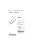
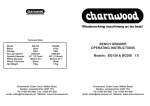
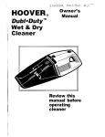
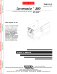
TELEFLEX MORSE Marine Products
Marine Ignition
Interrupt Switch
Part Numbers
311482-001 (For I/0s and Inboards)
311482-002 (For Outboards)
For Use With Teleflex Morse MV3 Side Mounted Controls
Installation Manual
INSTALLATION, OPERATION and
MAINTENANCE INSTRUCTIONS
This manual must be accessible to the owner/user of this
Teleflex Morse Marine Product
PLEASE READ THESE INSTRUCTIONS CAREFULLY
AND THOROUGHLY BEFORE INSTALLING OR OPERATING
THIS IGNITION INTERRUPT SYSTEM! YOU MUST HAVE
THE MV3 SIDE MOUNTED CONTROL INSTRUCTIONS AND
MOUNTING TEMPLATE WITH YOU TO PROPERLY INSTALL
THIS MARINE PRODUCT.
All specifications and features are subject to change without notice.
Page 1 of 4 Pages
055001-695 Rev. C 10/03 © 2003 Teleflex, Inc.
ë\
General Information
Installation
This Interrupt Switch is to be used solely with
Morse MV3 Side Mounted Controls to stop the
engine of an inboard, I/O or outboard powered
boat instantly in the event an operator is accidentally removed from the controls. The Interrupt
Switch includes a lanyard clip which holds the
plunger of the Switch in position to allow engine
operation. A lanyard extends from the clip and is
connected to the operator. Should the operator
move away from the controls the clip is pulled
free, releasing the plunger and stopping the
engine.
1.
F ig u r e 1 .
5 /8 "
D ia m e te r
S w itc h
M o u n tin g
H o le
Before drilling, check behind the panel for
sufficient clearance around wires, pipes,
control cables and other obstructions.
2. Remove control and drill a 5/8 inch diam
eter hole in the cover from the backside. A
drill point is molded in.
2A. You may use the 5/8 inch diameter hole that
you drilled in the control cover as a pilot hole
and drill a 1-1/8 inch hole in the mounting
panel.
2B. Add the ìWARNINGî label to the bottom
of the MV3 Face Plate. (See Figure 1.)
3. Insert the Interrupt Switch from behind the
mounting surface, through the MV3
Control.
4. Tighten the Flanged Nut to 40-50 inch
pounds to secure the Switch. Do not over
tighten.
5. Check for proper mounting security by
removing the lanyard assembly with a tug
on the cord. Re-tighten nut if the Switch is
loose.
Electrical Connections for I/O or Inboard Use
Only
In te r r u
o p e ra to r
o p e ra to
R e a d
p t
w h
r m
O
!
s w
ile
u s
w n
W A R N IN G
itc h
e n g
t b e
e r 's
m
in
in
M
u s t b e
e is r u n
c o n tro
a n u a l b
a tta c h e d
n in g .Q u a
l a t a ll tim
e fo re u s e
to
lifie d
e s .
.
1.
2.
Disconnect all batteries and any auxiliary
on-board or dockside power supplies.
Locate the purple ignition switch-to-coil wire.
See Diagram A.
F ig u r e 2 .
B e S u r e M o u n tin g A r e a
is S o u n d a n d S e c u r e .
BE SURE THIS WIRE GOES DIRECTLY TO
THE COIL AND NOT TO THE INSTRUMENT OR ALTERNATOR CIRCUIT.
SELECTING THE INCORRECT WIRE WILL
RESULT IN IMPROPER SWITCH OPERATION WHICH COULD LEAD TO SERIOUS
lNJURY.
M o u n tin g
P a n e l
3.
T e r m in a ls
P lu n g e r
4.
5.
F la n g e d N u t.
T ig h te n 4 0 -5 0
in c h p o u n d s
Cut the Purple wire, strip the ends and
install two (2) insulated crimp-on 1/4 inch
female disconnect terminals. A crimping tool
designed for insulated terminals MUST be
used.
Attach the female disconnects to each of
the male terminals on the Interrupt Switch.
Recheck all connections. Install Lanyard
with the Fork Clip seated on the Plunger.
055001-695 Rev. C 10/03 © 2003 Teleflex, Inc.
Page 2 of 4 Pages
D ia g r a m
A . I/O
a n d In b o a r d W ir in g
Table 1.
Wire Color Table
For Late Model Outboards
C lip M u s t b e In s ta lle d fo r
P r o p e r O p e r a tio n .
S w itc h
P /N 3 1 1 3 7 5 -1
Ig n itio n
s w itc h
P u r p le
Y e llo w /R e d
P u r p le
T o S ta rte r
P u r p le
R e d
M a in P o w e r
T o
In s tr u m e n ts
T o
A lte r n a to r s
In s u la te d 1 /4 in c h
fe m a le b la d e
d is c o n n e c t
6.
7.
8.
Daihatsu
Evinrude
L a n y a rd
P u r p le
W h ite o r
b la c k
Force
Johnson
S y s te m
g ro u n d
Mariner
Mercury
Nissan
OMC
Ig n itio n c o il
o r C D u n it
Reconnect battery.
Start engine. If engine does not start:
Disconnect battery, recheck all electrical
connections, reconnect battery and restart
engine.
Remove Lanyard. Engine should stop
immediately.
IF ENGINE FAILS TO STOP, RECHECK
ALL WIRING. SHOULD THE ENGINE
FAIL TO START OR STOP, OR RESUMES
RUNNING WITH THE LANYARD FORK
REMOVED, CONSULT YOUR LOCAL
MARINE DEALER FOR ASSISTANCE.
Suzuki
USMarine
Yamaha
4.
5.
6.
7.
Electrical Connections for Outboard Use
Only
THIS INTERRUPT SWITCH IS
DESIGNED FOR USE WITH
OUTBOARD MOTORS EQUIPPED WITH
GROUNDING TYPE EMERGENCY
STOP CIRCUITS ONLY!
Measure and cut two lengths of Black 16
AWG marine quality wire of sufficient
length to connect one Interrupt Switch
terminal to the Emergency Stop Wire and
the other terminal to a System Ground.
See Diagram B.
Strip one end of each wire and crimp on
an insulated 1/4 inch female disconnect
terminal. A crimping tool designed for
insulated terminals MUST be used.
Attach the female disconnects to each of
the male terminals on the Interrupt Switch.
Attach the other end of one wire to the
Emergency Stop Wire, using a suitable
insulated wire connecting device,
reference Wire Color Table and
Diagram B.
D ia g r a m
B . O u tb o a r d W ir in g
C lip M u s t b e In s ta lle d fo r
P r o p e r O p e r a tio n .
M a g n e to
If the following information is not correct for your
model motor or application, consult your local
marine dealer for details.
1. Disconnect all batteries and any auxiliary
on-board or dockside power supplies.
2. Remove Engine Cover.
3 Locate the correct color emergency stop
wire for your motor (reference Table 1).
Page 3 of 4 Pages
Solid Brown
Black with Yellow Stripe
Before 1969. Solid Blue
Solid White
Black with Yellow Stripe
Before 1969, Solid Blue
Black with Yellow Stripe
Black with Yellow Stripe
Solid Brown
Black with Yellow Stripe
Before 1969, Solid Blue
Solid Brown
Blue with Black Stripe or Solid Blue
Black with Yellow Stripe
S e e c o lo r
ta b le
T e r m in a te to
m a tc h e m e rg e n c y
s to p w ir e e n d
B la c k
E m e rg e n c y
s to p w ir e
te r m in a tio n
E m e rg e n c y
s to p w ir e
055001-695 Rev. C 10/03 © 2003 Teleflex, Inc.
L a n y a rd
B la c k
In s u la te d 1 /4 in c h
fe m a le b la d e
d is c o n n e c t
N e w w ir e n o t in c lu d e d .
R e c o m m e n d 1 6 A W G .
S e e in s ta lla tio n n o te s
S w itc h
P /N 3 1 1 3 7 5 -2
T e r m in a te
to s u it
E n g in e
g ro u n d
8.
9.
10.
11.
12.
13.
Attach the other end of the second wire to
the ground point, using a suitable
insulated wire connection device as
shown in Diagram B.
Recheck all connections. Install the
Lanyard with the Fork Clip seated over the
Plunger.
Replace engine cover.
Reconnect battery.
Start engine. If engine does not start:
Disconnect battery, remove engine cover,
recheck all electrical connections, replace
cover and restart engine..
Remove Lanyard. Engine should stop
immediately.
IF ENGINE FAILS TO STOP, RECHECK
ALL WIRING. SHOULD THE ENGINE
FAIL TO START OR STOP, OR
RESUMES RUNNING WITH THE
LANYARD FORK REMOVED, CONSULT
YOUR LOCAL MARINE DEALER FOR
ASSISTANCE.
Installation Notes
ALL WIRING. CONNECTIONS AND TERMINATIONS should be done in accordance with ABYC
Spec. E-9-90.
Use 16 AWG Purple stranded insulated marine
quality wire for I/0 or Inboard applications. (Type
HDT, THW, UL 1426 or equivalent.)
Use 16 AWG Black stranded insulated marine
quality wire for all outboard applications. (Type
HDT, THW, UL 1426 or equivalent.)
Operating Instructions
1. Before each motor start. check that the
Lanyard Fork Clip is properly seated over the
switch and rotates freely. Inspect the Lanyard.
If it is cut. worn or frayed. it must be replaced.
F ig u r e 3 .
P lu n g e r
L a n y a rd
S n a p
H o o k
L a n y a rd
fo r k c lip
2. The Lanyard Snap Hook should be securely
attached to the operatorís body. Do not attach
the Hook to a belt loop or button hole as these
lack the strength to assure proper Switch
operation.
3. Start the engine.
4. Test the Switch by pulling the Lanyard Fork
Clip free from the Switch.
IF ENGINE FAILS TO STOP, RECHECK ALL
WIRING. SHOULD THE ENGINE FAIL TO
START OR STOP, OR RESUMES RUNNING
WITH THE LANYARD FORK REMOVED,
CONSULT YOUR LOCAL MARINE DEALER
FOR ASSISTANCE.
DO NOT USE ANOTHER
MANUFACTURERíS LANYARD ON THIS
INTERRUPT SWITCH, OR CHANGE THE
LENGTH OF THE LANYARD AS THIS MAY
AFFECT SWITCH OPERATION.
6980 Professional Parkway East
Sarasota, FL 34240
(941) 907-1000
FAX (941) 907-1020
MISUSE, MISAPPLICATION,
UNAUTHORIZED MODIFICATIONS, OR
INCORRECT INSTALLATION OF THIS
SAFETY DEVICE COULD RESULT IN
SERIOUS BODILY INJURY OR DEATH.
055001-695 Rev. C 10/03 © 2003 Teleflex, Inc.
Page 4 of 4 Pages