1
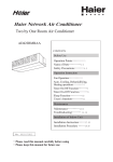
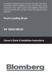
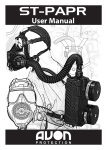
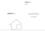
Free Combination Multi-split Type
Room Air Conditioner
AE122BCAAA
(H2EM-18H03)
Contents
Before Use
Operation Points--------------------------1
Name of Parts ----------------------2-3
Safety Precautions---------------------4-5
Operation Instruction
Fan Operation-----------------------------6
Auto, Cooling, Dehumidifying,
Heating Operation---------------------7
Timer On/Off Function---------------8
Timer On-Off Function --------------9
Sleep Function-----------------------10
User's Attentions---------------------11
Maintenace
Maintenance--------------------------12
Troubleshooting----------------------13
Installation of Indoor Unit
Installation Instruction----------14-16
No. 0010572805
Please read this manual carefully before
using
Please keep this manual for future use
Installation Procedure ----------17-26
Operation points
Operation of air conditioner
When the ambient humidity is too high, in
COOLING or DEHUMIDIFYING mode,
there may be water dropped in the air outlet.
Anti-cold air blowing out
During Heating operation, after starting
the unit, the indoor fan motor will not
rotate immediately to prevent cold air from
blowing out.
Please wait
?
3-minute protection function
If start the unit immediately only after it is
turned off, the compressor will start after 3
minutes have elapsed to protect the compressor.
Change of fan speed
In COOLING mode, the air sending is set at AUTO, when the
indoor temperature is near the set temperature, the fan speed
will lower automatically. In HEATING mode, when room
temperature reaches the set temperature, the compressor will
stop running, and the fan will change to LOW FAN or stop.
In DEHUMIDIFYING mode, the fan speed will change
automatically.
Defrosting function
During Heating operation, when frost formed
on the heat exchanger of outdoor unit, the
air conditioner will de frost
automatically for several
minutes. During defrosting,
both the fan of indoor and
outdoor unit do not run. After
finishing defrosting, the air
conditioner will automatically
resume operation.
Hint
When the air conditioner is in Heating mode,
it absorbs heat from outside and release to
indoors. So the outdoor temperature may
affect the Heating effect.
Power failure resume function (please set and use this function according to actual condition)
After setting power failure resume function, if there is a sudden power failure during unit
operation, when power on for again, the unit will resume the previous state.
Setting method: when the wire controller is in ON state (except for TIMER and FAN mode),
press the SLEEP button for 10 times in 5 seconds, after the buzzer sounds 4 times, the unit will
change to POWER FAILURE RESUME function.
Cancellation method: press the SLEEP button 10 times in 5 seconds, after the buzzer 2 times, the
POWER FAILURE RESUME function is cancelled.
Note: After the unit is set POWER FAILURE RESUME function, if there is a sudden power
failure in using, during this period of time if there is no need to use the unit for a long time,
please cut off power to prevent the air conditioner from automatically resuming to the
previous setting if power failure resumes, or press the ON/OFF button to turn off the unit
after power failure resumes.
1
Name of Parts
Indoor unit
Motor
Fan
Electric box
Air outlet grille
Evaporator
Drain pan
Wire controller
Mode Fan Speed
AUTO
Swing
Temperature
**
Clock
Set
Timer
Sleep
**
Aux. Heat Fileter Reset
Reset
ON/OFF
2
Safety Precautions
Before starting the unit, please read the following ìSafety Precautionsî carefully to guarantee the normal
operation of the system.
The following lists two kinds of safety precautions ìWarningî and ìNoticeî. For the items that the improper
use may cause death or serious injury are listed in ìWarningî volume. However, sometimes the items listed
in ìNoticeî volume may also cause serious accidents. So, these two volumes are the important contents
related to safety, they must be observed.
Do equip with
Do follow the
Do not do like this
grounding wire
instruction
After carefully reading this manual, please keep in hand for reference. If the air conditioner is given to a new user,
this manual should be attached with unit to the new user.
Installation Safety Precautions
Warning
The system should be applied to
places as office, restaurant,
residence and the like.
The system should be installed by your
dealer or a professional installer.
Application to inferior environment
such as workshop, it may cause
equipment malfunction and serious
injury or death.
Installation by yourself is not encouraged.
Because improper installation could cause
water leakage, electric shock and fire
accident.
Notice
A creepage breaker must be
installed at the installation place
Drain pipe should be arranged
properly to provide a smooth
drainage.
Make sure the system is grounded.
ON
OFF
Unless the circuit breaker is
installed, it may cause
electric shock.
If the pipe is arranged improperly,
furniture or the like may be
damaged by the leaked water.
Grounding wire should never be
connected to gas pipe, city water
pipe, lightning conductor rod or
the telephone line. If the grounding
wire is not set properly, it may cause
Operation safety precautions
Warning
Do not let the cold wind blow to
human body for a long time.
When any abnormal condition (scorching
smell or others) is found, stop operation
immediately and turn off the power switch.
Then consult your dealer.
It may affect the physical condition
or cause some health problems.
If continuing the operation without removing the
cause, it may cause trouble, electric shock or fire.
Notice
4
Do not handle switches with a wet hand.
Do not use water to clean the air conditioner.
It may cause electric shock.
It may cause electric shock.
Safety Precautions
Notice
The system should never be used for
any other purposes than intended such
as for preservation of food, flora and
fauna, precision devices or work of
art.
Do not put or use any spray
near the air conditioner, and
do not directly spray to the
air conditioner.
Do not put the fire devices in
the places, which the air from
the air conditioner can directly
blow.
Otherwise it may cause It may cause the fire devices
It may cause deterioration of the articles. fire.
cannot burn completely.
Do not install the system where the air
Only use the proper specified fuse.
outlet may directly reach the flora and fauna.
If use metal wire
or copper wire to replace the fuse, it
It will not be good for their health.
may cause trouble and fire accident.
Do not use the power When operating the system When cleaning, please
switch to turn of or off the simultaneously with a combustion stop the unit and cut off
air conditioner.
the power first.
apparatus, indoor air must be ventilated
frequently.
Do not perform
cleaning, when the
Insufficient ventilation may cause
indoor fan motor is
It may cause fire
the danger of lack of oxygen.
rotating in high speed.
or Creepage.
Do not put the water
Do not use such equipment as
containers, such
awater heater, etc., around the
as vase, on
indoor unit or the
the unit.
wire controller.
If
If the system is operated at the vicinity of such the water enters into the unit
equipment that generates steam, condensed water may and damages the electric
drip during cooling operation or it may cause Creepage insulation material,it may
cause electric shock.
or short-circuit.
ON
OFF
Safety precautions when moving, reinstalling and repairing the air conditioner
Warning
Do not refit the air conditioner. When repair When moving the air conditioner to another
installation place, please contact the dealer
is needed, please contact your dealer.
or the professional installer.
Improper moving and reinstallation may
Improper repair may cause water leakage, cause water leakage, electric shock and
electric shock and fire accident.
fire accident.
5
Operation instruction
1
2
Mode Fan Speed Swing
Temperature
3
Clock
Set
Timer
Sleep
2
Fan operation
Turn on the unit
Press the ON/OFF button to turn on the
unit The LCD display of the wire
controller will show the previous
working state (except for Timer, Sleep,
Swing mode), the operation indicator
light on the wire controller will light up.
Choose of working mode
Press MODE button, each press the working
mode will change as the following sequence:
AUTO COOLING DEHUMIDIFYING
HEATING FAN,
Aux.HeatFileter Reset
Reset
4
ON/OFF
1
AUTO COOLING DEHUMIDIFYING HEATING FAN
Choose FAN operation.
3
Adjusting FAN SPEED
Press the FAN SPEED button to change fan
speed:
LOW FAN
MED FAN
HIGH FAN
LOW FAN MED FAN HIGH FAN
Choose the desired fan speed
4
Turn off the unit
Press the ON/OFF button to turn off the unit.
The wire controller only shows the clock and
room temperature.
About FAN operation
FAN operation refers the air conditioner does not perform COOLING and HEATING
operation, but FAN operation. In this mode, the air conditioner cannot perform
AUOT FAN operation, and does show the temperature value on the wire controller.
6
then choose AUTO, COOLING, DEHUMID
IFYING, HEATING operation.
Operation instruction
Timer On/Off function
Before using TIMER function, calibrate the clock first (referring to page 3). When you wake up in
the morning, before going back to home after work or after going to bed, you can let your air conditioner
automatically turn on or turn off.
1. Turn on the unit
Mode Fan Speed Swing
2. Set of TIMER mode
Temperature
**
After turning on the unit, set the desired working mode.
The LCD of the wire controller will show working mode.
(except for Timer, Sleep, Swing)
Clock
Set
Timer
Sleep
Aux.Heat Fileter Reset
Reset
Press the TIMER button to change the TIMER mode,
each press the TIMER mode will change as the following
sequence:
ON
AM
ON/OFF
3. Set time
OFF
PM
Timer On Timer Off
ON
AM
OFF
Blank
PM
Timer On-Off
Then choose the timer mode as you need
(TIMER ON or TIMER OFF.)
At this time the ON or OFF will flash.
Press the time adjusting button
Each press, the set time increases 10 minutes. If depress the button, the time will increase
rapidly.
Each press, the set time decreases 10 minutes. If depress the button, the time will decrease rapidly.
This LCD will show the time set, the time can be adjusted within 24h.
(AM stands for morning, PM stands for afternoon).
4. Confirm the time
After calibration of the clock, press SET button to confirm time.
At this time, the ON or OFF will not flash.
The time displayed is: at x oíclock x minutes the unit will be turned on
(TIMER ON) or turned off (TIMER OFF).
Cancel TIMER
Press the TIMER button several times until the TIMER mode display
disappears.
Hints:.
After power failure, the clock should be calibrated again.
The wire controller has memory function, when you use this function
for the second time, if the time set is the same as the previous one, you
just need to choose the TIMER mode then press the SET button to confirm.
Operation instruction
Timer On-Off function
1. After turning on the unit,
set the proper working mode
**
**
The LCD of the wire controller
will show working mode.
(except for Timer, Sleep, Swing)
**
**
**
**
**
**
**
**
****
2. Set of TIMER mode
6
5 **
Press the TIMER button to change the TIMER
mode, each press the TIMER mode will change
as the following sequence:
ON
AM
OFF
PM
ON
AM
OFF
PM
**/**
Then choose the TIMER ON-OFF mode.
At this time the ON will flash.
3. Set the TIMER ON time
Press the time adjusting button
Each press, the set time increases 10 minutes. If depress the button,
the time will increase rapidly.
Each press, the set time decreases 10 minutes. If depress the button,
the time will decrease rapidly.
The LCD shows the time set.
It can be adjusted arbitrarily in 24 hours. (AM refers to morning,
4. Confirm the time
After adjusting time, press SET button to confirm time.
At this time, the ON will not flash, OFF begins to flash.
The time displayed is: at x oíclock x minutes the unit will be turned
5. Set the TIMER OFF time
Press the TIME button, the adjustment method is the same as
the one of setting TIMER ON time.
6. Confirm the time of TIMER OFF
After adjusting time, press SET button to confirm time.
At this time, the OFF will not flash.
The time displayed is: at x oíclock x minutes the unit
will be turned off.
Cancel TIMER
Press the TIMER button several times until the TIMER mode display disappears.
According to the sequence of TIMER ON & TIMER OFF setting, you can realize
turning on unit first, then turning off unit.
9
Operation instruction
Sleep operation
Before going to bed, you can press the SLEEP button, the air conditioner will operate
in comfort sleep mode to make you have a sound sleep.
Before using this function, you should calibrate the clock first, otherwise, the SLEEP
function will be out of order.
Use of SLEEP function
After turning on the unit, setting the working mode, then press SLEEP button to
make the air conditioner have the previous Sleep time (powered on for the first
time or after performing Sleep is 1h). The Sleep symbol will appear. Press time
/ button, you can choose between 1~8h. Each press, it may increase/decrease
1h and will display in the humidity area with ìxhî, and display ìTimer Offî in
Timer Off area and the time to turn off; press Sleep button again to cancel Sleep
Operation modes
about 6 hours
1.In COOLING, DEHUMIDIFYING operation
1 hour later in SLEEP operation, the temperature
will increase 1C from the set temperature, another
1 hour later increase another 1C, then the unit
will operate continuous for 6 hours, then it turns
off automatically. The temperature is higher than
set temperature to prevent you from getting a cold.
Increase 1*
1hour
1hour
Increase 1*
Set temperature
turn off
In COOLING and DEHUMIDIFYING operation
Set temperature
2.In HEATING operation
1 hour later in SLEEP operation, the temperature
will decrease 2C from the set temperature, another
1 hour later increase another 2C, then the unit
will operate continuous at this temperature for 3
hours, then it increases 1C, after operating at this
temperature for another 3 hours, the unit
will turn off automatically. The temperature is
lower than set temperature to prevent you from
feeling uncomfortable during sleep.
SLEEP operation stops
SLEEP operation starts
1hour
turn off
Decrease2*
1hour
Decrease2*
About 3 hours
3 hours
In HEATING operation
Mode Fan Speed Swing
Temperature
3.In AUTO operation
Set
The air conditioner will operate in the relative Sleep
operation according to the operation mode.
Increase 1*
SLEEP operation stops
SLEEP operation starts
Clock
Set
Timer
Sleep
Aux.HeatFileter Reset
Reset
ON/OFF
4.In FAN operation
SLEEP operation cannot be applied.
Note:
After setting Sleep function, it is not permitted to adjust clock.
The Sleep time is less than 8h, after reaching the set time, the unit will automatically stop.
Set Sleep function after setting ìTimer Offî function, the air conditioner will perform Sleep function.
After setting Sleep function, the Timer function cannot be set.
Set Sleep function after setting ìTimer Onî function, the Sleep function can only be set in the set time
of Timer On.
10
Usersí Attention
Do not press tightly with the LCD part of
the wire controller to avoid damage of it.
Set proper room temperature
Not too low or high and make every
people in the room feel comfortable.
Cooling
26-28 *
Heating
18-23*
Do not let the cold air blows
directly to human
body for a long time
and do not make the
room temperature
Otherwise, it may cause
uncomfortable or bad to your health.
The room should
often ventilate.
After a long-time
of using air
conditioner, the
room must be ventilated.
As the character of Heat Pump air
conditioner, the heating capacity will
decrease with the outside temperature drops.
Do not keep the doors and
windows open
Otherwise, it may lower the
efficiency of the air conditioner.
Television, radio and acoustics, etc.
equipment should keep
over 1m from indoor
unit and wire controller.
Otherwise, they may
disturb the image and cause noise.
In actual installation, because of the
influence of neighboring noise and
reflection, the noise of the unit
generally will be higher than the
written value.
Do not put any heating devices under
the indoor unit.
The heat may cause the
deformation of indoor unit.
If do not use the air conditioner for a
long time, it is necessary to cut off
power.If do not cut off power, the unit
may consume power. In order to protect
the unit, before using
the air conditioner
Cut off
again, turning on
power
the power at least
12 hours in advance.
The windows should be hung with
curtains or blinds.
Do not let the sun
shine directly shine
in the room; do not
let the outdoor air enter room.
The articles must keep dry cannot
be put under the
indoor unit.
When the humidity is
over 80% or the drainage
outlet is blocked, the
Do not put articles around the air
inlet and outlet.
This kind of obstacle
can lower the efficiency
of the air conditioner
In actual use, the difference of
outdoor temperature, room size,
room structure and direction will
make the capacity and power
consumption change of the unit.
The airflow cannot
directly blow to the pets
and plants.Otherwise,
the petsand plants
will be harmed
The air conditioner can only be
used in air conditioning. It can
not be used in other purpose.
Do not use the air conditioner in
some specific purpose,
such as storage or prot
ect food, animals,
plants, precise
instrument and
artwork, otherwise,
the quality of them may be declined.
11
Maintenance
When maintaining, do turn off the manual power switch.
Daily cleaning
Clean air conditioner and wire controller
Use soft cloth to dry clean
If there is too much dirt on the air conditioner panel,
please soak the cloth with water, and then clean it.
(The wire controller cannot use water to clean, it
should use dry cloth to clean.)
It is forbidden to use gasoline, diluent, eradicator
powder and chemical dishcloth etc. to clean,
otherwise it may cause deformation and crack.
Maintenance after the using season
In a sunny day and FAN mode, let the unit operate about half a day to make
the inner part of the unit dry.
Turn off the operation switch of the air conditioner, cut off the power switch.
Otherwise, even the air conditioner is in OFF state, it will consume certain
power.
Clean the air filer and the system of indoor unit, wash and clean the outdoor
unit, and use dustcoat to cover the unit.
Maintenance before the using season
Check if there are any obstacles in the air inlet and outlet
of indoor and outdoor unit to avoid the working
efficiency drop.
Please do install the air filter and insure it is not dirty.
Please check first
Otherwise, the unit is damaged or has trouble due to
the dust entry into the unit.
In heating, in order to protect the compressor in starting the unit, please switch
on the power switch of the unit 12 hours in advance before using it, and in
using season, please always keep the power switch in ON state.
12
Troubleshooting
Before as the special repair center for help, please check the following items of the air
conditioner
Not trouble
Symptom
Cause
Hear the sound of
water flow
The water flow sound when operation starts; during operation and shortly
after operation stops, in 2-3 minutes shortly after the operation starts,
sometimes the sound becomes louder. This is the sound of refrigerant flow
and the draining sound of condensate water.
In DEHUMIDIFYING,
no air sent out or cannot
change the fan speed.
In DEHUMIDIFYING operation, when the room temperature is 2 C higher
than the set temperature, despite of the set FAN SPEED the air conditioner
will operate in LOW FAN SPEED.
Having peculiar smell
in the out air
Because the smells generated by wall, carpet, furniture,clothes, cigarette
and cosmetic, etc. attached on the air conditioner.
The stopped indoor unit
gives out sound, white
vapor or cold air.
In order to prevent the oil and refrigerant from resorting in the indoor
unit, there is refrigerant flow in very short time, so they give out ìSha,
Shaî, ìGulu, Guluî. Additionally, when the other indoor units perform
HEATING operation, sometimes white vapor appears; when the other
indoor units perform COOLING operation, cold air appears.
If there is the following symptom and check they are the following causes,
please solve them according to the below given methods.
Symptom
The unit does
not work
Once the unit starts,
it stops immediately
Abnormal
COOLING or
HEATING
Causes
The fuse is blown out or the
breaker is open-circuit.
The air inlet or outlet of indoor and
outdoor unit is blocked
The air inlet or outlet of indoor
and outdoor unit is blocked
Improper set temperature
The fan speed is set too low
Doors or windows are open
Solution
Change fuse or close breaker
Remove the obstacle
Remove the obstacle
Refer to page 7
Refer to page 7
Close them
Direct sunshine. (COOLING)
Too much people in room (COOLING)
Too many heat sources in room (COOLING)
Hang curtains or blinds before window
Trouble Contents
Code Displayed
Indoor temperature sensor trouble
F1
Inner pipe coil sensor trouble (thin pipe)
F2
Inner pipe coil sensor trouble (thick pipe)
F4
High pressure trouble (pressure)
F5
F6
Drainage trouble
If after the above checking and treatment, the air conditioner still cannot work normally, or
find the following phenomena, please stop the unit and contact the commissioned service
center.
The fuse or breaker is often blown out or open circuit.
In COOLING or DEHUMIDIFYING, there is water leakage.
Abnormal operation or abnormal sound be heard.
The display screen of the wire controller shows trouble code indicating the unit has
trouble.
13
When Troubles Occur
Before installing, do read this ìSafety precautionsî carefully to guarantee theproper installation.
The below attentive matters are divided into ì Warningî and ì Noteî two parts. When the wrong
installation occur, it is very possible death and severe injury and other serious accidents will happen.
For those items are listed in ì Warningî part. But even the items listed in ì Noteî part can also
cause serious accidents. Above all,both the two parts are very important contents related to safety,
so they must be obeyed.
After finishing the installation work, do test run to verify everything is normal. After that please explain
the using and maintenance methods to the user. Additionally, give this installation manual and operation
manual to the user and ask them to keep it properly.
Warning
The commissioned repair center shall do the installation work. If you do the installation work by
yourself, the improper installation will cause water leakage, electric shock fire and other accidents.
The installation work shall be in line with what the installation manual specified. If installation is not
proper, water leakage, electric shock, fire and other accidents will occur.
Install the air conditioner to a place where can definitely stand its weight. The air conditioner can
not be installed on a nonmetal bracket (such as theft guard net). Places not firm enough will cause
drop down of unit resulting in body hurt.
The installation work shall be preventive to typhoon and earthquake. If the installation work is
not met with the requirements, overturn of the unit will occur resulting in accidents.
Using the specified cable to do wiring work and connecting firmly and properly. Fix the connecting
part of the terminals to prevent it from the external force. Improper connection and fixing will cause
heating and fire etc. accidents.
Wiring shall be kept in correct shape avoiding extrusion. After installation, the electric box cover and
the external panel shall not nip the wire. Improper installation will cause heating and fire etc. accidents.
When setting or moving the air conditioner do not let the air and things alike get into the refrigeration
system except the specified refrigerant (R22). If air and other things enter, abnormal high pressure
will occur, which easily cause break and body injuries etc. accidents.
When installing, do use the accessories or specified parts. If not using the parts specified
by our company, water leakage, electric shock, fire and refrigerant leakage will occur.
Do not lead the drain hose to drain where the sulfur gas may be involved. Otherwise,
the poisonous gas will enter into the indoor.
During installation, if refrigerant leakage occurs, do the ventilation work immediately.
As soon as the refrigerant gas meets fire, poisonous gas will be produce.
After installation, confirm there is no leakage of refrigerant. If the refrigerant gas enters into room
and meet the air blowing heater, heater or stove etc. fire source, the poisonous gas may be produced.
Do not install the unit in a place where the combustible gas may be leaked. In any case
the combustible gas leaks and accumulated around the unit, fire accident will occur.
The drain hose should be correctly installed according to the installation manual to ensure
smooth drainage, and take proper heat preservation measure to prevent from dew.
Improper pipe installation may cause water leakage result in wet the indoor articles.
Do heat insulation work to the refrigerant gas pipes and liquid pipes to reach the purpose of heat
preservation. If the heat insulation measure is not sufficient, water generated by condensing dew will
drip leading to wet the floor and indoor articles.
Notice
14
Do grounding work. Do not connect the grounding wire to gas pipe, tap, lighting rod or
telephone line. Improper grounding will cause electric shock.
In some places the creepage breaker shall be installed. If do not install the breaker, electric
shock may occur.
After electric installation, power on them to do electric leakage test.
Installation instruction
Notice
This manual can not include all kinds of conditions, if you have new
requirements and questions, please contact with local Haier Sales Center.
Warning
Before installing the unit, please read this manual carefully. Improper installati
on may cause accidents and make unit damage or death.
Installation tools
1. Screwdriver
3. 60mm 70mm diameter drill
5. Spanner (14, 17, 19, 27mm)
7. Pipe flarer
9. Pincers
11. Tape measure
2. Steel saw
4. Spanner (diameter 17,27mm)
6. Pipe cutter
8. Knife
10. Leakage detector/soap water
12. Scraper
Standard accessories
The following parts mentioned in this manual are self-provided installation parts.
A
Mark
B
C
D
E
F
Nonbibulous
Connection
Name Adhesive Pipe
Drain hose thermal insulation Plaster
supportin pipe
of parts tape
powder
material
g plate
Accessories attached with the unit
The following lists the accessories attached with the unit, please use them according
to the installation needs.
NO.
Shape
&
name
2
1
Wire controller Signal wire
**
AUTO
**
3
Gasket
4
5
6
Thermal
Wire clamp insulation pipe Manual
**
**
**
**
**
**
**
**
**
****
**
**/**
Amount
1
1
8
*
2
1
15
Installation instruction
1. Installation of Duct
1)Duct material
Nonmetal
material
Thin metal sheet
Type
Material
Normal thin steel
Structural characteristic
Main use
Good processing performance and structural hardness
Galvanize steel
Aluminum orits alloy
Good anticorrosive performance
Stainless steel
Anticorrosive, acid-resistant
Aluminum foil soft
metal duct
Plastic compound steel
Soft with compression resistant, simple installation
with vibration resistance
Sprayed a layer of 0.2~0.4mm plastic on the normal
thin steel
Stiff PVC plastic
Anti-corrosive, glazed surface, easy production
Good processing performance, corrosion resistant,
uneasily sparkle
Generally used in ventilation duct system
Storm protection system in
ventilation engineering
Anti-corrosive ventilation
engineering in chemical industry
Widely used
Air conditioning system needing
good dust protection and anticorrosive system under 10~70*
Applicable to the ambient condition
of 0*60 *,ventilation system
with corrosion of acid gas
Anti-corrosive, glazed surface, easy
Glass fibre reinforced With light, high intensity, noncombustible,
anti-corrosive, high temperature resistant characteristic production
plastic
2) Sectional shape of duct (mainly has rounded and rectangular two shapes)
a
Rectangular duct
Rounded duct
d
b
a
b
R=2.5d
R*3/2b
3) Connecting mode
The dimension of rectangular duct is the same as the air outlet of indoor unit,can be directly connected; the rounded
duct needs to be added with a static pressure box to connect with the air sending outlet of indoor unit; independently
introduced to respective distributor by rounded duct. In order to meet the requirements of room air conditioner,
the fan speed in each air outlet of any distributor shall be adjusted to basically the same.
3
Air volume(m/h)
4) Installation parameter
Diameter of dut*mm)
Rectangular
H(mm)
L(mm)
duct
Out unit static pressure (Pa)
200
100
700
30
1-2
4
40/38/36
Number of duct outlet
Duct length (m)
Noise dB(A)
Recommended applicable area(m2) 14*25
Partial resistance of distributor(Pa) 25
Resistance along duct (Pa/m)
1.2
800*
*
*
*
Air volume-static pressure graph of duct type unit
600
*
*
*
*
*
*
*
*
*
*
*a
*
*
* b
*
*
400
Air volume-static pressure of duct type unit 0
5
10
15
20
* c
25
30
Static pressure
value(Pa)
Static pressure(Pa)
Air
3
Speed volume(m/h)
High speed
0
788
Medium speed 669
Low speed
543
16
5
10
15
20
25
30
763
642
519
740
615
480
716
587
463
687
567
442
663
538
418
632
512
390
Cutline
*
a
*
b
*
c
High speed
Medium speed
Low speed
Installation procedure
Install indoor unit
! Notice
Do not install the air conditioner at the place where
the combustible gas maybe leak. In case of the leaked
gas gather around the unit, it may cause fire accident.
The indoor unit should be installed in the place where the cool air and warm air may
evenly circulate.
Avoid the following places:
Place with too much salinity (coastal area).
Place with too much sulfuration gas (mainly is the hotspring area,
the copper pipe and brazed part are easily corroded).
Place with too much oil (including mechanical oil) and vapor.
Place using organic solvent.
Place with machines may generate high frequency electromagnetic waves.
(The control system may have abnormality)
Place near the doors or windows that come close to the external high humidity
air. (may easily form dew)
Place where the special sprayer may be frequently used.
On vehicles, boats and ships.
Place less than 1m away from TV, radio, radio devices and fluorescent lamp.
Indoor unit
1. Choose the place where the air from the air conditioner can spread
throughout the room and where the connection pipe, connection wire
and drain hose may be easily arranged to the suitable outdoor position.
2. Choose the place where the vertical distance between the center of air
outlet and the ground is no more than 2.7m.
3. The structure of the ceiling should be firm enough to bear the weight of the unit.
4. The connection pipe, drain hose and connection wire can penetrate
through the wall and connect indoor and outdoor unit.
5. The connection pipe and drain hose between indoor and outdoor unit
should be as short as possible.
6. The connection flare should be provided by user.
Safety precautions
1. For those models with electric heat function, it is forbidden to directly
connect the air outlet with canvas and material alike inflammable interfaces.
2. When installing indoor unit, it is necessary to leave a checking hole for
convenient repair.
17
Installation procedure
Install indoor unit
When install the duct hidden type indoor unit, the return air box must be
designed and installed, as Figure 1, Figure 2.
The distance between the air outlet of duct and the air outlet of air
conditioner should be no more than 1m (when the out unit static pressure is 0Pa).
Low static pressure duct type: max static pressure is 30Pa.
Building roof of installation
*1m
A
Ceiling
(Figure 1)
Air out duct
Unit
Return air box
Return air
Air supply
Air ourlet girlle
There should be
no obstacles
Air supply
Return air box
Unit
(Figure 2)
Return air
A amplified
M8 wide expansion screw bolt
M8 hoisting screw
Unit
(Figure 3)
M8 wide lock washer
M8 screw nut
B
B Rivet
Air supply passage
B amplified
C
C amplified
B
Use screw to
fix top panel
(Figure 4)
Top panel of unit
Air supply passage
Air supply passage
Air outlet grille
19
Installation procedure
Install indoor unit
Install the hoisting screw
Use M8 or M10 hoisting screw (4, prepare on site) (When the height of hoisting
screw is more than 0.9m, you must use M10), their gaps refer to the dimension
of air conditioner, according to the original structure and the following method
to install.
wood structure
Put up the frame wood on the beam and mount the hoisting screws.
Frame wood
Beam
Hoisting screw
New cement panel
Use embedded parts and foot screw, etc to mount.
Iron
Foot screw
(Knife type embedded part)
(Louver type embedded part)
(hoisting foot screw for connection pipe)
Original cement panel
Use the in hole hinge, in hole
plug or in hole screw.
Steel structure
Directly use angle steel or new angle
steel for support.
Suspending bolt
Hoisting screw
Suspending of indoor unit
Fix the cap of hoisting screw on and suspend them on the T groove
of the hoisting part of the unit.
Use gradienter to keep the level degree of the unit within 5mm.
20
Angle steel for support
Installation procedureInstall indoor unit
* Notice
In order to normally drain water, the drain hose should be mated according to the
installation manual. In order to avoid dew-forming, thermal insulation treatment
should be done.Improper connection pipe may cause water enter indoor.
Requirements:
The indoor side drain hose should be thermal insulated.
The parts connected with indoor unit should be thermal insulated. Improper
thermal insulation may cause dew-forming phenomenon.
The drain hose should be downwards slant (over 1/100) and there
should be no S-shaped bend. Otherwise, abnormal sound may occur.
The horizontal length of the drain hose should be less than 20m. If the
connection pipe is too long, the supporting frame should be set every
1.5~2m to prevent pipe from rise and fall.
For the centralized connection pipe, please perform work as the following Figure shown.
Pay attention not to exerting external force to the connection part of the drain hose.
1.5m*2m
Supporting frame
S-shaped bend
As large as possible (about 10cm)
Downward slant over 1/100
Thermal insulation material
user self-provided)
VP30
Downward slant over 1/100
wall
outside
Slant
Drain hose (user self-provided)
Material of connection pipe and thermal insulation
Material of connection pipe
Stiff PVC pipe VP 20mm (inside diameter)
Material of thermal insulation
Foam polyethylene pipe, thickness over 10mm
Confirm drainage
Perform test run to insure the condition of drainage, the connection part of the connection
should not leak water. The confirmation must be performed even if install in winter.
21
Installation procedure
Install indoor unit
! warning
During installation, if refrigerant leakage occurs, please immediately take ventilation measure.
If the refrigerant gas meet the fire, it may generate poisonous gas.
After finishing installation work, please make sure there is no refrigerant leakage. If the leaked
refrigerant gas meet heater and oven, etc. fire sources, it may generate poisonous gas.
Permitted length and fall of connecting pipe
Depending on the outdoor units, for details, please refer to the attahed manual of outdoor unit.
Material and dimension of connecting pipe
Material of connecting pipe
Dimension of connecting pipe
( mm )
Phospor deoxy copper seamless pipe used in air conditioner (TP2)
Gas side
12.7
Liquid side
6.35
Two spanners operation
Connection of refrigerant pipe
Perform connection of flared pipe to connect all the refrigerant pipes.
The connection of indoor unit connecting pipe must be performed by
two spanners.
For installation torque, please refer to the following table.
External diameter of
conneting pipe(mm)
22
Installation torque (N.m)
Tightening torque (N.m)
6.35
11.8(1.2kgf.m)
13.7(1.4kgf.m)
12.7
49.05(5.0kgf.m)
53.9(5.5kgf.m)
Installation procedure
Connection of pipe
1. Connection of pipe
Connection method
The connecting pipe max length of KRD-32N is 15m, and the max fall between indoor and outdoor unit is 5m;
the connnecting pipe max length of KDR-70N is 50m, the max fall between indoor and outdoor unit is 30m.
The max fall between two indoor units in one system is 10m.
Nut
Joint
In order to guarantee the efficiency, the pipe should be
Spanner
as short as possible.
Daub the refrigerant oil on the joint and the flared nut.
When bending the pipes, give the roundness as large
as possible, to avoid crashing the pipes.
Spanner
To connect the pipe, fit the center and use hand to screw
the nut, then use spanner to tighten the nut, as shown in figure.
Pay attention not to let alien matters, such as
If do not fit the center and screw the
sand, vapor get into the pipe.
nut hard, the screw thread may be
The connection of indoor unit pipe must be
damaged, which will cause
performed by using two spanners.
refrigerant leakage.
2.The additional charging amount of refrigerant
The additional charging of refrigerant (R22) should be complied with the installation manual
of outdoor unit. It must use measurer to quantificationally charge. The a dditional charging
amount must be complied with the specified amount.Requirements: Both excessive charging
and less charging of refrigerant will cause the compressor trouble. It must be complied with
the specified amount.
3. For discharging, please refer to outdoor unit
4.Leakage detection
Use leakage detector or soap water to check if the connected part of the
connection pipe and the valve cap leak.
5.Thermal insulation treatment
The thermal insulation of connection pipe should be performed at both gas side and
liquid side. In COOLING, both liquid side and gas side are in low temperature, in
order to prevent dew from forming, thermal insulation should be done.
The thermal insulation material at the gas side must use the material with the heat
resistant temperature over 120 C.
The connected part of indoor unit connection pipe should be thermal insulated.
The cut upward
Indoor unit
(Attached Figure)
On-site connection pipe side
Accessorial thermal insulation pipe
23
Installation procedure
Electric wiring
Note:
All the wires should be copper core wires.
The power cable of indoor unit should be equipped according to the operation manual of indoor unit.
Before finishing vacuumizing the refrigerant pipe system, do not supply power to indoor unit.
When connecting the indoor & outdoor wire, check the number of the indoor & outdoor terminals, the
terminals with the same number connected together with same one wire.
Incorrect wiring will damage the controller of the air conditioner or make the unit work abnormally.
The air conditioner must use special power circuit and special air switch (40A), groundign wire. The
wiring work should be done by a qualified electrician according to the national wiring rule.
The creepage breaker must be installed. The grounding line and the null line of the receptacle must be
strictly separated. It is incorrect to connect the null line with the grounding line.
The connection type of power cord is Y connection. If the soft power cord is damaged, to avoid risk,
it must be replaced by the manufacturer or their specific repair department or similar professional worker.
Wiring method
1.The wiring method of orbicular terminal
For the connection wire which end is orbicular
terminal, its wiring method is as the right figure
shown. Dismantle the screw and put it through the
ring at the end of the connection wire, then connect
it to the terminal block and tighten the screw.
The wiring method of orbicular terminal
Correct pressing
2.The wiring method of straight terminal
For those connection wires whose end are
not orbicular terminals, their wiring method
is:Loosen the connecting screw, insert the
end of the wire directly into theterminal
block, and then tighten screw. Pull the wire
outwards slightly to confirm it is held tightly.
Wrong pressing
Terminal block
Wire holding clamp
(Sketch map)
3.Pressing method of connection wire:
After wiring, the connection wire must be pressed with wire holding clamp. The
wire holding clamp should press on the out cover of the connection wire. As the
right figure shown:
The indoor and outdoor unit shall respectively use special power circuit.
The indoor units connected with the same outdoor unit, its creepage breaker and switch shall be
connected to the same power circuit.
The communication wire of indoor and outdoor unit is 2-core twisted-pair with polarity. (as right
figure shown)
The indoor and outdoor unit shall respectively use special power circuit.
1 2 3 4
P
Q
24
Outdoor unit 1PH, 220V~,50Hz
OK
P
P
Q
Q
P
Q
NO
Installation procedure Install wire controller
1. Remove the upper cover of wire controller
****
*****
The PC board is installed on the back cover of
wire controller. When remove the upper cover,
pay attention not to damage PC board.
**
*****
2. Install wire controller
Drill 2 wall holes according to the position of the 2 screw holes on the back cover of wire controller,
then hit wood in the wall holes. Put the 2 screw holes on the back cover of wire controller properly to
its corresponding wood, then use wood screws to fix the back cover on the wall.
Note:
Install the back cover of wire controller on the even wall as possible as can. When tightening
the wood screw, do not use to tight force, otherwise the wire controller may be damaged.
Switch
Mark ON
1
2
3
4
OFF
Inverter
Fixed frequency
Have rise and drop
Swing
The collection temperature
of main panel
No rise and drop
No Swing
The collection temperature
of panel
Under this series, the switch is set as:
1.ON 2. OFF 3. OFF 4.OFF
Dimension of signal wire:
Type of wire Shield wire (4 cords)
3. Indoor unit wire connection
Connect the terminals (A, B, C, D,) on the wire
controller to the terminals on the indoor PC panel
(A, B, C, D,) respectively.
Arrange wire from this part
AB
CD
Back cover
wire controller
Note:
When connecting wire, please keep
a certain distance between signal
wire and electric wire. (over
10mm)
Upper cover of
wire controller
Dimension
0.33 mm
2
The connection between indoor
unit and wire controller and
indoor unit and outdoor unit
should use shield wire. And the
two ends of the shield wire
should be grounded, otherwise,
the disturbance will cause unit
abnormal operation.
Shield wire
Grounded
Note:
Confirm the connection part of terminals is firm and will not touch shield wire.
4. Cover the wire controller upper cover
Pay attention not to press the connection wire.
Note: Do not touch PC board by hand.
25
Installation procedure Other instruction and test
Other instruction
Set of the air sending of the fan motor
Before leaving factory, the rotation speed of fan motor has already been set at standard choice.
When the indoor unit uses free air sending and not needing to connect with duct, the fan speed
of indoor unit is set at standard choice. When the indoor unit needs to connect with duct, please
according to the following figure shown to change the connection of the connector installed on
the side of electric box.
Standard air sending
(Before leaving factory)
Control box side
High fan speed air sending
The relative relation between
fan speed and static pressure
Control box side
Connector(White)
White
Connector(White)
Fan motor side
Fan motor side
Unit: Pa
Standard
fan speed
Red
High fan speed
0
30
Cut and flaring method
Use pipe cutter to cut the pipe, the
burrs must be removed.
After inserting the flarer,
perform flared nut.
A
Flarer
Connecting pipe Pipe diameter
Dimension A(mm)
Liquid pipe
6.35mm(1/4")
0.8~1.5
Gas pipe
12.7mm(1/2")
1.0~1.0
Incorrect
Correct
Slant
Broken
Burrs Uncompleted Too long
The following items must be noticed carefully during installation.
After finishing installation, performing checking.
After installing the refrigerant pipe, drain hose and electric wire properly,
perform test run to ensure the system not have trouble.
Test run
It is necessary the installer perform the test run for one time
to check if the unit works normally.
26