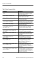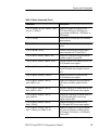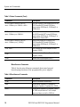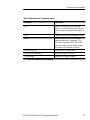
1
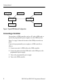
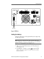
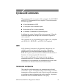
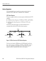
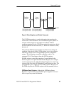
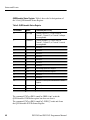
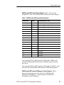
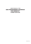
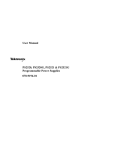
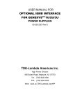
Programmer Manual
PS2520G & PS2521G
Programmable Power Supplies
070-9197-00
Copyright Tektronix, Inc. 1995. All rights reserved.
Tektronix products are covered by U.S. and foreign patents, issued and
pending. Information in this publication supercedes that in all previously
published material. Specifications and price change privileges reserved.
Printed in the U.S.A.
Tektronix, Inc., P.O. Box 1000, Wilsonville, OR 97070–1000
TEKTRONIX and TEK are registered trademarks of Tektronix, Inc.
WARRANTY
Tektronix warrants that this product will be free from defects in materials and
workmanship for a period of one (1) year from the date of shipment. If any such product
proves defective during this warranty period, Tektronix, at its option, either will repair the
defective product without charge for parts and labor, or will provide a replacement in
exchange for the defective product.
In order to obtain service under this warranty, Customer must notify Tektronix of the defect
before the expiration of the warranty period and make suitable arrangements for the
performance of service. Customer shall be responsible for packaging and shipping the
defective product to the service center designated by Tektronix, with shipping charges
prepaid. Tektronix shall pay for the return of the product to Customer if the shipment is to
a location within the country in which the Tektronix service center is located. Customer
shall be responsible for paying all shipping charges, duties, taxes, and any other charges for
products returned to any other locations.
This warranty shall not apply to any defect, failure or damage caused by improper use or
improper or inadequate maintenance and care. Tektronix shall not be obligated to furnish
service under this warranty a) to repair damage resulting from attempts by personnel other
than Tektronix representatives to install, repair or service the product; b) to repair damage
resulting from improper use or connection to incompatible equipment; or c) to service a
product that has been modified or integrated with other products when the effect of such
modification or integration increases the time or difficulty of servicing the product.
THIS WARRANTY IS GIVEN BY TEKTRONIX WITH RESPECT TO THIS
PRODUCT IN LIEU OF ANY OTHER WARRANTIES, EXPRESSED OR
IMPLIED. TEKTRONIX AND ITS VENDORS DISCLAIM ANY IMPLIED
WARRANTIES OF MERCHANTABILITY OR FITNESS FOR A PARTICULAR
PURPOSE. TEKTRONIX’ RESPONSIBILITY TO REPAIR OR REPLACE
DEFECTIVE PRODUCTS IS THE SOLE AND EXCLUSIVE REMEDY
PROVIDED TO THE CUSTOMER FOR BREACH OF THIS WARRANTY.
TEKTRONIX AND ITS VENDORS WILL NOT BE LIABLE FOR ANY
INDIRECT, SPECIAL, INCIDENTAL, OR CONSEQUENTIAL DAMAGES
IRRESPECTIVE OF WHETHER TEKTRONIX OR THE VENDOR HAS
ADVANCE NOTICE OF THE POSSIBILITY OF SUCH DAMAGES.
Table of Contents
Preface . . . . . . . . . . . . . . . . . . . . . . . . . . . . . . . . . . . . . . . . . . . .
v
Getting Started . . . . . . . . . . . . . . . . . . . . . . . . . . . . . . . . . . . . .
Setting Up the GPIB System . . . . . . . . . . . . . . . . . . . . . . . . . . .
Connecting a Controller . . . . . . . . . . . . . . . . . . . . . . . . . . . . . . .
Setting the Address . . . . . . . . . . . . . . . . . . . . . . . . . . . . . . . . . .
Testing the GPIB Connection . . . . . . . . . . . . . . . . . . . . . . . . . .
1
1
2
3
4
Syntax and Commands . . . . . . . . . . . . . . . . . . . . . . . . . . . . . .
SCPI . . . . . . . . . . . . . . . . . . . . . . . . . . . . . . . . . . . . . . . . . . . . . .
Commands and Queries . . . . . . . . . . . . . . . . . . . . . . . . . . . . . . .
Command Syntax . . . . . . . . . . . . . . . . . . . . . . . . . . . . . . . . . . . .
Command Header . . . . . . . . . . . . . . . . . . . . . . . . . . . . . . . .
Parameter . . . . . . . . . . . . . . . . . . . . . . . . . . . . . . . . . . . . . . .
Message Terminator and Message Separator . . . . . . . . . . . .
Entering Commands . . . . . . . . . . . . . . . . . . . . . . . . . . . . . . . . .
Command Characters . . . . . . . . . . . . . . . . . . . . . . . . . . . . . .
Abbreviating Commands . . . . . . . . . . . . . . . . . . . . . . . . . . .
Combining Commands . . . . . . . . . . . . . . . . . . . . . . . . . . . .
Summary of Commands . . . . . . . . . . . . . . . . . . . . . . . . . . . . . .
General Setting Commands . . . . . . . . . . . . . . . . . . . . . . . . .
Status Commands . . . . . . . . . . . . . . . . . . . . . . . . . . . . . . . . .
Miscellaneous Commands . . . . . . . . . . . . . . . . . . . . . . . . . .
5
5
5
6
6
7
9
9
9
10
10
12
12
13
16
Command Descriptions . . . . . . . . . . . . . . . . . . . . . . . . . . . . . .
*CLS (No Query Form) . . . . . . . . . . . . . . . . . . . . . . . . . . . . . . .
*ESE . . . . . . . . . . . . . . . . . . . . . . . . . . . . . . . . . . . . . . . . . . . . .
*ESR? (Query Only) . . . . . . . . . . . . . . . . . . . . . . . . . . . . . . . . .
*IDN? (Query Only) . . . . . . . . . . . . . . . . . . . . . . . . . . . . . . . . .
INSTrument:NSELect . . . . . . . . . . . . . . . . . . . . . . . . . . . . . . . .
INSTrument[:SELect] . . . . . . . . . . . . . . . . . . . . . . . . . . . . . . . .
INSTrument:COUPle:TRACking . . . . . . . . . . . . . . . . . . . . . . .
MEASure[:SCALar]:CURRent[:DC]? (Query Only) . . . . . . . .
MEASure[:SCALar]:VOLTage[:DC]? (Query Only) . . . . . . . .
*OPC . . . . . . . . . . . . . . . . . . . . . . . . . . . . . . . . . . . . . . . . . . . . .
OUTPut:PROTection:CLEar (No Query Form) . . . . . . . . . . . .
OUTPut[:STATe] . . . . . . . . . . . . . . . . . . . . . . . . . . . . . . . . . . . .
*RST (No Query Form) . . . . . . . . . . . . . . . . . . . . . . . . . . . . . . .
[SOURce:]CURRent[:LEVel][:IMMediate][:AMPLitude] . . . .
19
19
19
20
20
21
21
22
22
23
23
23
24
24
25
PS2520G and PS2521G Programmer Manual
i
Table of Contents
ii
[SOURce:]CURRent:PROTection:STATe . . . . . . . . . . . . . . . . .
[SOURce:]VOLTage[:LEVel][:IMMediate][:AMPLitude] . . . .
[SOURce:]VOLTage:PROTection[:LEVel] . . . . . . . . . . . . . . . .
*SRE . . . . . . . . . . . . . . . . . . . . . . . . . . . . . . . . . . . . . . . . . . . . .
STATus:OPERation:CONDition? (Query Only) . . . . . . . . . . . .
STATus:OPERation:ENABle . . . . . . . . . . . . . . . . . . . . . . . . . .
STATus:OPERation[:EVENt]? . . . . . . . . . . . . . . . . . . . . . . . . .
STATus:OPERation:INSTrument:CONDition? (Query Only) .
STATus:OPERation:INSTrument:ENABle . . . . . . . . . . . . . . . .
STATus:OPERation:INSTrument[:EVENt]? . . . . . . . . . . . . . . .
STATus:OPERation:INSTrument:ISUMmary<n>:CONDition?
(Query Only) . . . . . . . . . . . . . . . . . . . . . . . . . . . . . . . . . . . .
STATus:OPERation:INSTrument:ISUMmary<n>:ENABle . . .
STATus:OPERation:INSTrument:ISUMmary<n>[:EVENt]? . .
STATus:PRESet (No Query Form) . . . . . . . . . . . . . . . . . . . . . .
STATus:QUEue[:NEXT]? (Query Only) . . . . . . . . . . . . . . . . . .
STATus:QUEStionable:CONDition? (Query Only) . . . . . . . . .
STATus:QUEStionable:ENABle . . . . . . . . . . . . . . . . . . . . . . . .
STATus:QUEStionable[:EVENt]? . . . . . . . . . . . . . . . . . . . . . . .
STATus:QUEStionable:INSTrument:CONDition?
(Query Only) . . . . . . . . . . . . . . . . . . . . . . . . . . . . . . . . . . . .
STATus:QUEStionable:INSTrument:ENABle . . . . . . . . . . . . .
STATus:QUEStionable:INSTrument[:EVENt]? . . . . . . . . . . . .
STATus:QUEStionable:INSTrument:ISUMmary<n>
:CONDition? (Query Only) . . . . . . . . . . . . . . . . . . . . . . . . .
STATus:QUEStionable:INSTrument:ISUMmary<n>:ENABle
STATus:QUEStionable:INSTrument:ISUMmary<n>[:EVENt]?
*STB? (Query Only) . . . . . . . . . . . . . . . . . . . . . . . . . . . . . . . . .
SYSTem:AUTO . . . . . . . . . . . . . . . . . . . . . . . . . . . . . . . . . . . . .
SYSTem:ERRor? (Query Only) . . . . . . . . . . . . . . . . . . . . . . . .
SYSTem:VERSion? (Query Only) . . . . . . . . . . . . . . . . . . . . . .
*TST? (Query Only) . . . . . . . . . . . . . . . . . . . . . . . . . . . . . . . . .
*WAI (No Query Form) . . . . . . . . . . . . . . . . . . . . . . . . . . . . . . .
26
27
27
28
29
29
30
30
30
31
36
37
37
38
38
39
39
40
40
Status and Events . . . . . . . . . . . . . . . . . . . . . . . . . . . . . . . . . . .
System Structure . . . . . . . . . . . . . . . . . . . . . . . . . . . . . . . . . . . .
Status Registers . . . . . . . . . . . . . . . . . . . . . . . . . . . . . . . . . . . . .
SCPI Status Registers . . . . . . . . . . . . . . . . . . . . . . . . . . . . .
IEEE-488.1 and IEEE-488.2 Status Registers . . . . . . . . . . .
41
41
44
44
49
31
32
33
33
33
34
34
35
35
35
36
PS2520G and PS2521G Programmer Manual
Table of Contents
Enable Registers . . . . . . . . . . . . . . . . . . . . . . . . . . . . . . . . . . . .
Event Status Enable Register (ESER) . . . . . . . . . . . . . . . . .
Service Request Enable Register (SRER) . . . . . . . . . . . . . .
OPERation Enable Register . . . . . . . . . . . . . . . . . . . . . . . . .
QUEStionable Enable Register . . . . . . . . . . . . . . . . . . . . . .
Queues . . . . . . . . . . . . . . . . . . . . . . . . . . . . . . . . . . . . . . . . . . . .
Output Queue . . . . . . . . . . . . . . . . . . . . . . . . . . . . . . . . . . . .
Error/Event Queue . . . . . . . . . . . . . . . . . . . . . . . . . . . . . . . .
Error Messages . . . . . . . . . . . . . . . . . . . . . . . . . . . . . . . . . . . . .
52
52
52
53
53
54
54
54
54
Index . . . . . . . . . . . . . . . . . . . . . . . . . . . . . . . . . . . . . . . . . . . . .
57
List of Figures
Figure 1: Typical GPIB Network Configuration . . . . . . . . .
2
Figure 2: GPIB Port . . . . . . . . . . . . . . . . . . . . . . . . . . . . . . . .
3
Figure 3: Tree Hierarchy . . . . . . . . . . . . . . . . . . . . . . . . . . . . .
6
Figure 4: Command Header . . . . . . . . . . . . . . . . . . . . . . . . . .
7
Figure 5: Command Header with Parameter . . . . . . . . . . . .
7
Figure 6: QUEStionable INSTrument Registers . . . . . . . . . .
42
Figure 7: Status and Event System . . . . . . . . . . . . . . . . . . . .
43
Figure 8: STATus Hierarchy of SCPI Defined Registers . . .
44
Figure 9: Status Registers and Related Commands . . . . . . .
45
Figure 10: Status Byte Register (SBR) . . . . . . . . . . . . . . . . . .
49
Figure 11: The Standard Event Status Register (SESR) . . .
50
Figure 12: Event Status Enable Register (ESER) . . . . . . . . .
52
Figure 13: Service Request Enable Register (SRER) . . . . . .
53
PS2520G and PS2521G Programmer Manual
iii
Table of Contents
List of Tables
iv
Table 1: Parameter Types for Syntax Descriptions . . . . . . .
8
Table 2: General Setting Commands . . . . . . . . . . . . . . . . . .
12
Table 3: Status Commands . . . . . . . . . . . . . . . . . . . . . . . . . .
13
Table 4: Miscellaneous Commands . . . . . . . . . . . . . . . . . . . .
16
Table 5: State of Control Settings after *RST . . . . . . . . . . .
24
Table 6: QUEStionable Status Register . . . . . . . . . . . . . . . .
46
Table 7: QUEStionable INSTrument Status Register . . . . .
47
Table 8: QUEStionable INSTrument ISUMmary<n> Status
Register . . . . . . . . . . . . . . . . . . . . . . . . . . . . . . . . . . . . . . .
48
Table 9: SBR Bit Functions . . . . . . . . . . . . . . . . . . . . . . . . . .
50
Table 10: SESR Bit Functions . . . . . . . . . . . . . . . . . . . . . . . .
51
Table 11: Error Messages . . . . . . . . . . . . . . . . . . . . . . . . . . . .
55
PS2520G and PS2521G Programmer Manual
Preface
This manual explains how to use and program the PS2520G and
PS2521G Programmable Power Supplies over the General Purpose
Interface Bus (GPIB). The following sections make up the body of
this manual:
H Getting Started describes how to set up the power supply and
GPIB systems.
H Syntax and Commands describes the structure of messages your
program sends to the power supply.
H Status and Events describes how to use the event messages in
your programs.
For more information about the GPIB, refer to the standards
IEEE 488.1-1987, IEEE 488.2-1992, and SCPI-1994 (Standard
Commands for Programmable Instruments).
Refer to the PS2520, PS2520G, PS2521 & PS2521G User Manual
(070-9196-XX) for product specifications, safety summary, operating
and service information, and a list of standard accessories for the
programmable power supplies.
PS2520G and PS2521G Programmer Manual
v
Preface
vi
PS2520G and PS2521G Programmer Manual
Getting Started
With a computer (controller), you can operate the PS2520G and
PS2521G Programmable Power Supplies over the GPIB. This section
explains how to perform the following tasks:
H Set up GPIB systems
H Connect the programmable power supply to a GPIB controller
H Set GPIB address of the programmable power supply
H Test the GPIB connection
Setting Up the GPIB System
Observe these rules when you set up the programmable power supply
with a GPIB system:
H Each device on the bus needs a unique device address. No two
devices can share the same device address.
H Do not connect more than 15 devices to any one bus.
H Connect one device for every 2 m (6 ft) of cable used.
H Do not use more than 20 m (65 ft) of cable to connect devices to
a bus.
H Turn on at least two-thirds of the devices on the GPIB system
while you use the system.
H Configure the devices on the system as shown in Figure 1. Do not
use loop or parallel configurations.
PS2520G and PS2521G Programmer Manual
1
Getting Started
GPIB Device
GPIB Device
GPIB Device
GPIB Device
GPIB Device
GPIB Device
GPIB Device
Figure 1: Typical GPIB Network Configuration
Connecting a Controller
You must have a GPIB controller, such as a PC with a GPIB card, to
operate the programmable power supplies over the GPIB interface.
Figure 2 on page 3 shows the location of the GPIB port on the rear
panel.
Connect the programmable power supply to a GPIB controller as
follows:
1. Connect one end of a GPIB cable to the GPIB controller.
2. Connect the other end of the GPIB cable to the GPIB port on the
programmable power supply.
3. Turn on the programmable power supply.
4. Turn on the GPIB controller.
2
PS2520G and PS2521G Programmer Manual
Getting Started
GPIB port
Figure 2: GPIB Port
Setting the Address
Change the GPIB address of the programmable power supply using
the following procedure:
NOTE. Each device connected to the same controller must have a
unique GPIB address. The factory default address for the PS2520G
and PS2521G Programmable Power Supplies is 12.
1. Make sure the AUTO SEQ function is off. (The indicator for
AUTO must be off).
2. Press LOCAL → (number) → (return ) to enter the GPIB
address of the power supply. (The address must be a number
between 0 and 30.)
PS2520G and PS2521G Programmer Manual
3
Getting Started
3. To check the address setting of the power supply, press the
LOCAL button again. The display remains active for about
3 seconds to allow you to view or change the setting.
Testing the GPIB Connection
To test whether the GPIB connection is working, send a GPIB query
from the computer. For example, the query
should return the name of the instrument, SCPI version, and
firmware version in the following form:
! If you do not get a proper response from the programmable power
supply, check to make sure the power is on, all cable connections are
secure, and the GPIB address is correct.
4
PS2520G and PS2521G Programmer Manual
Syntax and Commands
This section provides an overview of the commands for the PS2520G
and PS2521G Programmable Power Supplies. This section includes
the following topics:
H A brief introduction to SCPI
H A description of the command syntax
H Instructions on how to enter commands
H A summary of commands by functional group
In addition, the section Command Descriptions on page 19 lists the
commands alphabetically and provides a detailed description for
each command.
The commands for the programmable power supplies are compatible
with IEEE-488.1, IEEE-488.2, and SCPI-1994.0 standards.
SCPI
SCPI (Standard Commands for Programmable Instruments) is a
standard created by an international consortium of the major
manufacturers of test and measurement equipment. SCPI uses
IEEE-488.2 syntax to provide common commands for the identical
functions of various programmable instruments.
The standard simplifies the task of programming a group of
instruments that use SCPI. Instead of having to learn different
commands for every instrument, the programmer may use the same
commands for the identical functions of each instrument.
Commands and Queries
The controller sends instructions to the instrument in the form of
commands or queries. Commands modify control settings or tell the
instrument to perform a specific action. Queries cause the instrument
to send data or status information back to the controller. A question
mark at the end of a command identifies it as a query.
PS2520G and PS2521G Programmer Manual
5
Syntax and Commands
Different product manuals may also use the terms “program
messages” or simply “commands” to refer to commands and queries
as a whole. This manual uses the term “commands” to mean any
type of instruction from the controller to the programmable
instrument.
Command Syntax
Any instruction that you send to an instrument that complies with
SCPI must have at least three basic elements:
H Command header
H Parameter (if required)
H Message terminator or separator
Command Header
The command header has a hierarchical structure that can be
represented by a command tree (Figure 3). A mnemonic designates
each level of the hierarchy. A colon separates the levels.
The top level of the tree is the root level. A root node is a mnemonic
at the root level. A root node and one or more lower-level nodes
form a header path to the last node called the leaf node.
Root node
Lower-level
nodes
Leaf node
Figure 3: Tree Hierarchy
6
PS2520G and PS2521G Programmer Manual
Syntax and Commands
The header path and leaf node together form the command header.
Figure 4 shows the command header for the leaf node indicated in
Figure 3.
Root Node
Header Path
Leaf Node
Command Header
Figure 4: Command Header
Parameter
You must include values for commands that have parameters. In this
manual, the < > symbols enclose the parameter type when stating
the syntax of the command. For example, the syntax of the command
in Figure 5 includes the Boolean parameter type.
Parameter
Type
Space
Figure 5: Command Header with Parameter
Table 1 defines the Boolean and other parameter types for the
programmable power supplies.
PS2520G and PS2521G Programmer Manual
7
Syntax and Commands
Table 1: Parameter Types for Syntax Descriptions
Parameter Type
Description
Example
Boolean
Boolean numbers or values
ON or 1
OFF or 0
NR1
Integers
0, 1, 15
NR2
Decimal numbers
1.2, 3.141516, 6.5
NR3
Floating point numbers
3.1E–1, 2.01E+1
NRf
NR1, NR2, or NR3
1, 1.2, 3.1E–1
string
Alphanumeric characters (must be within
quotation marks)
“No error”
MAXimum|MINimum
Special mnemonics for setting the parameter to the largest or smallest value the
instrument allows.
MAX, MIN
For the actual value of the parameter type <Boolean>, you may enter
or or you may enter or .
For the command in Figure 5, entering or turns the overcurrent protection (OCP) off and entering or turns the OCP on.
The following example includes both the header and a value for the
parameter type:
Parameter values that appear in this manual are often separated by a
vertical line. This vertical line means the same thing as the word
“or.” For example, values for the parameter <Boolean> are
This is the same thing as saying “0 or 1 or OFF or ON.” Any single
value is a valid parameter.
NOTE. Do not include the , , symbols when entering the
actual value for a parameter.
8
PS2520G and PS2521G Programmer Manual
Syntax and Commands
Message Terminator and Message Separator
In accordance with IEEE 488.2-1992, the accept any of the following
message terminators:
H LF^END
Line feed code (hexadecimal 0A) with END
message
H LF
Line feed code
H <dab>^END
Last data byte with END message
These terminators are compatible with most controller application
programs.
A semicolon separates one command from another when the
commands appear on the same line.
Entering Commands
The standards that govern the command set for the programmable
power supplies allow for a certain amount of flexibility when you
enter commands. For example, you can abbreviate many commands
or combine commands into one message that you send to the
programmable power supply. This flexibility, called friendly
listening, saves programming time and makes the command set
easier to remember and use.
Command Characters
The programmable power supplies are not sensitive to the case of
command characters. You can enter commands in either uppercase or
lowercase.
You can precede any command with white space characters. White
space characters include a space or any combination of the ASCII
control characters hexadecimal 00 through 1F except for the
character 0A (line feed). You must, however, use at least one space
between the parameter and the command header.
PS2520G and PS2521G Programmer Manual
9
Syntax and Commands
Abbreviating Commands
Most commands have a long form and a short form. The listing for
each command in this section shows the abbreviations in upper case.
For example, you can enter the query SOURce:VOLTage? simply as
SOUR:VOLT? (or sour:volt?).
The brackets around a mnemonic indicate that the programmable
power supply assumes this level of the command header by default.
It is not necessary, therefore, for this mnemonic to appear as part of
the header when you send the command. For example, you can
abbreviate the command
[SOURce:]VOLTage[:LEVel][:IMMediate][AMPLitude] 10
to
volt 10
Because the programmable power supply assumes that a command
starts from the root, you have the option of beginning the initial
command header with a colon (:).
Combining Commands
You can combine (concatenate) commands and queries using a
semicolon (;). The programmable power supply executes concatenated commands in the order it receives them. When you concatenate queries, the programmable power supply combines the
responses into a single response message. For example, if the current
and voltage limits are set to 1 A and 20 V, the command
curr?;volt?
returns the message
0.100E+1;0.200E+2
If the command that follows the semicolon has a different header
path from the root level, you must use a colon to force a return to the
root level:
MEASure:CURRent?;:OUTPut:STATe?
If the command that follows the semicolon has the same header path,
you may omit the colon and the path and state only the new leaf
10
PS2520G and PS2521G Programmer Manual
Syntax and Commands
node. This makes it possible, for example, to shorten the concatenated query
into
You can combine commands and queries into the same message.
Note, for example, the following combination:
or
PS2520G and PS2521G Programmer Manual
11
Syntax and Commands
Summary of Commands
The tables in this section summarize the command set of the
programmable power supplies. These tables divide the commands
into the following functional groups:
H General Setting Commands
H Status Commands
H Miscellaneous Commands
The tables also provide a brief description of each command.
General Setting Commands
Table 2 lists the general setting commands that control and query the
settings of the power supply. To a large extent, the commands
duplicate the function of the front panel controls and indicators.
Table 2: General Setting Commands
Command
Description
'*$%)) ++
Selects output 1, 2, or 3.
'*$%))
Returns selected output.
'*$%)) !%)!!'
++
Selects output 1, 2, or 3.
'*$%))
Returns selected output.
'*$%)#"!% Returns selected independent, paralleltracking, or series-tracking mode.
'*$%)#"!%
+###+!(
Selects independent, parallel-tracking, or
series-tracking mode.
*''%)
Returns actual output current.
*'' Returns actual output voltage.
*))!&%'
Clears overvoltage and overcurrent
protection errors.
*)
&&#%
Sets the output state on or off.
*)
Returns the output state (on or off).
12
PS2520G and PS2521G Programmer Manual
Syntax and Commands
Table 2: General Setting Commands (Cont.)
Command
Description
!#
##$
%%
Sets the current limit.
!#
##$
Returns the current-limit setting.
!#
#"!"" !
Sets the Overcurrent Protection (OCP) on
or off.
!#
#"!
Returns the state of the Overcurrent
Protection (OCP) setting as either on or off.
##$
%%
Sets the voltage limit.
##$
Returns the voltage limit setting.
#"!
%%
Sets the overvoltage protection (OVP) level.
#"!
Returns the overvoltage protection (OVP)
setting.
Status Commands
Table 3 lists the status commands that set and query the various
registers and queues that make up the status and event structure of
the programmable power supplies.
Table 3: Status Commands
Command
Description
Clears the status data structures.
Sets the Event Status Enable Register
(ESER).
Returns contents of Event Status Enable
Register (ESER).
PS2520G and PS2521G Programmer Manual
13
Syntax and Commands
Table 3: Status Commands (Cont.)
Command
Description
Returns and clears the contents of Standard
Event Status Register (SESR).
#!"
"
Returns the contents of the OPERation
condition register. Returns NR1.
#!"
Sets the contents of the enable mask for the
OPERation event register.
#!"
Returns the contents of the enable mask for
the OPERation event register. Returns NR1.
#!""
Returns and clears the contents of the
OPERation event register.
#!" #%
"
"
Returns the contents of the OPERation
INSTrument condition register. Returns
NR1.
#!" #" %
Sets the contents of the enable mask for the
OPERation INSTrument event register.
#!" #" %
Returns the contents of the enable mask for
the OPERation INSTrument event register.
Returns NR1.
#!" #%
""
Returns and clears the contents of the
OPERation INSTrument event register.
#!" #" %
$
"
Returns the contents of the OPERation
INSTrument ISUMmary<n> condition
register (ISUMmary1, ISUMmary2, or
ISUMmary3). Returns NR1.
#!" #" %
$
Sets the contents of the enable mask for the
OPERation INSTrument ISUMmary<n>
event register (ISUMmary1, ISUMmary2, or
ISUMmary3).
#!" #" %
$
Returns the contents of the enable mask for
the OPERation INSTrument ISUMmary<n>
event register (ISUMmary1, ISUMmary2, or
ISUMmary3). Returns NR1.
14
PS2520G and PS2521G Programmer Manual
Syntax and Commands
Table 3: Status Commands (Cont.)
Command
Description
&$
%"!#& !% (
#'!
%
Returns and clears the contents of the
OPERation INSTrument ISUMmary<n>
event register (ISUMmary1, ISUMmary2, or
ISUMmary3).
&$
%
Presets the OPERation and QUEStionable
status registers.
"#
Reads the next item from the error/event
queue.
&$
&
Reads the next item from the error/event
queue (identical to SYSTem:ERRor?).
&$
%"!%"!
Returns the contents of the QUEStionable
condition register. Returns NR1.
&$
%"!
Sets the contents of the enable mask for the
QUEStionable event register.
&$
%"!
Returns the contents of the enable mask for
the QUEStionable event register. Returns
NR1.
&$
%"!
%
Returns and clears the contents of the
QUEStionable event register.
&$
%"!#& (
!%%"!
Returns the contents of the QUEStionable
INSTrument condition register. Returns
NR1.
&$
%"!#& (
!%
Sets the contents of the enable mask for the
QUEStionable INSTrument event register.
&$
%"!#& (
!%
Returns the contents of the enable mask for
the QUEStionable INSTrument event
register. Returns NR1.
&$
%"!#& (
!%
%
Returns and clears the contents of the
QUEStionable INSTrument event register.
&$
%"!#& (
!% #'!%"!
Returns the contents of the QUEStionable
INSTrument ISUMmary condition register
(ISUMmary1, ISUMmary2, or ISUMmary3).
Returns NR1.
PS2520G and PS2521G Programmer Manual
15
Syntax and Commands
Table 3: Status Commands (Cont.)
Command
Description
%#$! "% '
$"& Sets the contents of the enable mask for the
QUEStionable INSTrument ISUMmary
event register (ISUMmary1, ISUMmary2, or
ISUMmary3).
%#$! "% '
$"& Returns the contents of the enable mask for
the QUEStionable INSTrument ISUMmary
event register (ISUMmary1, ISUMmary2, or
ISUMmary3). Returns NR1.
%#$! "% '
$"& $
Returns and clears the contents of the
QUEStionable INSTrument ISUMmary
event register (ISUMmary1, ISUMmary2, or
ISUMmary3).
Sets contents of Service Request Enable
Register (SRER).
Returns contents of Service Request Enable
Register (SRER).
Reads Status Byte Register (SBR).
Miscellaneous Commands
Table 4 lists the miscellaneous commands that control general
housekeeping functions of the programmable power supplies.
Table 4: Miscellaneous Commands
Command
Description
Returns instrument identification.
Reports when operation is complete by
setting the Operation Complete bit in SESR.
Reports when operation is complete. Same
as except returns a 1 to the output
queue and does not set the SESR bit.
16
PS2520G and PS2521G Programmer Manual
Syntax and Commands
Table 4: Miscellaneous Commands (Cont.)
Command
Description
Resets the protection levels and states,
resets the current and voltage levels to zero,
sets the output off, and sets memory point to
00.
Initiates internal self-test and reports results.
Wait to continue. This command forces
sequential operation of commands. This
command is required by IEEE 488.1-1987.
The power supply, however, forces sequential operation of commands by design.
Returns the SCPI version level.
Sets Auto Sequence on or off.1
Returns Auto Sequence mode.1
1
Not a SCPI standardized command.
PS2520G and PS2521G Programmer Manual
17
Syntax and Commands
18
PS2520G and PS2521G Programmer Manual
Command Descriptions
This section provides an alphabetical listing and a detailed
description of each command. It also provides examples of each
command and what the query form might return.
*CLS (No Query Form)
Clears the following status data structures:
H Standard Event Status Register
H Operation Event Status Register
H Questionable Event Status Registers
H Error/Event Queue
Syntax
Examples
clears all event registers.
*ESE
Sets or returns the bits in the Event Status Enable Register
(ESER).The ESER enables the Standard Event Status Register
(SESR) to be summarized on bit 5 (ESB) of the Status Byte Register
(SBR). Refer to Figure 12 on page 52 for an illustration of the ESER.
Syntax
Parameters
is a number from 0 to 255. The binary bits of the ESER are set
according to this value.
PS2520G and PS2521G Programmer Manual
19
Syntax and Commands
Returns
is a number from 0 to 255 that indicates the decimal value of
the binary bits of the ESER.
Examples
sets the ESER to binary 0011 0000, which enables the
CME and EXE bits.
returns if the ESER contains the binary value 1000 0001.
*ESR? (Query Only)
Returns and clears the contents of the Standard Event Status Register
(SESR). Refer to Figure 11 on page 50 for an illustration of the
SESR.
Syntax
Returns
is a number from 0 to 255 that indicates the decimal value of
the binary bits of the SESR.
Examples
returns 160, if the SESR contains binary 1010 0000 (PON and
CME bits set).
*IDN? (Query Only)
Returns the unique identification code of the power supply.
Syntax
Examples
returns
20
PS2520G and PS2521G Programmer Manual
Syntax and Commands
INSTrument:NSELect
Selects Output 1, Output 2, or Output3. Only one output may be
selected at a time for configuration.
Syntax
Parameters
Returns
Examples
selects Output 2.
returns 3 if Output 3 is selected.
INSTrument[:SELect]
Selects Output 1, Output 2, or Output3. An output must be selected
before it can be configured and only one output may be selected at a
time.
Syntax
Parameters
Returns
Examples
selects Output 1.
returns if Output 2 is selected.
PS2520G and PS2521G Programmer Manual
21
Syntax and Commands
INSTrument:COUPle:TRACking
Selects independent, parallel-tracking, or series-tracking mode.
Syntax
INSTrument:COUPle:TRACking <identifier>
INSTrument:COUPle:TRACking?
Parameters
NONE|PARallel|SERies
NONE is independent mode
PARallel is parallel-tracking mode
SERies is series-tracking mode
Returns
NONE|PARallel|SERies
Examples
INSTrument:COUPle:TRACking NONE selects the independent mode.
INSTrument:COUPle:TRACking? returns SERies if series-tracking
mode is selected.
MEASure[:SCALar]:CURRent[:DC]? (Query Only)
Returns actual output current.
Syntax
MEASure[:SCALar]:CURRent[:DC]?
Returns
<NR3>
Examples
MEASure:CURRent? might return 0.8E-2 to indicate that the load is
drawing 0.008 A (8 mA).
22
PS2520G and PS2521G Programmer Manual
Syntax and Commands
MEASure[:SCALar]:VOLTage[:DC]? (Query Only)
Returns actual output voltage or sense input voltage.
Syntax
MEASure[:SCALar]:VOLTage[:DC]?
Returns
<NR3>
Examples
MEASure:VOLTage? might return 0.367E+1 to indicate the voltage at
the output is 3.67 V.
*OPC
The command form (*OPC) sets the operation complete bit (bit 0) in
the Standard Event Status Register (SESR) when all pending
operations finish.
The query form (*OPC?) tells the programmable power supply to
place an ASCII 1 in the Output Queue when the power supply
completes all pending operations.
Syntax
*OPC
*OPC?
Returns
1
OUTPut:PROTection:CLEar (No Query Form)
Resets (clears) the Overvoltage Protection. This command duplicates
the function of the OVP RESET button.
Syntax
OUTPut:PROTection:CLEar
PS2520G and PS2521G Programmer Manual
23
Syntax and Commands
OUTPut[:STATe]
Enables or disables the output of the power supply. ON (enabled) is
signified by a 1 and OFF (disabled) by a 0. The query form returns a
1 if the output is on and a 0 if the output is off.
Syntax
OUTPut:STATe <Boolean>
OUTPut:STATe?
Parameters
0|1|OFF|ON
Returns
0|1
Examples
OUTPut:STATe ON enables the power supply output.
OUTPut:STATe? returns 1 if the power supply output is enabled.
*RST (No Query Form)
Resets the control settings of the programmable power supply to a
set of known states but does not purge stored settings. Refer to
Table 5 for the reset state of the control settings.
Table 5: State of Control Settings after *RST
Front Panel
Control
Related Command
State
OUTPUT
OUTPut[:STATe]
OFF
CURRENT SET [SOURce:]CURRent[:LEVel]
0
[SOURce:]VOLTage[:LEVel]
[:IMMediate][:AMPLitude]
0
[:IMMediate][:AMPLitude]
VOLTS SET
24
PS2520G and PS2521G Programmer Manual
Syntax and Commands
Table 5: State of Control Settings after *RST (Cont.)
Front Panel
Control
OCP ON/OFF
Related Command
State
[SOURce:]CURRent:PROTection
:STATe
ON
DELAY
—
AUTO SEQ
RECALL
(memory
location)
SYSTem:AUTO
0
OFF
—
00
OVP SET
[SOURce:]VOLTage:PROTection
[:LEVel]
MAXimum
(PS2520G = 38.5 V
PS2521G = 22.5 V)
SERIES/INDEP
PARA/INDEP
INSTrument:COUPle:TRACking
NONE
Syntax
*RST
[SOURce:]CURRent[:LEVel][:IMMediate][:AMPLitude]
Sets the current limit. The query form returns the current limit
setting.
Syntax
[SOURce:]CURRent[:LEVel][:IMMediate]
[:AMPLitude] <NRf>|MAXimum|MINimum
[SOURce:]CURRent[:LEVel][:IMMediate]
[:AMPLitude]?
Parameters
On the PS2520G, <NRf> ranges from 0 to 1.500 (amps) for Output 1
and Output 2 and 0 to 3.000 (amps) for Output 3.
PS2520G and PS2521G Programmer Manual
25
Syntax and Commands
On the PS2521G <NRf> ranges from 0 to 2.500 (amps) for Output 1
and Output 2 and 0 to 5.000 (amps) for Output 3.
Returns
<NR3>
Examples
SOURce:CURRent 1.5 sets the current limit to 1.5 amps.
SOURce:CURRent? returns 0.1000E+1 if the current limit setting is
1 amp.
[SOURce:]CURRent:PROTection:STATe
Sets the overcurrent protection on or off. The query form returns the
state of the overcurrent protection as either on or off.
Syntax
[SOURce:]CURRent:PROTect:STATe <Boolean>
[SOURce:]CURRent:PROTect:STATe?
Parameters
0|1|OFF|ON
OFF or 0 sets overcurrent protection off. ON or 1 sets overcurrent
protection on.
Returns
0|1
Examples
SOURce:CURRent:PROTect:STATe OFF sets the overcurrent
protection off.
SOURce:CURRent:PROTect:STATe? returns 1 if the overcurrent
protection is on.
26
PS2520G and PS2521G Programmer Manual
Syntax and Commands
[SOURce:]VOLTage[:LEVel][:IMMediate][:AMPLitude]
Sets the voltage limit of the power supply. The query form returns
the voltage limit setting.
Syntax
[SOURce:]VOLTage <NRf>|MAXimum|MINimum
[SOURce:]VOLTage?
Parameters
On the PS2520G, <NRf> is a positive integer or real number from 0
to 37.00 volts for Output 1 and Output 2 and 0 to 6.50 volts for
Output 3.
On the PS2521G, <NRf> is a positive integer or real number from 0
to 21.00 volts for Output 1 and Output 2 and 0 to 6.50 volts for
Output 3.
Returns
<NR3>
Examples
SOURce:VOLTage 3.5 sets the voltage limit to 3.5 volts.
SOURce:VOLTage? returns 0.200E+1 if the voltage limit setting is
2 volts.
[SOURce:]VOLTage:PROTection[:LEVel]
Sets the overvoltage protection level. The query form returns the
present setting of the overvoltage protection circuit.
Syntax
[SOURce:]VOLTage:PROTection[:LEVel] <NRf>|MAXimum|
MINimum
[SOURce:]VOLTage:PROTection[:LEVel]?
PS2520G and PS2521G Programmer Manual
27
Syntax and Commands
Parameters
On the PS2520G, <NRf> ranges from 0 to 38.50 volts for Output 1
and Output 2 and 0 to 7.00 volts for Output 3.
On the PS2521G, <NRf> ranges from 0 to 22.50 volts for Output 1
and Output 2 and 0 to 7.00 volts for Output 3.
Returns
<NR3>
Examples
VOLTage:PROTection 24.5 sets the overvoltage protection to
24.5 volts.
VOLTage? returns 0.3100E+2 if the overvoltage protection setting is
31 volts.
*SRE
Sets the contents of the Service Request Enable Register (SRER).
The query form returns the contents of the SRER. Bit 6 of the SRER
is always zero. The bits on the SRER correspond to the bits on the
SBR. Refer to Table 9 on page 50 for an explanation of each bit in
the SBR. Refer to page 52 for additional information about enable
registers.
Syntax
*SRE <NRf>
*SRE?
Parameters
<NRf> is an integer from 0 to 255.
Returns
<NR1>
Examples
*SRE 8 sets bits of the SRER to 0000 1000.
*SRE? returns 2 if the SRER is set to 0000 0010.
28
PS2520G and PS2521G Programmer Manual
Syntax and Commands
STATus:OPERation:CONDition? (Query Only)
Returns the contents of the OPERation register. The PS2520G and
PS2521G Programmable Power Supplies, however, do not use the
OPERation register to report any conditions.
Reading the OPERation register does not affect its contents.
Syntax
! Returns
Examples
! returns STATus:OPERation:ENABle
Sets or returns the contents of the OPERation Enable Register. Even
though this is a 16-bit register, only 15 bits (bit 0 through bit 14) are
used. Bit 15 is always 0.
Syntax
! ! Parameters
is an integer from 0 to 32767.
Returns
Examples
! sets all 15 bits of the register
high.
! returns if all 15 bits of the register
are low.
PS2520G and PS2521G Programmer Manual
29
Syntax and Commands
STATus:OPERation[:EVENt]?
Returns and clears the contents of the OPERation register. The
response is a decimal value that summarizes the binary values of the
set bits.
Syntax
Returns
Examples
returns .
STATus:OPERation:INSTrument:CONDition? (Query Only)
Returns the contents of the OPERation INSTrument register. The
PS2520G and PS2521G Programmable Power Supplies, however, do
not use the OPERation INSTrument register to report any conditions.
Reading the OPERation INSTrument register does not affect its
contents.
Syntax
Returns
Examples
returns STATus:OPERation:INSTrument:ENABle
Sets or returns the contents of the OPERation INSTrument Enable
Register. Even though this is a 16-bit register, only 15 bits (bit 0
through bit 14) are used. Bit 15 always reads 0.
30
PS2520G and PS2521G Programmer Manual
Syntax and Commands
Syntax
STATus:OPERation:INSTrument:ENABle <NRf>
STATus:OPERation:INSTrument:ENABle?
Parameters
<NR1> is an integer from 0 to 32767.
Returns
<NR1>
Examples
STATus:OPERation:INSTrument:ENABle 32767 sets all 15 bits of
the register high.
STATus:OPERation:INSTrument:ENABle? returns 0 if all 15 bits of
the register are low.
STATus:OPERation:INSTrument[:EVENt]?
Returns and clears the contents of the OPERation INSTrument
register. The response is a decimal value that summarizes the binary
values of the set bits.
Syntax
STATus:OPERation:INSTrument[:EVENt]?
Returns
<NR1>
Examples
STATus:OPERation:INSTrument:EVENt? returns 0.
STATus:OPERation:INSTrument:ISUMmary<n>:CONDition?
(Query Only)
Returns the contents of the OPERation INSTrument ISUMmary<n>
register. The PS2520G and PS2521G Programmable Power Supplies,
however, do not use the OPERation INSTrument ISUMmary<n>
register to report any conditions.
PS2520G and PS2521G Programmer Manual
31
Syntax and Commands
Reading the OPERation INSTrument ISUMmary<n> register does
not affect its contents.
Syntax
STATus:OPERation:INSTrument:ISUMmary<n>:CONDition?
Returns
0
Examples
STATus:OPERation:INSTrument:ISUMmary1:CONDition?
returns 0.
STATus:OPERation:INSTrument:ISUMmary<n>:ENABle
Sets or returns the contents of the OPERation INSTrument
ISUMmary<n> Enable Register. Even though this is a 16-bit register,
only 15 bits (bit 0 through bit 14) are used. Bit 15 always reads 0.
Syntax
STATus:OPERation:INSTrument:ISUMmary<n>:ENABle <NRf>
STATus:OPERation:INSTrument:ISUMmary<n>:ENABle?
Parameters
<NR1> is an integer from 0 to 32767.
Returns
<NR1>
Examples
STATus:OPERation:INSTrument:ISUMmary1:ENABle 32767 sets all
15 bits of the register high.
STATus:OPERation:INSTrument:ISUMmary1:ENABle? returns 0 if
all 15 bits of the register are low.
32
PS2520G and PS2521G Programmer Manual
Syntax and Commands
STATus:OPERation:INSTrument:ISUMmary<n>[:EVENt]?
Returns and clears the contents of the OPERation INSTrument
ISUMmary<n> register. The response is a decimal value that
summarizes the binary values of the set bits.
Syntax
$"
# !$#!%
#
Returns
Examples
$"
# !$#!%
# returns .
STATus:PRESet (No Query Form)
Sets the OPERation and QUEStionable enable registers to zeros, the
INSTrument enable registers to ones, and ISUMmary registers to
zeros.
Syntax
$"
#
STATus:QUEue[:NEXT]? (Query Only)
Reads the next item from the Error and Event Queue. Refer to the
error codes in Table 11 on page 55. This query is identical to the
! query.
Syntax
$"
$
Returns
"#!
PS2520G and PS2521G Programmer Manual
33
Syntax and Commands
Examples
STATus:QUEue? returns 0, No error" if there are no errors in the
queue.
STATus:QUEStionable:CONDition? (Query Only)
Returns the contents of the QUEStionable condition register.
Reading the QUEStionable condition register does not affect its
contents. This query returns a decimal value that summarizes the
binary values of the set bits.
Syntax
STATus:QUEStionable:CONDition?
Returns
<NR1>
STATus:QUEStionable:ENABle
Sets or returns the contents of the enable register for the QUEStionable event register. Even though this is a 16-bit register, only 15 bits
(bit 0 through bit 14) are used. Bit 15 always reads 0.
Syntax
STATus:QUEStionable:ENABle <NR1>
STATus:QUEStionable:ENABle?
Parameters
<NR1> is a positive integer from 0 to 32767.
Returns
<NR1>
Examples
STATus:QUEStionable:ENABle 32767 sets all 15 bits of the register
high.
STATus:QUESTionable:ENABle? returns 0 if all 15 bits of the
register are low.
34
PS2520G and PS2521G Programmer Manual
Syntax and Commands
STATus:QUEStionable[:EVENt]?
Returns and clears the contents of the QUEStionable event register.
Reading the QUEStionable register using the query form resets the
register. The query returns a decimal value that summarizes the
binary values of the set bits.
Syntax
!
Returns
Examples
!
returns if bit number 1 is the only
bit set.
STATus:QUEStionable:INSTrument:CONDition? (Query
Only)
Returns the contents of the QUEStionable INSTrument condition
register. Reading the QUEStionable INSTrument condition register
does not affect its contents. This query returns a decimal value that
summarizes the binary values of the set bits.
Syntax
!
! Returns
STATus:QUEStionable:INSTrument:ENABle
Sets or returns the contents of the enable register for the QUEStionable INSTrument event register. Even though this is a 16-bit register,
only 15 bits (bit 0 through bit 14) are used. Bit 15 always reads 0.
PS2520G and PS2521G Programmer Manual
35
Syntax and Commands
Syntax
STATus:QUEStionable:INSTrument:ENABle <NR1>
STATus:QUEStionable:INSTrument:ENABle?
Parameters
<NR1> is a positive integer from 0 to 32767.
Returns
<NR1>
Examples
STATus:QUEStionable:INSTrument:ENABle 32767 sets all 15 bits
of the register high.
STATus:QUESTionable:INSTrument:ENABle? returns 0 if all 15 bits
of the register are low.
STATus:QUEStionable:INSTrument[:EVENt]?
Returns and clears the contents of the QUEStionable INSTrument
event register. Reading the QUEStionable INSTrument register using
the query form resets the register. The query returns a decimal value
that summarizes the binary values of the set bits.
Syntax
STATus:QUEStionable:INSTrument[:EVENt]?
Returns
<NR1>
Examples
STATus:QUEStionable:INSTrument:EVENt? returns 2 if bit
number 1 is the only bit set.
STATus:QUEStionable:INSTrument:ISUMmary<n>
:CONDition? (Query Only)
Returns the contents of the QUEStionable INSTrument ISUMmary<n> condition register. Reading the QUEStionable INSTrument
36
PS2520G and PS2521G Programmer Manual
Syntax and Commands
ISUMmary<n> condition register does not affect its contents. This
query returns a decimal value that summarizes the binary values of
the set bits.
Syntax
STATus:QUEStionable:INSTrument:ISUMmary<n>:CONDition?
Returns
<NR1>
STATus:QUEStionable:INSTrument:ISUMmary<n>:ENABle
Sets or returns the contents of the enable register for the QUEStionable INSTrument ISUMmary<n> event register. Even though this is
a 16-bit register, only 15 bits (bit 0 through bit 14) are used. Bit 15
always reads 0.
Syntax
STATus:QUEStionable:INSTrument:ISUMmary<n>:ENABle <NR1>
STATus:QUEStionable:INSTrument:ISUMmary<n>:ENABle?
Parameters
<NR1> is a positive integer from 0 to 32767.
Returns
<NR1>
Examples
STATus:QUEStionable:INSTrument:ISUMmary<n>:ENABle 32767
sets all 15 bits of the register high.
STATus:QUESTionable:INSTrument:ISUMmary<n>:ENABle? returns
0 if all 15 bits of the register are low.
STATus:QUEStionable:INSTrument:ISUMmary<n>[:EVENt]?
Returns and clears the contents of the QUEStionable INSTrument
event register. Reading the QUEStionable INSTrument register using
PS2520G and PS2521G Programmer Manual
37
Syntax and Commands
the query form resets the register. The query returns a decimal value
that summarizes the binary values of the set bits.
Syntax
STATus:QUEStionable:INSTrument:ISUMmary<n>[:EVENt]?
Returns
<NR1>
Examples
STATus:QUEStionable:INSTrument:ISUMmary<n>:EVENt? returns
2 if bit number 1 is the only bit set.
*STB? (Query Only)
Returns the contents of the Status Byte Register (SBR) using the
Master Summary Status (MSS) bit. Refer to Figure 10 on page 49.
Syntax
*STB?
Returns
<NR1>
Examples
*STB? returns 96 if the SBR contains the binary value 0110 0000.
SYSTem:AUTO
Sets or returns automatic sequence setting.
Syntax
SYSTem:AUTO <Boolean>
SYSTem:AUTO?
38
PS2520G and PS2521G Programmer Manual
Syntax and Commands
Parameters
0|1|OFF|ON
OFF or 0 sets AUTO off, ON or 1 sets AUTO on.
Returns
0|1
Examples
SYSTem:AUTO 1 sets AUTO SEQ on.
SYSTem:ERRor? (Query Only)
Reads the next item from the Error and Event Queue. Refer to the
error codes in Table 11 on page 55. This query is identical to the
STATus:QUEue[:NEXT]? query.
Syntax
SYSTem:ERRor?
Returns
<NR1>, <string>
Examples
SYSTem:ERRor? returns -300, DeviceĆspecific error;
overvoltage protection error" if the overvoltage protection
circuit has disabled the outputs.
SYSTem:VERSion? (Query Only)
Returns the SCPI version to which the power supply complies.
Syntax
SYSTem:VERSion?
Returns
1994.0
PS2520G and PS2521G Programmer Manual
39
Syntax and Commands
*TST? (Query Only)
Tests RAM, ROM, DAC, and ADC components.
Syntax
Returns
Examples
returns if the test is successful.
returns if the test fails.
*WAI (No Query Form)
The IEEE 488.2 standard requires the WAI command as part of the
standard command set. WAI prevents the programmable instrument
from executing further commands or queries until all pending
operations finish. This command, however, does not serve a useful
function on the PS2520G and PS2521G Programmable Power
Supplies The power supplies do not have any operations that require
additional time to finish.
Syntax
40
PS2520G and PS2521G Programmer Manual
Status and Events
The PS2520G and PS2521G Programmable Power Supplies provide
a status and event reporting system for the GPIB interface. Various
registers and queues make up this system. This section explains how
these registers and queues work to inform you of significant events.
System Structure
Figure 7 on page 43 is a simplified diagram of the status and event
reporting system. In reality, each component of the diagram
represents a set of registers and queues that read, report, or enable
the occurrence of certain events within the system.
Status reporting begins when a specific event in the programmable
power supply sets a bit in a status register. Reading the status
registers tells you what types of events have occurred.
Each bit in the status register corresponds to a bit in an enable
register; the enable bit must be high for the event to be reported to
the Status Byte Register.
The Output Queue stores and reports query responses. The
Error/Event Queue stores and reports error messages.
A Service Request (SRQ) is the last event to occur. The SRQ
requests an interrupt on the GPIB to report events to the system
controller.
The following sections explain the registers and queues in greater
detail.
PS2520G and PS2521G Programmer Manual
41
Status and Events
STATus:QUEStionable:INSTrument:ISUMmary1
Output1 VOLTage 0
Output1 CURRent 1
Not Used 2
Not Used 3
Not Used 4
Not Used 5
Not Used 6
Not Used 7
Not Used 8
Output1 OVP 9
Output1 OCP 10
Not Used 11
Not Used 12
Not Used 13
Not Used 14
Not Used 15
STATus:QUEStionable:INSTrument:ISUMmary2
Output2 VOLTage 0
Output2 CURRent 1
Not Used 2
Not Used 3
Not Used 4
Not Used 5
Not Used 6
Not Used 7
Not Used 8
Output2 OVP 9
Output2 OCP 10
Not Used 11
Not Used 12
Not Used 13
Not Used 14
Not Used 15
STATus:QUEStionable:INSTrument:ISUMmary3
Output3 VOLTage 0
Output3 CURRent 1
Not Used 2
Not Used 3
Not Used 4
Not Used 5
Not Used 6
Not Used 7
Not Used 8
Output3 OVP 9
Output3 OCP 10
Not Used 11
Not Used 12
Not Used 13
Not Used 14
Not Used 15
STATus:QUEStionable:INSTrument:
Not Used 0
ISUMmary1 1
ISUMmary2 2
ISUMmary3 3
Not Used 4
Not Used 5
Not Used 6
Not Used 7
Not Used 8
Not Used 9
Not Used 10
Not Used 11
Not Used 12
Not Used 13
Not Used 14
Not Used 15
QUEStionable Status (SCPI)
SUMmary VOLTage
SUMmary CURRent
Not Used
Not Used
Not Used
Not Used
Not Used
Not Used
Not Used
SUMmary OVP
SUMmary OCP
Not Used
Not Used
Not Used
Not Used
0
1
2
3
4
5
6
7
8
9
10
11
12
13
14
15
To
Status
Byte, Bit 3
STATus:QUEStionable:CONDition?
STATus:QUEStionable[:EVENt]?
STATus:QUEStionable:ENABle
Figure 6: QUEStionable INSTrument Registers
42
PS2520G and PS2521G Programmer Manual
Status and Events
From QUEStionable STATus (SCPI)
SYSTem:ERRor?
(SCPI)
Error/Event Queue
IEEE 488 Registers
Status Register
( IEEE-488.2)
OPC
Not Used
QYE
DDE
EXE
CME
USR
PON
0
1
2
3
4
5
6
7
*ESR?
*ESE
OPERation Status (SCPI)
Not Used
Not Used
Not Used
Not Used
Not Used
Not Used
Not Used
Not Used
Not Used
Not Used
Not Used
Not Used
Not Used
Not Used
Not Used
Not Used
0
1
2
3
4
5
6
7
8
9
10
11
12
13
14
15
Status Byte
( IEEE-488.1)
Not Used 0
*STB?
Not Used 1
*SRE
E/E 2
QUES 3
MAV 4
ESB 5
RQS/MSS 6
OPER 7
SRQ
Output Queue
( IEEE-488.1)
STATus:OPERation:CONDition?
STATus:OPERation[:EVENt]?
STATus:OPERation:ENABle
Figure 7: Status and Event System
PS2520G and PS2521G Programmer Manual
43
Status and Events
Status Registers
The programmable power supplies use status registers that are
defined by SCPI, IEEE-488.1, and IEEE-488.2 standards.
SCPI Status Registers
The power supplies include two status registers defined by the SCPI
standard:
H OPERation Status Registers (CONDition, EVENt, and ENABle)
H QUEStionable Status Registers (CONDition, EVENt, and
ENABle)
The STATus subsystem (Figure 8) is the hierarchical set of
commands that read the SCPI defined status registers.
Figure 8: STATus Hierarchy of SCPI Defined Registers
The lower-level nodes :OPERation and :QUEStionable each have
three 16-bit registers: CONDition, EVENt, and ENABle. Figure 9
shows the sequential relationship between these three types of
registers and the commands that relate to each register.
44
PS2520G and PS2521G Programmer Manual
Status and Events
Condition
Register
Event
Register
Enable
Register
STAT:OPER:COND
STAT:QUES:COND
STAT:OPER:[EVEN]?
STAT:QUES:[EVEN]?
STAT:OPER:ENAB
STAT:QUES:ENAB
To SBR
Figure 9: Status Registers and Related Commands
The CONDition register is a read-only register that monitors the
current state of the instrument. The CONDition register updates in
real time and the inputs are not latched or buffered. When a
condition monitored by the CONDition register becomes true, the bit
for that condition also becomes true (1). When the condition is false,
the bit is 0.
The read-only EVENt register latches any false-to-true change in
condition. Once the bit in the EVENt register is set, it is no longer
affected by changes in the corresponding bit of the CONDition
register. The bit remains set until the controller reads it. The
command (Clear Status) clears the EVENt registers.
ENABle registers control the reporting of events latched in the
EVENt registers. The QUEStionable Enable Register, for example,
sets the summary bit (3) of the Status Byte Register true only if one
or more of the bits in the QUEStionable Event Register are true. The
programmable power supply can assert SRQ (Service Request) on
the GPIB only after the ENABle register sets the summary bit true.
OPERation Status Registers. Although the OPERation Status
Registers are present, the programmable power supplies do not use
them to report any status information.
PS2520G and PS2521G Programmer Manual
45
Status and Events
QUEStionable Status Register. Table 6 shows the bit designations of
the 16 bit QUEStionable Status Register.
Table 6: QUEStionable Status Register
Bit Number
Name
Condition (Bit is True)
0
VOLTage
Constant Current (CC). One or more of
Channel 1, Channel 2, or Channel 3 voltages
are unregulated.
1
CURRent
Constant Voltage (CV). One or more of
Channel 1, Channel 2, or Channel 3 currents
are unregulated.
2
—
Not used.
3
—
Not used.
4
—
Not used.
5
—
Not used.
6
—
Not used.
7
—
Not used.
8
—
Not used.
9
OVP
Overvoltage protection tripped.
10
OCP
Overcurrent protection tripped.
11
—
Not used.
12
—
Not used.
13
—
Event on STATus:QUEStionable:INSTrument
Register.
14
—
Not used.
15
—
Not used.
The command reads the
QUEStionable CONDition register but does not clear it.
The command reads and clears
the QUEStionable EVENt Status Register.
46
PS2520G and PS2521G Programmer Manual
Status and Events
QUEStionable INSTrument Status Register. Table 7 shows the bit
designations of the 16-bit QUEStionable INStrument Status Register.
Table 7: QUEStionable INSTrument Status Register
Bit Number
Name
Condition (Bit is True)
0
—
Not used.
1
ISUMmary1 Summary of Channel 1 events.
2
ISUMmary2 Summary of Channel 2 events.
3
ISUMmary3 Summary of Channel 3 events.
4
—
Not used.
5
—
Not used.
6
—
Not used.
7
—
Not used.
8
—
Not used.
9
—
Not used.
10
—
Not used.
11
—
Not used.
12
—
Not used.
13
—
Not used.
14
—
Not used.
15
—
Not used.
The command reads the QUEStionable INSTrument CONDition register but does
not clear it.
The command reads
and clears the QUEStionable INSTrument EVENt Status Register.
QUEStionable INSTrument ISUMmary<n> Status Register. Table 8
shows the bit designations of the three16-bit QUEStionable
INSTrument ISUMmary<n> Status Registers (ISUMmary1,
ISUMmary2, and ISUMmary3).
PS2520G and PS2521G Programmer Manual
47
Status and Events
Table 8: QUEStionable INSTrument ISUMmary<n> Status
Register
Bit Number
Name
Condition (Bit is True)
0
Output<n>
Voltage
Output<n> Constant Current (CC), voltage
unregulated.
1
Output<n>
Current
Output<n> Constant Voltage (CV), current
unregulated.
2
—
Not used.
3
—
Not used.
4
—
Not used.
5
—
Not used.
6
—
Not used.
7
—
Not used.
8
—
Not used.
9
Output<n>
OVP
Output<n> overvoltage protection tripped.
10
Output<n>
OCP
Output<n> overcurrent protection tripped.
11
—
Not used.
12
—
Not used.
13
—
Not used.
14
—
Not used.
15
—
Not used.
The command STATus:QUEStionable:INSTrument:ISUMmaĆ
ry<n>:CONDition? reads the QUEStionable INSTrument ISUMmary<n> CONDition register but does not clear it.
The command STATus:QUEStionable:INSTrument:ISUMmaĆ
ry<n>[:EVENt]? reads and clears the QUEStionable INSTrument
ISUMmary<n> EVENt Status Register.
48
PS2520G and PS2521G Programmer Manual
Status and Events
IEEE-488.1 and IEEE-488.2 Status Registers
The power supplies also include two status registers defined by
IEEE-488.1 and IEEE-488.2 standards:
H Status Byte Register (SBR)
H Standard Event Status Register (SESR)
Status Byte Register (SBR). The SBR (Figure 10) summarizes the
status of all other registers and queues.
6
RQS 5
7
4
3
2
1
OPER 6
ESB MAV QUES E/E
MSS
0
Figure 10: Status Byte Register (SBR)
Use a serial poll or the query to read the contents of the SBR.
The bits in the SBR are set and cleared depending on the contents of
the Standard Event Status Register (SESR), the Event Status Enable
Register (ESER), and the Output Queue. When you use a serial poll
to obtain the SBR, bit 6 is the MSS bit. Reading the SBR does not
clear the bits.
Table 9 explains the function of each bit in the SBR.
PS2520G and PS2521G Programmer Manual
49
Status and Events
Table 9: SBR Bit Functions
Bit
Function
0 (LSB)
Not used. This bit is always zero.
1
Not used. This bit is always zero.
2
E/E (Error and Event) indicates an error code is waiting to be
read in the Error Event Queue
3
QUES (QUEStionable) is the summary bit for the QESR
(QUEStionable Event Status Register). When this bit is high it
indicates that status is enabled and present in the QESR.
4
MAV (Message Available) indicates that output is available in
the output queue.
5
ESB (Event Status Bit) is the summary bit for the Standard
Event Status Register (SESR). When this bit is high it indicates
that status is enabled and present in the SESR.
6
RQS (Request Service) is obtained from a serial poll. This bit
shows that the power supply requests service from the GPIB
controller.
MSS (Master Status Summary) is obtained from *STB? query.
This bit indicates another bit in the SBR has been enabled and
is set.
7 (MSB)
OPER (OPERation) is the summary bit for the OESR
(OPERation EVENt Status Register). This bit is never set in the
PS2520G and PS2521G Programmable Power Supplies.
Standard Event Status Register (SESR). Figure 11 shows the SESR.
The SESR records five types of events that can occur within the
power supply.
7
6
5
4
3
2
1
PON USR CME EXE DDE QYE 0
OPC
Figure 11: The Standard Event Status Register (SESR)
50
PS2520G and PS2521G Programmer Manual
Status and Events
Use the query to read the SESR. Reading the SESR clears the
bits of the register so that the register can accumulate information
about new events.
Table 10 explains the function of each bit in the SESR.
Table 10: SESR Bit Functions
Bit
Function
0 (LSB)
OPC (Operation Complete) shows that the operation is
complete. This bit is set when all pending operations are
completed following an *OPC command.
1
Not used. This bit is always zero.
2
QYE (Query Error) indicates a command or query protocol
error. Error messages are listed in Table 11 (“–4XX” errors).
3
DDE (Device Error) shows that a device error occurred. Error
messages are listed in Table 11 (“–3XX” errors).
4
EXE (Execution Error) shows that an error occurred while the
power supply was executing a command or query. Table 11 lists
the error messages (“–2XX” errors).
5
CME (Command Error) shows that an error occurred while the
power supply was parsing a command or query. Table 11 on
page 55 lists the error messages (“–1XX” errors).
6
USR (User Request) indicates the LOCAL button was pushed.
7 (MSB)
PON (Power On) shows that the power supply was powered
on.
PS2520G and PS2521G Programmer Manual
51
Status and Events
Enable Registers
The enable registers determine whether certain events are reported to
the Status Byte Register and SRQ. The programmable power supply
has the following enable registers:
H Event Status Enable Register (ESER)
H Service Request Enable Register (SRER)
H OPERation Enable Register
H QUEStionable Enable Register
The enable registers perform a logical OR function; when one of the
bits of the enable registers is high and the corresponding bit in the
status register is high, the output that controls the set bit of the Status
Byte Register is high.
Various commands set the bits in the enable registers. The following
sections describe the enable registers and the commands that set
them.
Event Status Enable Register (ESER)
The ESER (Figure 12) controls which types of events are summarized by the Event Status Bit (ESB) in the SBR. The bits of the
ESER correspond to the bits of the SESR. Refer to Table 10 on
page 51 for an explanation of each bit in the SESR.
Use the command to set the bits in the ESER. Use the query to read it.
7
6
5
4
3
2
1
PON USR CME EXE DDE QYE 0
OPC
Figure 12: Event Status Enable Register (ESER)
Service Request Enable Register (SRER)
The SRER (Figure 13) controls which bits in the SBR generate a
service request.
52
PS2520G and PS2521G Programmer Manual
Status and Events
Use the command to set the SRER. Use the query to
read it.
The bits of the SRER correspond to the bits of the SBR. Refer to
Table 9 on page 50 for an explanation of each bit in the SBR.
7
6
OPER Ċ
5
4
3
2
1
E/E
Ċ
ESB MAV QUES
0
Ċ
Figure 13: Service Request Enable Register (SRER)
OPERation Enable Register
Even though the OPERation Enable Register is present in the
programmable power supplies, the OPERation registers do not report
any conditions.
QUEStionable Enable Register
The QUEStionable Enable Register controls which types of events
are summarized by the QUES status bit in the SBR. Use the
command to set the bits in the
QUEStionable Enable register. Use the query to read it. Refer to Table 6 on page 46 for a description
of each of the bits in this register.
PS2520G and PS2521G Programmer Manual
53
Status and Events
Queues
The programmable power supplies contain two queues: the Output
Queue and the Error/Event queue.
Output Queue
Following IEEE 488.2 protocols, the programmable power supplies
store query responses in the Output Queue. The power supply clears
and resets this queue each time it receives a new command or query
message after a message terminator. The controller must read a query
response before it sends the next command (or query) or it loses
responses to earlier queries.
Error/Event Queue
When an error or event occurs, the Error/Event Queue stores the
message and sets bit 2 of the Status Byte Register high. Enabling this
bit by using the command causes the event to signal the
GPIB controller with a Service Request (SRQ) signal.
The Error/Event Queue stores and reports the messages on a
first-in-first-out basis. The or the
query reads the next item from the
Error/Event Queue. If the Error/Event Queue overflows, the last
message is " !; the queue cannot store or
report subsequent messages until it is read or cleared.
Error Messages
Table 11 lists the SCPI error messages for the programmable power
supplies. The listing includes the equivalent front-panel error code
along with a description of the error message.
54
PS2520G and PS2521G Programmer Manual
Status and Events
Table 11: Error Messages
SCPI Error Code and Description
Front Panel
Error Code
SESR
Bit
0, “No error”
—
—
–100, “Command Error”
—
5
–108, “Parameter not allowed”
—
5
–109, “Missing parameter”
—
5
–121, “Invalid character in number”
—
5
–124, “Too many digits”
—
5
–200, “Execution error”
—
4
–200, “Execution error; STEP error”
—
4
–221, “Setting conflict; Timer setting error”
–064
4
–221, “Setting conflict; Overvoltage protection setting error”
–065
4
–221, “Setting conflict; Address setting error”
–066
4
–221, “Setting conflict; Voltage setting error”
–067
4
–221, “Setting conflict; Current setting error”
–068
4
–221, “Setting conflict; Recall setting error”
–069
4
–221, “Setting conflict; Store setting error”
–070
4
–221, “Setting conflict; STEP voltage or current setting error”
—
4
–222, “Data out of range; Voltage too large”
–016
4
–222, “Data out of range; Current too large”
–017
4
–222, “Data out of range; Voltage too small”
–018
4
–222, “Data out of range; Current too small”
–019
4
–222, “Data out of range”
—
4
–240, “Hardware error”
—
4
–300, “Device-specific error; Overcurrent protection error”
–012
3
–300, “Device-specific error; Overvoltage protection error”
–013
3
PS2520G and PS2521G Programmer Manual
55
Status and Events
Table 11: Error Messages (Cont.)
Front Panel
Error Code
SESR
Bit
–300, “Device-specific error; Calibration current full-scale
error”
–091
3
–300, “Device-specific error; Calibration voltage full-scale
error”
–092
3
–300, “Device-specific error; Calibration overvoltage
protection full-scale error”
–093
3
–300, “Device-specific error; Calibration overvoltage
protection offset error”
–094
3
–310, “System error”
—
3
–313, “Calibration memory lost”
—
3
–330, “Self-test failed”
—
3
–330, “Self-test failed; CPU test error”
–001
3
–330, “Self-test failed; RAM test error”
–002
3
–330, “Self-test failed; ROM test error”
–003
3
–330, “Self-test failed; DAC/ADC test error”
–005
3
–350, “Queue overflow”
—
—
–410, “Query INTERRUPTED”
—
2
–420, “Query UNTERMINATED”
—
2
–430, “Query DEADLOCKED”
—
2
–440, “Query UNTERMINATED after indefinite response”
—
2
SCPI Error Code and Description
56
PS2520G and PS2521G Programmer Manual
Index
A
E
abbreviating, command, 10
address, setting GPIB address of
power supply, 3
E/E, 50
error messages, 54–57
ESB, 50
*ESE, 19
ESER, 52
*ESR?, 20
event reporting system, 41
EXE, 51
B
brackets, 10
C
*CLS, 19
CME, 51
command
abbreviating, 10
combination, 10
definition of, 5
descriptions, 19
entering, 9
header, 6, 7
syntax, 6
command set
alphabetical listing of. See Table
of Contents
general setting, 12
miscellaneous, 16
status, 13
status registers, 43, 45
summary of, 12
concatenating commands, 10
controller, requirements for, 2
G
GPIB
configurations, 1
connecting controller, 2
network configuration, 2
rules for connecting, 1
setting address of power supply, 3
testing the connection, 4
H
header path, 6
I
*IDN?, 20
INSTrument:COUPle:TRACking,
22
L
D
leaf node, 6
DDE, 51
PS2520G and PS2521G Programmer Manual
57
Index
M
R
MAV, 50
MEASure[:SCALar]
:CURRent[DC]?, 22
:VOLTage[:DC]?, 23
mnemonic, 6, 10
MSS, 50
registers
enable, 52
event status enable, 52
IEEE-488, 49
OPERation enable, 53
OPERation status, 44, 45
QUEStionable enable, 53
QUEStionable INSTrument
ISUMmary status, 47
QUEStionable INSTrument
status, 47
QUEStionable status, 44, 46
service request enable, 52, 53
standard event, 44, 50, 51
status byte, 44, 49, 50
RQS, 50
*RST, 24
N
new line code, 9
O
*OPC, 23
OPC, 51
OPER, 50
OUTPut:PROTection:CLEar, 23
OUTPut[:STATe], 24
P
parameter, definition of, 7
PON, 51
Q
query, definition of, 5
QUES, 50
queues, 54
error/event, 54
output, 54
QYE, 51
58
S
SBR, 49
SCPI
explanation of, 5
status registers, 44–48
semicolon, 9, 10
separator, message, 9
SESR, 50
[SOURce:]CURRent
:PROTection:STATe, 26
[:LEVel][:IMMediate][:AMPLitude], 25
[SOURce:]VOLTage
[LEVel][:IMMediate][:AMPLitude], 27
:PROTection[:LEVel], 27
*SRE, 28
SRER, 52, 53
status structure, 41, 43, 44
STATus:OPERation
PS2520G and PS2521G Programmer Manual
Index
:CONDition?, 29
:ENABle, 29
:INSTrument:CONDition?, 30
:INSTrument:ENABle, 30
:INSTrument:ISUMmary:CONDition?, 31
:INSTrument:ISUMmary:EN-
:INSTrument[:EVENt]?, 36
[:EVENt]?, 35
STATus:QUEue[:NEXT]?, 33
*STB, 38
SYSTem:AUTO, 38
SYSTem:ERRor, 39
SYSTem:VERSion?, 39
ABle, 32
:INSTrument:ISUMmary[:EVENt]?, 33
:INSTrument[:EVENt]?, 31
[:EVENt]?, 30
STATus:PRESet, 33
STATus:QUEStionable
:CONDition?, 34
:ENABle, 34
:INSTrument:CONDition?, 35
:INSTrument:ENABle, 35
:INSTrument:ISUMmary:CONDition?, 36
:INSTrument:ISUMmary:EN-
ABle, 37
:INSTrument:ISUMmary[:EVENt]?, 37
PS2520G and PS2521G Programmer Manual
T
terminator, message, 9
tree hierarchy, depicted, 6
*TST, 40
U
USR, 51
W
*WAI, 40
white space characters, 9
59
Index
60
PS2520G and PS2521G Programmer Manual