1
Series
Programmable DC Power Supplies
200W/400W/600W/800W in 2U
Built-in USB, RS-232 & RS-485 Interface
User Manual
Optional Interface:
IEEE488.2 SCPI (GPIB) Multi-Drop
USER MANUAL FOR
IEEE Programming Interface
POWER SUPPLIES
Manual Supplement
Refer to the Z+ Technical Manual for information on installing the power supply,
safety requirements, specifications, operating the front panel, using the serial
RS-232/485, USB programming and the analog programming.
IA710-04-03E
Table of Contents
INTRODUCTION............................................................................................................3
SCOPE OF MANUAL......................................................................................................3
CHAPTER 1: THE IEEE-488.2 INTERFACE.....................................................................3
CHAPTER 2: CONNECTION...........................................................................................4
2.1 Point to Point ....................................................................................................................................... 4
2.2 Multi Drop............................................................................................................................................. 4
2.2.1 Selecting One Power Supply in a Multi Drop Chain.............................................................................4
2.3 Communication Cables.................................................................................................................... 4
CHAPTER 3: CONFIGURATION.....................................................................................5
3.1 Configuration the IEEE Controller................................................................................................. 5
3.2 Configuration the Power Supply.................................................................................................. 6
3.2.1 To Select the Communication Interface......................................................................................................6
3.2.2 To Select the Address..............................................................................................................................................6
3.2.3 To Select the Baud Rate 57600. (485 Interface only).............................................................................6
3.2.4 To Select the Communication Language SCPI. (485 interface only)..........................................6
CHAPTER 4: PROGRAMMING COMMANDS................................................................7
4.1 SCPI Protocol ....................................................................................................................................... 7
4.2 SCPI Common Commands.............................................................................................................. 7
4.3 SCPI Subsystem Commands........................................................................................................... 8
4.4 The Summary Registers.................................................................................................................. 10
4.5 Output Queue.................................................................................................................................... 11
4.6 Error Messages................................................................................................................................... 11
4.7 Execution Time.................................................................................................................................. 11
4.8 Register Structure............................................................................................................................. 12
CHAPTER 5: COMMUNICATION EXAMPLE.................................................................14
INTRODUCTION
The internal factory installed General Purpose Interface Bus (GPIB) allows operation of the Z+ Power
Supply from a computer via IEEE-488.
The interface allows the user complete remote control of the Power Supply, including output
voltage and current setting and monitoring, protection setting, trigger, waveform list operation,
Power Supply status and SRQ reporting.
Communication over the GPIB interface meets IEEE 488.2 standards for Programmable Instrumentation
(SCPI) compliant.
SCOPE OF MANUAL
This manual contains the information needed to operate the optional embedded IEEE(GPIB)
Interface used in the Power Supply. It includes the following:
•• A general description of the GPIB.
•• Connection.
•• Configuration.
•• Listing and description of SCPI command.
•• Communication Example.
CHAPTER 1: THE IEEE-488.2 INTERFACE
The IEEE-488 digital programming interface (also called the GPIB interface) is a popular way to
connect instruments to a computer. It uses a specialized 24-pin cable with connectors that allow
cables to be ‘stacked’ together. There are eight data wires; eight control wires and eight ground
wires. If the system runs from a personal computer, there are numerous vendors of IEEE controller
cards and software.
The IEEE-488 standard has gone through several upgrades. The IEEE-488.1 focused on the
handshaking of the eight control lines. The IEEE-488.2 added status registers inside each instrument
and it added common commands to make programming groups of instruments easier. The latest
specification, SCPI, adds guidelines for the command syntax so one vendor’s Power Supply will
use the same commands as another’s. The Interface follows all of these standards.
Because many instruments may be connected and independently controlled by a single IEEE
controller, each instrument must have a unique address. The IEEE controller automatically sets
its address equal to the Power Supply address.
For complete and specific information, refer to the following documents: ANSI/IEEE Std 488.1-1987
IEEE Standard Digital Interface for Programmable Instrumentation and ANSI/IEEE Std 488.2-1987
IEEE Standard Codes, Formats, Protocols and Common Commands.
3
CHAPTER 2: CONNECTION
This section provides information on variable IEEE (GPIB) connection modes, communication
cables and selecting communication parameters for operation via IEEE (GPIB) interface.
It is possible connect to IEEE (GPIB) interface in two ways.
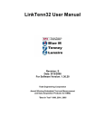
2.1 Point to Point
One IEEE Interface can control only one Z+ Power Supply. Refer to Fig.2-1. Each Power Supply must
be configured for IEEE communication interface. Each unit must have a unique address, ranging
from 01 to 31. Baud rate and address are automatically fixed to “57600" and "SCPI".
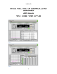
2.2 Multi Drop
One IEEE Interface can control more than one Z+ Power Supply. A maximum of 30 Z+ units can be
connected via RS485 interface to a Power Supply with the installed IEEE option. Refer to Fig.2-2.The
Power Supply connected to a PC via the GPIB cable must be configured for an IEEE communication
interface, the other must be configured for a RS485 interface. Each unit must have a unique address,
ranging from 01 to 31. IEEE module gets the address of the unit into which it is installed. For RS485
interface set Baud rate at “57600" bps and Communication Language to "SCPI".
2.2.1 Selecting One Power Supply in a Multi Drop Chain
All the SCPI commands may be sent to any one of the Power Supplies in an RS-485 chain by first
sending the INST:nSEL address command. All commands and queries will then apply only to
the selected Power Supply, until a new INST:nSEL is sent.
At power-up, the IEEE master Power Supply is automatically the one selected.
After sending INST:nSEL, it is recommended that you verify the command by sending INST:nSEL?,
otherwise the following commands may be sent to the wrong Power Supply.
Fig.2-1: Point To Point Connection
Fig.2-2: Multi Drop Connection
2.3 Communication Cables
•• GPIB cable - Use standard IEEE-488, 26 AWG GPIB cable up to 3 meters in length.
•• RS485 link cable - Use serial link cable with RJ-45 shielded connectors (P/N: GEN/RJ45). Refer
to Z+ Series User Manual Fig.7-8.
4
CHAPTER 3: CONFIGURATION
3.1 Configuration the IEEE Controller
A typical IEEE controller is a personal computer with an IEEE interface card. Each card vendor
supplies its own configuration instructions and interface software.
Each time the software is executed, the controller is configured as follows:
•• Controller Address = Power Supply address.
•• Serial bus Baud Rate = 57600
•• SCPI protocol.
•• EOI Flag = TRUE. The “End or Identify” is a control line in the IEEE cable that is initiated when
the last character of a message string is sent. It is not supported by this interface.
•• EOS Flag = FALSE: The “End of String”, used in some instruments to indicate the last character
of a message. It is required for this interface.
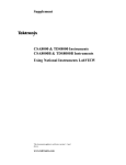
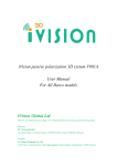
Fig.3-1: Front Panel
1.
2.
3.
4.
5.
6.
7.
8.
Fig.3-2: Rear Panel
AC ON/OFF Switch
REM LED/Buttom
Voltage Encoder
Voltage Display
Current Encoder
Current Display
RS-232/RS-485 INPUT Remote Serial Programming
RS-485 OUTPUT to other Z+ Power Supplies
5
3.2 Configuration the Power Supply
Refer to Fig.3-1.
3.2.1 To Select the Communication Interface
1. Press REM button. The LED is illuminated. “INtF" appears on Voltage display.
2. Press Voltage Encoder. Existing communication mode appears on Current display.
3. Turn Current Encoder until desired message appears; "IEEE" (for unit with IEEE option) or "485".
4. To select desired parameter press Current encoder.
3.2.2 To Select the Address
1. Press REM button. The LED is illuminated. “Ad r" appears on Current display.
2. Press Current Encoder. Existing address mode appears on Current display.
3. Turn Current Encoder until desired address appears.
4. To select desired address press Current encoder.
3.2.3 To Select the Baud Rate 57600. (485 Interface only)
1. Press REM button. The LED is illuminated. “INtF" appears on Voltage display.
2. Turn Voltage Encoder until "baUd" message appears on Current display
3. Press Current Encoder. Existing Baud Rate appears on Current display.
4. Turn Current Encoder until "57600" appears.
5. To select desired Baud Rate press Current encoder.
3.2.4 To Select the Communication Language SCPI. (485 interface only)
1. Press REM button. The LED is illuminated. “INtF" appears on Voltage display.
2. Turn Voltage Encoder until "La nG" message appears on Current display
3. Press Current Encoder. Existing Language appears on Current display.
4. Turn Current Encoder until "SCPI" appears.
5. To select desired Language press Current encoder.
For more information refer to section 4 of Z+ series User Manual
NOTE:
The power supply must be recycled bofore initiating IEEE communication intreface.
NOTE:
When new unit added to Multidrop chain connection, the Master unit (IEEE controller), must be recycled.
6
CHAPTER 4: PROGRAMMING COMMANDS
Communication over the GPIB interface meets IEEE 488.2 standards and is Standard Commands
for Programmable Instrumentation (SCPI) compliant.
4.1 SCPI Protocol
Refer to section 7.10 of Z+ series User Manual
4.2 SCPI Common Commands
Common commands are used to control instrument status registers, status reporting, synchronization,
data storage, and other common functions.
SCPI Command
Description
*CLS
Clear status
*ESE <NR1>
Standard event status enable
*ESE?
Return standard event status enable
*ESR?
Return event status register
*IDN?
Return instrument identification string
*OPC
Set ”operation complete” bit in ESR
*OPC?
Return a ”1” when operation command complete
*OPT?
Return option number
*PSC {1|0}
Power - ON status enable (1) /disable (0)
*PSC?
Power - ON status clear
*RCL {1|2|3|4}
Recalls a saved instrument state
*RST
Reset
*SAV {1|2|3|4}
Saves an instrument state
*SRE <NR1>
Set service request enable register
*SRE?
Return service request enable register
*STB?
Return status byte
*TRG
Trigger
For more information refer to section 7.11 of Z+ series User Manual.
7
4.3 SCPI Subsystem Commands
Subsystem commands control all Z+ functions. For a full command description refer to section
7.12 in Z+ series User Manual. Short list of Z+ series commands:
SCPI Command
Description
ABORt
Aborts the triggered action
DISPlay
[:WINDow]:STATe <bool>
Display ON/OFF*
[:WINDow]:FLASh <bool>
Display Flash
GLOBal
:CURRent
:[AMPLitude] <NRf+>
Set the output current for all power supplies
:VOLTage
:[AMPLitude] <NRf+>
Set the output voltage for all power supplies
:OUTPut:STATe <bool>
Enables/disables the all power supplies output
*RCL {1|2|3|4}
Recall setting for all power supplies
*RST
Reset all power supplies
*SAV {1|2|3|4}
Save settings for all power supplies
INITiate
[:IMMediate]
Trigger initiate
:CONTinuous <bool>
Enable/disable continuously trigger*
INSTrument
:COUPle ALL|NONE
Couple for all Z+ power supplies
:NSELect <NRf>
Select the power supply for communication*
MEASure
:CURRent[:DC]?
Returns the measured output current
:VOLTage[:DC]?
Returns the measured output voltage
:POWer[:DC]?
Returns the measured output power
OUTPut
[:STATe] <bool>
Enables/disable the supply output*
:PON
[:STATe] <bool>
Programs the Power-ON state*
:PROTection
:CLEar
Resets latched protection
:FOLDback
[:MODE] OFF|CC|CV
Set operation protection mode*
:DELay <NRf+>
Set protection delay*
:MODE <bool>
Enables/disable analog output ON/OFF control*
:ILC
:TTLTrg
:MODE OFF|FSTR|TRIG
Set output trigger mode*
:RELay {1|2}
[:STATe] <bool>
:MODE?
Set control pins status*
Returns the operation mode CV/CC/OFF
8
[SOURce]
:CURRent
[:LEVel]
[:IMMediate]
[:AMPLitude] <NRf+>
Set the output current*
:TRIGger <NRf+>
Set the triggered output current*
:MODE NONE|FIX|LIST|WAVE
Select arbitrary trigger control mode*
:VOLTage
[:LEVel]
[:IMMediate]
[:AMPLitude] <NRf+>
:TRIGger <NRf+>
Set the output voltage*
Set the triggered output voltage*
:PROTection
:LEVel <NRf+>
Set over-voltage protection level*
: LOW
:STATe UVP|UVL
Set under-voltage limit or protection mode*
:[LEVel] <NRf+>
Set under-voltage level*
:MODE NONE|FIX|LIST|WAVE
Select arbitrary control mode*
:LIST
:COUNt {0…9999,Inf}
Set number of time execution*
:CURRent <NRf+>
Set output current points*
:LOAD {1|2|3|4}
Load stored LIST program from memory
:STEP ONCE|AUTO
Set trigger depends execution step*
:STORe {1|2|3|4}
Store LIST program in memory
:DWELl <NRf+>
Set time interval*
:VOLTage <NRf+>
Set output voltage points*
:WAVE
:COUNt {1…9999,Inf}
Set number of time execution*
:CURRent <NRf+>
Set output current points*
:LOAD {1|2|3|4}
Load stored WAVE program from memory
:STEP ONCE|AUTO
Set trigger depends execution step*
:STORe {1|2|3|4}
Store WAVE program in memory
:TIME <NRf+>
Set slope time*
:VOLTage <NRf+>
Set output voltage points*
STATus
:OPERation
[:EVENt]?
Returns the value of the Event register
:CONDition?
Returns the value of the Condition register
:ENABle <NR1>
Enables specific bits in the Enable register*
:QUEStionable
[:EVENt]?
Returns the value of the Event register
:CONDition?
Returns the value of the Condition register
:ENABle <NR1>
Enables specific bits in the Enable register*
9
SYSTem
:ERRor:ENABle
Enable error message
:ERRor?
Read system error messages
:LANGuage GEN
Set communication language*
:REMote
[:STATe] LOC|REM|LLO
Set the remote/local state*
:VERSion?
Returns software revision
:DATE?
Returns calibration date
:PON
:TIME?
Response time from last reset
TRIGger
[:STARt]
Run trigger
:DELay <NRf+>
Set input trigger delay*
:SOURce EXTernal|BUS
Set input trigger source*
NOTE:
* Command query is available.
4.4 The Summary Registers
The INSTRUMENT SUMMARY EVENT REGISTER, ISUM1 through ISUM3 (Refer to Fig.4-2), will
record the address of the supply causing an SRQ. These are ‘EVENT’ registers and the bits will
remain set until read by the STAT:QUES:INST:ISUMn command. (Refer to Table 4-1)
Command
Description
STATus:QUEStionable
:INSTrument:ISUMmary1?
Reads the source of the SRQ in Logical Z+ Supplies 0 through 13
STATus:QUEStionable
:INSTrument:ISUMmary2?
Reads the source of the SRQ in Logical Z+ Supplies 14 through 27
STATus:QUEStionable
:INSTrument:ISUMmary3?
Reads the source of the SRQ in Logical Z+ Supplies 28 through 30
STATus:QUEStionable
:INSTrument:ISUMmary1:ENABle xx
Enable supplies to cause IEEE SRQ in Logical Z+ Supplies 0 through 13
STATus:QUEStionable
:INSTrument:ISUMmary2:ENABle xx
Enable supplies to cause IEEE SRQ in Logical Z+ Supplies 14 through
27
STATus:QUEStionable
:INSTrument:ISUMmary3:ENABle xx
Enable supplies to cause IEEE SRQ in Logical Z+ Supplies 28 through
30
STATus:QUEStionable
:INSTrument:ISUMmary1:ENABle?
Read which supplies can cause IEEE SRQ in Logical Z+ Supplies 0
through 13
STATus:QUEStionable
:INSTrument:ISUMmary2:ENABle?
Read which supplies can cause IEEE SRQ in Logical Z+ Supplies 14
through 27
STATus:QUEStionable
:INSTrument:ISUMmary3:ENABle?
Read which supplies can cause IEEE SRQ in Logical Z+ Supplies 28
through 30
Table 4-1: ISUM commands
10
4.5 Output Queue
Refer to section 9.6.16 of Z+ series User Manual.
4.6 Error Messages
Refer to section 9.6.17 of Z+ series User Manual.
4.7 Execution Time
Command execution time except for *CLS (150mS) is less than 15 milliseconds.
INST:NSEL 06
OUTP:STAT ON
:VOLT 15
WAVE:TIME 1,1,1,1,1,1,1,1,1,1,1,1
11 millisecond
12 millisecond
10 millisecond
14 millisecond
Query execution time is between 20-50 milliseconds. Response is dependent upon string length.
WAVE:VOLT?
SYST:ERR?
*IDN?
INST:NSEL?
45 millisecond
22 millisecond
38 millisecond
20 millisecond
It is required that the user adds a delay after a command before sending any further messages.
(Refer to Table 4-2)
ADDRESSED COMMAND/QUERY
10 milliseconds
GLOBAL COMMAND
20 milliseconds
Table 4-2: Addition of Delay
11
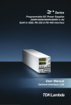
4.8 Register Structure
Fig.4-1: Status Register and SRQ Tree
12
Fig.4‐2: Instrument Summary Register Tree for Multi Drop Mode
13
CHAPTER 5: COMMUNICATION EXAMPLE
This section provides an example the National Instruments™ MAX program to communicate with
the Z+.
1. Run National Instruments™ MAX (Measurement & Automation Explorer) program
2. Select “Devices and Interfaces” -> “GPIB0” press Scan for Instruments. Refer to Fig.5-1
Fig.5-1: Scanning for Instrument
3. In the right window, click on Instrument0 and review the device properties. Refer to Fig.5-2
Fig.5-2: Instrument Properties
14
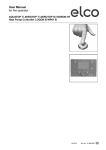
4. Click Communicate with Instrument in the GPIB Explorer toolbar. NI-488.2 Communicator
appears. Refer to Fig. 5-3
Fig.5-3: ID String Query
5. In the Send String box, *IDN? appears. Click Query. The ID string indicates the model, serial
number, firmware version and the GPIB card firmware version. This will be shown in the text
box below String Received. Refer to Fig.5-3.
15
NOTES
TDK-Lambda Americas Inc.
3055 Del Sol Boulevard San Diego, CA 92154 U.S.A.
Tel: +1-619-575-4400
Fax: +1-619-575-7185
www.us.tdk-lambda.com/lp
UK
TDK-Lambda UK Ltd.
Kingsley Avenue Ilfracombe, Devon
EX 34 8ES United Kingdom
Tel: +44-1271-856666 Fax: +44-1271-864894
E-mail: [email protected]
www.uk.tdk-lambda.com
FRANCE
TDK-Lambda France SAS
ZAC des Delaches
BP 1077 - Gometz le Chatel
91940 LES ULIS
Tel: +33 1 60 12 71 65
Fax: +33 1 60 12 71 66
E-mail: [email protected]
www.fr.tdk-lambda.com
GERMANY
TDK-Lambda Germany GmbH
Karl-Bold-Str.40,
D-77855 Achern, Germany
Tel: +49-7841-666-0 Fax: +49-7841-500-0
E-mail: [email protected]
www.de.tdk-lambda.com
AUSTRIA
TDK-Lambda Austria Sales Office
Aredstrasse 22,
A - 2544 Leobersdorf, Austria
Tel: +43-2256-65584 Fax: +43-2256-64512
E-mail: [email protected]
www.de.tdk-lambda.com
ITALY
TDK-Lambda Italy Sales Office
Via dei Lavoratori 128/130
IT20092 Cinisello Balsamo, Milano, Italy
Tel: +39-02-6129-3863 Fax: +39-02-6129-0900
E-mail: [email protected]
www.it.tdk-lambda.com
ISRAEL
TDK-Lambda Ltd.
Sales Office: Kibbutz Givat Hashlosha Tel-Aviv
4880000, Israel
Tel: +972-3-9024-333 Fax: +972-3-9024-777
Plant: 56 Haharoshet St.
Karmiel Industrial Zone 2165158, Israel
Tel: +972-4-9887-491 Fax: +972- 4-9583-071
www.tdk-lambda.co.il E-mail: [email protected]
JAPAN
TDK-Lambda Corporation
International Sales Divison
Nittetsu Bldg. 6F, 1-13-1 Nihonbashi, Chuo-ku, Tokyo 103-0027, Japan
Tel: +81-3-5201-7175
Fax: +81-3-5201-7287
www.tdk-lambda.com
CHINA
Shanghai Branch of Wuxi TDK-Lambda Electronic Co. Ltd.
28F, Xingyuan Technology Building No.418, Guiping Road,
Shanghai, China 200233
Tel: +86-21-6485-0777 Fax: +86-21-6485-0666
www. cn.tdk-lambda.com
Beijing Branch of Wuxi TDK-Lambda Electronic Co. Ltd.
Room 12B11-12B12, Unit 7 DACHENG SQUARE, No.28
Xuanwumenxi Street, Xuanwu District Beijing, 100053, CHINA
Tel: +86-10-6310-4872 Fax: +86-10-6310-4874
www. cn.tdk-lambda.com
Shenzhen Branch of Wuxi TDK-Lambda Electronics Co.Ltd.
Room 4302, Excellence Times Square Building,
4068 Yi Tian Road, Futian District,
Shenzhen, China 518048
Tel: +86 -755-83588261 Fax: +86 -755-83588260
www. cn.tdk-lambda.com
KOREA
TDK-Lambda Corporation Seoul Office
8F Songnam Bldg, 1358-6, Seocho-Dong,
Seocho-Gu, Seoul, 137-862 KOREA
Tel: +82-2-3473-7051
Fax: +82-2-3472-9137
www.tdk-lambda.co.kr
www.tdk-lambda.co.kr
SINGAPORE
TDK-Lambda Singapore Pte.Ltd.
Blk 1008 Toa Payoh North # 07-01/03
Singapore 318996
Tel: +65-6251-7211 Fax: +65-6250-9171
www.tdk-lambda.com.sg
INDIA
TDK-Lambda Bangalore Office
#526, Ground Floor, 10th Main, 7th Cross,
Jeevanbhimanagar , Bangalore 560 075
Karnataka , India
Tel: +91-80-43550 550
Fax: +91-80-43550 501
www.tdk-lambda.com.sg
MALAYSIA
TDK-Lambda Malaysia Sdn. Bhd.
c/o TDK (Malaysia) Sdn Bhd
Lot 709, Nilai Industrial Estate 71800 Nilai
Negeri Sembilan, Malaysia
Tel: + 60 6-799 1130
Fax: + 60 6 799 3277
www.tdk-lambda.com.my
TDK-Lambda EMEA
www.emea.tdk-lambda.com
Innovating Reliable Power
IA710-04-03E
AD0614
NORTH AMERICA