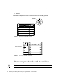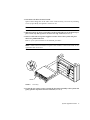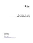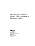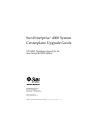
1
Sun Enterprise™ 4000 System
Centerplane Upgrade Guide
100 MHz Gigaplane Upgrade for the
Sun Enterprise 4000 System
Sun Microsystems, Inc.
901 San Antonio Road
Palo Alto, CA 94303-4900 USA
650 960-1300
Fax 650 969-9131
Part No. 805-7186-10
January 1999, Revision A
Send comments about this document to: [email protected]
Copyright 1999 Sun Microsystems, Inc., 901 San Antonio Road • Palo Alto, CA 94303 USA. All rights reserved.
This product or document is protected by copyright and distributed under licenses restricting its use, copying, distribution, and
decompilation. No part of this product or document may be reproduced in any form by any means without prior written authorization
of Sun and its licensors, if any. Third-party software, including font technology, is copyrighted and licensed from Sun suppliers.
Parts of the product may be derived from Berkeley BSD systems, licensed from the University of California. UNIX is a registered trademark in
the U.S. and other countries, exclusively licensed through X/Open Company, Ltd.
Sun, Sun Microsystems, the Sun logo, AnswerBook, Sun Enterprise, and Solaris are trademarks, registered trademarks, or service marks of Sun
Microsystems, Inc. in the U.S. and other countries. All SPARC trademarks are used under license and are trademarks or registered trademarks
of SPARC International, Inc. in the U.S. and other countries. Products bearing SPARC trademarks are based upon an architecture developed by
Sun Microsystems, Inc.
The OPEN LOOK and Sun™ Graphical User Interface was developed by Sun Microsystems, Inc. for its users and licensees. Sun acknowledges
the pioneering efforts of Xerox in researching and developing the concept of visual or graphical user interfaces for the computer industry. Sun
holds a non-exclusive license from Xerox to the Xerox Graphical User Interface, which license also covers Sun’s licensees who implement OPEN
LOOK GUIs and otherwise comply with Sun’s written license agreements.
RESTRICTED RIGHTS: Use, duplication, or disclosure by the U.S. Government is subject to restrictions of FAR 52.227-14(g)(2)(6/87) and
FAR 52.227-19(6/87), or DFAR 252.227-7015(b)(6/95) and DFAR 227.7202-3(a).
DOCUMENTATION IS PROVIDED “AS IS” AND ALL EXPRESS OR IMPLIED CONDITIONS, REPRESENTATIONS AND WARRANTIES,
INCLUDING ANY IMPLIED WARRANTY OF MERCHANTABILITY, FITNESS FOR A PARTICULAR PURPOSE OR NONINFRINGEMENT, ARE DISCLAIMED, EXCEPT TO THE EXTENT THAT SUCH DISCLAIMERS ARE HELD TO BE LEGALLY INVALID.
Copyright 1999 Sun Microsystems, Inc., 901 San Antonio Road • Palo Alto, CA 94303 Etats-Unis. Tous droits réservés.
Ce produit ou document est protégé par un copyright et distribué avec des licences qui en restreignent l’utilisation, la copie, la distribution, et la
décompilation. Aucune partie de ce produit ou document ne peut être reproduite sous aucune forme, par quelque moyen que ce soit, sans
l’autorisation préalable et écrite de Sun et de ses bailleurs de licence, s’il y en a. Le logiciel détenu par des tiers, et qui comprend la technologie
relative aux polices de caractères, est protégé par un copyright et licencié par des fournisseurs de Sun.
Des parties de ce produit pourront être dérivées des systèmes Berkeley BSD licenciés par l’Université de Californie. UNIX est une marque
déposée aux Etats-Unis et dans d’autres pays et licenciée exclusivement par X/Open Company, Ltd.
Sun, Sun Microsystems, le logo Sun, AnswerBook, Sun Enterprise, et Solaris sont des marques de fabrique ou des marques déposées, ou
marques de service, de Sun Microsystems, Inc. aux Etats-Unis et dans d’autres pays. Toutes les marques SPARC sont utilisées sous licence et
sont des marques de fabrique ou des marques déposées de SPARC International, Inc. aux Etats-Unis et dans d’autres pays. Les produits portant
les marques SPARC sont basés sur une architecture développée par Sun Microsystems, Inc.
L’interface d’utilisation graphique OPEN LOOK et Sun™ a été développée par Sun Microsystems, Inc. pour ses utilisateurs et licenciés. Sun
reconnaît les efforts de pionniers de Xerox pour la recherche et le développement du concept des interfaces d’utilisation visuelle ou graphique
pour l’industrie de l’informatique. Sun détient une licence non exclusive de Xerox sur l’interface d’utilisation graphique Xerox, cette licence
couvrant également les licenciés de Sun qui mettent en place l’interface d’utilisation graphique OPEN LOOK et qui en outre se conforment aux
licences écrites de Sun.
CETTE PUBLICATION EST FOURNIE "EN L’ETAT" ET AUCUNE GARANTIE, EXPRESSE OU IMPLICITE, N’EST ACCORDEE, Y
COMPRIS DES GARANTIES CONCERNANT LA VALEUR MARCHANDE, L’APTITUDE DE LA PUBLICATION A REPONDRE A UNE
UTILISATION PARTICULIERE, OU LE FAIT QU’ELLE NE SOIT PAS CONTREFAISANTE DE PRODUIT DE TIERS. CE DENI DE
GARANTIE NE S’APPLIQUERAIT PAS, DANS LA MESURE OU IL SERAIT TENU JURIDIQUEMENT NUL ET NON AVENU.
Please
Recycle
Contents
Preface
vii
Using UNIX Commands
vii
Typographic Conventions
Shell Prompts
viii
Related Documentation
1.
viii
ix
Sun Documentation on the Web
ix
Sun Welcomes Your Comments
ix
System Upgrade Procedure
Powering Off the System
1
1
Removing the Boards and Assemblies
Removing the Outer Panels
Replacing the Centerplane
5
8
Replacing the Outer Panels
11
Replacing the Boards and Assemblies
Replacing the Clock Board
12
13
Updating the System Flash PROM
Replacing the CD-ROM Drive
Powering On the System
2
14
15
17
iii
iv
Sun Enterprise 4000 System Centerplane Upgrade Guide • January 1999
Figures
FIGURE 1
Keyswitch in Standby Position 2
FIGURE 2
AC Power Switch—Rear View 2
FIGURE 3
SCSI Tray
FIGURE 4
Keyswitch Assembly
FIGURE 5
Fan Tray Assembly—System Rear
FIGURE 6
Outer Panels—Sun Enterprise 4000 System
FIGURE 7
Orientation of Empty System Chassis
FIGURE 8
Front and Rear of the System Chassis
FIGURE 9
Centerplane Replacement Detail
FIGURE 10
Clock Board and TOD/NVRAM Location 13
FIGURE 11
Removing the SCSI Tray 16
FIGURE 12
Keyswitch Standby and On Positions
3
4
5
7
8
9
10
17
v
vi
Sun Enterprise 4000 System Centerplane Upgrade Guide • January 1999
Preface
The Sun Enterprise 4000 System Centerplane Upgrade Guide provides procedures for
the 100 MHz gigaplane upgrade for Sun Enterprise™ 4000 systems. As part of this
upgrade, the CD-ROM drive and clock board are replaced, and the flash PROM
updated. These instructions are designed to be performed only by an experienced
service provider.
Using UNIX Commands
This document may not contain information on basic UNIX® commands and
procedures such as shutting down or booting the system, and configuring devices.
See one or more of the following for this information:
■
Solaris Handbook for Sun Peripherals
■
AnswerBook™ online documentation for the Solaris™ software environment
■
Other software documentation that you received with your system
vii
Typographic Conventions
TABLE P-1
Typographic Conventions
Typeface
Meaning
Examples
AaBbCc123
The names of commands, files,
and directories; on-screen
computer output
Edit your .login file.
Use ls -a to list all files.
% You have mail.
AaBbCc123
What you type, when
contrasted with on-screen
computer output
% su
Password:
AaBbCc123
Book titles, new words or
terms, words to be emphasized
Read Chapter 6 in the User’s Guide.
These are called class options.
You must be superuser to do this.
Command-line variable;
replace with a real name or
value
To delete a file, type rm filename.
Shell Prompts
TABLE P-2
viii
Shell Prompts
Shell
Prompt
C shell
machine_name%
C shell superuser
machine_name#
Bourne shell and Korn shell
$
Bourne shell and Korn shell superuser
#
Sun Enterprise 4000 System Centerplane Upgrade Guide • January 1999
Related Documentation
TABLE P-3
Related Documentation
Application
Title
Part Number
Installation
Ultra Enterprise 6000/5000/4000 Systems
Installation Guide
802-3844
Service
Ultra Enterprise 6000/5000/4000 Systems
Manual
802-3845
Sun Documentation on the Web
The docs.sun.comsm web site enables you to access Sun technical documentation
on the Web. You can browse the docs.sun.com archive or search for a specific book
title or subject at:
http://docs.sun.com
Sun Welcomes Your Comments
We are interested in improving our documentation and welcome your comments
and suggestions. You can email your comments to us at:
[email protected]
Please include the part number of your document in the subject line of your email.
ix
x
Sun Enterprise 4000 System Centerplane Upgrade Guide • January 1999
System Upgrade Procedure
This chapter gives detailed instructions for upgrading your Sun Enterprise 4000
system. The upgrade procedure includes:
■
■
■
■
■
■
■
■
■
■
Powering off the system—page 1
Removing all Boards and Assemblies—page 2
Removing the Outer Panels—page 5
Replacing the Centerplane—page 5
Replacing the Outer Panels
Replacing all Boards and Assemblies—page 12
Replacing the Clock Board—page 13
Replacing the CD-ROM Drive—page 15
Updating the System Flash PROM—page 14
Powering on the System—page 17
Powering Off the System
1. Halt the system using the appropriate commands and wait for the system-halted
message and the boot monitor prompt.
Refer to the Solaris Handbook for SMCC Peripherals that corresponds to your operating
system.
Caution – Failure to halt the operating system properly can result in a loss of disk
drive data.
2. Turn off the system power in this order:
a. External drives and expansion cabinets (if any)
b. System cabinet
1
c. Terminal
3. Turn the front panel keyswitch counterclockwise to the Standby position.
Standby
FIGURE 1
Keyswitch in Standby Position
4. Turn the AC power switch to off.
Power switch
FIGURE 2
AC Power Switch—Rear View
Removing the Boards and Assemblies
Caution – Use a grounding wrist strap to prevent static damage.
2
Sun Enterprise 4000 System Centerplane Upgrade Guide • January 1999
1. Disconnect all cables from the boards.
Squeeze the locking tabs on the sides of the connector body, or loosen any retaining
screws (if provided), and pull the connectors out.
Note – Label all cables for reconnection.
2. With wrist strap on, insert a screwdriver in the notch at the top of the SCSI tray to
pull out the tray and separate it from the rear slip connector ( FIGURE 3).
3. Remove all boards and power supplies from the front of the system and place
them on a padded ESD mat.
Refer to your system manual for the detailed procedure.
Note – Label each board with its respective slot number, so that each board can be
replaced in the correct slot.
Notch
FIGURE 3
SCSI Tray
4. Loosen the two captive screws securing the keyswitch assembly to the system and
gently pull the keyswitch from the enclosure (FIGURE 4).
System Upgrade Procedure
3
Captive
Screws
FIGURE 4
Keyswitch Assembly
5. Remove all the boards and power supplies from the rear of the system and place
them on a padded ESD mat.
Refer to your system manual for the detailed procedure.
Note – Label each board with its respective slot number, so that each board can be
replaced in the correct slot.
6. Remove the fan tray assembly from the rear of the system (FIGURE 5).
4
Sun Enterprise 4000 System Centerplane Upgrade Guide • January 1999
FIGURE 5
Fan Tray Assembly—System Rear
7. Disconnect any remaining cables from the system.
Note – Label all cables for reconnection.
Removing the Outer Panels
1. Ensure that all cables have been disconnected and that the keyswitch is in the
standby position with the key removed.
2. Remove the upper bezel:
a. Press the lower left and right sides of the upper bezel to release the locking
tabs.
b. Swing the bottom edge of the bezel toward you to release the tabs in the top of
the bezel, then lift the bezel off.
3. Remove the right and left side panels:
a. Push the side panel back approximately 3/4 of an inch (2 cm).
System Upgrade Procedure
5
b. Pull the bottom of the panel away from the side, then lift the panel off the
chassis.
4. Remove the top panel:
a. Remove the square inserts from the corners of the top panel.
Press the small dot to tilt the insert up, then lift it off.
b. Lift the front corners of the top panel 1/8 inch (3 mm) by pressing the two
locking tabs at the front corners of the panel.
c. Firmly push the panel back 1 inch (2.5 cm), then lift it off.
5. Remove the bottom panel:
a. Turn the chassis upside down.
b. Remove the four feet by removing the screw that holds each foot.
c. Lift the front corners of the bottom panel, push the panel toward the back of
the chassis, and lift the panel off.
6
Sun Enterprise 4000 System Centerplane Upgrade Guide • January 1999
1
2
3
6
7
4
8
5
Key
Description
1
Top panel
2
Square insert
3
Side panel
4
Foot
5
Bottom panel
6
Side panel
7
Upper bezel
8
Lower bezel
FIGURE 6
Outer Panels—Sun Enterprise 4000 System
6. Remove the lower bezel:
a. With the chassis still upside down, use a flat-bladed screwdriver to lift the left
side of the lower bezel approximately 1/8 of an inch (3 mm).
b. Slide the bezel 1/4 of an inch (6 mm) to the left and lift it off the chassis.
System Upgrade Procedure
7
7. Place the empty system chassis front side down (FIGURE 7).
Rear
chassis
Front
chassis
FIGURE 7
Orientation of Empty System Chassis
Replacing the Centerplane
The system chassis is in two sections consisting of a front chassis and a rear chassis.
The centerplane is located between the two sections of the chassis and is fastened to
the front chassis.
Caution – Use a grounding wrist strap to prevent static damage.
1. Remove the 26 screws that surround the center seam of the system chassis.
2. Lift and remove the rear chassis section and set it aside (FIGURE 8).
8
Sun Enterprise 4000 System Centerplane Upgrade Guide • January 1999
Rear
chassis
Front
chassis
FIGURE 8
Front and Rear of the System Chassis
System Upgrade Procedure
9
3. Remove the 20 screws that hold the centerplane to the front chassis ( FIGURE 9).
Centerplane
Front chassis
FIGURE 9
Centerplane Replacement Detail
Caution – Use a grounding wrist strap to prevent static damage.
4. With a wrist strap on, lift the centerplane out and set it aside.
Note – Remember the proper orientation of the centerplane when removing it from
the front chassis.
5. Place the new centerplane into the front chassis.
Be sure the centerplane has the proper orientation when placed in the front chassis.
6. Replace the 20 screws that hold the centerplane to the front chassis.
7. Place the rear chassis on the front chassis.
8. Replace the 26 screws securing the front and rear chassis together.
10
Sun Enterprise 4000 System Centerplane Upgrade Guide • January 1999
Replacing the Outer Panels
1. Place the system front side down as shown in FIGURE 7.
2. Replace the lower bezel:
a. Align the bezel 1/4 of an inch (6 mm) to the left of the system chassis to engage
the tabs.
b. Slide it to the right until it locks into position.
3. Replace the bottom panel.
Set the panel about an inch back from the front of the system chassis. Push the panel
forward until it locks into place.
4. Secure each foot to the bottom of the system chassis with the screws removed
previously.
5. Turn the enclosure over so that the feet are supporting the chassis.
6. Replace the top panel:
a. Set the panel about an inch back from the front of the system chassis. Push the
panel forward until it locks into place.
b. Align the small dots on the square inserts with the dots on the top panel and
press the inserts until they engage.
7. Replace the right and left side panels:
a. With the panel set about 3/4 of an inch (2 cm) back from the system chassis,
align the top and bottom panel tabs with the corresponding slots on the system.
b. Push the panel forward to lock it in place.
8. Replace the upper bezel:
a. Set the tabs at the top of the bezel into the corresponding slots at the top of the
system chassis.
b. Press the bottom of the bezel into place.
System Upgrade Procedure
11
Replacing the Boards and Assemblies
Caution – Use a grounding wrist strap to prevent static damage.
1. Replace all the boards and power supplies in the front of the system.
Note – Insert boards component side down in the front of the system.
Refer to your system manual for the detailed procedure.
2. Tighten the bottom three captive screws on the SCSI tray to secure the tray to the
enclosure (FIGURE 3).
3. Replace the keyswitch assembly in the front of the system (FIGURE 4).
4. Replace the fan tray assembly in the rear of the system (FIGURE 5).
5. Replace the boards and power supplies in the rear of the system.
Note – Insert boards component side up in the rear of the system.
6. Replace the top cover by sliding it over the key slots until it fits securely on the
main chassis.
7. Replace the square inserts on the corners of the top panel (FIGURE 6).
8. Place each side vent alongside the main chassis and push the vent forward until it
stops.
9. Replace the top bezel.
10. Ensure that the keyswitch is in the Standby position (FIGURE 1).
11. Reattach the I/O cables.
12. Reattach the power cables.
12
Sun Enterprise 4000 System Centerplane Upgrade Guide • January 1999
Replacing the Clock Board
The clock board is located at the top rear of the system, below the peripheral power
supply. After replacing the clock board, update the system flash PROM as shown in
“Updating the System Flash PROM” on page 14.
Note – The TOD/NVRAM chip must be removed from the old clock board and installed
on the upgrade clock board since it contains the host ID and Ethernet ID.
1. Loosen the two captive screws securing the clock board to the system chassis.
2. Pull the ends of both extraction levers outward simultaneously to release the
board from the centerplane receptacles (FIGURE 10).
3. Place the clock board on a padded ESD mat.
!
Caution – Use a grounding wrist strap when handling the TOD/NVRAM chip.
.
TOD/NVRAM
Captive screw
Extraction lever
FIGURE 10
Clock Board and TOD/NVRAM Location
System Upgrade Procedure
13
4. With a wrist strap attached, gently pull the TOD/NVRAM chip from the clock
board.
5. Align the TOD/NVRAM chip removed from the original clock board with the
connector on the upgrade clock board so that pin 1 on the chip is aligned with pin
1 on the board.
■
■
A small crescent-shape indentation on both the chip and the connector denotes
the top (mate these areas).
A small round indentation on the corner of the chip denotes pin 1.
6. Ensure that all pins on the TOD/NVRAM chip are aligned correctly with the
board connector pins.
!
Caution – To avoid system damage, make sure that you connect pin 1 on the TOD
chip into pin 1 on the board connector.
7. Gently press on the top of the chip to seat it.
8. Carefully insert the board in the clock board slot component-side up, ensuring
that the board does not slip out of the card guides.
9. Use the open extraction levers to seat the board. Push the board into the card cage,
then simultaneously press both extraction levers to seat the board on the
centerplane.
Do not press on the board front panel to seat it, doing so will damage the connector
pins.
10. Secure the board to the chassis using the two captive screws, one on each side.
11. Connect any applicable interface cables to the front panel of the board.
This concludes the hardware portion of the clock board upgrade. Continue with the
next section, “Updating the System Flash PROM” to complete the procedure.
Updating the System Flash PROM
After replacing the clock board, update the system flash PROM. If you have internet
access, the patch can be downloaded using the following procedure. If you do not
have internet access, obtain the PROM patch software from your local Sun service
provider.
After the system flash PROM is reprogrammed, the flash utility attempts to reboot
the system. If the system fails to auto reboot, power cycle or reset the system by
pressing the reset button.
14
Sun Enterprise 4000 System Centerplane Upgrade Guide • January 1999
!
Caution – Some combinations of old and new PROM versions are incompatible,
and flash programming may cause default NVRAM values to overwrite customized
NVRAM variables. Be sure to record the custom and default values displayed so that
you can restore them afterward if necessary.
1. Through your web browser, go to http://sunsolve.sun.com.
2. On the SunSolve Online web page, select these links in order:
a. Public Patches
b. Security and Recommended Patches
c. Detailed List (in the Hardware category)
d. 103346-11
The last link downloads a compressed tar file into your working directory.
3. Uncompress and untar the 103346-11.tar.Z file.
4. Change directory to the 103346-11 directory.
5. Read the README file in this directory for further instructions.
Replacing the CD-ROM Drive
Refer to your server system reference manual for further information on replacing a
device.
Note – For cooling purposes, the tape drive must be installed on the side nearest the
keyswitch.
1. Loosen the bottom three captive screws securing the SCSI tray to the chassis.
System Upgrade Procedure
15
2. With a wrist strap on, insert a screwdriver in the notch at the top of the SCSI tray
to pull out the tray and separate it from the rear slip connectors.
1
2
3
5
4
Key
Description
1
Screw securing tray cover
2
Captive screw
3
Notch
4
CD-ROM drive
5
Tray cover
FIGURE 11
Removing the SCSI Tray
3. Remove the seven screws on top of the SCSI tray to lift off the tray cover and
access the CD-ROM drive.
4. Remove the CD-ROM drive from the SCSI tray:
a. Loosen the three captive screws securing the CD-ROM drive to the SCSI tray.
b. Remove the mounting plate from the CD-ROM drive being replaced and attach
it to the replacement CD-ROM drive.
5. Install the CD-ROM drive:
a. Set the replacement CD-ROM drive SCSI address to 6.
16
Sun Enterprise 4000 System Centerplane Upgrade Guide • January 1999
b. Tighten the three captive screws to secure the CD-ROM drive to the SCSI tray.
6. Replace the tray cover with the seven screws removed in Step 3.
7. Place the SCSI tray into the system and tighten the three captive screws securing
it to the enclosure (FIGURE 11).
Powering On the System
Note – Refer to Chapter 12 in your system reference manual for additional
information on restarting your Sun Enterprise system.
1. Ensure that the keyswitch is in the Standby position (FIGURE 12).
.
On
Standby
FIGURE 12
Keyswitch Standby and On Positions
2. Reattach the I/O cables and power cables.
3. Turn on power to the terminal to view system messages.
4. Turn the keyswitch to the On position.
5. Watch the terminal screen for any POST error messages.
System Upgrade Procedure
17
18
Sun Enterprise 4000 System Centerplane Upgrade Guide • January 1999