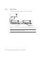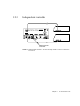
1
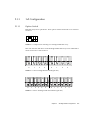
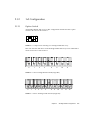
Sun™ StorEdge™ A3500
Hardware Configuration
Guide
Sun Microsystems, Inc.
901 San Antonio Road
Palo Alto, CA 94303-4900 USA
650 960-1300
Fax 650 969-9131
Part No. 805-4981-11
September 1998, Revision A
Send comments about this document to: [email protected]
Copyright 1998 Sun Microsystems, Inc., 901 San Antonio Road • Palo Alto, CA 94303 USA. All rights reserved.
Portions copyright 1997 Symbios Logic, Inc. All rights reserved.
This product or document is protected by copyright and distributed under licenses restricting its use, copying, distribution, and decompilation.
No part of this product or document may be reproduced in any form by any means without prior written authorization of Sun and its licensors,
if any. Third-party software, including font technology, is copyrighted and licensed from Sun suppliers.
Parts of the product may be derived from Berkeley BSD systems, licensed from the University of California. UNIX is a registered trademark in
the U.S. and other countries, exclusively licensed through X/Open Company, Ltd.
Sun, Sun Microsystems, the Sun logo, AnswerBook, StorEdge, and Solaris are trademarks, registered trademarks, or service marks of Sun
Microsystems, Inc. in the U.S. and other countries. All SPARC trademarks are used under license and are trademarks or registered trademarks
of SPARC International, Inc. in the U.S. and other countries. Products bearing SPARC trademarks are based upon an architecture developed by
Sun Microsystems, Inc.
The OPEN LOOK and Sun™ Graphical User Interface was developed by Sun Microsystems, Inc. for its users and licensees. Sun acknowledges
the pioneering efforts of Xerox in researching and developing the concept of visual or graphical user interfaces for the computer industry. Sun
holds a non-exclusive license from Xerox to the Xerox Graphical User Interface, which license also covers Sun’s licensees who implement OPEN
LOOK GUIs and otherwise comply with Sun’s written license agreements.
RESTRICTED RIGHTS: Use, duplication, or disclosure by the U.S. Government is subject to restrictions of FAR 52.227-14(g)(2)(6/87) and
FAR 52.227-19(6/87), or DFAR 252.227-7015(b)(6/95) and DFAR 227.7202-3(a).
DOCUMENTATION IS PROVIDED “AS IS” AND ALL EXPRESS OR IMPLIED CONDITIONS, REPRESENTATIONS AND WARRANTIES,
INCLUDING ANY IMPLIED WARRANTY OF MERCHANTABILITY, FITNESS FOR A PARTICULAR PURPOSE OR NONINFRINGEMENT, ARE DISCLAIMED, EXCEPT TO THE EXTENT THAT SUCH DISCLAIMERS ARE HELD TO BE LEGALLY INVALID.
Copyright 1998 Sun Microsystems, Inc., 901 San Antonio Road • Palo Alto, CA 94303 Etats-Unis. Tous droits réservés.
Des portions de ce produit sont protégées par un copyright (1997) de Symbios Logic, Inc. Tous droits réservés.
Ce produit ou document est protégé par un copyright et distribué avec des licences qui en restreignent l’utilisation, la copie, la distribution, et la
décompilation. Aucune partie de ce produit ou document ne peut être reproduite sous aucune forme, par quelque moyen que ce soit, sans
l’autorisation préalable et écrite de Sun et de ses bailleurs de licence, s’il y en a. Le logiciel détenu par des tiers, et qui comprend la technologie
relative aux polices de caractères, est protégé par un copyright et licencié par des fournisseurs de Sun.
Des parties de ce produit pourront être dérivées des systèmes Berkeley BSD licenciés par l’Université de Californie. UNIX est une marque
déposée aux Etats-Unis et dans d’autres pays et licenciée exclusivement par X/Open Company, Ltd.
Sun, Sun Microsystems, le logo Sun, AnswerBook,StorEdge, et Solaris sont des marques de fabrique ou des marques déposées, ou marques de
service, de Sun Microsystems, Inc. aux Etats-Unis et dans d’autres pays. Toutes les marques SPARC sont utilisées sous licence et sont des
marques de fabrique ou des marques déposées de SPARC International, Inc. aux Etats-Unis et dans d’autres pays. Les produits portant les
marques SPARC sont basés sur une architecture développée par Sun Microsystems, Inc.
L’interface d’utilisation graphique OPEN LOOK et Sun™ a été développée par Sun Microsystems, Inc. pour ses utilisateurs et licenciés. Sun
reconnaît les efforts de pionniers de Xerox pour la recherche et le développement du concept des interfaces d’utilisation visuelle ou graphique
pour l’industrie de l’informatique. Sun détient une licence non exclusive de Xerox sur l’interface d’utilisation graphique Xerox, cette licence
couvrant également les licenciés de Sun qui mettent en place l’interface d’utilisation graphique OPEN LOOK et qui en outre se conforment aux
licences écrites de Sun.
CETTE PUBLICATION EST FOURNIE "EN L’ETAT" ET AUCUNE GARANTIE, EXPRESSE OU IMPLICITE, N’EST ACCORDEE, Y
COMPRIS DES GARANTIES CONCERNANT LA VALEUR MARCHANDE, L’APTITUDE DE LA PUBLICATION A REPONDRE A UNE
UTILISATION PARTICULIERE, OU LE FAIT QU’ELLE NE SOIT PAS CONTREFAISANTE DE PRODUIT DE TIERS. CE DENI DE
GARANTIE NE S’APPLIQUERAIT PAS, DANS LA MESURE OU IL SERAIT TENU JURIDIQUEMENT NUL ET NON AVENU.
Contents
Preface
1.
Host Connections
1-1
1.1
Configuration Guidelines
1.2
Supported Host Configurations
1.3
2.
v
1.2.1
Single Host
1.2.2
Daisy Chain
1.2.3
Independent Controller
1.2.4
Multi-Initiator
2.2
2.3
1-3
1-3
1-4
1-5
1-6
Ultra 2 Host System—Power Connection Requirement
StorEdge A3500 Configurations
2.1
1-2
2-1
StorEdge D1000 Disk Array Settings
2.1.1
1x2 Configuration
2-3
2.1.2
1x5 Configuration
2-5
2.1.3
2x7 Configuration
2-7
2.1.4
3x15 Configuration
1x2 Cabling
2-2
2-9
2-11
2.2.1
SCSI Cabling
2.2.2
Power Connections
1x5 Cabling
1-7
2-11
2-13
2-14
Contents
iii
2.4
2.5
iv
2.3.1
SCSI Cabling
2.3.2
Power Connections
2x7 Cabling
2-14
2-17
2.4.1
SCSI Cabling
2.4.2
Power Connections
3x15 Cabling
2-16
2-17
2-19
2-20
2.5.1
SCSI Cabling
2-21
2.5.2
Power Connections
2.5.3
Connecting to AC Power Source
2.5.4
Power Connections
2-25
2-26
Sun StorEdge A3500 Hardware Configuration Guide • September 1998
2-25
Preface
Sun StorEdge A3500 Hardware Configuration Guide provides configuration instructions
for the Sun™ StorEdge™ A3500 systems. These instructions are designed for an
experienced system administrator.
Using UNIX Commands
This document does not contain information on basic UNIX® commands and
procedures such as shutting down the system, booting the system, and configuring
devices.
See one or more of the following for this information:
■
Solaris 2.x Handbook for SMCC Peripherals
■
AnswerBook™ online documentation for the Solaris™ 2.x software environment
■
Other software documentation that you received with your system
v
Typographic Conventions
TABLE P-1
Typographic Conventions
Typeface or
Symbol
Meaning
Examples
AaBbCc123
The names of commands, files,
and directories; on-screen
computer output.
Edit your .login file.
Use ls -a to list all files.
% You have mail.
AaBbCc123
What you type, when
contrasted with on-screen
computer output.
% su
Password:
AaBbCc123
Book titles, new words or
terms, words to be emphasized.
Command-line variable;
replace with a real name or
value.
Read Chapter 6 in the User’s Guide.
These are called class options.
You must be root to do this.
To delete a file, type rm filename.
Shell Prompts
TABLE P-2
vi
Shell Prompts
Shell
Prompt
C shell
machine_name%
C shell superuser
machine_name#
Bourne shell and Korn shell
$
Bourne shell and Korn shell superuser
#
Sun StorEdge A3500 Hardware Configuration Guide • September 1998
Related Documentation
TABLE P-3
Related Documentation
Title
Part Number
Sun StorEdge A3000 Controller Module Guide
805-4980-xx
Sun StorEdge A3500 Task Map
805-4982-xx
Sun Documentation on the Web
The docs.sun.comsm web site enables you to access Sun technical documentation
on the Web. You can browse the docs.sun.com archive or search for a specific book
title or subject at:
http://docs.sun.com
Sun Welcomes Your Comments
We are interested in improving our documentation and welcome your comments
and suggestions. You can email your comments to us at:
[email protected]
Please include the part number of your document in the subject line of your email.
vii
viii
Sun StorEdge A3500 Hardware Configuration Guide • September 1998
CHAPTER
1
Host Connections
This chapter contains configurations for one or two Sun StorEdge A3000 controller
modules connected to one or more hosts. It also contains information about
connecting power to an Ultra™ host system.
■
■
■
Configuration Guidelines—page 1-2
Supported Host Configurations—page 1-3
■
Single Host—page 1-3
■
Daisy Chain—page 1-4
■
Independent Controller—page 1-5
■
Multi-Initiator—page 1-6
Ultra 2 Host System—Power Connection Requirement—page 1-7
1-1
1.1
Configuration Guidelines
Use the following guidelines for installing and cabling or reconfiguring your system.
■
Do not exceed a SCSI bus length of 25 meters.
■
Make sure that the last Sun StorEdge A3000 controller module in any daisy chain
has a total of two terminators, one in each SCSI OUT port.
■
If you are adding a controller module to an already existing configuration, halt all
activity on the SCSI bus before removing any SCSI cables.
■
Once you finish cabling the devices and powering on, reboot the system by
typing boot -r at the ok prompt before beginning any SCSI bus activity.
Perform a system check to make sure that SCSI connections are secure. Look for fault
LEDs on the hardware or error messages in the RAID Manager GUI.
Note – Refer to your server and rack documentation for instructions on grounding
the StorEdge A3500 cabinet.
1-2
Sun StorEdge A3500 Hardware Configuration Guide • September 1998
1.2
Supported Host Configurations
The examples that follow show the cable connections for configurations that are
supported by Sun Microsystems™.
1.2.1
Single Host
Differential SCSI
terminators
FIGURE 1-1
Single Host Connected to a Sun StorEdge A3000 Controller Module
Chapter 1
Host Connections
1-3
1.2.2
Daisy Chain
You can daisy chain controller modules in the same or separate cabinets.
SCSI cables
FIGURE 1-2
Differential SCSI
terminators
Two Sun StorEdge A3000 Controller Modules Daisy Chained to One Host
Note – The SCSI cables between the two controller modules are crossed to prevent
the SCSI IDs for the controllers from conflicting.
1-4
Sun StorEdge A3500 Hardware Configuration Guide • September 1998
1.2.3
Independent Controller
Differential SCSI
terminators
FIGURE 1-3
Independent Controller—One Sun StorEdge A3000 Controller Connected to
Two Hosts
Chapter 1
Host Connections
1-5
1.2.4
Multi-Initiator
FIGURE 1-4
Two-Node Multi-Initiator Configuration
Note – For more detailed information regarding the two-node multi-initiator
configuration, such as setting host SCSI IDs, refer to the SPARCcluster™ PDB™
documentation that is shipped with the host system.
1-6
Sun StorEdge A3500 Hardware Configuration Guide • September 1998
1.3
Ultra 2 Host System—Power Connection
Requirement
You can connect a controller module to an Ultra 2 host system; however, you must
connect the power cord of the Ultra 2 host to one of the AC power sequencers in the
expansion cabinet that contains the controller module.
You need to order one of the following power cords depending on the type of power
sequencer in the expansion cabinet (FIGURE 1-5):
■
■
Ultra™ Enterprise™ expansion cabinet and StorEdge expansion cabinet—
part number 530-2197-xx
56-Inch Data Center expansion cabinet—part number 180-1189-xx (United States)
or part number 180-1190-xx NEMA (European)
Caution – Failure to connect the power cord correctly as described here may cause
excessive ground current that could damage the system.
Plug in Ultra 2
power cord here
Ultra Enterprise
expansion cabinet
and StorEdge
expansion cabinet
power sequencer
FIGURE 1-5
56-inch data center
expansion cabinet
power sequencer
AC Power Sequencers—Ultra 2 Power Connector
Chapter 1
Host Connections
1-7
1. Gain access to the AC power sequencers.
See the documentation that came with the expansion cabinet.
2. Route the power cable from the Ultra 2 host under the expansion cabinet frame on
the same side as the power sequencer.
3. Plug the power cord from the Ultra 2 host into the top power connector of either
power sequencer (FIGURE 1-5).
The power connectors are located on the other side of the power sequencer from the
main switch.
4. Reassemble the expansion cabinet.
See the documentation that came with the expansion cabinet.
1-8
Sun StorEdge A3500 Hardware Configuration Guide • September 1998
CHAPTER
2
StorEdge A3500 Configurations
This chapter contains information about setting up the following configurations:
■
■
■
■
One controller module with two StorEdge D1000 disk arrays (1x2)
One controller module with five StorEdge D1000 disk arrays (1x5)
Two controller modules with seven StorEdge D1000 disk arrays (2x7)
Three controller modules with fifteen StorEdge D1000 disk arrays (3x15)
The chapter is divided into the following sections:
■
StorEdge D1000 Disk Array Settings—page 2-2
■
1x2 Configuration—page 2-3
■
1x5 Configuration—page 2-5
■
2x7 Configuration—page 2-7
■
3x15 Configuration—page 2-9
■
1x2 Cabling—page 2-11
■
SCSI Cabling—page 2-11
■
Power Connections—page 2-13
■
1x5 Cabling—page 2-14
■
SCSI Cabling—page 2-14
■
Power Connections—page 2-16
2x7 Cabling—page 2-17
■
SCSI Cabling—page 2-17
■
Power Connections—page 2-19
3x15 Cabling—page 2-20
■
SCSI Cabling—page 2-21
■
Power Connections—page 2-25
■
■
2-1
2.1
StorEdge D1000 Disk Array Settings
This section describes how to set the following attributes for StorEdge D1000
disk arrays (FIGURE 2-1) in 1x2, 1x5, 2x7, and 3x15 configurations:
■
■
■
Option switch
Module ID
SCSI jumper cables and terminators
Option Switch
Module ID
IN/OUT-1
IN/OUT-1
IN/OUT -2
Rear
FIGURE 2-1
2-2
StorEdge D1000 Disk Array
Sun StorEdge A3500 Hardware Configuration Guide • September 1998
IN/OUT -2
2.1.1
1x2 Configuration
2.1.1.1
Option Switch
Both disk arrays have split busses. Their option switches should be set as shown in
FIGURE 2-2.
5
4 3
FIGURE 2-2
2 1
1x2 Option Switch Settings for StorEdge D1000 Disk Array
This will cause the disk drives in the StorEdge D1000 disk arrays to be numbered as
shown in FIGURE 2-3 and FIGURE 2-4.
0
1
FIGURE 2-3
0
1
FIGURE 2-4
2
3
0
1
2
3
8-drive StorEdge D1000 SCSI ID (Split bus)
2
3
4
5
0
1
2
3
4
5
12-drive StorEdge D1000 SCSI Disk ID (Split bus)
Chapter 2
StorEdge A3500 Configurations
2-3
2.1.1.2
Module ID Switch
Ensure that the module IDs for the StorEdge D1000 disk arrays are set according to .
1x2 Module ID Switch Settings
Disk array number
Module ID setting
2 (Top)
2
1 (Bottom)
1
Note – Since the top and bottom disk arrays are split between one controller
module, the Module IDs will overlap. This may result in error messages while the
host system is booting. The ASC/ASCQ codes for this error is 98/01 and the Sense
Key is 6. These error messages are information only and will not impact system
performance.
2.1.1.3
SCSI Jumper Cables and Terminators
The disk arrays should have differential SCSI terminators on the inside IN/OUT-1
and IN/OUT-2 SCSI connectors. This configuration is shown in FIGURE 2-11
2-4
Sun StorEdge A3500 Hardware Configuration Guide • September 1998
2.1.2
1x5 Configuration
2.1.2.1
Option Switch
All StorEdge D1000 disk arrays in this configuration should have their option
switches set as shown in FIGURE 2-5.
5
4 3
FIGURE 2-5
2 1
1x5 Option Switch Settings for StorEdge D1000 Disk Array
This will cause the disk drives in the StorEdge D1000 disk arrays to be numbered as
shown in FIGURE 2-6 and FIGURE 2-7.
0
1
FIGURE 2-6
0
1
FIGURE 2-7
2
3
8
9
10
11
8-drive StorEdge D1000 SCSI ID (Single Bus)
2
3
4
5
8
9
10
11
12
13
12-drive StorEdge D1000 SCSI ID (Single Bus)
Chapter 2
StorEdge A3500 Configurations
2-5
2.1.2.2
Module ID Switch
Ensure that the module IDs for the StorEdge D1000 disk arrays are set according to
TABLE 2-1.
TABLE 2-1
2.1.2.3
1x5 Module ID Switch Settings
Disk array number
Module ID setting
5 (Top)
5
4
4
3
3
2
2
1 (Bottom)
1
SCSI Jumper Cables and Terminators
All disk arrays in this configuration should have SCSI jumper cables between the
middle SCSI connectors (IN/OUT-1 and IN/OUT-2) and a differential SCSI
terminator in the far right SCSI connector (IN/OUT-2). This configuration is shown
in FIGURE 2-15.
2-6
Sun StorEdge A3500 Hardware Configuration Guide • September 1998
2.1.3
2x7 Configuration
2.1.3.1
Option Switch
The disk drives in each of the top four disk arrays in FIGURE 2-17 are on a single bus
and should be set as described in Section 2.1.2.1 “Option Switch” on page 2-5.
The bottom three disk arrays have split busses. Their option switches should be set as
shown in FIGURE 2-8.
5
4 3
FIGURE 2-8
2 1
2x7 Option Switch Settings for StorEdge D1000 Disk Array
This will cause the disk drives in the StorEdge D1000 disk arrays to be numbered as
shown in FIGURE 2-9 and FIGURE 2-10.
0
1
FIGURE 2-9
0
1
FIGURE 2-10
2
3
0
1
2
3
8-drive StorEdge D1000 SCSI ID (Split bus)
2
3
4
5
0
1
2
3
4
5
12-drive StorEdge D1000 SCSI Disk ID (Split bus)
Chapter 2
StorEdge A3500 Configurations
2-7
2.1.3.2
Module ID Switch
Ensure that the module IDs for the StorEdge D1000 disk arrays are set according to
TABLE 2-2.
TABLE 2-2
2x7 Module ID Switch Settings
Disk array number
Module ID setting
7 (Top)
5
6
4
5
5
4
4
3
3
2
2
1 (Bottom)
1
Facing the front of the expansion cabinet:
■
controller module A controls the right side of disk arrays 1 through 3 and all of
disk arrays 4 and 5.
■
controller module B controls the left side of disk arrays 1 through 3 and all of disk
arrays 6 and 7.
This configuration is shown in FIGURE 2-17.
2.1.3.3
SCSI Jumper Cables and Terminators
The top four disk arrays should have SCSI jumper cables between the middle SCSI
connectors (IN/OUT-1 and IN/OUT-2) and a differential SCSI terminator in the far
right SCSI connector (IN/OUT-2).
The bottom three disk arrays should have differential SCSI terminators on the inside
IN/OUT-1 and IN/OUT-2 SCSI connectors. This configuration is shown in
FIGURE 2-17.
2-8
Sun StorEdge A3500 Hardware Configuration Guide • September 1998
2.1.4
3x15 Configuration
2.1.4.1
Option Switch
All disk arrays are on a single bus and should be set as described in Section 2.1.2.1
“Option Switch” on page 2-5.
2.1.4.2
Module ID Switch
Ensure that the module IDs for the StorEdge D1000 disk arrays are set according to
TABLE 2-3 and TABLE 2-4.
TABLE 2-3
3x15 Module ID Switch Settings 2x7
Disk array number
Module ID setting
7 (Top)
5
6
4
5
3
4
2
3
1
2
1
1 (Bottom)
2
TABLE 2-4
3x15 Module ID Switch Settings 1x8
Disk array number
Module ID setting
8 (Top)
5
7
4
6
3
5
2
4
1
3
5
2
4
1 (Bottom)
3
Chapter 2
StorEdge A3500 Configurations
2-9
In this configuration:
2.1.4.3
■
controller module A controls disk arrays 1 and 2 in the 2x7 cabinet and disk
arrays 1 through 3 in 1x8 cabinet (FIGURE 2-19)
■
controller module B controls disk arrays 3 through 7 in 2x7 cabinet (FIGURE 2-20)
■
controller module C controls disk arrays 4 through 8 in 1x8 cabinet (FIGURE 2-21)
SCSI Jumper Cables and Terminators
All disk arrays in this configuration should have SCSI jumper cables between the
middle SCSI connectors (IN/OUT-1 and IN/OUT-2) and a differential SCSI
terminator in the far right SCSI connector (IN/OUT-2).
2-10
Sun StorEdge A3500 Hardware Configuration Guide • September 1998
2.2
1x2 Cabling
The 1x2 can be configured with the controller module either on top of or below the
two disk arrays. Both configurations are described in this section.
2.2.1
SCSI Cabling
2.2.1.1
Cable Lengths
The following table shows the lengths of each SCSI cable connected to the drive
connections on the controller module.
TABLE 2-5
Controller Module A (1x2)
SCSI Port Number
Cable Length
Part Number
1
.8m
530-1884-xx
2
.8m
530-1884-xx
3
.8m
530-1884-xx
4
.8m
530-1884-xx
5
Differential SCSI terminator
150-1890-xx
The inboard IN/OUT connectors on each disk array are terminated with a
differential SCSI terminator, part number 150-1890-xx.
Chapter 2
StorEdge A3500 Configurations
2-11
2.2.1.2
SCSI Connections
Differential SCSI
terminator
2
1
Differential SCSI
terminator
FIGURE 2-11
Differential SCSI
terminator
One A3000 Controller Module and Two D1000 Disk Arrays (SCSI)
Differential SCSI
terminator
Differential SCSI
terminator
2
1
Differential SCSI
terminator
FIGURE 2-12
2-12
Two D1000 Disk Arrays and One A3000 Controller Module (SCSI)
Sun StorEdge A3500 Hardware Configuration Guide • September 1998
2.2.2
Power Connections
Because the controller module must receive power after the disk arrays, connect the
disk arrays to the first stage of the power sequencer and the controller module to the
second. Two examples are shown below.
Front
sequencer
R3
R1&R2
R3
L1&L2
L3
L3
L2
R2
L1
Rear view
FIGURE 2-13
Rear
sequencer
R1
One A3000 Controller Module and Two D1000 Disk Arrays (Power)
R6
R4
Front
sequencer
L6
R5
R6
L6
L5
L4
R5
Rear view
R4
Rear
sequencer
L4
L5
FIGURE 2-14
Two D1000 Disk Arrays and One A3000 Controller Module (Power)
Chapter 2
StorEdge A3500 Configurations
2-13
2.3
1x5 Cabling
2.3.1
SCSI Cabling
2.3.1.1
Cable Lengths
The following table shows the lengths of each SCSI cable connected to the drive
connections on the controller module.
TABLE 2-6
Controller Module A (1x5)
SCSI Port Number
Cable Length
Part Number
1
2m
530-1885-xx
2
2m
530-1885-xx
3
2m
530-1885-xx
4
2m
530-1885-xx
5
2m
530-1885-xx
The inboard IN/OUT connectors on each of the disk arrays are connected together
using a 0.2m SCSI jumper cable, part number 530-1883-xx.
The outboard IN/OUT-2 connector on each disk array is terminated with a
differential SCSI terminator, part number 150-1890-xx.
2-14
Sun StorEdge A3500 Hardware Configuration Guide • September 1998
2.3.1.2
SCSI Connections
5
4
3
2
1
Differential SCSI
terminator
SCSI jumper cable
FIGURE 2-15
One A3000 Controller Module and Five D1000 Disk Arrays (SCSI)
Chapter 2
StorEdge A3500 Configurations
2-15
2.3.2
Power Connections
R5
L5
L6
R6
L4
R4
L3
R3
L2
R2
L1
Rear view
R6
R4
R1&R2
R3
L6
L4
L1&L2
L3
R1
Front
sequencer
R5
Rear
sequencer
FIGURE 2-16
2-16
One A3000 Controller Module and Five D1000 Disk Arrays (Power)
Sun StorEdge A3500 Hardware Configuration Guide • September 1998
L5
2.4
2x7 Cabling
2.4.1
SCSI Cabling
2.4.1.1
Cable Lengths
The following tables show the lengths of each SCSI cable connected to the drive
connections on the respective controller modules.
TABLE 2-7
Controller Module A (2x7)
SCSI Port Number
Cable Length
Part Number
1
.8m
530-1884-xx
2
.8m
530-1884-xx
3
.8m
530-1884-xx
4
2m
530-1885-xx
5
2m
530-1885-xx
TABLE 2-8
Controller Module B (2x7)
SCSI Port Number
Cable Length
Part Number
1
2m
530-1885-xx
2
.8m
530-1884-xx
3
.8m
530-1884-xx
4
2m
530-1885-xx
5
2m
530-1885-xx
The inboard IN/OUT connectors on each of the top four disk arrays are connected
together using a 0.2m SCSI jumper cable, part number 530-1883-xx.
The inboard IN/OUT connectors on the bottom three disk arrays are terminated
with differential SCSI terminators, part number 150-1890-xx.
Chapter 2
StorEdge A3500 Configurations
2-17
2.4.1.2
SCSI Connections
B5
B4
Differential SCSI
terminator
A5
SCSI jumper cable
A4
A3
B3
Differential SCSI
terminators
A2
A1
Controller Module A
FIGURE 2-17
2-18
B2
Controller Module B
Two A3000 Controller Modules and Seven D1000 Disk Arrays (SCSI)
Sun StorEdge A3500 Hardware Configuration Guide • September 1998
B1
2.4.2
Power Connections
L9
R9
L8
R8
L7
R7
L6
R6
R5
L5
R8
R4
R9
R1&R2 R7
R3
R5
L6
L8
L4
L9
L1&L2
L7
L3
L5
R6
R4
Front
sequencer
L4
R3
L3
L2
R2
L1
R1
Rear
sequencer
Rear view
FIGURE 2-18
Two A3000 Controller Modules and Seven D1000 Disk Arrays (Power)
Chapter 2
StorEdge A3500 Configurations
2-19
2.5
3x15 Cabling
This section contains information about SCSI and power connections for three
StorEdge A3000 controller modules and fifteen StorEdge D1000 disk arrays in two
StorEdge expansion cabinets.
Caution – The components in the expansion cabinets are configured as a single
unit. Make sure that the serial numbers on each expansion cabinet match.
2-20
Sun StorEdge A3500 Hardware Configuration Guide • September 1998
2.5.1
SCSI Cabling
2.5.1.1
Cable Lengths
The following tables show the lengths of each SCSI cable connected to the drive
connections on the respective controller modules.
TABLE 2-9
Controller Module A (3x15)
SCSI Port Number
Cable Length
Part Number
1
.8m
530-1884-xx
2
.8m
530-1884-xx
3
4m
530-2352-xx
4
4m
530-2352-xx
5
4m
530-2352-xx
TABLE 2-10
Controller Module B (3x15)
SCSI Port Number
Cable Length
Part Number
1
.8m
530-1884-xx
2
.8m
530-1884-xx
3
2m
530-1885-xx
4
2m
530-1885-xx
5
2m
530-1885-xx
TABLE 2-11
Controller Module C (3x15)
SCSI Port Number
Cable Length
Part Number
1
.8m
530-1884-xx
2
.8m
530-1884-xx
3
2m
530-1885-xx
4
2m
530-1885-xx
5
2m
530-1885-xx
The inboard IN/OUT connectors on each of the disk arrays are connected together
using a 0.2m SCSI jumper cable, part number 530-1883-xx.
Chapter 2
StorEdge A3500 Configurations
2-21
The outboard IN/OUT-2 connector on each disk array is terminated with a
differential SCSI terminator, part number 150-1890-xx.
2.5.1.2
SCSI Connections for Controller Module A
A5
Differential SCSI
terminator
A1
A4
SCSI jumper cable
A2
2x7
FIGURE 2-19
2-22
1x8
3x15 (Controller Module A)
Sun StorEdge A3500 Hardware Configuration Guide • September 1998
A3
2.5.1.3
SCSI Connections for Controller Module B
B5
Differential SCSI
terminator
B4
SCSI jumper cable
B3
B2
B1
2x7
FIGURE 2-20
1x8
3x15 (Controller Module B)
Chapter 2
StorEdge A3500 Configurations
2-23
2.5.1.4
SCSI Connections for Controller Module C
C5
SCSI jumper cable
C4
Differential SCSI
terminator
C3
C2
C1
2x7
FIGURE 2-21
2-24
1x8
3x15 (Controller Module C)
Sun StorEdge A3500 Hardware Configuration Guide • September 1998
2.5.2
Power Connections
2.5.2.1
Power Sequencer Interconnections
The front and rear power sequencers in the 2x7 cabinet and the 1x8 cabinet must be
interconnected. Make sure an interconnect cable (part number 530-2235-xx) is
connected between the OUT on the front sequencer in 2x7 cabinet and the IN on the
front sequencer in 1x8 cabinet (FIGURE 2-22). Make sure that the rear sequencers are
likewise connected.
FIGURE 2-22
2.5.3
Connecting the Power Sequencers
Connecting to AC Power Source
Each of the AC power cords connected to the expansion cabinets should be on
independent circuit breakers.
To ensure proper redundancy, if independent circuit breaker boxes or AC power
sources are used, power cords from the same expansion cabinet should be connected
to different circuit breaker boxes or AC power sources.
Caution – You must ensure that the second rack will not lose power without the
first. Data loss is likely to occur if this happens. DO NOT configure the 3x15
expansion cabinets as shown in FIGURE 2-23 and FIGURE 2-24. Consult with an
electrician if you do not understand the schematics in the figures.
Chapter 2
StorEdge A3500 Configurations
2-25
2x7
Phase A
FIGURE 2-23
2x7
1x8
Phase B
Power Connections to Avoid (Different Phases)
1x8
Same phase AC
FIGURE 2-24
2.5.4
Power Connections to Avoid (Same Phase)
Power Connections
The power connections for 2x7 cabinet are the same as those in the standard 2x7
expansion cabinet (FIGURE 2-18).
2-26
Sun StorEdge A3500 Hardware Configuration Guide • September 1998
The power connections for the 1x8 cabinet are shown in FIGURE 2-25.
L9
R9
L8
R8
L7
R7
L6
R6
L5
R3
R4
R9
R1&R2 R7
R8
R5
L6
L3
L4
L9
L1&L2
L7
L8
L5
R6
R5
R4
Front
sequencer
L4
L3
R3
L2
R2
L1
R1
Rear
sequencer
Rear view
FIGURE 2-25
One A3000 Controller Modules and Eight D1000 Disk Arrays (Power)
Chapter 2
StorEdge A3500 Configurations
2-27
2-28
Sun StorEdge A3500 Hardware Configuration Guide • September 1998