1
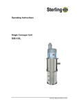
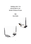
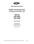
Operation and Installation Instructions
Self-Contained Material Loader
(Compressed Air Venturi Type)
SVL-A, SVL-B, SVL-C, & SVL-D
SVL-B
SVL-A
SVL-C
Bulletin No.: CV6-600
Part No.: 882.00685.00
Effective: 7/2007
SVL-A, SVL-B, SVL-C, & SVL-D Self-Contained Material Loaders - Venturi Style 1 of 49
The manufacturer retains all rights to change the information in these operating instructions at
any time without notice.
We assume no liability for any errors or direct or indirect damage resulting in context with these
operating instructions.
Copying, translation or publication in any form except for personal use of purchaser requires
approval from the manufacturer.
All rights reserved.
SVL-A, SVL-B, SVL-C, & SVL-D Self-Contained Material Loaders - Venturi Style 2 of 49
Shipping Information
Unpacking and Inspection
You should inspect your equipment for possible shipping damage. Thoroughly check
the equipment for any damage that might have occurred in transit, such as broken or
loose wiring and components, loose hardware and mounting screws, etc.
In the Event of Shipping Damage
According to the contract terms and conditions of the Carrier, the responsibility of the
Shipper ends at the time and place of shipment.
Notify the transportation company’s local agent if you discover damage
Hold the damaged goods and packing material for the examining agent’s inspection.
Do not return any goods before the transportation company’s inspection and
authorization.
File a claim with the transportation company. Substantiate the claim by referring to
the agent’s report. A certified copy of our invoice is available upon request. The
original Bill of Lading is attached to our original invoice. If the shipment was prepaid,
write us for a receipted transportation bill.
Advise customer service regarding your wish for assistance and to obtain an RMA
(return material authorization) number.
If the Shipment is Not Complete
Check the packing list as back-ordered items are noted on the packing list. In
addition to the equipment itself, you should have:
.. Bill of lading
.. Packing list
.. Operating and Installation packet
Electrical schematic and panel layout drawings
.. Component instruction manuals (if applicable)
Re-inspect the container and packing material to see if you missed any smaller items
during unpacking.
If the Shipment is Not Correct
If the shipment is not what you ordered, contact the parts and service department
immediately at (262) 641-8610 Have the order number and item number available.
Hold the items until you receive shipping instructions.
Returns
Do not return any damaged or incorrect items until you receive shipping instructions
from the shipping department.
SVL-A, SVL-B, SVL-C, & SVL-D Self-Contained Material Loaders - Venturi Style 3 of 49
Table of Contents
Chapter 1: Safety Instructions ................................................... 6
1-1
1-2
1-3
1-4
How to Use This Manual ............................................................................................. 6
Safety Symbols Used in this Manual .....................................................................6
Explanations and Information...................................................................................... 7
For Your Safety ........................................................................................................... 8
How to Use This Manual .......................................................................................8
Warnings and Precautions ....................................................................................8
Maintenance Responsibility...................................................................................9
Unit Safety................................................................................................................... 9
Chapter 2: Installation.............................................................. 10
2-1
2-2
2-3
2-4
2-5
2-6
General Information................................................................................................... 10
Installing the Material Receiver ................................................................................. 10
Installing the Control Assembly ................................................................................. 10
Connecting the Compressed Air Supply ................................................................... 10
Connecting Material Lines......................................................................................... 10
Electrical Connection................................................................................................. 10
CHAPTER 3: FUNCTIONAL DESCRIPTION............................ 10
3-1
3-2
3-3
Operational Summary ............................................................................................... 10
Method of Functioning............................................................................................... 10
Control Assembly ...................................................................................................... 10
CHAPTER 4: SETUP................................................................. 10
4-1
4-2
4-3
4-4
Preparations .............................................................................................................. 10
Adjusting Compressed Air Flow................................................................................ 10
Setting the Mixing Ratio of the Components (SVL-C Units) ..................................... 10
Basic Setting of the Filling Level in the Conveyor Hopper........................................ 10
CHAPTER 5: MAINTENANCE .................................................. 10
Preparations......................................................................................................................... 10
5-1
Maintenance Intervals ............................................................................................... 10
5-2
Cleaning the Conveying Filter ................................................................................... 10
5-3
Cleaning the Compressed Air Filter .......................................................................... 10
Disassembly ........................................................................................................10
Assembly .............................................................................................................10
5-4 Adjusting the Level Probe............................................................................................ 10
5-4
Troubleshooting......................................................................................................... 10
SVL-A, SVL-B, SVL-C, & SVL-D Self-Contained Material Loaders - Venturi Style 4 of 49
CHAPTER 6: TECHNICAL DATA............................................. 10
* Optional 230 V, AC, PE, 50/60 Hz..................................................................................... 10
6-1 Dimension Sheet ......................................................................................................... 10
6-2 Spare Parts Lists ....................................................................................................... 10
6-3
Quick Start Guide –SVL Self Contained Material Loader.......................................... 10
Technical Assistance................................................................................................. 10
Parts Department ................................................................................................10
Service Department.............................................................................................10
Sales Department................................................................................................10
Contract Department ...........................................................................................10
SVL-A, SVL-B, SVL-C, & SVL-D Self-Contained Material Loaders - Venturi Style 5 of 49
Chapter 1: Safety Instructions
1-1 How to Use This Manual
Use this manual as a guide and reference for installing, operating, and maintaining
your loading system. The purpose is to assist you in applying efficient, proven
techniques that enhance equipment productivity.
This manual covers only light corrective maintenance. No other maintenance should
be undertaken without first contacting a service engineer.
The Functional Description section outlines models covered, standard features, and
safety features. Additional sections within the manual provide instructions for
installation, pre-operational procedures, operation, preventive maintenance, and
corrective maintenance.
The Installation chapter includes required data for receiving, unpacking, inspecting,
and setup of the drying system. We can also provide the assistance of a factorytrained technician to help train your operator(s) for a nominal charge. This section
includes instructions, checks, and adjustments that should be followed before
commencing with operation of the drying system. These instructions are intended to
supplement standard shop procedures performed at shift, daily, and weekly intervals.
The Operation chapter includes a description of electrical and mechanical controls, in
addition to information for operating the equipment safely and efficiently.
The Maintenance chapter is intended to serve as a source of detailed assembly and
disassembly instructions for those areas of the equipment requiring service.
Preventive maintenance sections are included to ensure that your equipment
provides excellent, long service.
The Troubleshooting chapter serves as a guide for identification of most common
problems. Potential problems are listed, along with possible causes and related
solutions.
The Appendix contains technical specifications, drawings, schematics, parts lists,
and available options. A spare parts list with part numbers specific to your machine
is provided with your shipping paperwork package. Refer to this section for a listing
of spare parts for purchase. Have your serial number and model number ready
when ordering.
Safety Symbols Used in this Manual
The following safety alert symbols are used to alert you to potential personal injury
hazards. Obey all safety messages that follow these symbols to avoid possible injury
or death.
SVL-A, SVL-B, SVL-C, & SVL-D Self-Contained Material Loaders - Venturi Style 6 of 49
1-2
DANGER!
DANGER indicates an imminently hazardous situation that, if not
avoided, will result in death or serious injury.
WARNING!
WARNING indicates a potentially hazardous situation or practice
that, if not avoided, could result in death or serious injury.
Caution!
CAUTION indicates a potentially hazardous situation or practice
that, if not avoided, may result in minor or moderate injury or in
property damage.
Explanations and Information
Various terms and designations are used frequently in these operating
instructions to ensure clarity. Therefore, please note that the terms used in the
text are defined as follows:
• Equipment
Equipment can mean an individual unit, a machine, or an installation.
• Operating Personnel
Operating personnel are individuals who are responsible for operating the
equipment. All personnel engaged in the use of the machine should
become familiar with its operation as described in the manual. Each
individual must take responsibility for understanding and following all
safety rules. Operating personnel should be at least 16 years old.
• Operator
The operator of the equipment (production manager, foreman, etc.) is the
person responsible for all production sequences. The operator instructs
the operating personnel on what should be done.
• Operating Instructions
The plant operating instructions describe the interaction of the equipment,
production sequences or methods. The plant operating instructions must
be compiled by the operator of the equipment.
• Equipment Foreman
When several operating personnel work on one machine, the equipment
foreman arranges the order. The equipment foreman must be appointed
by the operator.
• Trained Personnel
Trained personnel are persons who, due to their training, are authorized
to perform the required work.
SVL-A, SVL-B, SVL-C, & SVL-D Self-Contained Material Loaders - Venturi Style 7 of 49
1-3
For Your Safety
How to Use This Manual
•
Please read this manual carefully before initial operation. Understanding the
instructions and equipment will help to avoid injuries as well as damage to
equipment. If you have questions, contact the manufacturer.
•
The operators of this unit must be at least 16 years old.
•
Store this manual near the site of the machine so that it is readily available to
the operators. Faulty operation may lead to accidents!
•
The manual in provided on a CD making it possible to reprint the manual
should an existing copy be damaged or destroyed.
•
Note that, for reasons of brevity, not every possible case of operation or
maintenance can be mentioned in this manual.
•
Be aware of all safety instructions and danger signs on the unit. This will
avoid injuries and damage to material.
•
Prepare precise instructions of the unit using this manual. Faulty operation
can lead to accidents!
Warnings and Precautions
•
Only PROPERLY TRAINED individuals familiar with the information in this
manual should use this equipment.
•
Proper clothing should be worn at all times in order to avoid injuries.
•
Compare the connected loads to those of the main supply to avoid electrical
shock.
•
When using lifting gear, pay close attention to the corresponding instructions
to avoid accidents.
•
Operate this equipment within the local regulations and requirements of the
plant.
•
NEVER modify or alter the unit without the manufacturer’s permission.
•
If the unit has been switched off for safety reasons, it must be protected from
unauthorized use.
•
The unit is exclusively intended for conveying plastic granules and regrind.
Any other usage is not permitted.
•
This unit is not suitable for processing foods.
•
Attachments that are not delivered by the manufacturer must be constructed
according to the safety standard EN 294.
•
Check all lines, hoses, and coupling pieces regularly for leakage and
damage. Any errors must be eliminated immediately.
•
The unit may only be used if all corresponding components have been
properly connected and are in accordance with relevant regulations.
SVL-A, SVL-B, SVL-C, & SVL-D Self-Contained Material Loaders - Venturi Style 8 of 49
•
Observe the safety instructions for the connected units.
Maintenance Responsibility
•
Before beginning maintenance work:
Assign a supervisor.
Inform all other responsible operating personnel.
Turn off the main power supply.(If required)
Set all compressed air lines on the unit at zero pressure.
Repair work should ONLY be done by qualified personnel.
1-4
•
ALWAYS turn off the main supply for all electrical work to avoid risk of death
or injury.
•
NEVER operate on a unit that is partially disassembled. This can cause
serious injuries including amputation and electric shock.
•
In case of functional disturbances, switch the unit off IMMEDIATELY. Any
errors must be eliminated to avoid accidents.
Unit Safety
•
The unit may ONLY be used for conveying plastic granules and regrind on
injection molding machines.
•
NEVER change the settings unless you are able to foresee the
consequences.
•
Use ONLY original manufacturer parts.
•
Follow a regular maintenance schedule.
•
Keep records of all maintenance and repair work.
•
Be aware that electronic subassemblies may be damaged by static
discharge.
•
Before initial operation and at regular intervals, check all electrical
connections for proper fit.
•
NEVER modify sensors without knowing their precise functions.
•
Make sure all plugs are connected properly.
•
Note the carrying capacity of the machine flange.
•
Read the operating manuals of the connected units.
SVL-A, SVL-B, SVL-C, & SVL-D Self-Contained Material Loaders - Venturi Style 9 of 49
Chapter 2: Installation
2-1 General Information
Unpack all parts of the single conveyor unit and make sure that every thing is
available:
•
One material receiver with level sensor
•
Correct type of mounting flange (direct mount, bin mount, or sight glass
mount)
•
Control assembly (one per venturi)
•
One venturi assembly (wand or grinder/take-off)
•
One section of vinyl flexible hose with two hose clamps (per venturi)
•
One length compressed-air poly tubing (per venturi)
•
Operating instructions / customer information packet
Note: The AVL-C comes with two venturi assemblies and two sets of vinyl flexible
hose and four hose clamps.
Figure 2.1: SVL-A Parts
Shown with optional sight glass assembly
SVL-A, SVL-B, SVL-C, & SVL-D Self-Contained Material Loaders - Venturi Style 10 of 49
Figure 2.2: SVL-B Parts
OR
Shown with optional sight glass assembly
Figure 2.3: SVL-C Parts
OR
OR
Shown with optional sight glass assembly
SVL-A, SVL-B, SVL-C, & SVL-D Self-Contained Material Loaders - Venturi Style 11 of 49
2-2 Installing the Material Receiver
The self contained material loader can be installed directly on the processing
machine.
Make sure that all connections are tight so that the conveying performance is not
impaired. The material receiver is equipped with a mounting flange.
Depending on the position, drill the holes for fastening the
conveyor hopper to the processing machine. One of 2
standard bolt patters may be used, sight glass or bin
mounted.(as shown in fig. 2.4)
Mount the material receiver on the processing machine.
Install the vinyl flexible hose on the material receiver inlet
and on the venturi assemblies using the hose clamps that
are supplied.
Make sure all equipment is properly grounded to minimize
static and risk of shock.
Note:
The hopper should not touch any other component.
Figure 2.4
(not to scale)
Sight Glass Mounting Flange
Bin Mount Mounting Flange
SVL-A, SVL-B, SVL-C, & SVL-D Self-Contained Material Loaders - Venturi Style 12 of 49
Sight Glass Mounting Flange
SVL-A, SVL-B, SVL-C, & SVL-D Self-Contained Material Loaders - Venturi Style 13 of 49
Figure 2.5: Flange Mount
Figure 2.6: Sight Glass Mount
Note:
Figure 2.7: Sight Glass Mount
to Digital Dosing Feeder
Figure 2.8: Standard Mount for
SF-1 Feeder
Optional cover adapters may be required.
SVL-A, SVL-B, SVL-C, & SVL-D Self-Contained Material Loaders - Venturi Style 14 of 49
2-3 Installing the Control Assembly
Install the control assembly at a freely accessible site. Check the length of the
connection cable and the length of the supplied hoses to the venturi assemblies.
During installation of equipment, check the length of the air supply lines. In some
cases, longer air supply lines may be required.
Figure 2.9: Control Assembly and Mounting Bracket
Shop Air
To Venturi
Assembly
Control Mounting
Bracket
SVL-A, SVL-B, SVL-C, & SVL-D Self-Contained Material Loaders - Venturi Style 15 of 49
2-4 Connecting the Compressed Air Supply
Before connecting the compressed air supply, check the following:
Check compressed air piping for correct installation and assembly.
Check the fittings, length and quality of the hose connections for
agreement with requirements.
Check all compressed air lines for leakages.
Supply clean, dry (non-lubricated) compressed air with 70-90 psi (5-6 bar)
system pressure.
The air should be free of oil and water.
1. Find the compressed air hose, which has been
supplied.
2. Connect it to the venturi and control assembly.
3. Firmly press the compressed-air hose into each
connecting socket.
4. Connect the control assembly to the compressed air
supply.
5. Set the pressure on the pressure reducer at 70-90 psi
(5-6 bar).
Note:
Unit requires 25 SCFM at 80 psig if continuously run.
Typical air consumption is 8-10 scfm at 80 psig. Max.
input pressure 145 psi (10 bar).
WARNING!
Make sure that the PLANT supply air lines are
large enough to provide required air flow and line
pressure. Failure to provide adequate air flow
and line pressure will result in conveying
performance issues.
Figure 2.10: Venturi Assembly
SVL-A, SVL-B, SVL-C, & SVL-D Self-Contained Material Loaders - Venturi Style 16 of 49
2-5 Connecting Material Lines
Typical SVL Loader installations use flex hose to connect the loader to the
venturi.
Caution!
The material hose should be as straight as possible. Avoid
loops and S-curves in flexible hose. This can hurt conveying
performance.
1. Attach flex hose over the inlet stub of the loader. Secure the hose
with the provided hose clamp. The hose should fit over the inlet stub
at least 1 inch. Position the hose clamp at least ¼ inch from the end
of the inlet.
2. Connect the flex hose to the venturi. From the loader to the venturi,
attach the flex hose in the same manner as described above, being
sure of proper orientation (note arrow on venturi). Reduce flex hose
down to the shortest possible length to avoid wasting compressed air
energy.
Caution!
Flex hose is typically considered a wear item, so it should be
routed or secured in such a way as to make replacement easy.
Flex hose should not be routed close to electrical wires,
especially control signal wires since static electricity, commonly
generated by conveyed material can be discharged to the wires,
fouling electrical operation. If static electricity needs to be
avoided, use grounded flex hose. (Part # - A0565934)
Note: When connecting a vertical feed tube or wand:(used for conveying out of opentop boxes) sufficient slack should be left to allow movement of the feed tube
when the material supply gets low, but “valleys” or droops in the hose should be
avoided.
When connecting a Grinder/Take-off:
(used for conveying from surge bins, silos or granulators) less slack will be
needed, but flex hose is still suggested to allow the hose to be easily
disconnected in the event of trouble. A hose clamp should be installed to prevent
the hose from coming unconnected from the feed tube.
TIP: Rigid tubing like aluminum and stainless steel will last much longer and
provide a straighter path for material flow, usually increasing the loader’s ability
to convey material. When used, rigid tubing should be coupled tightly to prevent
air leaks. It should be routed to minimize bends, and should be connected to the
loader with flex hose to allow quick disconnection of the loader.
SVL-A, SVL-B, SVL-C, & SVL-D Self-Contained Material Loaders - Venturi Style 17 of 49
SVL-C (Two inlet) Installation
Any SVL loader may be equipped for “ratio” or proportioning loading so that two
materials (usually virgin and regrind) may be loaded simultaneously. The
equipment for this function consists of a “Y” tube and coupler that is installed on
the inlet stub of the loader, two controls (one for each component,) a pick-up
device (feed tube), a second venturi and both compressed air lines and material
hoses. If included at the time of original purchase, all of these items will be
included with your SVL. If not included, they may be added later and installed
along with your original system. (See “Spare Parts Lists” for required part
numbers.)
To Install the Ratio Option
Install the “Y” tube using the included “O” ring coupler (see Fig 6.3) onto the inlet
of the SVL-C loader, then connect the flex hoses to the “Y” tube from the two
venturis. Connect the second venturi to the second solenoid package in a
manner similar to the first venturi/solenoid.
Compressed air must be provided to the second filter/regulator in exactly the
same fashion as the first and the second venturi should be joined to the second
solenoid in a similar manner as the first.
Note: Unlike the other types of loading systems that alternately load virgin and then
regrind(back and forth), compressed air conveying systems load the two materials
at the same time, through the “Y” tube conveying material through both venturi
assemblies occurs at the same time as well.
Position the 2 proximity sensors so they are approximately the same height on
the sight glass, then properly adjust the sensors. (See Section 4-3)
Once completed, the installation should provide dual-energized compressed air
solenoids, connected directly to two regulators, so that the material flow through
each venturi may be regulated independently as material flows.
See Section 4-2, Adjusting Compressed Air Flow to properly adjust air flow.
SVL-A, SVL-B, SVL-C, & SVL-D Self-Contained Material Loaders - Venturi Style 18 of 49
2-6 Electrical Connection
The operating voltage is 115 or 230 VAC, AC, PE, 50/60 Hz. Special voltages
available by request.
The connected load is approximately 2 Watts.
The connection is made using a main connector. A separate protection of the
socket is not necessary.
Connect the plug of the sensor cable to the control unit.
Plug the main connector into a corresponding socket.
Make sure all equipment is properly grounded.
WARNING!
Check with the local electricity board for regulations.
SVL-A, SVL-B, SVL-C, & SVL-D Self-Contained Material Loaders - Venturi Style 19 of 49
Chapter 3: Functional Description
3-1
Operational Summary
Once the control switch(s) is turned on, the SVL loader uses a solid state sensor to
determine if material is needed at the material destination (hopper, bin, sight glass,
etc.) If the sensor “sees” material, the loader will remain in an “at rest” mode with its
solenoid de-energized and no compressed air flowing.
Once the material level drops (typically due to process consuming material) and the
SVL sensor no longer “sees” material, the solenoid is energized, turning on the
supply of compressed air to the venturi. The sensor is in a “closed state” to convey
material and an “open state” to signal a high level condition.
The venturi is located near the material supply and creates a vacuum on its inlet by
the rapid rush of compressed air through it. This vacuum pulls on the material
source and begins a flow of material through the venturi. Once inside the venturi, the
material is then ‘pushed’ by the compressed air through the flex hose, towards the
loader.
Once inside the loader, the compressed conveying air is separated from the
conveyed material by a combination of gravity, and the filter located on top of the
loader. Material and dust will stay inside the filter and conveying air will exhaust
through the filter to atmosphere. Unless the material being conveyed is sticky or wet,
the material will fall away from the filter surface and join other loaded material in the
destination hopper or machine throat.
The compressed air energy of the SVL will remain on and material will flow until the
demand sensor of the SVL once again “sees” material. At this time the sensor will
determine that the material level is satisfied and de-energizes the compressed air
solenoid, stopping compressed air and material flow and returning the system to rest,
until the process calls for more material and starts the cycle again.
Note:
The SVL-A unit is designed for clean pelletized material only. The SVL-B and
SVL-C are designed for conveying dust-free plastic granules and regrind
material. Only the SVL-C is capable of conveying two materials.
SVL-A, SVL-B, SVL-C, & SVL-D Self-Contained Material Loaders - Venturi Style 20 of 49
3-2
Method of Functioning
The self-contained venturi loader works according to the
Venturi Principle. An external compressed air supply is
needed to provide the source of compressed air.
A venturi device (A) is integrated in the venturi assembly.
The venturi creates a vacuum in the lower part of the tube
(C) and then conveys the material into the conveyor
hopper using pressurized air in the upper part (B). In the
hopper loader, the material is separated from the air.
The filling level of material receiver is monitored and
controlled by a level sensor located on the sight glass (or
on a flange) of the receiver.
Figure 3.1: Venturi Assembly
SVL-A, SVL-B, SVL-C, & SVL-D Self-Contained Material Loaders - Venturi Style 21 of 49
3-3 Control Assembly
A. The unit is switched ON and OFF at the control.
B. At the regulator, the operating pressure is adjusted. A
filter/separator is integrated into the control.
C. Regularly inspect the compressed air filter to make sure that it is
clean and functioning properly. Clean or replace this filter as
needed. For information, see Section 5: Maintenance.
Figure 3.2: Control and Regulator Unit
Filter Regulator
pressure adjustment
Control mounting bracket
Plant Air Connection
Supply pressure gauge
Solenoid Valve
Capacitive material
demand sensor with quick
connect wiring
16.4 ft (5 meters)
sensor cable
On/Off switch
Main power cord
Control Mounting
Bracket
SVL-A, SVL-B, SVL-C, & SVL-D Self-Contained Material Loaders - Venturi Style 22 of 49
Chapter 4: Setup
4-1
Preparations
Check to see if the venturi assembly is inserted in the material to be
conveyed.
Verify compressed air connections are properly installed.
Switch the compressed air supply ON at the compressed air source.
Check pressure of air supply at the control assembly.
Make sure unit and control are properly grounded.
Switch the conveyor unit electrical switch ON at the control and maintenance
unit.
The material loader should now convey until the conveyor hopper is filled up to
the level sensor.
4-2
Adjusting Compressed Air Flow
The SVL is equipped with a compressed air filter/regulator that will determine the
amount of air that flows to the venturi at the material source. This air flow will
determine how much material will be transferred and how fast your process will
be replenished with material, with each loading sequence.
Adjusting the air setting: It is best to adjust the air setting to its lowest possible
level in order to conserve compressed air energy.
Parameters such as distance, the number of material line bends, the flow
characteristics of the material and vertical rises in the flex hose all play a part in
finding the proper setting. Ultimately, trial and error settings over several loading
sequences will work best to determine the right air level. Too low of a setting
may not move material effectively enough to satisfy demands cycle after cycle.
Too much air will waste energy and cause the filter on the SVL to prematurely
blind in an attempt to evacuate excess air. Refer to the gauge on the regulator
and adjust the air to the lowest possible setting that assures reliable material
transfer.
Note: Unit requires 25 SCFM at 80 PSIG (5-6 bar) if continuously run. Typical air
consumption is 8-10 SCFM @ 80 PSIG.
Adjusting air settings for ratio units: Ratio units have two controls and
compressed air settings to consider. Usually one is dedicated to virgin material
and the other, regrind material. Both material paths terminate into the “Y” tube at
the SVL loader inlet so care must be taken to adjust in consideration of the other.
SVL-C (Two Inlet) Operation. If the goal of your system is to evacuate a
granulator of regrind in the most effective manner, the regulator should be
SVL-A, SVL-B, SVL-C, & SVL-D Self-Contained Material Loaders - Venturi Style 23 of 49
adjusted first for optimum flow, as described above. Since regrind material is
typically more difficult to load than virgin material, it will take more compressed
air (a higher setting on the regulator) than virgin material. Once regrind is
adjusted, then the virgin material flow should be adjusted. Notice the flow of
material through the flex hose as both are loaded. The virgin is likely to flow
much stronger than the regrind and may actually choke off the regrind flow,
requiring new settings to balance out the flows to your needs. Keep in mind that
distances, bends, etc. all play a part in effective compressed air settings, so
continue to adjust both levels until satisfactory loading performance is achieved
for both materials.
Note:
4-3
The SVL compressed air material loader with ratio capability is not intended
to be a blending or metering device for two materials. It can only create air flow
that will allow the conveyance of material to your process. Expectations of any
precision in the loading process will not be achieved.
Setting the Mixing Ratio of the Components (SVL-C Units)
The mixing ratio of the components is adjusted at the regulators. By changing
the regulator pressure of each material, you will adjust the rate at which each
material is conveyed into the conveyor hopper. This will determine the ratio of
two materials entering a conveyor hopper.
Note:
The adjustment of the regulator will vary according to the material, flow
properties, particle size and conveying distance. The ratio of each material is
just an “observed” ratio and there is no guarantee of accurate ratio percentages.
SVL-A, SVL-B, SVL-C, & SVL-D Self-Contained Material Loaders - Venturi Style 24 of 49
4-4
Basic Setting of the Filling Level in the Conveyor Hopper
The filling level in the conveyor hopper is mainly determined by the level sensor.
Figure 4.1: Conveyor Hopper
Function and features:
• Capacitive level switch for monitoring and dry bulk material, preferably plastic granulates.
• Automatic adjustment to the medium to be detected by means of programming pushbutton.
• The sensing face is rated for temperatures up to 110°C and can be mounted in direct contact
with the sight glass (without air gap).
Mounting:
Mount the level switch as shown:
Electrical Connection:
Disconnect the installation from power. Connect the unit
(see type label).
Operation:
Adjust the sensor. To do so, press the programming
pushbutton with a blunt object.
SVL-A, SVL-B, SVL-C, & SVL-D Self-Contained Material Loaders - Venturi Style 25 of 49
Programming:
Overview of the modes and their basic functions:
•
Operating mode: Normal operating mode. In this mode all normal sensor functions are
active.
•
Adjustment mode: Setting of the switching threshold by empty and full adjustment.
•
Locking mode: Locking and unlocking of the unit possible to avoid tampering.
Empty adjustment
The unit must be adjusted after installation in the empty tank (empty adjustment). The tank can
be considered to be "empty" when the medium to be detected is a minimum of 20mm (0.9
inches) away from the active zone. If the sensor detects a medium after adjustment, its
switching status changes.
Note:
The sensor is operational just with empty adjustment. However, it is
recommended to carry out a "full adjustment" with the active zone being
completely covered after empty adjustment. On the basis of the values for the
empty state/full state the internal microprocessor determines the optimum position
of the switching thresholds between the two states. Using both adjustment criteria
(empty and full adjustment) results in the maximum operational reliability for the
application. For empty adjustment the internal microprocessor generates 2 values.
The first value corresponds to the sensor signal measured in the empty state. The second value
is an assumed measured value for the full state. It is calculated from the just measured empty
state and a factory signal preset. For full adjustment this second value is replaced by a real
measured value.
SVL-A, SVL-B, SVL-C, & SVL-D Self-Contained Material Loaders - Venturi Style 26 of 49
Full adjustment
After empty adjustment the full state is to be achieved, if possible, so that the unit switches.
The full adjustment can be repeated as often as you like. The stored value for the empty state is
not overwritten by the full adjustment. After a new empty adjustment both values are
automatically set again, the values last defined are overwritten. Therefore always carry out the
empty adjustment first, then, if necessary, the full adjustment!
Locking
The stored adjustment values can be protected against unauthorized programming as follows
(factory setting: not locked):
When the programming pushbutton is released the unit is locked and all programming functions
are inactive. The unit returns to the operating mode.
If this operation starts from the locked state, the green LED does not react for 10s. After 10s the
unit is unlocked (see "Unlocking").
SVL-A, SVL-B, SVL-C, & SVL-D Self-Contained Material Loaders - Venturi Style 27 of 49
Unlocking
When the programming pushbutton is released the unit is unlocked and all programming
functions are active again.
Error messages
If empty or full adjustment cannot be made, the red LED flashes quickly at about 8Hz after the
adjustment attempt (adjustment error).
To delete this error message press the programming pushbutton once or power off and then
power on again. The measured values successfully read so far remain unchanged.
Possible reasons for an error message:
•
The signal difference between the empty and full state is too small (e.g. empty and full
adjustment without sufficient change of the level).
•
The signal change between the empty and full state is in the wrong order (e.g. empty
adjustment in the full state and then full adjustment in the empty state).
•
Empty adjustment outside the operating range (e.g. empty adjustment in case of direct
contact with an electrically grounded medium, e.g. if the active zone is immersed in
water).
Help: Avoid the above-mentioned errors and repeat the adjustment for error correction.
Further faults:
•
Electronic fault or sensing zone of the unit damaged
•
Internal fault (can only be deleted by power off and then power on again, hardware
reset).
SVL-A, SVL-B, SVL-C, & SVL-D Self-Contained Material Loaders - Venturi Style 28 of 49
Set-up / Operation:
Check the safe functioning of the unit. To do so, bring about a sensor response by taking
suitable measures.
Display by LEDs:
LED green
Flashes slowly (1Hz): adjustment mode empty
adjustment
LED yellow
OFF: switching output disabled
ON: switching output enabled
LED red
Flashes quickly (8Hz): adjustment error, internal fault
Flashes slowly (1Hz): close to reaching the switching
The red LED becomes active for a short time during the change between "medium not present"
and "medium present" (flashes at 1Hz) if the medium is close to reaching the switching
threshold. This can occur in particular if the level changes very slowly and is no error message
meaning a fault in the unit.
The operation of the level switch is maintenance-free. For a correct function ensure the sensing
face and the open space should be kept free of deposits and foreign bodies, particularly for
mounting with the sensing face showing upwards.
SVL-A, SVL-B, SVL-C, & SVL-D Self-Contained Material Loaders - Venturi Style 29 of 49
Chapter 5: Maintenance
Preparations
Please observe the maintenance intervals.
Before starting maintenance work, clean the equipment of oil, fuel or
lubricants.
Ensure that materials and incidentals required for operation as well as spare
parts are disposed of properly and in an environmentally sound manner.
Use only original manufacturer spare parts.
Keep record of all maintenance and repair procedures.
Caution!
5-1
Disconnect the equipment from main electrical supply before
starting maintenance procedures to ensure that it cannot be
switched on unintentionally. Depressurize all compressed air
piping of the equipment before starting maintenance work.
Maintenance Intervals
Daily:
Check the filter for obstructions or damage when doing a material change.
Check the setting of the pressure regulator.
Empty the water separator.
Check danger signs on the unit for legibility and completeness.
Check for worn tubing or loose electrical connections.
Weekly:
Clean the cartridge filter and screen (depending on accumulation of dust).
Blow out the filter from the inside using compressed air.
Check the electrical connections for proper functioning.
Every 3 Drain the compressed air filter trap.
months:
Check all electrical and mechanical connections.
Replace filter (depending on accumulation of dust and condition of filter).
Note: The maintenance intervals provided are average values. The maintenance
intervals might be adjusted due to your individual process conditions.
Replace/repair components as required.
SVL-A, SVL-B, SVL-C, & SVL-D Self-Contained Material Loaders - Venturi Style 30 of 49
5-2
Cleaning the Conveying Filter
WARNING!
Disconnect power air sources. Always disconnect the main power source
and compressed air source before removing the filter. This prevents the
loader from starting during servicing, which could cause injury from flying
debris.
Caution!
Wear eye protection. We recommend that you use vacuum air
for cleaning filters and other parts of this equipment. If you use
compressed air to clean the equipment, you must wear eye
protection and observe all OSHA and other safety regulations
pertaining to the use of compressed air.
The filter module atop the SVL loader must be cleaned periodically to assure that
compressed air evacuation from the loader is efficient. If this filter becomes clogged
the conveying air will seek an alternate escape route, possibly forcing its way out
through crevices in the receiving hopper or elsewhere. Loading performance could
be hampered by the resistance that the filter gives to air (and material) flow.
1. Remove the filter. The filter module is friction fitted to the top of the
loader body and may be easily removed by hand, without tools.
2. Inspect the filter carefully. Depending upon the material that was
conveyed, the filter may only require a brief wipe-out of the inside to
remove residual material fines and dust. Always check for holes that
could allow the passage of fines or dust to the loader motor. Replace
the filter if it is damaged, excessively worn or too clogged with material
dust. Do not attempt to repair a damaged filter. Replace the entire filter
if the rubber seal is damaged or excessively worn.
3. Clean the filter. For dusty material or color changes, the filter should
be wiped out and then vacuumed. We recommend that you vacuum the
filter surfaces. If you use compressed air, you must wear eye protection
and follow all safety regulations pertaining to cleaning equipment with
compressed air. Do not attempt to repair a damaged filter.
Caution!
A SVL filter that is worn to the extent that it does not provide a
good seal around the base may not grip the top of the loader
sufficiently and could fall off during use. This is a hazard to
those below/near the loader. The filter should be replaced so
that a good, secure fit is achieved each time the filter is installed
on the loader.
SVL-A, SVL-B, SVL-C, & SVL-D Self-Contained Material Loaders - Venturi Style 31 of 49
4. Install/reinstall the filter. Firmly press down on the filter to make sure a
good seal is provided around the entire perimeter of the filter module.
The filter should fit evenly on the top of the loader body.
Figure 5.1: SVL-A
5-3
Figure 5.2: SVL-B
Cleaning the Compressed Air Filter
The compressed air supply to the loader is provided with a moisture trap to prevent
troublesome moisture, contained in the air, from touching your material. The filter
bowl should be drained regularly to remove this moisture.
To remove moisture:
1. Open the filter bowl drain. Turn the knob on the bottom of the
filter bowl counterclockwise. Leave the drain open until all moisture
has been removed.
2. Close the filter bowl drain. Turn the knob clockwise to close the
drain.
WARNING!
Switch the unit OFF. Disconnect the main electrical plug.
SVL-A, SVL-B, SVL-C, & SVL-D Self-Contained Material Loaders - Venturi Style 32 of 49
Disassembly
1. Remove the filter cartridge (A).
2. Blow out the filter cartridge (A) from the inside out using compressed air or
replace the filter.
3. Open the toggle-type fastener (SVL-B, SVL-C models) (C) and fold the
hopper lid upward.
4. Check the screen (B) within the lid for material residue.
5. Clean the screen (B) using compressed air.
Assembly
1. Clean the hopper loader using a vacuum cleaner.
2. Replace the cover gasket/screens (SVL-B, SVL-C.)
3. Close the hopper lid (SVL-B, SVL-C.)
4. Close the toggle-type fastener (SVL-B, SVL-C.)
5. Assemble the filter cartridge.
5-4 Adjusting the Level Probe
See Chapter 4: Setup, to properly adjust air flow.
SVL-A, SVL-B, SVL-C, & SVL-D Self-Contained Material Loaders - Venturi Style 33 of 49
5-4
Troubleshooting
PROBLEM
REMEDY (See Test Steps Below)
The unit is not conveying and is not
active.
A, B, G, H
The unit is not conveying; the
compressed air valve is activated
when the device is switched on.
C, D, E, F, N
The unit is not conveying; the
compressed air is flowing through
the valve.
C, D, E, F, I, J, K,N
The unit is overfilled.
G, L, M
The unit is not filling properly.
C, D, E, F, I, J, K, L,N
Test steps:
A - Make sure the unit is switched ON.
B - Make sure the unit is plugged in and the proper voltage is present.
C - Make sure sufficient compressed air is available 70-90 psi (5-6 bar).
D - Make sure the venturi assembly is inserted in the material.
E - Make sure the compressed air hose is properly connected to the venturi assembly.
F - Make sure the compressed air hose (incoming supply line) is properly connected to
the control solenoid.
G - Make sure the level sensor is properly adjusted.
H - Make sure the cable of the level sensor is properly connected.
I - Make sure the filter is not clogged.
J - Make sure the screen is not clogged.
K - Make sure the vinyl flexible hose is properly connected.
L - Make sure the compressed air supply is properly adjusted.
M - Make sure the level sensor is not defective.
N - Check source of material.
SVL-A, SVL-B, SVL-C, & SVL-D Self-Contained Material Loaders - Venturi Style 34 of 49
-Notes-
SVL-A, SVL-B, SVL-C, & SVL-D Self-Contained Material Loaders - Venturi Style 35 of 49
Chapter 6: Technical Data
Maximum througput:
475 lbs/h (149.7 kg/hr)
Weight:
Approx. 6.61 lbs. (3 kg)
Operating voltage:*
115 V, AC, PE, 50/60 Hz (standard)
Special voltage on request
Connected load:
Approx. 2 W
Total noise level:
< 75 dB (A)
Compressed air supply:
70-90 psi (5-6 bar)
Compressed air consumption:
25.9 scfm at 80 psig (continuous 100% non-stop
operation)
8-10 scfm at 80 psig based on 30% duty cycle for
intermittent use (most applications).
-42” H2O (-11 kPa)
Compressed air consumption
typical:
Vacuum Performance (at 80
psig and full flow):
Max. product temperature:
176°F (80 °C)
* Optional 230 V, AC, PE, 50/60 Hz
SVL-A, SVL-B, SVL-C, & SVL-D Self-Contained Material Loaders - Venturi Style 36 of 49
6-1 Dimension Sheet
Figure 6.1: SVL-A
SVL-A, SVL-B, SVL-C, & SVL-D Self-Contained Material Loaders - Venturi Style 37 of 49
Figure 6.2: SVL-B
Dimensions and data are not binding. All dimensions are in inches. All data are subject to change.
SVL-A, SVL-B, SVL-C, & SVL-D Self-Contained Material Loaders - Venturi Style 38 of 49
Figure 6.3: SVL-C
Dimensions and data are not binding. All dimensions are in inches. All data are subject to change.
SVL-A, SVL-B, SVL-C, & SVL-D Self-Contained Material Loaders - Venturi Style 39 of 49
Figure 6.4: SVL-D
SVL-A, SVL-B, SVL-C, & SVL-D Self-Contained Material Loaders - Venturi Style 40 of 49
6-2
Spare Parts Lists
Figure 6.5: SVL-A
.
SVL-A, SVL-B, SVL-C, & SVL-D Self-Contained Material Loaders - Venturi Style 41 of 49
Figure 6.6: SVL-B
SVL-A, SVL-B, SVL-C, & SVL-D Self-Contained Material Loaders - Venturi Style 42 of 49
Figure 6.7: SVL-C
SVL-A, SVL-B, SVL-C, & SVL-D Self-Contained Material Loaders - Venturi Style 43 of 49
Figure 6.8: Control Assembly
Control Mounting
Bracket
SVL-A, SVL-B, SVL-C, & SVL-D Self-Contained Material Loaders - Venturi Style 44 of 49
Figure 6.9: Wand Assembly
SVL-A, SVL-B, SVL-C, & SVL-D Self-Contained Material Loaders - Venturi Style 45 of 49
Figure 6.10: Take-Off Wand Assembly
SVL-A, SVL-B, SVL-C, & SVL-D Self-Contained Material Loaders - Venturi Style 46 of 49
6-3
Quick Start Guide –SVL Self Contained Material Loader
Unpack all parts. Check for the following:
Material receiver with level sensor and mounting
option
Control Assembly(s)
Venturi assembly(s)
Vinyl flexible hose(s)
Compressed air hose(s)
Operating instructions (on CD)
Mount the material receiver using the flange provided on its base.
Mount the control assembly at a location that is readily accessible. Make
sure that the compressed air hose and level sensor cable are long
enough to reach the control assembly.
Connect the compressed air supply from the control assembly to the
fitting located on the material pick up wand using the poly tubing supplied
with the equipment.
Connect shop compressed air to the regulator on the control assembly.
The compressed air connection must be 70-90 psi (5-6 bar). (Minimum 8
SCFM, maximum 25.9 SCFM)
Plug the control assembly into the main power socket. Make sure that
the correct voltage is being used.
Adjust the level sensor to sense the material that is being conveyed into
the conveying hopper.
Maintain the unit as stated in Chapter 5 of this manual.
Convey material
SVL-A, SVL-B, SVL-C, & SVL-D Self-Contained Material Loaders - Venturi Style 47 of 49
Technical Assistance
Parts Department
Call toll-free 7am–5pm CST [800] 423-3183 or [262] 641-8610, Fax [262] 641-8653
The ACS Customer Service Group will provide your company with genuine OEM
quality parts manufactured to engineering design specifications, which will maximize
your equipment’s performance and efficiency. To assist in expediting your phone or
fax order, please have the model and serial number of your unit when you contact
us. A customer replacement parts list is included in this manual for your
convenience. ACS welcomes inquiries on all your parts needs and is dedicated to
providing excellent customer service.
Service Department
Call toll-free 8am–5pm CST [262] 641-8610 or call [800] 423-3183
Emergencies after 5pm CST, call [847] 439-5655
We have a qualified service department ready to help. Service contracts are
available for most products.
Sales Department
Call [262] 641-8610 Monday–Friday, 8am–5pm CST
Our products are sold by a worldwide network of independent sales representatives.
Contact our Sales Department for the name of the sales representative nearest you.
Contract Department
Call [262] 641-8610 Monday–Friday, 8am–5pm CST
Let us install your system. The Contract Department offers any or all of these
services: project planning; system packages including drawings; equipment, labor,
and construction materials; and union or non-union installations.
SVL-A, SVL-B, SVL-C, & SVL-D Self-Contained Material Loaders - Venturi Style 48 of 49
SVL-A, SVL-B, SVL-C, & SVL-D Self-Contained Material Loaders - Venturi Style 49 of 49