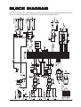
1
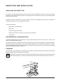
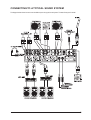
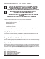
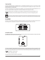
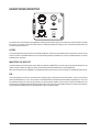
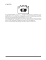
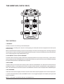
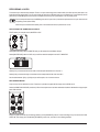
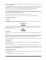
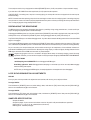
1
IMPORTANT
Please read this manual carefully before using
your mixer for the first time.
© Harman International Industries Ltd. 2005
All rights reserved
Parts of the design of this product may be protected by worldwide patents.
Part No. ZM0321-01
Soundcraft is a trading division of Harman International Industries Ltd. Information in this manual
is subject to change without notice and does not represent a commitment on the part of the
vendor. Soundcraft shall not be liable for any loss or damage whatsoever arising from the use of
information or any error contained in this manual.
No part of this manual may be reproduced, stored in a retrieval system, or transmitted, in any
form or by any means, electronic, electrical, mechanical, optical, chemical, including photocopying
and recording, for any purpose without the express written permission of Soundcraft.
Harman International Industries Limited
Cranborne House
Cranborne Road
POTTERS BAR
Hertfordshire
EN6 3JN
UK
Tel:
+44 (0)1707 665000
Fax: +44 (0)1707 660742
http://www.ureidj.com
2
Contents
IMPORTANT SAFETY INSTRUCTIONS
SAFETY SYMBOL GUIDE
4
6
INSTALLATION
9
GENERAL PRECAUTIONS
MAINS INSTALLATION
INITIAL WIRING CONSIDERATIONS
AUDIO WIRING
SHIELDING
WORKING SAFELY WITH SOUND
POINTS TO REMEMBER
INSPECTION AND INSTALLATION
CONNECTING TO A TYPICAL SOUND SYSTEM
MAKING ADJUSTMENTS AND FITTING SPARES
9
9
10
10
10
10
11
12
13
14
DESCRIPTION
16
TOP PANEL
REAR CONNECTOR PANEL
FRONT PANEL
16
18
19
OPERATION
20
GETTING STARTED
MIC / LINE INPUT
CHANNELS 1 & 2
FX SEND & RETURN / AUX
MASTER / BOOTH OUTPUT
X-FADER
HEADPHONE MONITOR
THE SAMPLER (1601S ONLY)
20
20
22
24
26
27
28
30
BLOCK DIAGRAM
35
CONNECTING LEADS
36
TROUBLESHOOTING
37
SPECIFICATIONS
38
WARRANTY
39
GLOSSARY
40
3
IMPORTANT SAFETY INSTRUCTIONS
Read these instructions.
Keep these instructions.
Heed all warnings.
Follow all instructions.
Do not use this apparatus near water.
Clean only with a dry cloth.
Do not block any ventilation openings. Install in accordance with the manufacturer’s instructions.
Do not install near any heat sources such as radiators, heat registers, stoves, or other apparatus (including
amplifiers) that produce heat.
Do not defeat the safety purpose of a polarised or grounding type plug. A polarised plug has two blades with one
wider than the other. A grounding type plug has two blades and a third grounding prong. The wide blade or the
third prong are provided for your safety. If the provided plug does not fit into your outlet, consult an electrician for
replacement of the obsolete outlet
Protect the power cord from being walked on or pinched particularly at plugs, convenience receptacles and the
point where they exit from the apparatus.
Only use attachments/accessories specified by the manufacturer.
Use only with the cart, stand, tripod, bracket or table specified by the manufacturer, or sold with the apparatus.
When a cart is used, use caution when moving the cart/apparatus combination to avoid injury from tip-over.
Unplug this apparatus during lightning storms or when unused for long periods of time.
Refer all servicing to qualified service personnel. Servicing is required when the apparatus has been damaged
in any way, such as power-supply cord or plug is damaged, liquid has been spilled or objects fallen into the
apparatus, the apparatus has been exposed to rain or moisture, does not operate normally, or has been dropped.
4
Note: It is recommended that all maintenance and service on the product should be carried out by Soundcraft or its
authorised agents. Soundcraft cannot accept any liability whatsoever for any loss or damage caused by service,
maintenance or repair by unauthorised personnel.
WARNING: To reduce the risk of fire or electric shock, do not expose this apparatus to rain or moisture.
Do not expose the apparatus to dripping or splashing and do not place objects filled with liquids, such as vases, on
the apparatus.
No naked flame sources, such as lighted candles, should be placed on the apparatus.
Ventilation should not be impeded by covering the ventilation openings with items such as newspapers, table
cloths, curtains etc.
THIS APPARATUS MUST BE EARTHED. Under no circumstances should the safety earth be disconnected from
the mains lead.
The mains supply disconnect device is the mains plug. It must remain accessible so as to be readily operable when
the apparatus is in use.
If any part of the mains cord set is damaged, the complete cord set should be replaced. The following information
is for reference only.
The wires in the mains lead are coloured in accordance with the following code:
Earth (Ground):
Green and Yellow (US - Green/Yellow)
Neutral:
Blue (US - White)
Live (Hot):
Brown (US - Black)
As the colours of the wires in the mains lead may not correspond with the coloured markings identifying the terminals
in your plug, proceed as follows:
The wire which is coloured Green and Yellow must be connected to the terminal in the plug which is
marked with the letter E or by the earth symbol.
The wire which is coloured Blue must be connected to the terminal in the plug which is marked with the
letter N
The wire which is coloured Brown must be connected to the terminal in the plug which is marked with the
letter L
Ensure that these colour codes are followed carefully in the event of the plug being changed
This unit is capable of operating over a range of mains voltages as marked on the rear panel.
NOTE: This equipment has been tested and found to comply with the limits for a Class A digital device, pursuant to
Part 15 of the FCC Rules. These limits are designed to provide reasonable protection against harmful interference
when the equipment is operated in a commercial environment. This equipment generates, uses and can radiate
radio frequency energy and, if not installed and used in accordance with the instruction manual, may cause harmful
interference to radio communications. Operation of this equipment in a residential area is likely to cause harmful
interference in which case the user will be required to correct the interference at his own expense.
This Class A digital apparatus meets the requirements of the Canadian Interference-Causing Equipment Regulations.
Cet appareil numérique de la Classe A respecte toutes les exigences du Règlement sur le matériel brouilleur du
Canada.
5
For your own safety and to avoid invalidation of the
warranty please read this section carefully.
SAFETY SYMBOL GUIDE
For your own safety and to avoid invalidation of the warranty all text marked with these symbols
should be read carefully.
WARNINGS
The lightning flash with arr
arrowhead
owhead symbol, is
esence of unalertt the user to the pr
presence
intended to aler
insulated “danger
ous voltage” within the pr
oduct’s
“dangerous
product’s
enclosur
e that may be of suf
ficient magnitude to
enclosure
sufficient
constitute a risk of electric shock to persons.
CAUTIONS
The exclamation point within an equilateral triangle
is intended to aler
esence of
alertt the user to the pr
presence
impor
tant operating and maintenance (servicing)
important
instructions in the literatur
e accompanying the
literature
appliance.
NOTES
Contain impor
tant infor
mation and useful tips on
important
information
the operation of your equipment.
HEADPHONES SAFETY WARNING
Contain impor
tant infor
mation and useful tips on
important
information
headphone outputs and monitoring levels.
Recommended Headphone Impedance >= 200 Ohms.
TIP
Contains a useful “tip” on how to get the best out
of your equipment.
6
INTR
ODUCTION
INTRODUCTION
Thank you for purchasing a UREI 16XX series digital DJ mixing desk.
Digital technology is revolutionizing the world around us: digital audio, digital video, digital television, digital radio -in all these fields
digital technology is expanding our ideas of what is possible. Digital Signal Processing has already delivered many of the technological
innovations in audio which have driven the recording and re-mixing of dance music. Sampling and effects processing are major
parts of the re-mix process and many styles of dance music just wouldn’t have evolved without them. Up until now, the DJ has made
do with the limitations of analogue technology in the live arena.
Now, UREI by Soundcraft bring the DJ a range of digital mixers for the performance DJ, with operating ergonomics and facilities that
ONLY digital can bring you, and which no other products available today can offer. Configurability, audio performance and special
effect integration are well served by digital technology.
The 1601 and 1601S are just the first of the digital innovations which UREI by Soundcraft are developing to bring the benefits of
digital technology to live mixing. As the 16XX series Digital DJ Mixing System expands, other exciting new methods of processing
the sound in live mixing will be added, as the DJ and the UREI mixer become one.
Introducing the 16XX series. Welcome to the future of DJ mixing.
Registering Your Mixer
Please take this opportunity to register the purchase of your mixer with Urei By Soundcraft. You can do this by filling in the pre-paid
postcard included in the packaging, or by going online to www.ureidj.com/registration.
7
8
INST
ALLA
TION
INSTALLA
ALLATION
The 1601S and 1601 are ruggedly constructed with the highest quality components. As such, they should provide years of trouble
free use with normal care. All parts used are conservatively rated for their application, and workmanship meets UREI by Soundcraft’s
rigid standard.
NO SPECIAL PREVENTIVE MAINTENANCE IS REQUIRED, AND (WITH THE
EXCEPTION OF THE PRE-TRIM ATTENUATORS) THERE ARE NO INTERNAL
SERVICE ADJUSTMENTS.
GENERAL PRECAUTIONS
Avoid storing or using the mixing console in conditions of excessive heat or cold, or in positions where it is likely to be subject to
vibration, dust or moisture. Do not use any liquids to clean the fascia of the unit: a soft dry cloth is ideal.
Avoid using the console close to strong sources of electromagnetic radiation (e.g. video monitors, high-power electric cabling): this
may cause degradation of the audio quality due to induced voltages in connecting leads and chassis.
Caution! In all cases, refer servicing to qualified personnel.
Handling and Transport
The console is supplied in a strong carton. If it is necessary to move it any distance after installation it is recommended that this
packing is used to protect it. Be sure to disconnect all cabling before moving. If the console is to be regularly moved we recommend
that it is installed in a foam lined flightcase. At all times avoid applying excessive force to any knobs, switches or connectors.
Power Cable
Always use the power supply cable supplied with the mixer: the use of alternative cables may cause damage and voids the warranty.
Warning ! In the event of an electrical storm, or large mains voltage fluctuations,
immediately unplug from the mains.
Signal Levels
It is important to supply the correct input levels to the console, otherwise signal to noise ratio or distortion performance may be
degraded; and in extreme cases, damage to the internal circuitry may result. Likewise, on all balanced inputs avoid sources with
large common mode DC, AC or RF voltages, as these will reduce the available signal range on the inputs. Note that OdBu =0.775V
RMS.
Refer to the Specifications section for details of input and output levels.
MAINS INSTALLATION
General Wiring Procedures
To take full advantage of the excellent signal to noise ratio and low distortion of Soundcraft consoles, care must be taken to ensure
that incorrect installation and wiring does not degrade the performance of the desk. Hum, buzz, instability and Radio Frequency
interference can usually be traced to earth loops and inferior earthing systems. In some areas, especially heavily industrial areas,
the incoming mains earth will not be adequate and a separate technical earth for all the audio equipment must be supplied. However,
check with your local electricity supply company to ensure that safety regulations are not infringed or negated.
The successful, hum free, installation of a system requires forethought, and the establishment of a set of ground rules, which must
be consistently adhered to at all stages of installation.
9
INITIAL WIRING CONSIDERATIONS
For optimum performance, it is essential for the earthing system to be clean and noise free, as all signals are referenced to this
earth. A central point should be decided on for the main earth point system, and all earths should be 'star fed' from this point. It is
common electrical practice to `daisy chain' the earths to all electrical outlets but this method is unsuitable for audio installations. The
preferred method is to run an individual earth wire from each outlet, back to the system star point to provide a safety earth screen
reference for each piece of equipment. A separate earth wire should also be run from each equipment rack and area, to the star
point. This may or may not be used depending on circumstances, but it is easier to install in the first place, than later when problems
arise. The location of the star point should be a convenient, easily accessible place, preferably at the rear of the console or in the
main equipment rack.
Install separate 'clean' and 'dirty' mains outlets, wired individually back to the incoming mains distribution box. Use the 'clean' supply
for all audio equipment and the `dirty' supply for all lighting, etc. Never mix the two systems.
If necessary, to provide sufficient isolation from mains borne interference on the booth output, install an isolating transformer. This
should be provided with a Faraday Shield which must be connected with earth.
Never locate the incoming mains distribution box near audio equipment, especially tape recorders, which are very sensitive to
electromagnetic fields.
Ensure that all equipment racks are connected to earth, via a separate wire back to the star point.
Equipment which has unbalanced inputs and outputs may need to be isolated from the rack to prevent earth loops.
AUDIO WIRING
Having provided all equipment with power and earthing connections, consideration must be given to the method of providing audio
interconnection and adequate screening of those interconnections. This must be done in a logical sequence to avoid problems and
assist in the localisation of problem equipment.
Connect the Main or Booth system to the console and check for any hum, buzz, or RFI. Only when you are satisfied with the
quietness of the console and the PA system should you proceed with the next step.
Connect decks or CD players, FX and sends one at a time, checking and isolating any connection which degrades performance.
Connect all other peripheral devices.
Connect all microphone lines.
By following this sequence much time and future trouble will be saved, and the result will be a quiet, stable system.
SHIELDING
Audio equipment is supplied with a variety of input and output configurations, which must be taken into consideration when deciding
where the screen connections should be made. There are three sources of unwanted signal being impressed on the screen, which
are as follows:
Extraneous electrostatic or electromagnetic fields.
Noise and interference on the earth line.
Capacitive coupling between the screen and signal wires.
To minimise the adverse affects of the unwanted coupling to the signal wires, it is important that the screen is connected at one end
only, i.e. the screen must not carry any signal current. Any signal on the wires within the screen will be capacitively coupled to the
screen. This current will ultimately be returned to the source of the signal, either directly, if the screen is connected at the signal
source end, or indirectly via the earthing system, if the signal is connected at the signal destination end. The indirect connection will
cause an increase in high frequency cross-talk, and should be avoided wherever possible.
Therefore, in general, always connect the shield only at the signal source end. In high RF areas, the screen can also be connected
to earth via a 0.01 mF capacitor. This will present a short circuit at RF frequencies, thus lowering the effective shield impedance to
ground. However, at low audio frequencies the capacitor will effectively be an open circuit and thus not cause an earth loop problem.
10
POINTS TO REMEMBER
In all cases, use good quality twin screened audio cable. Check for instability at the output.
Always connect both conductors at both ends, and ensure that the screen is only connected at one end.
Do not disconnect the mains earth from each piece of equipment. This is needed to provide both safety and screen returns to the
system star point.
Equipment which has balanced inputs and outputs may need to be electrically isolated from the equipment rack and/or other
equipment, to avoid earth loops.
It is important to remember that all equipment which is connected to the mains is a potential source of hum and interference and may
radiate both electrostatic or electromagnetic radiation. In addition, the mains will also act as a carrier for many forms of RF interference
generated by electric motors, air-conditioning units, thyristor light dimmers etc. Unless the earth system is clean, all attempts to
improve hum noise levels will be futile. In extreme cases there will be no alternative but to provide a completely separate and
independent `technical earth' to replace the incoming 'noisy earth'. However, always consult your local electricity supply authority to
ensure that safety regulations are not being infringed.
WORKING SAFELY WITH SOUND
Although your new console will not make any noise until you feed it signals, it has the capability to produce sounds which when
monitored through an amplifier or headphones can damage hearing. Always turn amplifiers down when turning your console on or
off.
The table below is taken from the Occupational Safety & Health Administration directive on Occupational noise exposure (1926.52):
PERMISSIBLE NOISE EXPOSURE
DURATION PER DAY, HOURS
8
6
4
3
2
1.5
1
0.5
<0.25
SOUND LEVEL dBA SLOW RESPONSE
90
92
95
97
100
102
105
110
115
Conforming to this directive will minimise the risk of hearing damage caused by long listening periods. A simple rule to follow is the
longer you listen the lower the average volume should be.
Please take care when working with your audio - if you are manipulating controls which you don’t understand (which we all do when
we are learning), make sure your monitors are turned down. Remember that your ears are the most important tool of your trade, look
after them, and they will look after you.
Most importantly - don’t be afraid to experiment to find out how each parameter affects the sound - this will extend your creativity and
help you to get the best results.
Recommended Headphone Impedance >= 200 Ohms.
11
INSPECTION AND INSTALLATION
UNPACKING AND INSPECTION
Your 1601S or 1601 was carefully packed at the factory, and the container was designed to protect the unit from rough handling.
Nevertheless, we recommend careful examination of the shipping carton and its contents for any sign of physical damage which
could have occurred in transit.
If damage is evident, do not destroy any of the packing material or the carton, and immediately notify the carrier of a possible claim
for damage. Shipping claims must be made by the consignee.
The carton should contain:
Model 1601S or 1601 Music Mixer.
Mains Cable
UREI Instruction Manual (this book).
Warranty Card (the serial number tag is on the base panel of the Mixer).
2mm Allen key
ENVIRONMENTAL CONSIDERATIONS
The 1601S/1601 Mixer will operate satisfactorily over a range of ambient temperatures from 0 C to +50C (+32F to +122F), and up
to 80% non-condensing relative humidity.
If the system is installed in an equipment rack, console or desk with high heat producing equipment (such as power amplifiers),
adequate ventilation should be provided in order to assure longest component life. Also, while circuitry susceptible to hum pick-up
is sufficiently shielded from moderate electromagnetic fields, installation should be planned to avoid mounting the system immediately
adjacent to large power transformers, motors, etc.
POWERING
The 1601S/1601 may be operated from 100-250V AC mains (50-60 Hz, single phase). BE SURE TO VERIFY LINE VOLTAGE
BEFORE CONNECTING THE 1601S/1601 TO THE MAINS.
Please Note. The IEC mains connector is fitted with a retaining clip to prevent the mains lead from accidentally being
pulled out during operation. To ensure that this clip will fit correctly, the lead supplied with the mixer must be used.
12
CONNECTING TO A TYPICAL SOUND SYSTEM
The diagram below shows how to connect the different parts of a typical sound system. The 1601S rear panel is shown.
13
MAKING ADJUSTMENTS AND FITTING SPARES
CAUTION: THE FOLLOWING SECTION IS FOR USE BY QUALIFIED
SERVICE PERSONNEL ONLY. TO REDUCE THE RISK OF ELECTRIC
SHOCK, DO NOT REMOVE THE TOP FASCIA TO PERFORM ANY
SERVICING OR OTHER TASKS, UNLESS YOU ARE QUALIFIED TO DO SO.
BEFORE REMOVING THE TOP FASCIA ENSURE THE UNIT IS
DISCONNECTED FROM THE MAINS SUPPLY.
ONLY REMOVE THE ALLEN SCREWS INDICATED ON THE DIAGRAM
OPPOSITE.
WARNING: DO NOT OVER-TIGHTEN THE SCREWS AFTERWARDS.
It is necessary to remove the top panel fascia in order to carry out one or more of the following tasks:
Setting the pre-trim pads on channels 1 & 2 during installation.
Changing the orientation of the Phono/Line switches.
Replacing any of the four linear faders.
Removing the Sampler section
To remove the top panel fascia proceed as follows:
Pull off all the fader and pot knobs.
Undo the 6 retaining Allen screws using a 2mm Allen key. These are located down the left and right hand edges of the
fascia. The fascia can now be lifted clear of the subframe underneath. Take care not to bend the panel.
The diagram opposite shows a view of the mixer (1601S) without the top fascia fitted.
Setting The Pre-trim Pads
There are 2 pads on each of the 2 input channels. The -20dB pads are on either side of the FX paddle switch, and the -10dB
pads are below them. The switches are push-on push-off types. The pads are in-circuit when the switches are depressed.
Depress the -10dB switches to select the -10dB pads. To select the -20dB pads both sets of switches (-10 and -20) must be
depressed (depressing only the -20 switches will have no effect).
Changing The Orientation Of The Phono/Line Switches
Using a 2mm Allen key undo and remove the 3 Allen screws around the edge of the circular switch mounting plate. The switch plate
can now be rotated in 15-degree steps. The plate can be re-attached to the subframe with the Allen screws when a convenient angle
has been chosen.
Replacing The Faders
Using a 2mm Allen key undo and remove the 3 Allen screws (the X-F Monitor fader has only 2 screws) which secure the fader
mounting plate to the subframe. Carefully withdraw the fader, taking care not to damage the wiring harness that is attached to it.
Unplug the 3-pin connector, wiggle the plug from side to side as you pull the plug from the socket. Plug the connector into the
new fader. The connector is keyed so that it cannot be inserted the wrong way round. Carefully place the new fader back into the
subframe and secure with the Allen screws removed earlier, DO NOT OVER-TIGHTEN THE SCREWS.
Replaceable Spares Part Numbers
RS2331 - Urei 1601/S Sampler Spares Assembly
RS2332 - Urei 1601/S Fader Spares Assembly
RS2333 - Urei 1601/S Phono/ Line Switch Spares Assembly
RS2334 - Urei 1601/S X-Fader Mon Spares Assembly
RS2335 - Urei 1601/S EQ L&R Spares Assembly
14
15
DESCRIPTION
TOP PANEL
(1601S Shown)
16
1. MIC/LINE INPUT (see page 20): This section features [LEVEL], [EQ-HI] and [EQ-LOW] controls for the microphone/line level
input stage. The combi-XLR connector accepts XLR connectors for microphone use and 1/4” Jack plugs for mono line level devices
(CD/tape players, drum machines, synthesizers etc.) The [MIC] push-button switch selects the alternative rear panel inputs: when
it is released (up) it selects the pair of RCA phono sockets on the rear panel. This pair is mono summed.
2. CHANNEL 1 INPUT (see page 22): This section features [TRIM], [PHONO/LINE select], [EQ-LOW], [EQ-MID], [EQ-HI] and
[FADER] controls for the channel 1 input stage. There is also a 20dB pad and a 10dB pad, which can be set via holes under the top
panel fascia; these are intended to be set at installation. The [CLIP] indicator shows the pre-A-to-D convertor level status. The 10way indicator shows channel level. This channel can be used with any CD/line or Phono level input device.
3. CHANNEL 2 INPUT (see page 22): This section is functionally identical to Channel 1.
4. FX SEND/RETURN -AUXILIARY INPUT (see page 24): This section features [SEND LEVEL], [SEND SELECT], [RETURN /AUX
LEVEL] and [RETURN/AUX SELECT] controls for the effects loop/auxiliary input stage. The [CLIP] indicator shows the pre-A/D
convertor level status for the effects return/auxiliary input. The RETURN/AUX channel can be used with any CD/line level input
device.
5. FX ON/OFF SWITCH (see page 25): This 3-way “paddle” switch controls the effect send/return loop.
6. X-FADER MONITOR (see page 29): This control allows you to monitor channel 1, channel 2 or a mix of both.
7. MASTER/BOOTH OUTPUT (see page 26): This section features the [MASTER LEVEL] and [BOOTH LEVEL] controls. The 10way VU indicator shows the MASTER output level.
8. X-FADER (see page 27): Note the adjustments on the front panel (see page 19).
9. INPUT FADERS (see page 22): Note the Ch1 and Ch2 adjustments on the front panel (see page 19).
10. EXCITER (see page 27): Frequency and Mix controls.
11. PHONO/LINE INPUT SWITCH (see page 22): 2-position switches select between each channel’s phono and line switches.
12. SAMPLER ASSIGN (1601S ONLY) (see page 33): Assigns sample pads to the input channel (post fader).
13. SAMPLER SECTION (1601S ONLY) (see page 30): 2-Bank, 32-beat assignable sampler.
17
REAR CONNECTOR PANEL (1601S Shown)
1. FX LOOP [AUX] -RCA Phono Connectors
Use these sockets to connect any external effects processor. Alternatively, you can use the [FX RETURN] sockets to connect an
additional stereo CD/line level sound source to the mixer for multi-channel operation whilst using the [SEND] connectors as a
RECORD out (see FX SEND/RETURN RE-CONFIGURATION). The FX RETURN and SEND connectors can be also used for
DAISY-CHAINING of mixers .
2. BALANCED MASTER OUTPUTS -XLR Connectors
Use these sockets to connect the outputs to amplification systems supporting balanced inputs.
3. BALANCED BOOTH OUTPUTS -XLR Connectors
Use these sockets to connect the outputs to amplification systems supporting balanced inputs. The Booth output is fitted with a MIC
DEFEAT push-on push-off switch fitted behind the rear connector panel; access is via a hole located between the XLR connectors.
4. OUTPUTS -RCA Phono Connectors
Use the sockets marked [MASTER] to connect to amplification systems supporting unbalanced inputs. Use the sockets marked
[BOOTH] to connect to the monitor amplification system.
5. CHANNEL 2 -RCA Phono Connectors/Earth Terminal
Use the sockets marked [PHONO] and Ground Terminal to connect an analog turntable to channel 2. Use the sockets marked
[LINE] to connect a CD or line level audio player to channel 2.
The PHONO input can be changed to line level via a push-on push-off switch fitted behind the rear connector panel. Access is via a
hole next to the phono connectors: line = switch in, phono = switch out. Use a jewellers’ screwdriver to push the switch.
Warning: Set the trim to 0 and put the input fader to its minimum setting before you change from line level to phono level
on the rear connector panel.
6. CHANNEL 1 -RCA Phono Connectors/Earth Terminal
See Channel 2 above. Channel 1 and 2 are functionally identical.
7. SAMPLER FOOT SWITCH A & B -1/4” jack inputs (1601S ONLY)
Inputs for momentary foot switches in parallel with the REC/MUTE pads on the sampler section.
8. MIC INSERT 1/4” Jack Connector
Use this socket to send/return the MIC/LINE channel signal to an external sound processor. Tip =send, ring = return (see page 36).
9. LINE INPUT RCA Phono Connectors
These inputs are enabled when the MIC switch on the front panel is released. This pair of inputs is mono summed. These can also
be used as inputs if you want to daisy-chain mixers.
10. AC POWER IN IEC Connector
IMPORTANT: this unit requires a supply of 100 - 240V 50-60Hz AC.
18
FRONT PANEL
1. CH1: 3 Position curve control and Reverse
These controls allow you to change the curve of the input fader and reverse the fader action. See also page 23.
2. X-FADER: Rotary position curve control and Reverse
These controls allow you to change the curve of the x-fader and reverse the fader action. See also page 27.
3. CH2: 3 Position curve control and Reverse
These controls allow you to change the curve of the input fader and reverse the fader action. See also page 23.
4. LEVEL -Rotary control
This control sets the audio level to the connected headphones. See also page 28.
5. HEADPHONE OUT -Jack connectors
Connect the 1/4” or mini jack plug from your headphones to the appropriate connector.
6. SELECT Toggle switch
This switch allows you to select MASTER or CUE monitoring. See also page 28.
7. EQ CUT -Rotary
This control can be used to change the CUE monitor EQ. To the right, high frequencies are cut and to the left, low frequencies are
cut. See also page 28.
19
OPERA
TION
OPERATION
GETTING STARTED
Before use, please observe the following guidelines:
CONNECTIONS: Before making any connections, make sure that the power on all your equipment is turned OFF. Connect the
audio cables for a typical system setup as shown on page 13. Connect the power cord to the mains power socket on the rear panel
of the mixer and plug it into a suitable AC outlet.
TURNING ON THE POWER: Make sure all connections have been made correctly and the volume controls on the 1601S/1601mixer
and the amplifier system are turned completely down. Turn ON the power at the wall. Turn ON the power to the connected CD/
analog players and amplifier system.
POWER ON INDICATION: When the 1601S/1601mixer is powered up the front panel input meter LEDs will light in sequence. If this
does not happen, check the mains supply is correct, correctly connected, and powered on.
Your Urei mixer is now ready for use.
MIC / LINE INPUT
This section of 1601S/1601mixer features controls and connectors for the DJ microphone. The circuitry is totally analog and is fed
directly to the master output bus (also analog). The associated RCA phono plugs on the rear conn. panel allow you to use this input
as a 3rd line-level input, ideal for introducing a further CD/tape player or other sound source such as MIDI synthesizer/sequencer.
COMBI -XLR CONNECTOR
This connector accepts the standard XLR plug fitted to BALANCED microphone cables. Before attempting to connect the microphone,
first ensure the [LEVEL] control is set to minimum and the [MIC] switch is set to the MIC position (down). Align the three pins on the
plug with those on the socket and then push home fully until the retaining latch clicks into place. To disconnect the microphone, first
press down the retaining tab labelled [PUSH] and then gently pull out the XLR microphone plug.
The centre area of this connector also accepts a standard 1/4” jack plug for connecting line-level devices. Only mono signals can be
routed through this section. Before attempting to connect the line-level device, first ensure the [LEVEL] control is set to minimum. If
you want to route a stereo pair signal use the RCA phono plugs on the rear conn. panel instead, and ensure the [MIC] switch is set
to the LINE position (up). Note that the stereo signal is mono summed inside the mixer.
Important Note: when the [MIC] switch is in the MIC position (down) the signal from the combi-xlr will not be routed to the
Booth Outputs if the [MIC DEFEAT] switch on the rearcon is pressed in. The [MIC DEFEAT] switch is accessed via a hole
located between the booth XLRs on the rearcon.
20
LEVEL CONTROL
This control sets the input level for the microphone or line-level device. At the fully anti-clockwise position there will be no sound. As
the control is moved in a clockwise direction the level will be gradually increased until, at the fully clockwise position, the level will be
at its maximum.
CARE!: This signal is routed to the master outputs POST [MASTER] level control -e.g. the output level of the microphone
or line-level device will be un-affected by the [MASTER] level control. It is similarly routed to the booth outputs (unless the
mic defeat feature described above is engaged).
EQ -LOW CONTROL
This control adjusts the bass equalisation of the microphone/line-level sound. At the 12 o’clock, centre position the low EQ will be flat
(no cut or boost). As the control is moved anti-clockwise the low frequencies will be progressively cut until, at the fully anti-clockwise
position the maximum low frequency cut will be applied (-15dB). As the control is moved clockwise from the centre position the low
frequencies will be progressively boosted until, at the fully clockwise position the maximum low frequency boost will be applied
(+15dB@100Hz).
EQ -HIGH CONTROL
This control adjusts the treble equalisation of the microphone or line-level sound. At the 12 o’clock, centre position the high EQ will
be flat (no cut or boost). As the control is moved anti-clockwise the high frequencies will be progressively cut until, at the fully anticlockwise position the maximum high frequency cut will be applied (-15dB). As the control is moved clockwise from the centre
position the high frequencies will be progressively boosted until, at the fully clockwise position the maximum high frequency boost
will be applied (+15dB@10kHz).
MIC INSERT SOCKET (rearcon)
This 1/4” jack on the rearcon can be used to route the post-EQ signal through an external effects processor. See the mic/line insert
lead on page 36 for connection details.
21
CHANNELS 1 & 2
(Channel 1 of 1601S Shown)
This section of the mixer features all the main controls for input channels 1 & 2, most of which come under the control of the digital
signal processor (DSP). The EQ section in both channels are created within the DSP which enables the mixer to deliver an amazing
-85dB of cut whilst, for professional considerations, limiting the boost to just +6dB. The level faders are also digitally controlled which
assures extra-long life for these hard-working components.
INPUT SELECTOR SWITCHES
These 2-way selector switches select the connected playback device for each channel. They allow you to select between the CD/
LINE inputs and the PHONO inputs.
CLIP INDICATORS
The [CLIP] indicators are used to detect overload conditions in the gain section before the A/D convertors. When the signal level
becomes too high for the A/D convertor the indicator will illuminate and the audio sound will become distorted.
If this occurs, back-off the [TRIM] control until the [CLIP] indicator is not illuminated.
PRE-TRIM PADS
These attenuator controls are situated under the top panel fascia (channel 1 on the left side / channel 2 on the right side). They can
be used to attenuate the input signal level prior to the main [TRIM] control to avoid overload conditions. These controls are factory
set to maximum gain for professional use.
22
When using high output playback devices it may be necessary to select the -10dB pad or the -20dB pad (or both) to stop the input
channel from overloading.
The locations of these pads are shown on page 15.
TRIM
The trim controls allow a +/-15dB trim range to be applied to each channel’s signal.
The optimum setting is at zero on the input LED level meter.
HI EQ
These controls adjust the high tone characteristics of the CH1 / CH2 inputs. At the 12 o’clock, centre position the high EQ will be flat
(no cut or boost). As the control is moved anti-clockwise the high frequencies will be progressively cut until, at the fully anti-clockwise
position the maximum high frequency cut will be applied (-85dB). As the control is moved clockwise from the centre position the high
frequencies will be progressively boosted until, at the fully clockwise position, the maximum high frequency boost will be applied
(+6dB@10kHz).
MID EQ
These controls adjust the mid tone characteristics of the CH1 / CH2 inputs. At the 12 o’clock, centre position the mid EQ will be flat
(no cut or boost). As the control is moved anti-clockwise the mid frequencies will be progressively cut until, at the fully anti-clockwise
position the maximum mid frequency cut will be applied (-85dB). As the control is moved clockwise from the centre position the mid
frequencies will be progressively boosted until, at the fully clockwise position, the maximum mid frequency boost will be applied
(+6dB@1kHz).
LOW EQ
These controls adjust the low tone characteristics of the CH1 / CH2 inputs. At the 12 o’clock, centre position the low EQ will be flat
(no cut or boost). As the control is moved anti-clockwise the low frequencies will be progressively cut until, at the fully anti-clockwise
position the maximum low frequency cut will be applied (-85dB). As the control is moved clockwise from the centre position the low
frequencies will be progressively boosted until, at the fully clockwise position, the maximum low frequency boost will be applied
(+6dB@100Hz).
CHANNEL VOLUME FADERS
These 60mm travel faders are digitally controlled by the DSP and are used to adjust the volume of CH1 and CH2.
PEAK LEVEL METER
These indicators show the signal level pre-channel faders and cover a range of -15 to +5. The indicators from -15 to -3 are coloured
blue. Indicators -1 to +3 are white, whilst the +5 indicator is coloured red.
CHANNEL FADER CURVE CONTROL
The channel fader curve control is located on the front panel. The 3 switched fader characteristics are created and controlled by the
DSP. The fader action may also be reversed via the [REV] switch.
23
FX SEND & RETURN / AUX
This section features controls for the effects send/return loop, which can also be used as an auxiliary input/record output. The
routing switches are controlled by the DSP for comprehensive send and return patching. For example, you can take the CH1 input
signal (before or after the cross-faders) and route it through an external effects device before bringing it back via CH1, CH2 or
Master bus. If effects are not required you can connect a line-level playback device to the return side for expanded input channel
capability whilst recording a performance from the send output. When there are NO devices connected to these terminals we
recommend that the supplied shorting bars are fitted to avoid “no output” conditions if the FX switch is accidentally set to ON.
SEND -LEVEL
This control sets the output level to the connected effects unit. At the fully anti-clockwise position there will be no output signal. As the
control is moved in a clockwise direction the output level will be gradually increased until, at the fully clockwise position, the output
level will be at its maximum. Use the input level indicator on your effects unit to monitor and set the correct input level.
RECORD OUT
If effects are not required, the SEND output can be used as a RECORD output. Simply connect your audio tape/CD recorder’s input
to the rear panel [SEND] sockets and adjust the output [LEVEL] / source [SELECT] accordingly.
SEND -SELECT
This control selects the signal source that will be sent to the external effects unit. There are five “tap-off” points to choose from, as
detailed below:
1. CHANNEL 1 POST -Only the CH1 signal will be transmitted, post-cross-fader (AFTER the cross-fader).
2. CHANNEL 1 PRE -Only the CH1 signal will be transmitted, pre-cross-fader (BEFORE the cross-fader).
3. MASTER -The master output signal will be transmitted (only MASTER RETURN can be selected for this setting).
4. CHANNEL 2 PRE -Only the CH2 signal will be transmitted, pre-cross-fader (BEFORE the cross-fader).
5. CHANNEL 2 POST -Only the CH2 signal will be transmitted, post-cross-fader (AFTER the cross-fader).
24
RETURN / AUX -LEVEL
This control sets the amount of signal coming back from the connected effects unit. At the fully anti-clockwise position there will be
no sound. As the control is moved in a clockwise direction the input level will be gradually increased until, at the fully clockwise
position, the input level will be at its maximum.
CLIP INDICATOR
The [CLIP] indicator is used to detect overload conditions in the gain section before the A/D convertor. When a good signal level is
detected, the indicator will not light. When the level becomes too high for the A/D convertor, the indicator will illuminate and the audio
sound will become distorted. If this occurs, back-off the [LEVEL] control until the [CLIP] indicator is not illuminated.
RETURN -SELECT
This control selects the point at which the returning effects are re-introduced. There are three “patch” points to choose from, as
detailed below:
1. CHANNEL 1 -The return signal will be routed directly to the CH1 bus (pre-channel volume fader).
2. MASTER -The return signal will be routed directly to the Master bus (pre-master volume fader).
3. CHANNEL 2 -The return signal will be routed directly to the CH2 bus (pre-channel volume fader).
NOTE: When SEND [SELECT] is set to [MASTER], all three return settings will automatically be set to MASTER to
prevent feedback loops occurring.
NOTE: the [FX] switch must be turned ON to input the signal.
FX ON/OFF SWITCH
The performance “paddle” type FX switch controls the ON/OFF status of the external effects. You can use the momentary ON
position to flick-in effects “on-the-fly” or use the locked-ON position for more sustained periods of externally processed sound.
When the [FX] switch is in the centre “OFF” position there will be no return from the connected effects device.
When the [FX] switch is in the forward LOCK-ON position, the sound, as set by the RETURN [SELECT] control, will be returned from
the connected effects device. The indicator stays on in this mode to show that FX return is activated. When the [FX] switch is pulled
and held back to the “ON” position the sound, as set by the RETURN [SELECT] control, will be returned from the connected effects
device. The indicator stays on in this mode to show that the FX return is activated. When the switch is released, it will automatically
return to the centre “OFF” position.
FX SEND/RETURN RE-CONFIGURATION
If you want to use the return as a 4th line level input, the configuration must be changed each time power is switched on.
With power turned OFF, pull and hold back the [FX] paddle switch (momentary ON position). Turn the power ON at the
mains plug and then after a few seconds release the [FX] paddle switch. The return input is now constantly active whilst
the [FX] paddle switch controls the send signal.
NOTE: This special configuration setting is lost when power is turned off. If you want to use the return as a 4th line level
input, always remember to hold the [FX] switch to ON before turning on the power.
25
MASTER / BOOTH OUTPUT
This section of the mixer features controls and indications for the master and booth outputs.
MASTER LEVEL
This control adjusts the level of the master output volume on both the balanced and unbalanced outputs. At the fully anti-clockwise
position there will be no sound. As the control is moved in a clockwise direction the output level will be gradually increased until, at
the fully clockwise position, the output level will be at its maximum.
OUTPUT PROTECTION LIMITER
The output protection limiter protects the main and headphone outputs from clipping. As the signal level approaches the clip point of
the DACs, the limiter reduces the output gain, until the audio level decreases back to below the limiter threshold, at which point the
gain returns to normal.
LEVEL OUT METER
These indicators show the left and right master output volume from -15 to +5. The indicators from -15 to -3 are coloured blue, the
indicators from -1 to +3 are coloured white, and the peak indicators +5 are coloured red to identify output overload conditions.
BOOTH LEVEL
This control adjusts the level of the booth output volume on both the balanced and unbalanced outputs. At the fully anti-clockwise
position there will be no sound. As the control is moved in a clockwise direction the output level will be gradually increased until, at
the fully clockwise position, the output level will be at its maximum. There is no level indicator for the booth output.
MONO/STEREO SWITCH
This switch is to sum the Stereo signal to a Mono signal. It acts on the master outputs and booth outputs.
HPF 80Hz SWITCH
Apply this switch when you are suffering from Bass Rumble from the deck/phono input.
26
THE EXCITER
At the fully anti-clockwise position of the [MIX] control 0%, no EXCITER will be applied to the main mix. As the control is rotated
clockwise the EXCITER is gradually added to the mix. At the fully clockwise position of the [MIX] control 100%, the amount of the
EXCITER added to the mix will be 100%.
At the fully anti-clockwise position of the [FREQ] control (LOW 40Hz), only Low frequencies will be excited and added to the mix. As
the control is rotated clockwise the frequencies to be excited will change from low to high (bass to treble).
At the fully clockwise position of the [FREQ] control (HIGH 20KHz), high frequencies will be excited and added to the mix.
By manipulating both the [FREQ] and [MIX] controls simultaneously you can create a “filtering/phasing” effect.
You may have to reduce the trim when using the exciter: the resonance of the selected frequenciesmay boost the output
signal levels high enough to overload the system. The red LEDs on the meter will show that the levels are going too high.
X-FADER
The inputs to the cross-fader are provided by the outputs of the channel 1 and 2 output faders. The X-fader then outputs a mix of
these two signals which is dependent on the position of the X-fader and the setting of the X-fader curve control.
X-FADER CURVE
The x-fader curve control is located on the front panel. The continuously variable cross-fade characteristics are created and controlled
by the DSP, which ensures the precision of the cross-fader.
At the fully anti-clockwise position the channel level will start to reduce at a linear rate near the cross-fader’s centre position. As the
curve control is moved in a clockwise direction the channel level will start to reduce more rapidly nearer the opposite channel endstop until, at the fully clockwise position, the channel level will start to reduce dramatically just before the opposite channel end-stop.
Fully clockwise - scratch/cut mode.
Centre - smooth fade mix mode.
The X-fader action may also be reversed via the [REV] switch.
27
HEADPHONE MONITOR
This section of the mixer features all the headphone monitoring controls which, again, come under the control of the DSP. This allows
the inclusion of a special cue EQ control which filters-out unwanted frequencies, letting you tune-in to defined elements within the
sound and create a perfect mix.
LEVEL
This control adjusts the output level to the connected headphones. At the fully anti-clockwise position there will be no sound. As the
control is moved in a clockwise direction the output level will be gradually increased until, at the fully clockwise position, the output
level will be at its maximum.
MASTER/CUE SELECT
This switch selects the monitor signal source. When the switch is at [MASTER], the monitor output sound will be derived from the
master output bus. When the switch is at [CUE], the monitored sound will be derived from the [XF MONITOR].
Note: when this switch is set to [MASTER], the headphones will be post-eq; when it is set to [CUE], the headphones will be pre-eq.
EQ
This control adjusts the tone of the monitored sound, cutting the highs or lows about the centre off position. At the 12 o’clock centre
position the EQ will be flat (no cut). As the control is moved clockwise the HIGHER frequencies will be progressively cut until, at the
fully clockwise position the maximum high frequency cut will be applied (-85dB). As the control is moved anti-clockwise from the
centre position the LOWER frequencies will be progressively cut until, at the fully anti-clockwise position the maximum low frequency
cut will be applied (-85dB). NOTE: fully clockwise=dark, fully anti-clockwise=bright.
28
X-F MONITOR
When the [MASTER/CUE SELECT] is set to CUE the [X-F MONITOR] control adjusts the relative mix balance between CH1 and
CH2. When fully over to the LEFT position only CH1 sound will be audible. As the control is moved to the RIGHT CH2 sound will be
gradually introduced until, at half-way, CH1 and CH2 sound will be equal. As the control is moved to the RIGHT from the centre
position the CH1 sound will gradually reduce until at full RIGHT only CH2 sound will be audible.
When the [MASTER/CUE SELECT] is set to MASTER the [X-F MONITOR] control has no function. The signal from main mix will be
routed to the headphones. Note: The headphone monitor section has built in peak limiting to protect your hearing from unwanted
distortion. This limiter dynamically alters the DSP gain before the DACs to ensure no output clipping occurs.
Note: the x-f monitor is also used to select the sampling source: see page 32, Selecting The Sampling Source.
29
THE SAMPLER (1601S ONLY)
THE CONTROLS
1 RE-WRITE
This button is used to over-record any pre-recorded samples.
LOOP-RE-WRITE: If recording over a loop that is currently playing, the old loop will continue to be played until the new loop has
finished recording.
NOTE: This works best when replacing a loop that is the same length or shorter than the one playing back. If recording a longer loop
over a shorter one, some of the new loop may be played back when the portion of memory containing the old loop has been written
over. The loop playing back during resample will be in sync.
2 PLAY MODE: LOOP, 1-SHOT, REVERSE
This switch selects the three play modes. LOOP mode automatically creates the loop and plays it continuously. 1-SHOT mode restarts the sample each time the REC/MUTE button is pressed which allows you to play short bursts of audio. REVERSE mode plays
the sample backwards when the REC/MUTE button is pressed.
3 TAP/CLEAR
This button allows you to manually enter a tempo by hand or erase the current BPM value. The TAP feature should be used to set
the BPM rate if there is no audio signal present or when the beat information becomes unavailable during a quiet passage of the
audio. The CLEAR feature can be used to cancel the current BPM. Note: this doesn’t clear the samples from the REC/MUTE pads.
4 A & B FADERS
These 25mm travel faders are digitally controlled in the DSP and are used to adjust the playback volume of the two sample pads.
In 1-SHOT mode this doubles as a fader start REC/MUTE function. You can trigger the playback of the sampler by moving the fader
from its home position.
NOTE: in 1=shot mode, if you leave the fader open, the sample will loop.
30
5 BPM LOCK
The LED flashes when searching for the BPM. When the BPM is LOCKED the LED will stay on. If the BPM loses sync the LED will
flash again as it searches for the BPM.
Note: in disengage mode the LOCK LED is off and the TAP/CLEAR LED stays on to indicate that disengage mode is selected.
6 REC/MUTE
These two buttons are used to RECORD the loop samples. Once the sample has been recorded it PLAYS automatically. You can
then use the same button to MUTE the play back. These buttons also trigger the 1-SHOT playback and trigger the REVERSE when
selected.
For optimum performance of the REC/MUTE switch, press on the raised grip of the switch.
FOOT SWITCHES
Warning: please make sure the foot switches are connected via the rear connector panel before powering up the mixer.
When the unit powers up, it auto-senses the polarity (normally open/normally closed) of the connected foot switches: be
careful not to depress the footswitches at power up. Urei recommend any momentary operation foot switch fitted with a
mono 1/4” jack plug.
LOCKING ONTO THE BEAT
SETTING THE BPM RANGE
This is where you set the working range of the BPM engine. There are three individual operating ranges covering 60-230 Beats Per
Minute. This range can be changed at any time using the front panel [TAP/CLEAR] button and the [PLAY] switch.
Hold down the [TAP/CLEAR] button and select the left, middle or right position of the [PLAY] switch.
LOOP =
60-120 BPM
1-SHOT =
90-180 BPM (Default)
REV =
115-230 BPM
NOTE: These are not saved after you power-down the unit.
NOTE: BPM values outside the selected range limit cannot be accurately analysed. Always check the general tempo of the music
is within the selected BPM range. For most applications we recommend the default range. After selecting the BPM range, return
the [PLAY MODE] switch to the desired play mode: loop, 1-shot or reverse.
MANUAL BPM OVER-RIDE
TAP – Tempo Edit: To enter a BPM rate from an idle condition (no audio beat detected) use your finger to tap in the tempo on the
[TAP] button (within the set BPM range). After 3-4 taps the tempo will be set. You can also use this to set the tempo on the off-beat
or an irregular beat.
The TAP feature can be used to override the BPM engine. Use a finger to tap in the new tempo. After 3-4 taps the loop playback will
immediately change to the new BPM rate.
You can also use the TAP function to assist the BPM when analysing more complex rhythm tracks. Tapping along with the tempo of
the track can help the software recognise patterns within the track so it can lock on to the BPM and sync.
CLEAR BPM: The current BPM value can be cleared at any time to allow for tempo re-calculation. This is useful when the audio
playback tempo changes (major pitch adjustment or a new track starting). To clear the current BPM and reset the sampler to IDLE
status, press and hold down the [TAP/CLEAR] button for approximately 1-2 seconds. The BPM engine will now re-calculate the
tempo however if no new tempo is detected the recorded loops can still be played back at the last memorised BPM rate.
The BPM lock LED flashes briefly after the [TAP/CLEAR] button is held long enough to clear the BPM engine.
31
RECORDING LOOPS
This is where you create the loop samples. There is no input level setting as the onboard AGC (Auto Gain Control) takes care of all
level adjustments automatically. You can record and play back the 2 individual loops up to 32 beats long. To automatically record
perfect loops, the BPM engine must be active and locked. Ensure the [PLAY] mode switch is set to [LOOP] mode.
For the best performance from the BPM engine, set the input trims to provide the optimum level: the input meters should
be peaking at zero (white LEDs).
Perfect loops are created automatically even if the rec/mute buttons are pressed out of time.
SELECTING THE SAMPLING SOURCE
FIRST: Select your sample source, MASTER or CUE
Select [MASTER/CUE] switch to MASTER and you will sample from the Master Output.
Select [MASTER/CUE] switch to CUE and you will then feed the sampler from the X-F MONITOR.
Select [CH1] to the extreme left of the fader and the sample feed will be from Channel 1.
Select [CH2] to the extreme right of the fader and the sample feed will be from Channel 2.
Set the fader between [CH1] or [CH2] and you will sample a mix of the two sources.
RECORDING MODE
Only one loop can be recorded at a time. From boot-up the two loop pads will be empty and the LEDS are off.
Select the SAMPLING SOURCE (see above). When the sample source has been selected and audio is detected the empty sample
bank LEDs will flash.
Empty loop pads are shown by the flashing indicators in the [REC/MUTE] buttons. To start recording a loop, first ensure the LOCK
LED is ON, then simply press the desired [REC/MUTE] button once, as shown in the following example.
32
During the sampling process the selected A or B [REC/MUTE] button LED will flash and count the number of beats. The LED on the
bank NOT recording will go out.
You can select the desired length of loop from 1 though even-numbered beats up to 32 beats: to end the recording of the loop press
the [REC/MUTE] again. If you do not press the [REC/MUTE] button to select the desired length of the loop, the beat count will
automatically record the loop of 32 beats. At the end of recording, the loop will be played back automatically.
NOTE: If you do not want auto play back of the loop into the mix make sure the LEVEL fader is at zero.
When the recording cycle is complete the [REC/MUTE] button LED will revert to a ON condition to show a stored sample. To mute
the sample playback simply press the [REC/MUTE] button again, the indicator in the button now goes OFF to show that the loop is
muted. Toggling the button on/off will play/mute the loop accordingly.
The second [REC/MUTE] button will now flash ready to record. Record the second loop as above.
NOTE: As the first recorded sample bank is now playing, the LED will be ON unless you press the [REC/MUTE] button.
PLAYING-BACK LOOPS
PLAY MODE
Each of the two loop pads, A or B, can be routed to either of the input channels (Ch1 or 2) on the mixer. This is done via the
[SAMPLER] switches. The pad output is routed post-fader, pre-x-fader.
There are 3 play-back modes: [LOOP], [1-SHOT] and [REVERSE]. The [PLAY MODE] switch (shown below) is used to select the
play mode that you want to use. Moving this switch will NOT affect loops that are already playing back but will affect the loop that is
started AFTER the switch is moved.
1-SHOT MODE
With the switch set to the [1-SHOT] position any recorded sample will only playback when the [REC/MUTE] button is pressed and
held down.
The loop sample will re-start from the beginning of the recorded loop each time the button is pressed. When the button is released
the playback will be muted (off). A combination of holding and tapping the button allows you to control the playback of the sampling
creating re-mix stutter effects. If the button is held down continuously the sample will loop as in [LOOP] mode.
NB: in this mode the sample playback starts from the point where the sample recording was taken so it is advisable to try and start
your recording on the beat.
REVERSE MODE
With this switch set to [REV] position any recorded sample will start to play backwards as soon as you press the [REC/MUTE] button,
reversing the recorded section.
The functionality is the same as described in the [1-SHOT] mode section above (you don’t need to hold the button down).
TIP! – For a ‘spin-back’ effect first record a sample in [LOOP] mode and mute it. Next , switch to [REV] mode and re-start the loop
(now playing in reverse) – then move the switch to [1-SHOT] mode and re-start the loop again by tapping the [REC/MUTE] button
once or holding it down to keep the loop playing backwards.
RE-SAMPLING LOOPS
This is where you re-sample (replace) existing loops individually without erasing both loops. You can also use this mode to record
empty loop pads if desired.
Press the [RE-WRITE] button once. The [REC/MUTE] LED will now flash.
33
To re-sample or record a loop, simply press the desired [REC/MUTE] button (A or B) once (whether it is pre-recorded or empty).
If you wish then to RE-SAMPLE the other sample bank (A or B) repeat the above process.
LOOP-RE-WRITE: If recording over a loop that is currently playing, the old loop will continue to be played until the new loop has
finished recording.
NOTE: This works best when replacing a loop that is the same length or shorter than the one playing back. If recording a long loop
over a shorter one, some of the new loop may be played back when the portion of memory containing the old loop has been written
over. The loop playing back during resample will be in sync.
DISENGAGING THE BPM ENGINE
The BPM engine can be temporarily disengaged when there is a possibility, during cueing procedures etc., of erratic audio input
tempo disrupting the playback speed of the recorded loops.
To disengage the BPM engine at any time press and hold either [REC/MUTE] button whilst in playback mode, then press the [TAP/
CLEAR] button once, now release the [REC/MUTE] button. During disengage mode the [LOCK] LED will stay off.
The [TAP/CLEAR] LED stays on to indicate disengage mode. Any further beat information will be ignored until such time as the BPM
engine is re-engaged.
To re-engage the BPM engine press and hold either loop [REC/MUTE] button whilst in playback mode, then press the [TAP] button
once, now release the [REC/MUTE] button. The BPM LOCK LED should now illuminate and stay on (if beat info is being detected).
As you cue and/or move the pitch fader back and forth whilst monitoring in the headphones, all the audio/beat information is
transmitted to the BPM engine via the CUE function. Naturally this cueing ‘tempo’ you create is irregular, sending fluctuations to the
BPM engine, which will track the BPM and time-stretch any stored samples.
Imagine mixing against a track on a turntable or CD player whose tempo is constantly changing, it would be nearly
impossible! Therefore, you can instruct the sampler not to analyse tempo changes by DISENGAGING THE BPM ENGINE.
RULE OF THUMB:
1601S Sampling from CUE/MASTER: Do not disengage the BPM engine.
Beat Mixing against the 1601S: Disengage before attempting to cue the beat sync of the next track, then re-engage
before recording new samples.
NOTE: when you disengage the BPM engine, the sample playback to the headphones is also disengaged.
LOOP SYNCHRONISATION ADJUSTMENTS
NUDGE
If the sync point of the loops needs to be adjusted to match another audio source, you can adjust as follows:
To nudge LOOP A:
First hold down the [REWRITE] button and, while holding it down, hold down the [TAP] button. Now press the [REC/LOOP] [A]
button to move backwards and [B] to move forwards.
To nudge LOOP B:
First hold down the [TAP] button and, while holding it down, hold down the [REWRITE] button. Now press the [REC/LOOP] [A]
button to move backwards and [B] to move forwards.
SAMPLER SPECIFICATION
Sample rate: 96kHz.
Sample loop length: Up to a maximum of 32 beats on each of the pads A & B (user selectable auto-quantised
length loops of 1, 2, 4, 8, 12, 16, 20, and 28 beats can also be set).
BPM range: 60 - 230 BPM (3 ranges).
34
BL
OCK DIA
GRAM
BLOCK
DIAGRAM
Please note: to assist the user in understanding the routing of the signals within the mixer, this block diagram has been drawn as if
the mixer is an entirely analogue device. In reality much of the mixer is implemented within the DSP.
35
CONNECTING LEADS
36
TR
OUBLESHOO
TING
TROUBLESHOO
OUBLESHOOTING
Problem: No Power. No sound
Check power supply connection.
Check position of input controls: SELECTOR / TRIM / LEVEL / EQ CUT.
Check input connections.
Check crossfader position.
Check output connections.
Check and adjust input TRIM pads.
Problem: Faders work the wrong way round.
Check fader reverse switches on front panel.
Problem: DJ Mic causes feedback from booth speakers.
Engage mic defeat button on rear con. panel.
Problem: Turntable volume is very low.
Check that the phono/line switch on the rear panel is selected. See page 18, item 5.
Problem: Buzzing from turntable.
Check analog player ground connections.
Problem: The Sampler won’t lock.
Make sure the input levels are set to at least 0dB.
37
SPECIFICA
TIONS
SPECIFICATIONS
DIGITAL AUDIO:
Sample rate: 96kHz Conversion rate: 24 bit
FREQUENCY RESPONSE:
CD/Line:
Phono:
MIC [Line]:
AUX/FX Return:
20 Hz to 20 kHz (+/-0.5 dB)
20 Hz to 20 kHz (+/-1.5 dB/RIAA)
20 Hz to 20 kHz (+/-2 dB) [20 Hz to 20 kHz (+/-0.5 dB)]
20 Hz to 20 kHz (+/-0.5 dB)
SIGNAL/NOISE RATIO:
CD/Line:
Phono:
MIC [Line]:
AUX/FX Return:
TOTAL HARMONIC DISTORTION / CROSSTALK:
THD:
Crosstalk:
90 dB
75 dB
70 dB [90 dB]
90 dB
less than 0.02%
80dB
AUDIO INPUT: (max input level, nominal settings/impedance)
CD/Line:
+14dBu / 10k ohms
Phono: (1kHz)
-23dBu / 47k ohms
MIC [Line]:
-22dBu / 3k ohms [+20 / 22k ohms]
AUX/FX Return:
+20dBu / 22k ohms
AUDIO OUTPUT: (max output level/impedance)
Master unbalanced:
Master balanced(XLR):
Booth unbalanced:
Booth balanced(XLR):
MIC insert:
FXSend:
Headphones:
CHANNEL EQ:
High:
Mid:
Low:
POWER SUPPLY:
Internal switch mode psu 100v ~240V AC 50W
DIMENSIONS/WEIGHT:
395(H) x 280(W) x 90(D)mm/4.7kg
15.5(H) x 11(W) x 3.5(D)inches /10.4lbs
38
+20dBu / 75 ohms
+20dBu / 150 ohms
+20dBu / 75 ohms
+20dBu / 150 ohms
+20dBu / 75 ohms
+20dBu / 75 ohms
-20dBu / 40 ohms
+6 dB/ -85 dB (10kHz)
+6 dB/ -85 dB (1kHz)
+6 dB/ -85 dB (100Hz)
WARRANTY
1
2
3
4
5
6.
7.
Soundcraft is a trading division of Harman International Industries Ltd.
End User means the person who first puts the equipment into regular operation.
Dealer means the person other than Soundcraft (if any) from whom the End User purchased the
Equipment, provided such a person is authorised for this purpose by Soundcraft or its accredited
Distributor.
Equipment means the equipment supplied with this manual.
If within the period of twelve months from the date of delivery of the Equipment to the End User it
shall prove defective by reason only of faulty materials and/or workmanship to such an extent that the
effectiveness and/or usability thereof is materially affected the Equipment or the defective component
should be returned to the Dealer or to Soundcraft and subject to the following conditions the Dealer
or Soundcraft will repair or replace the defective components. Any components replaced will become
the property of Soundcraft.
Any Equipment or component returned will be at the risk of the End User whilst in transit (both to and
from the Dealer or Soundcraft) and postage must be prepaid.
This warranty shall only be available if:
a) the Equipment has been properly installed in accordance with instructions contained in
Soundcraft's manual; and
b) the End User has notified Soundcraft or the Dealer within 14 days of the defect appearing; and
c) no persons other than authorised representatives of Soundcraft or the Dealer have effected any
replacement of parts maintenance adjustments or repairs to the Equipment; and
d) the End User has used the Equipment only for such purposes as Soundcraft recommends, with
only such operating supplies as meet Soundcraft's specifications and otherwise in all respects in
accordance Soundcraft's recommendations.
Defects arising as a result of the following are not covered by this Warranty: faulty or negligent
handling, chemical or electro-chemical or electrical influences, accidental damage, Acts of God,
neglect, deficiency in electrical power, air-conditioning or humidity control.
The benefit of this Warranty may not be assigned by the End User.
End Users who are consumers should note their rights under this Warranty are in addition to and do
not affect any other rights to which they may be entitled against the seller of the Equipment.
39
GL
OSSAR
Y
GLOSSAR
OSSARY
Amplitude:
Another term used for signal level.
Attenuate:
Reduce the signal level.
Auxiliary (Aux):
An independent mix derived from the channels for various functions. This can be set pre (before) or
post (after) the channel fader.
Balanced, Unbalanced:
Refers to the type of input or output signal connection. An unbalanced connection has two signal
carrying conductors, one of which is the cable shield. A balanced connection has three conductors,
two for signal and a shield which is connected to earth. Because the signal conductors are at the
same impedance and of opposite polarity they are better able to cancel and therefore reject
interference and noise pickup. It is standard practice to use balanced connections for long cable runs,
for example to amplifiers, or cables carrying sensitive or low level signals, for example microphones.
Bandpass (BPF):
A filter with a bell-shaped response for attenuation of frequencies either side of the centre frequency.
Beat Mixing:
Using the variable pitch controls on turntables/CD players to synchronise the rhythm track of two
separate songs, so that the beat remains constant when smoothly cross-fading from one to the other.
Beats Per Minute (BPM): The measurement of the rhythmic beat or tempo of the music.
Booth:
The area, often enclosed, where the DJ operates. It is usually provided with local booth monitor
loudspeakers.
Cutting:
Moving the cross-fade control sharply from one side to the other, to either pick out a sound, a hi-hat,
kick drum etc, or to drop straight into another record. Also known as chopping.
Cartridge:
The pickup in a turntable. Uses a stylus to pick up vibrations from the record (vinyl) and convert this to
electrical signals that feed the console. The cartridge is usually fitted to a removable headshell that
plugs into the turntable arm.
Clipping:
The harsh distorted sound that results when the signal hits the maximum level possible.
Contour (Law, Curve):
The term used to describe the ‘law’ of a fader, how quickly it responds as it is moved, or the amount of
fade per unit of movement. The contour control associated with a fader lets the DJ tailor its response
to suit the preferred mixing style.
Cross-fader:
A horizontally operated fader for fading one music track in while fading the other out. Often used by
the DJ for cutting and layering sounds while mixing.
Cue (Solo):
A monitor system provided for the DJ to check individual channel signals using headphones while
lining up tracks ready to introduce into the mix.
dB (Decibel):
The unit of measurement for audio signal level. This is logarithmic to follow the response of the
human ear. ‘dB’ is a relative measurement to compare one level with another, for example gain from
input to output. ‘dBu’ is an absolute measurement referenced to a voltage standard where 0dBu =
0.775V rms. The console main outputs operate at 0dBu = ‘0’ reading on the meters. ‘’dBV’ is a similar
measurement but refers to a 1V standard. It is common for consumer equipment to operate a the
standard of –10dBV (316mV). ‘dBA’ refers to sound pressure level and is measured using the ‘A’
scale that ‘hears’ in the same way as the human ear.
Dynamic Range:
The difference expressed in dB between the highest and lowest signal levels possible. This is limited
by the clipping level and residual noise floor respectively.
Earth (Ground):
The term for the electronic signal reference. This generally connects to the mains supply earth point
and all cable shields and conductive equipment cases. It provides the return for the signal voltage
within the equipment. It also ensures operator safety by removing the possibility of electric shock
should the mains voltage touch any metal part.
40
Earth Loop (Ground Loop): The result when the equipment sees more than one path to the system earth. Current flows because
a resistive loop susceptible to radio and mains interference is formed. In severe cases this can result
in audible hum or buzz in the system. Breaking the loop by removing all but one path to earth usually
solves the problem.
EQ (Equaliser):
This provides cut or boost of selected frequencies (equalisation) for tonal shaping of the sound.
Feedback:
Also known as ‘howlround’ or ‘ringing’, this is the rapidly increasing tone produced when a
microphone picks up its own signal from the speakers. It is usually a shrill and annoying squeal that
should be quickly dealt with by repositioning the microphone or speakers, reducing mic gain or
equalising the system to notch out the offending frequencies.
Gain:
This is the boost or attenuation applied to the source signal in the channel preamp stage to match it to
the console operating level. For example, a large amount of gain is needed to match low microphone
signals. It is set using the console meters. Gain is not used for level (volume) control.
Headroom:
The amount of level available expressed in dB to handle peaks above the normal 0dB operating level.
Hz (Hertz):
The measurement of frequency. The audio spectrum ranges from a low (bass) frequency of 20Hz to a
high (treble) 20kHz.
Highpass filter (HPF):
A filter that attenuates frequencies below the cut-off frequency.
Hum:
This is the audible noise that usually results from mains interference pickup, earth loops, bad
interconnections and induced power supply and lighting fields. It is usually at mains frequency (50/
60Hz) or a related harmonic.
Impedance:
A technical term for the resistance of a signal conductor to ground. Low impedance (Low Z) usually
refers to microphones of 200 ohms or less, and line signals typically less than 100 ohms. Low Z
sources are less prone to interference pickup. Inputs are usually high impedance (High Z) so that one
source can connect to more than one channel without signal loss. Note that the operating impedance
of a connection is set by the impedance of the source, not that of the unconnected input.
Limiter:
A signal processor that limits the maximum level possible by preventing the signal going over a
predetermined threshold level. This is very useful in club installations where it is inserted between the
console and house system amplifiers to prevent the DJ exceeding the maximum allowable volume.
Lowpass filter (LPF):
A filter that attenuates frequencies above the cut-off frequency.
Mono:
A single source with no stereo content, or the left and right stereo signals summed together as one.
Mute (Cut):
To turn off the signal. Transform is a mute, or cut effect.
Noise:
Generic term for an unwanted signal. This may be residual electronic hiss, hum, buzz, clicks and
pops.
Noise Floor:
This is the term for the residual electronic noise produced by all powered audio equipment. It usually
sounds like a constant hiss, although some equipment may suffer from residual hum as well.
Omni-directional:
The response of a microphone which picks up sounds equally all round. Not suited to live vocal
applications as they are more prone to feed back.
Pan (Panoramic):
A control that adjusts the balance of the signal in the left and right speakers.
Peak Meter:
A type of signal meter that has a very fast attack and slower release. This picks up the fast signal
transients and holds them long enough for the operator to see the activity on the display. These
meters typically use led (light emitting diode) displays.
Phono:
Abbreviation for phonograph as in ‘turntable’. Usually means RIAA equipped input when marked on
console inputs. Can also refer to the RCA ‘phono’ type connector found on turntables and CD players.
Polarity:
Sometimes erroneously referred to as ‘phase’ this is the + / - sense of a balanced signal or
loudspeaker connection. Reversed polarity should be avoided and checked for as it can cause
uncomfortable phasing effects as the listener moves between the speakers. Polarity Reverse is often
used to correct for wrongly wired cables and connectors.
41
Pre-fade:
The signal is taken from a point in the circuit which is before the fader.
Post-fade:
The signal is taken from a point in the circuit which is after the fader.
RIAA:
Record Industry of America Association, responsible for the long established equalisation standard
that is applied to the signal produced by a turntable cartridge. Due to the physical limitations of vinyl
reproduction the stylus produces a reasonable level high frequency signal but a much less lower level
low frequency. An RIAA pre-amplifier compensates for this by attenuating the high and boosting the
low frequencies.
Reverberation:
The way in which sound reflects and bounces around the room after the source is removed. This
depends on the size and shape of the room as well as the materials such as carpets, curtains and
clothing that absorb certain frequencies.
Reverb Effect:
This is a signal processor that connects to the console to artificially simulate the reverb effect.
Parameters such as decay time, diffusion and amount of reverb can be controlled. Typically selected
sounds are sent to the processor by turning up the channel post-fade aux sends. The processed (wet)
signal is returned to the mix through a channel where it adds to the direct (dry) signal routed from the
channel fader.
RPM:
Revolutions Per Minute. The measurement of turntable speed, 33, 45 and 78 RPM.
Sampler:
Another performance effect popular with DJs. The channel signal is sent to a digital processor that
samples (stores) a short duration of sound. The output is returned through a channel and replayed by
pressing a trigger. Many samplers provide creative effects such as repeat and reverse. The UREI
sampler is BPM activated.
Scratching:
The art of rhythmically rocking a record back and forward on a turntable, to repeat a certain sound, a
vocal or tone, at the same time operating the cross-fader to create a syncopated “wah wah” chirp
added over a bass heavy back beat.
Signal-to-Noise Ratio (SN): This is the difference expressed in dB between the normal 0dB operating level and the residual noise
floor. It represents how far above the equipment hiss level the signal operates. A higher figure is
better.
Slip mat:
A fabric turntable mat positioned under the record so that the DJ can hold it stationary ready to let go
for a fast start at the point cued.
Split Cue:
A facility to listen to the cue signal in one ear while keeping the program in the other. Used for
matching the beat while cueing a new track. Some consoles provide a CUE/MIX fader to preview the
mix before going live. On the UREI 1601 series this is the xf-monitor.
Sub Bass:
A loudspeaker designed to reproduce only very low frequency sound, typically from around 30 to
120Hz. A crossover is used to route only the low frequencies to the sub.
Tempo:
The rhythmic beat of the music, usually referred to in BPM (Beats Per Minute).
Turntable:
Otherwise known as a ‘record deck’ this plays vinyl discs, still the most popular source for DJ mixing.
It is common for the output of the cartridge to plug directly into the mixing console ‘phono’ input which
provides the RIAA equalisation required. The turntable usually has variable speed control so that the
DJ can synchronise the beat between tracks.
VCA
Voltage Controlled Amplifier: An audio gain element whose level is controlled by a remote DC voltage
rather than through a fader or rotary control. VCA Cross fader functions as an audio cross fader but
with the audio level controlled by a DC voltage produced by the fader. This voltage can be
electronically filtered and is therefore able to remove the clicks, scratches and dropouts associated
with worn audio faders.
XLR:
The professional standard 3 pin round connector used for microphone and other balanced
connections. Equipment female sockets are for inputs, male for outputs.
42
43
44