1
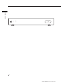
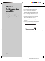
2-514-603-12(1) System Integration 2CH Amplifier Installation Manual Owner’s Record The model and serial numbers are located on the rear panel. Record the model and serial numbers in the spaces provided below. Refer to them whenever you call upon your Sony dealer regarding this product. Model No. Serial No. TA-MR2ES 2004 Sony Corporation 01US01COV-U.p65 1 11/30/04, 12:55 PM SONY TA-MR2ES (US) 2-514-603-12(1) CAUTION WARNING To prevent fire or shock hazard, do not expose the unit to rain or moisture. To avoid electrical shock, do not open the cabinet. Refer servicing to qualified personnel only. You are cautioned that any changes or modification not expressly approved in this manual could void your authority to operate this equipment. If you have any questions about this product, you may call; Sony Customer Information Service Center 1-800-222-7669 or http://www.sony.com/ Welcome! Thank you for purchasing the System Integration 2CH Amplifier. Before operating the unit, please read this manual thoroughly and retain it for future reference. Important Safety Instruction This symbol is intended to alert the user to the presence of uninsulated “dangerous voltage” within the product’s enclosure that may be of sufficient magnitude to constitute a risk of electric shock to persons. This symbol is intended to alert the user to the presence of important operating and maintenance (servicing) instructions in the literature accompanying the appliance. 1 2 3 4 5 6 7 8 9 WARNING This equipment has been tested and found to comply with the limits for a Class B digital device, pursuant to Part 15 of the FCC Rules. These limits are designed to provide reasonable protection against harmful interference in a residential installation. This equipment generates, uses, and can radiate radio frequency energy and, if not installed and used in accordance with the instructions, may cause harmful interference to radio communications. However, there is no guarantee that interference will not occur in a particular installation. If this equipment does cause harmful interference to radio or television reception, which can be determined by turning the equipment off and on, the user is encouraged to try to correct the interference by one or more of the following measures: – Reorient or relocate the receiving antenna. – Increase the separation between the equipment and receiver. – Connect the equipment to an outlet on a circuit different from that to which the receiver is connected. – Consult the dealer or an experienced radio/TV technician for help. 10 11 12 13 14 Read these instructions. Keep these instructions. Heed all warnings. Follow all instructions. Do not use this apparatus near water. Clean only with dry cloth. Do not block any ventilation openings. Install in accordance with the manufacturer’s instructions. Do not install near any heat sources such as radiators, heat registers, stoves, or other apparatus (including amplifiers) that produce heat. Do not defeat the safety purpose of the polarized or grounding-type plug. A polarized plug has two blades with one wider than the other. A grounding type plug has two blades and a third grounding prong. The wide blade or the third prong are provided for your safety. If the provided plug does not fit into your outlet, consult an electrician for replacement of the obsolete outlet. Protect the power cord from being walked on or pinched particularly at plugs, convenience receptacles, and the point where they exit from the apparatus. Only use attachments/accessories specified by the manufacturer. Use only with the cart, stand, tripod, bracket, or table specified by the manufacturer, or sold with the apparatus. When a cart is used, use caution when moving the cart/apparatus combination to avoid injury from tip-over. Unplug this apparatus during lightning storms or when unused for long periods of time. Refer all servicing to qualified service personnel. Servicing is required when the apparatus has been damaged in any way, such as power-supply cord or plug is damaged, liquid has been spilled or objects have fallen into the apparatus, the apparatus has been exposed to rain or moisture, does not operate normally, or has been dropped. 2US 01US02TOC-U.p65 2 11/30/04, 12:56 PM TABLE OF CONTENTS Chapter 1 Getting Started Features 4 Unpacking 5 Parts and Controls 6 Chapter 2 Setting up the amplifier Installing the amplifier 8 Hooking up the Amplifier 10 Selecting the method to activate the amplifier 11 Setting up the IR ID 12 Chapter 3 Operating the amplifier Adjusting the maximum volume level 14 Controlling the amplifier 15 Clearing the amplifier’s memory 15 Chapter 4 Other Information Precautions 16 Troubleshooting 17 Specifications 18 Index 19 3US 01US02TOC-U.p65 3 11/30/04, 12:56 PM Chapter 1 Getting Started This chapter provides you with information on the features and the parts and controls of the amplifier. Features The TA-MR2ES amplifier can be integrated into any multi-room entertainment system. The amplifier allows you to – Create high performance multi-room audio systems with intelligence control features. – Program universal remotes using the unique IR programming function on the rear panel. – Trigger the amplifier using one of three methods. – Cascade amplifiers to power multiple zones using the 12-volt trigger outputs. 4US 01US03CH1-U.p65 4 11/30/04, 1:07 PM Unpacking Getting Started The TA-MR2ES amplifier includes the following: • TA-MR2ES amplifier • AC power cord • Installation Manual (this manual) • Rack-mount brackets (2) • Screw (6) 5US 01US03CH1-U.p65 5 11/30/04, 1:07 PM SONY TA-MR2ES (US) 2-514-603-12(1) Getting Started ON POWER 6US IN USE Rear panel of the amplifier POWER ON / OFF POWER ON POWER OFF 6 MUTING VOL VOL 7 Getting Started 5 8 L IR TEST ON 12V TRIGGER IR IN OFF AUDIO SENSING R 1 2 3 4 TEST IR IN IR OUT IN OUT AUTO POWER SELECTOR IR ID IR REMOTE 12V TRIGGER qs qa q; 9 IN OUT AUDIO 5 IR TEST buttons (page 12) Press the appropriate button to output the IR codes you want to teach through the IR OUT terminal. 6 AUDIO jacks (page 10) a) AUDIO IN RCA jacks for stereo line level audio input from a multi-room system. b) AUDIO OUT RCA jacks for looping out to another amplifier or component. Note This is a buffered audio connection, and this loop-through is active even when the IN USE indicator is off, as long as the AC power cord is plugged in and the POWER switch is on. 7 SPEAKERS (page 10) Terminal which accepts speaker wire sizes up to 12AWG. Leave the AC power cord unplugged when you hook up speaker cables. 8 AC IN (page 10) Removable power cord for easy serviceability of the amplifier. R L SPEAKERS AC IN 9 12V TRIGGER jacks (page 10) a) IN A 3.5 mm monaural mini jack to turn on the amplifier via a 12-volt trigger input. b) OUT Enables the looping of amplifier control from one to the next to trigger multiple amplifiers from a 12-volt trigger output. q; IR REMOTE jacks (page 10) a) IR IN Connects to an outboard IR repeater system so you can operate the amplifier from a distant room. b) IR OUT A 3.5 mm monaural mini jack for the connection of an IR emitter to control other components individually. IR signals received will be routed to the IR sensor of the other components. Outputs IR from the IR TEST system built into the rear of the amplifier. qa IR ID switches (page 12) Select from 12 discrete IR code tables to communicate with up to 12 TA-MR2ES amplifiers (with individual IR ID) on one IR repeater network. qs AUTO POWER SELECTOR switch (page 11) Selects the method for activating the amplifier. 7US 01US03CH1-U.p65 7 11/30/04, 1:07 PM Chapter 2 Setting up the amplifier This chapter provides you with information on the amplifier regarding installation, hookups and settings. Installing the amplifier When you mount the amplifier, note the following: • Place the amplifier on a flat and level surface. • When installing it in a cabinet, make sure the back of the cabinet is open to allow adequate ventilation, prevent heat buildup, and prolong the life of the unit. • Place a board under the amplifier if it is located on a carpet to allow adequate ventilation on the bottom. • Make sure the weight is equally distributed on each of its four feet. • Do not place anything on the top of the amplifier that might block the ventilation holes and cause malfunction. • Do not place anything on the front or rear panel that might damage the amplifier’s control buttons and connectors. • Use caution when placing the unit on surfaces that have been specially treated (with wax, oil, polish, etc.) as staining or discoloration of the surface may result. 7 inches (177.8 mm) minimum 2 inches (50.8 mm) minimum Leave at least 3 inches (76.2 mm) on each side for ventilation. 8US 01US04CH2-U.p65 8 11/30/04, 1:08 PM SONY TA-MR2ES (US) 2-514-603-12(1) If you install the amplifier in a closed cabinet, install two small box fans in the cabinet to provide continuous ventilation. Using rack-mount brackets You can also mount the amplifier into a rack. Make sure that you measure the space needed before mounting. Install the rack-mount brackets onto the amplifier with the supplied screws as shown below. Make sure that the rack-mount brackets are installed securely. 2 Mount the amplifier into the rack as shown below. Make sure that the amplifier is installed securely. Note Attach box fans also if you connect low-impedance speakers (less than 8 ohms nominal). 9US SONY TA-MR2ES (US) 2-514-603-12(1) Setting up the amplifier 1 Hooking up the Amplifier 12V TRIGGER IN jack (B) Hook up the 12V TRIGGER IN jack of the amplifier with an integrated AV system to allow the AV system to activate the amplifier. Use a 3.5 mm monaural mini plug cable. Before hooking up the amplifier, be sure the power cord is unplugged. Refer to the illustration below for the connector locations. Setting up the amplifier IR REMOTE IR IN jack (A) Plug the output from an IR receiver into the IR REMOTE IR IN jack of the amplifier. You can then operate the amplifier by using any IR-based control system. 12V TRIGGER OUT jack (B) Hook up the 12V TRIGGER OUT jack of the amplifier to any 12-volt triggered device. Use a 3.5 mm monaural mini plug cable. Tip Make sure that you match the IR ID switches with the correct code table (page 12). AUDIO IN jack (C) Hook up the audio output of the multi-room system to the AUDIO IN jack of the amplifier. Use RCA audio cables. IR REMOTE IR OUT jack (A) Connect this output to any IR input to pass codes to another device. Use only a 3.5 mm monaural mini plug as shown below. AUDIO OUT jack (C) Hook up the AUDIO OUT jack of the amplifier audio input to any component or to another TA-MR2ES amplifier. Use RCA audio cables. Tip Plug a 3.5 mm monaural mini plug from the IR REMOTE IR OUT jack to the IR REMOTE IR IN jack of the another TA-MR2ES amplifier. Make sure that you match the IR ID switches on the amplifier with the codes set programmed into the controller. SPEAKERS terminals (D) Hook up the speaker cables to the SPEAKERS terminals. Leave the AC power cord unplugged when you hook up speaker cables. Tip: IR AC IN jack (E) Connect the supplied AC power cord to the AC IN jack. Sleeve: Earth Caution Make sure you connect the 3.5 mm monaural mini plug cable to the correct jack on the amplifier. Otherwise, it may cause a malfunction. For example, if you want to connect the mini plug cable to the IR REMOTE IR IN jack, make sure you do not connect it to the 12V TRIGGER IN jack. A POWER ON / OFF POWER ON POWER OFF MUTING VOL B C VOL D E L IR TEST ON 12V TRIGGER IR IN AUDIO SENSING OFF R 1 2 3 4 TEST IR ID AUTO POWER SELECTOR IR IN IR OUT IR REMOTE IN OUT 12V TRIGGER IN OUT AUDIO R L SPEAKERS AC IN 10US 01US04CH2-U.p65 10 11/30/04, 1:08 PM SONY TA-MR2ES (US) 2-514-603-12(1) Selecting the method to activate the amplifier There are three methods to activate the amplifier. Select the turn-on method by setting AUTO POWER SELECTOR as follows: 12V TRIGGER When there is no voltage detected at the trigger input, the amplifier remains off. When the sensing circuitry detects voltage, the amplifier will turn on. When the sensing circuitry detects no voltage, the amplifier turns off instantly. – IR IN When the amplifier detects the appropriate “POWER ON” IR code through the IR REMOTE IR IN, the amplifier will power on. When the amplifier detects the “POWER OFF” IR code, the amplifier turns off instantly. – AUDIO SENSING When there is only a small amount or no audio signal detected at either the left or right input, the amplifier remains off. However, the sensing circuitry is always on. When the sensing circuitry detects sufficient audio signal present at any of the audio inputs, the amplifier will be turned on automatically. The sensing circuitry will wait for around three minutes after the audio signal stops to turn the amplifier off. Setting up the amplifier – Tip Be sure to press POWER to turn on the power after completing all the settings for the amplifier. Otherwise, the amplifier cannot be activated. 11US 01US04CH2-U.p65 11 11/30/04, 1:08 PM SONY TA-MR2ES (US) 2-514-603-12(1) Setting up the IR ID You can set up the IR ID when the IR ID TEST switch is in the “ON” or “OFF” position. 5 Plug the IR emitter to the IR REMOTE IR OUT jack of the amplifier. 6 Make sure the learning remote has been set to learning mode and the IR emitter is touching the learning remote. When the IR ID TEST is “ON” Select this setting to teach the six IR codes below to any IR-based controller. Setting up the amplifier POWER ON / OFF POWER ON POWER OFF IR IN AUDIO SENSING MUTING VOL VOL L IR TEST IR TEST buttons Function ON 12V TRIGGER AUTO POWER SELECTOR POWER ON/OFF To turn on or off the power. POWER ON To turn on the power. OFF R IR IN 1 2 3 4 TEST To turn off the power. MUTING To mute the sound. IN OUT 12V TRIGGER IN OUT AUDIO R L SPEAKERS AC IN IR emitter L POWER OFF IR OUT IR REMOTE IR ID P . > m M Learning remote - X H x F G VOL – To turn down the volume. VOL + To turn up the volume. g f O 1 Make sure that the ATTENUATOR L/R is adjusted to minimum. For details, refer page 14. 2 Turn on the amplifier. 3 Set the IR ID TEST switch to the “ON” position. The IN USE indicator flashes. 7 Press the IR TEST button for the code you want to learn. For example, if you want to learn power on/off, press POWER ON/OFF. The IN USE indicator flashes faster. It takes about 2.5 seconds to complete the learning. During this time, if you press other buttons, they will not function. If learning is not completed, repeat steps 6 and 7. 6 Repeat steps 6 to 7 to learn other buttons. You can then use the remote to operate the amplifier. ON OFF 1 2 3 4 TEST Tips IR ID 4 To output the IR code, for example ID1, set the IR ID 1 switch to the “ON” position and set the rest of the IR ID switches (IR ID 2, 3 and 4) to the “OFF” position. To select other IR ID, refer to the table below. ID1 ID2 ID3 ID4 ID5 ID6 ID7 ID8 ID9 ID10 ID11 ID12 1 2 3 4 ON OFF ON OFF ON OFF ON OFF ON OFF ON OFF OFF ON ON OFF OFF ON ON OFF OFF ON ON OFF OFF OFF OFF ON ON ON ON OFF OFF OFF OFF ON OFF OFF OFF OFF OFF OFF OFF ON ON ON ON ON • Make sure that the IR ID TEST switch is set to the “OFF” position and the IR ID switches is set correctly before using the remote to operate the amplifier. When the IR ID TEST switch is set to “OFF”, the amplifier will turn on at the previous operating condition. • For details on setting the learning remote to learning mode, refer to the operating instructions supplied with the remote. If you set the IR ID other than those listed in the table above, the IR ID will automatically be set to ID1. 12US 01US04CH2-U.p65 12 11/30/04, 1:08 PM SONY TA-MR2ES (US) 2-514-603-12(1) When the IR ID TEST is “OFF” Setting up the amplifier Select this setting before you operate the amplifier. When the IR ID TEST switch is set to the “OFF” position, you can also make the setting below. You can connect up to 12 TA-MR2ES amplifiers (with individual IR ID) in any order. Use an optional IR cable (5 ft.) to make the following connections. Example IR receiver POWER ON / OFF POWER ON POWER OFF IR IN AUDIO SENSING MUTING VOL VOL L IR TEST ON 12V TRIGGER OFF AUTO POWER SELECTOR POWER ON / OFF POWER ON POWER OFF IR IN AUDIO SENSING R 1 2 3 4 TEST VOL IR OUT IR REMOTE IR ID MUTING IR IN IN OUT IN 12V TRIGGER OUT R VOL L SPEAKERS AUDIO AC IN L IR TEST ON 12V TRIGGER AUTO POWER SELECTOR OFF R 1 2 3 4 TEST IR ID IR IN IR OUT IR REMOTE IN OUT 12V TRIGGER IN OUT AUDIO R L SPEAKERS 13US SONY TA-MR2ES (US) 2-514-603-12(1) Chapter 3 Operating the amplifier This chapter provides you with information on amplifier operation. Adjusting the maximum volume level You can control the maximum volume level to avoid damaging your speakers by adjusting the variable attenuator screws behind the cover lid on the front panel. 1 Remove the cover lid. For details, refer page 6. 2 Insert a screw driver into the ATTENUATOR L or ATTENUATOR R screws to adjust the maximum output level of the amplifier to match your system. To increase the volume, turn the screw driver clockwise and to reduce the volume, turn counterclockwise. To adjust to maximum or minimum, turn the screw driver fully. 3 Place the cover lid back to its original position. Tips • You may adjust the left and right output level independantly. • The default setting for the variable attenuator is set to minimum. 14US 01US05CH3-U.p65 14 11/30/04, 1:05 PM Controlling the amplifier You can use the buttons on the remote or control system to control the amplifier. Before using the control system, make sure it has the proper code set (page 12). Adjusting the volume level Press the VOLUME button on the remote to adjust the volume level. There are 70 steps to adjust the volume level from zero to full power. Tip Activating the amplifier This procedure is used to return the settings you have made to their factory defaults. Before clearing the amplifier’s memory, be sure to set the variable attenuator to minimum. 1 Press POWER to turn off the amplifier. 2 Hold down POWER OFF on the rear panel and press POWER on the front panel to turn on the amplifier. The ON indicator flashes 3 times. The following are reset to their factory settings. – Volume level adjusted with learned remote. Operating the amplifier The default setting for the internal IR volume is set to maximum. Make sure you do the steps correctly to avoid damaging the speakers. Clearing the amplifier’s memory – The power status is initialized to “POWER ON” when IR IN is selected in AUTO POWER SELECTOR. Press the POWER button on the remote to activate the amplifier. Tip If you set the AUTO POWER SELECTOR to 12V TRIGGER or AUDIO SENSING, you cannot use the remote to activate the amplifier. Muting the sound Press the MUTING button on the remote to set muting on or off. 15US 01US05CH3-U.p65 15 11/30/04, 1:05 PM Chapter 4 Other Information This chapter provides you with additional information that will help you understand and maintain your system. Precautions On safety • Should any solid object or liquid fall into the cabinet, unplug the amplifier and have it checked by a qualified service technician before operating it any further. • The unit is not disconnected from the AC power source as long as it is connected to the wall outlet, even if the unit itself has been turned off. On power sources • Before operating the unit, check that the operating voltage of the unit is identical to that of your local power supply. The operating voltage is indicated on the nameplate on the back of the unit. • If you are not going to use the unit for a long time, be sure to disconnect it from the AC power source. To disconnect the lead, grasp the plug itself; never pull the cord. On placement • Place the unit in a location with adequate ventilation to prevent heat build-up in the amplifier. • Do not place the unit on a soft surface such as a rug that might block the ventilation holes on the bottom. • Do not place the unit in a location near heat sources, or in a place subject to direct sunlight, excessive dust, or mechanical shock. On adjusting the volume • Do not turn up the maximum volume level by adjusting the ATTENUATOR L/R on the front panel too high while listening to very low input levels. If you do, the speakers may be damaged when high volume source is played. On cleaning • Clean the cabinet, panel, and controls with a soft cloth slightly moistened with a mild detergent solution. Do not use any type of abrasive pad, scouring powder, or solvent, such as alcohol or benzine. If you have any questions or problems concerning the amplifier, please consult your nearest Sony dealer. 16US 01US06CH4-U.p65 16 11/30/04, 1:09 PM Troubleshooting If you experience any of the following difficulties while using the amplifier, use this troubleshooting guide to help you to remedy the problem. Should any problem persist, consult your nearest Sony dealer. Other Information There is no sound, or only a very low-level sound is heard. , Check that the amplifier is turned on. , Check that the speakers are connected correctly and securely. , Press MUTING to check the muting status. , Check to see if the protection circuit on the amplifier has been activated because of a short circuit (the IN USE indicator flashes red). Turn off the amplifier, eliminate the short-circuit problem and turn the power on again. , Adjust the ATTENUATOR on the amplifier and the volume on the learned remote. , If all steps above cannot remedy the problem, clear the amplifier’s memory (page 15). The left and right sounds are unbalanced or reversed. , Check that the speakers and components are connected correctly and securely. , Adjust the ATTENUATOR L and R on the front panel behind the cover lid. There is severe hum or noise. , Check that the speakers are connected securely. , Check that the connecting cords are away from a transformer or motor, and at least 10 feet (3 meters) away from a TV set or fluorescent light. , Move your TV away from the audio components. , The plugs and jacks are dirty. Wipe them with a cloth slightly moistened with alcohol. The IR Remote Control does not function. , Point the Remote Control at the remote sensor on the IR receiver. , Remove any obstacles in the path between the Remote Control and the IR receiver. , Replace both batteries in the Remote Control with new ones, if they are weak. , Check that you have selected the correct function on the Remote Control. , Make sure the IR code setting is correct. , Make sure the IR ID TEST switch is set to “OFF”. The POWER switch is on but the IN USE indicator does not light up when AUTO POWER SELECTOR is set to IR IN. , Clear the amplifier’s memory (page 15). 17US 01US06CH4-U.p65 17 11/30/04, 1:09 PM Specifications Continuous average power output (FTC): 35 W per channel min. RMS at 8 ohms, both channels driven from 20 Hz to 20 kHz with no more than 0.09 % THD. 40 W per channel min. RMS at 4 ohms, both channels driven from 20 Hz to 20 kHz with no more than 0.09 % THD. Frequency responce: 5 Hz – 100 kHz + 0.5/–2 dB Residual noise (A-weighted): 150 µV or less Channel separation (1 kHz/10 kHz): (input 4.7 k ohms terminated) 60 dB/45 dB Signal-to-noise ratio: 94 dB (A-weighted filter, 150 mV input) Audio input Sensitivity: 150 mV Impedance: 50 k ohms Audio output Voltage: minimum 2 V without clipped Other Information Impedance: 1 k ohms S/N: 102 dB (A-weighted filter, 2 V output) General 12V trigger IN: accept 10 ~ 12 V of trigger 12V trigger OUT: 300 mA max IR input: accept up to 40 kHz IR modulation frequency IR output: buffered, 5 V Power requirements: 120 V AC, 60 Hz Power consumption: 100 W Dimensions: 430 ✕ 67 ✕ 350 mm (w/h/d) Mass: 6.5 kg Design and specifications are subject to change without notice. 18US 01US06CH4-U.p65 18 11/30/04, 1:09 PM Index A AC IN L 7, 10 Learning the remote code AC power cord 7, 10 Adjusting volume AUDIO IN jack O, P 14, 15 ATTENUATOR L/R ON indicator 6, 14 6 POWER switch 7, 10 AUDIO OUT jack 12 Precautions 7, 10 AUTO POWER SELECTOR switch 7, 11 6, 15 16 S H, I Selecting the method for activating the amplifer Hookup AC power cord 10 AUDIO IN 10 AUDIO OUT 10 IR REMOTE IR IN 10 IR REMOTE IR OUT 10 SPEAKERS 10 12V TRIGGER IN 10 12V TRIGGER OUT 10 Setting the IR ID Installing the amplifier IR receiver T Troubleshooting 17 Numeral 12V TRIGGER jacks 7, 10 6 Initializing all the settings IR ID switches 7, 10 18 Other Information IN USE indicator 12–13 SPEAKERS terminal Specifications 11 15 8–13 12–13 13 IR Remote Control 12 IR REMOTE IR IN jack 7, 10 IR REMOTE IR OUT jack IR TEST buttons 7, 10 7, 12 19US 01US07CH5-U.p65 19 11/30/04, 1:15 PM 20 Sony Corporation 01US08BCOV-U.p65 Printed in Malaysia 20 11/30/04, 1:14 PM