1
3-742-658-13 (1)
Video Disk
Recorder
Operating Instructions
Before operating the unit, please read this manual
thoroughly and retain it for future reference.
Note
The supplied CD-ROM includes operation manuals
for the DSR-DR1000/DR1000P Video Disk Recorder
(English, Japanese, French, German, Italian and Spanish versions).
For more details, see “Using the CD-ROM Manual” on page 13.
DSR-DR1000/DR1000P
© 2002 Sony Corporation
Owner’s Record
The model and serial numbers are located at the bottom.
Record these numbers in the spaces provided below. Refer
to them whenever you call upon your Sony dealer
regarding this product.
Model No.
Serial No.
WARNING
To prevent fire or shock hazard, do not
expose the unit to rain or moisture.
To avoid electrical shock, do not open the
cabinet. Refer servicing to qualified
personnel only.
This symbol is intended to alert the user to
the presence of uninsulated “dangerous
voltage” within the product’s enclosure
that may be of sufficient magnitude to
constitute a risk of electric shock to
persons.
This symbol is intended to alert the user to
the presence of important operating and
maintenance (servicing) instructions in
the literature accompanying the
appliance.
WARNING: THIS WARNING IS APPLICABLE FOR
USA ONLY.
Using this unit at a voltage other than 120 V may require
the use of a different line cord or attachment plug, or both.
To reduce the risk of fire or electric shock, refer servicing
to qualified service personnel.
THIS APPARATUS MUST BE EARTHED.
Do not install the appliance in a confined space, such as a
book case or built-in cabinet.
For customers in the USA (DSR-DR1000 only)
This equipment has been tested and found to comply with
the limits for a Class A digital device, pursuant to Part 15
of the FCC Rules. These limits are designed to provide
reasonable protection against harmful interference when
the equipment is operated in a commercial environment.
This equipment generates, uses, and can radiate radio
frequency energy and, if not installed and used in
accordance with the instruction manual, may cause
harmful interference to radio communications. Operation
of this equipment in a residential area is likely to cause
harmful interference in which case the user will be
required to correct the interference at his own expense.
This apparatus is provided with a main switch on the rear
panel. Install this apparatus so that user can access the
main switch easily.
You are cautioned that any changes or modifications not
expressly approved in this manual could void your
authority to operate this equipment.
CAUTION
The apparatus shall not be exposed to dripping or
splashing and no objects filled with liquid, such as vases,
shall be placed on the apparatus.
The unit is not disconnected from the AC power source
(mains) as long as it is connected to the wall outlet, even if
the unit itself has been turned off.
The shielded interface cable recommended in this manual
must be used with this equipment in order to comply with
the limits for a digital device pursuant to Subpart B of Part
15 of FCC Rules.
2
Important Safety Instructions
•
•
•
•
•
•
•
•
•
•
•
•
Read these instructions.
Keep these instructions.
Heed all warnings.
Follow all instructions.
Do not use this apparatus near water.
Clean only with dry cloth.
Do not block any ventilation openings.
Install in accordance with the manufacturer’s
instructions.
Do not install near any heat sources such as radiators,
heat registers, stoves, or other apparatus (including
amplifiers) that produce heat.
Do not defeat the safety purpose of the polarized or
grounding-type plug. A polarized plug has two blades
with one wider than the other. A grounding-type plug
has two blades and a third grounding prong. The wide
blade or the third prong are provided for your safety. If
the provided plug dose not fit into your outlet, consult an
electrician for replacement of the obsolete outlet.
Protect the power cord from being walked on or pinched
particularly at plugs, convenience receptacles, and the
point where they exit from the apparatus.
Only use attachments/accessories specified by the
manufacturer.
Use only with the cart, stand, tripod, bracket, or table
specified by the manufacturer, or sold with the
apparatus.
When a cart is used, use caution when moving the cart/
apparatus combination to avoid injury from tip-over.
• Unplug this apparatus during lightning storms or when
unused for long periods of time.
• Refer all servicing to qualified service personnel.
Servicing is required when the apparatus has been
damaged in any way, such as power-supply cord or plug
is damaged, liquid has been spilled or objects have fallen
into the apparatus, the apparatus has been exposed to
rain or moisture, does not operate normally, or has been
dropped.
Caution
Television programs, films, video tapes and other
materials may be copyrighted.
Unauthorized recording of such material may be contrary
to the provisions of the copyright laws.
For customers in Europe (DSR-DR1000P only)
This product with the CE marking complies with both the
EMC Directive (89/336/EEC) and the Low Voltage
Directive (73/23/EEC) issued by the Commission of the
European Community.
Compliance with these directives implies conformity to
the following European standards:
• EN60065: Product Safety
• EN55103-1: Electromagnetic Interference (Emission)
• EN55103-2: Electromagnetic Susceptibility (Immunity)
This product is intended for use in the following
Electromagnetic Environment(s):
E1 (residential), E2 (commercial and light industrial), E3
(urban outdoors) and E4 (controlled EMC environment,
ex. TV studio).
Voor de Klanten in Nederland
• Dit apparaat bevat een vast ingebouwde batterij die niet
vervangen hoeft te worden tijdens de levensduur van het
apparaat.
• Raadpleeg uw leverancier indien de batterij toch
vervangen moet worden.
De batterij mag alleen vervangen worden door
vakbekwaam servicepersoneel.
• Gooi de batterij niet weg maar lever deze in als klein
chemisch afval (KCA).
• Lever het apparaat aan het einde van de levensduur in
voor recycling, de batterij zal dan op correcte wijze
verwerkt worden.
3
AVERTISSEMENT
Afin d’éviter tout risque d’incendie ou
d’électrocution, ne pas exposer l’appareil
à la pluie ou à l’humidité.
Afin d’écarter tout risque d’électrocution,
garder le coffret fermé. Ne confier
l’entretien de l’appareil qu’à un personnel
qualifié.
CET APPAREIL DOIT ÊTRE RELIÉ À LA
TERRE.
ATTENTION
Eviter d’exposer l’appareil à un égouttement ou à des
éclaboussures et ne placer aucun objet rempli de liquide,
comme un vase, sur l’appareil.
Cet appareil n’est pas déconnecté de la source
d’alimentation secteur tant qu’il est raccordé à la prise
murale, même si l’appareil lui-même a été mis hors
tension.
Des programmes de télévision, films, bandes vidéo et
autres peuvent être protégés par des droits d’auteur.
L’enregistrement non autorisé de tels matériaux risque de
constituer une violation de ces droits d’auteur.
Ne pas installer l’appareil dans un endroit confiné, par
exemple une bibliothèque ou un placard encastré.
Cet appareil possède son interrupteur principal sur le
panneau arrière.
Installer l’appareil de façon que l'utilisateur puisse accéder
facilement à l'interrupteur principal.
AVERTISSEMENT : CET AVERTISSEMENT NE
S’APPLIQUE QU’AUX ETATS-UNIS.
L’alimentation de l’appareil sur une tension autre que 120
V peut nécessiter l’utilisation d’un cordon de ligne ou
d'une fiche différents, ou des deux. Pour réduire tout risque
de feu ou de choc électrique, confier toute réparation à un
personnel qualifié.
Pour les clients européens
(DSR-DR1000P seulement)
Ce produit portant la marque CE est conforme à la fois à la
Directive sur la compatibilité électromagnétique (EMC)
(89/336/CEE) et à la Directive sur les basses tensions
(73/23/CEE) émises par la Commission de la
Communauté européenne.
4
La conformité à ces directives implique la conformité aux
normes européennes suivantes:
• EN60065: Sécurité des produits
• EN55103-1: Interférences électromagnétiques
(émission)
• EN55103-2: Sensibilité électromagnétique (immunité)
Ce produit est prévu pour être utilisé dans les
environnements électromagnétiques suivants:
E1 (résidentiel), E2 (commercial et industrie légère),
E3 (urbain extérieur) et E4 (environnement EMC contrôlé
ex. studio de télévision).
VORSICHT
Um Feuergefahr und die Gefahr eines elektrischen
Schlages zu vermeiden, darf das Gerät weder Regen noch
Feuchtigkeit ausgesetzt werden.
Um einen elektrischen Schlag zu vermeiden, darf das
Gehäuse nicht geöffnet werden. Überlassen Sie
Wartungsarbeiten stets nur qualifiziertem Fachpersonal.
1. Für Ihren privat genutzten Videorecorder muß eine
Fernseh-Rundfunk-Genehmigung beantragt
werden, sofern nicht bereits eine Genehmigung für
ein Fernsehgerät desselben Haushaltes vorliegt. Im
geschäftlichen Bereich ist jeder einzelne
Videorecorder anmelde- und gebührenpflichtig.
(Auskunft ggf. bei der GEZ oder den
Rundfunkanstalten.)
DIESES GERÄT MUSS GEERDET WERDEN.
ACHTUNG
Das Gerät ist nicht tropf- und spritzwassersicher, daher
dürfen keine mit Flüssigkeiten gefüllten Gegenstände,
z. B. Vasen, darauf abgestellt werden.
Solange das Netzkabel an eine Netzsteckdose
angeschlossen ist, bleibt das Gerät auch im
ausgeschalteten Zustand mit dem Stromnetz verbunden.
Das Gerät nicht an Orten aufstellen, z.B. in Bücherregalen
oder Einbauschränken, wo keine ausreichende Belüftung
gewährleistet ist.
Der Hauptschalter dieses Geräts befindet sich an der
Rückwand.
Stellen Sie das Gerät so auf, dass jederzeitiger Zugriff auf
diesen Hauptschalter gewährleistet ist.
2. Im privaten Bereich ist die Aufzeichnung von
urheberrechtlich geschützten Werken auf Bildund Tonträger gestattet. Die entsprechenden
Urheber- Vergütungen sind im Kaufpreis des
Gerätes enthalten. Öffentliche Wiedergabe oder
Verbreitung von mitgeschnittenen
Fernsehsendungen ist ohne Erlaubnis nicht
zulässig, verpflichtet zu Schadenersatz und ist
gegebenenfalls strafbar.
3. Im Rahmen der Regelung des §47 des
Urheberrechtsgesetzes sind Aufzeichnungen von
Schulfernsehprogrammen gestattet. Mitschnitte
von Schulfunksendungen dürfen jedoch nur für
den Unterricht verwendet werden und sind
spätestens am Ende des laufenden Schuljahres zu
löschen.
Zum Netzanschluß dieses Gerätes ist eine geprüfte Leitung
zu verwenden. Es sind die zutreffenden nationalen
Errichtungs- und/oder Gerätebestimmungen zu beachten.
(Für einen Nennstrom bis 6A)
Es ist eine geprüfte flexible PVC-ummantelte Leitung
entsprechend IEC 60227 (H05VV-F 3G 0.75 mm2 oder
H05VVH2-F 3G 0.75 mm2) zu verwenden.
Andernfalls ist eine flexible Leitung aus systhetischem
Gummi entsprechend IEC60245 (Bauartkurzzeichen
H05RR-F 3G 0.75 mm2) zu verwenden.
Für Kunden in Europa (DSR-DR1000P)
Dieses Produkt besitzt die CE-Kennzeichnung und erfüllt
sowohl die EMV-Direktive (89/336/EEC) als auch die
Direktive Niederspannung (73/23/EEC) der
EG-Kommission.
Die Erfüllung dieser Direktiven bedeutet Konformität für
die folgenden Europäischen Normen:
• EN60065: Produktsicherheit
• EN55103-1: Elektromagnetische Interferenz (Emission)
• EN55103-2: Elektromagnetische Empfindlichkeit
(Immunität)
Dieses Produkt ist für den Einsatz unter folgenden
elektromagnetischen Bedingungen ausgelegt:
E1 (Wohnbereich), E2 (kommerzieller und in
beschränktem Maße industrieller Bereich), E3
(Stadtbereich im Freien) und E4 (kontrollierter EMVBereich, z.B. Fernsehstudio).
5
ATTENZIONE
Per evitare il pericolo di incendi o scosse elettriche, non
esporre l’apparecchio alla pioggia o all’umidità.
Per evitare scosse elettriche, non aprire l’apparecchio.
Per le riparazioni, rivolgersi solo a personale qualificato.
QUESTO APPARECCHIO DEVE ESSERE MESSO A
TERRA.
Grabadora de disco duro
ADVERTENCIA
Para evitar el riesgo de incendios o electrocución, no
exponga la unidad a la lluvia ni a la humedad.
Para evitar descargas eléctricas, no abra el aparato.
Solicite asistencia técnica únicamente a personal
especializado.
ESTE APARATO DEBE CONECTARSE A TIERRA.
ATTENZIONE
L’apparecchio non deve essere esposto a gocciolamenti o
spruzzi. Non collocare sull’apparecchio oggetti contenenti
liquidi, come ad esempio vasi di fiori.
L’apparecchio non è scollegato dalla fonte di
alimentazione CA (corrente di rete) fintanto che è
collegato ad una presa di corrente, anche se l’apparecchio
stesso è stato spento.
Programmi televisivi, film, videonastri e altro materiale
possono essere tutelati dai diritti d’autore.
Registrazioni non autorizzate di tali materiali possono
infrangere la legge sui diritti d’autore.
Evitate di installare l’apparecchio in uno spazio limitato,
tipo in una libreria o in un mobiletto incassato.
Questo apparecchio è provvisto di interruttore principale
posizionato sul pannello posteriore.
Installare l’apparecchio in modo tale che l’utente possa
accedere facilmente all’interruttore principale.
Per i clienti in Europa
(DSR-DR1000P soltanto)
Questo prodotto recante il marchio CE è conforme sia alla
direttiva sulla compatibilità elettromagnetica (EMC) (89/
336/CEE) che alla direttiva sulle basse tensioni (73/23/
CEE) emesse dalla Commissione della Comunità Europea.
La conformità a queste direttive implica la conformità alle
seguenti normative europee:
• EN60065: Sicurezza dei prodotti
• EN55103-1: Interferenza elettromagnetica (Emissione)
• EN55103-2: Sensibilità ai disturbi elettromagnetici
(Immunità)
Questo prodotto è destinato all’uso nei seguenti ambienti
elettromagnetici:
E1 (residenziali), E2 (commerciali e industriali leggeri),
E3 (esterni urbani) e E4 (ambienti EMC controllati, ad
esempio studi televisivi).
6
PRECAUCIÓN
No se debe exponer la unidad a derrames ni goteos, ni se
debe situar cerca objetos llenos de líquido, como por
ejemplo vasos.
La unidad no queda desconectada de la alimentación
eléctrica siempre que esté conectado al tomacorriente
incluso aunque se desconecte el interruptor principal.
Los programas de televisión, las películas, las cintas de
vídeo y material similar pueden estar protegidos por las
leyes de copyright.
La grabación no autorizada de dicho material puede ir en
contra de lo establecido por las leyes de copyright.
No instale el aparato en un lugar estrecho como en una
biblioteca o mueble integrado.
Este aparato tiene el interruptor principal en el panel
trasero.
Instale este aparato de tal forma que pueda utilizar
fácilmente el interruptor principal.
Para los clientes de Europa (DSR-DR1000P sólo)
Este producto cumple con las directivas de compatibilidad
electromagnética (89/336/CEE) y baja tensión (73/23/
CEE) de la Comisión Europea.
El cumplimiento de estas directivas implica la
conformidad con los siguientes estándares europeos:
• EN60065: Seguridad del producto
• EN55103-1: Interferencia electromagnética (Emisión)
• EN55103-2: Susceptibilidad electromagnética
(Inmunidad)
Este producto está ha sido diseñado para utilizarse en los
entornos electromagnéticos siguientes:
E1 (zona residencial), E2 (zona comercial e industrial
ligera),
E3 (exteriores urbanos), y E4 (entorno con EMC
controlada, p. ej., estudio de televisión).
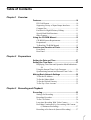
Table of Contents
Chapter 1 Overview
Features......................................................................10
DVCAM Format ........................................................... 10
Supporting Variety of Input/Output Interfaces ............. 10
Compact Size ................................................................ 11
Facilities for High-Efficiency Editing........................... 11
Special Hard Disk Functions......................................... 11
Other Features ............................................................... 12
Using the CD-ROM Manual .......................................13
CD-ROM System Requirements................................... 13
Preparations................................................................... 13
To Read the CD-ROM Manual ..................................... 13
Location and Function of Parts................................14
Front Panel .................................................................... 14
Rear Panel ..................................................................... 23
Chapter 2 Preparations
Setting the Date and Time ........................................27
Setting the Time Data................................................27
Displaying Time Data and Operation Mode Indications ..
28
Using the Internal Time Code Generator...................... 29
Synchronizing Internal and External Time Codes ........ 31
Making Basic Network Settings ...............................32
To Set the IP Address.................................................... 32
To Set the Subnet Mask ................................................ 32
To Set the Default Gateway .......................................... 32
To Set Up a User Account ............................................ 32
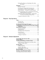
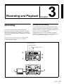
Chapter 3 Recording and Playback
Recording...................................................................33
Settings for Recording .................................................. 33
Recording Procedure..................................................... 35
To Set Cue Points.......................................................... 36
Long-time Recording With Video Camera ................... 36
Recording Continuously by Overwriting Old Content
(Continuous Recording) ...................................... 37
Recording at Set Intervals (Interval Recording) ........... 37
7
Starting Recording at an Alarm Input (Pre-Alarm
Recording) ........................................................... 37
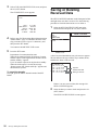
Playback .....................................................................37
Playback Procedure....................................................... 37
Recording and Playing Back Simultaneously............... 38
Setting Points A and B for Repeat Playback................. 39
Repeat Playback —Automatic Cyclical Playback ........ 42
Connecting Multiple Units for Simultaneous Playback
(Multi-Simultaneous Playback)........................... 42
High-Speed and Low-Speed Search —Quickly and
Accurately Determining Editing Points............... 43
Cueing Up a Desired Cue Point .................................... 44
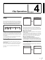
Chapter 4 Clip Operations
Clips............................................................................45
Deleting Clips ............................................................... 45
Protecting Clips............................................................. 45
To Search in Clip Units (Clip Jump) ........................46
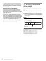
Playing Back Scenes Extracted From Clips (Program
Playback) .............................................................47
Working with Playlists ..............................................48
Displaying Playlists....................................................... 48
Editing Playlists ............................................................ 48
Saving the Current Playlist Data................................... 49
Saving Playlists ............................................................. 49
To Delete a Playlist ....................................................... 50
Exiting the Clip Menu................................................... 50
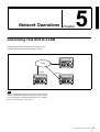
Chapter 5 Network Operations
Connecting This Unit to a LAN.................................51
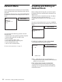
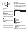
Network Menu ............................................................52
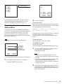
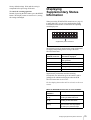
Creating and Editing an Address Book ...................52
Registering Host information in an Address Book ....... 53
Editing an Address Book .............................................. 54
Sending Data..............................................................55
Sending Clip Data ......................................................... 55
Sending Cliplist Data .................................................... 56
Sending Address Book Data ......................................... 56
Receiving Data...........................................................57
Saving or Deleting Received Data ...........................58
Checking Communications Status ..........................59
8
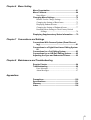
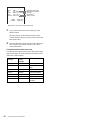
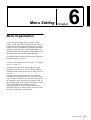
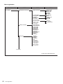
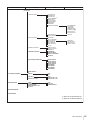
Chapter 6 Menu Setting
Menu Organization ....................................................61
Menu Contents...........................................................64
Setup Menu ................................................................... 64
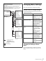
Changing Menu Settings ..........................................75
Buttons Used to Change Settings.................................. 75
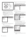
Changing the Settings of Basic Items ........................... 75
Displaying Enhanced Items .......................................... 77
Changing the Settings of Enhanced Items .................... 77
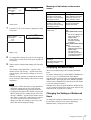
Returning Menu Settings to Their Factory Default
Settings ................................................................ 78
Displaying Supplementary Status Information.......79
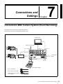
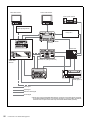
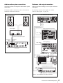
Chapter 7 Connections and Settings
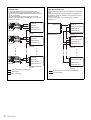
Connections With Camera System (Event Recording) .......................................................................81
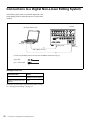
Connections to a Digital Non-Linear Editing System
82
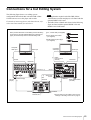
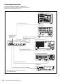
Connections for a Cut Editing System ....................83
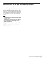
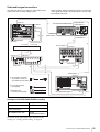
Connections for an A/B Roll Editing System ..........85
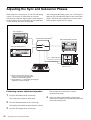
Adjusting the Sync and Subcarrier Phases ............92
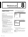
Chapter 8 Maintenance and Troubleshooting
Regular Checks .........................................................94
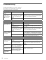
Troubleshooting ........................................................96
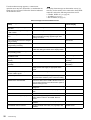
Error Messages.............................................................. 97
Alarm Messages ............................................................ 97
Appendixes
Precautions ..............................................................100
Specifications ..........................................................101
Glossary ...................................................................104
Index .........................................................................106
9
Overview
Features
Chapter
1
to one-fifth size before being recorded to ensure stable and
superb picture quality.
High-quality PCM digital audio
The DSR-DR1000/DR1000P is a digital videodisk
recorder using the DVCAMTM digital recording format. It
is the first professional DVCAM studio recorder to feature
a hard disk as its recording media.
The DSR-DR1000/DR1000P supports the jog, shuttle, and
variable playback modes found on conventional VTRs,
together with jog sound. In addition, it supports many
convenient functions possible only on a hard disk recorder,
such as simultaneous recording and playback, random
access, and interval recording.
This unit is equipped with an i.LINK* interface supporting
the AV/C and SBP2 protocols, which allows it to transfer
data at high speeds. It is also equipped with an Ethernet
connector, allowing it to be connected to a LAN for
transferring recorded data as files.
This unit can be used as a recorder in combination with
video cameras and players, and incorporated in a
conventional editing system as a professional feeder.
Because it adds a variety of convenient hard disk functions
to the functionality of a conventional VTR, it can
significantly increase editing efficiency.
Supporting Variety of Input/Output
Interfaces
Digital interfaces
The following are the principal features of the unit.
The following optional digital interfaces can be used with
the unit.
SDI (serial digital interface)/AES/EBU: It can input and
output D1 (component) format digital video and audio
signals and also AES/EBU-format digital audio
signals.
i.LINK: DV format digital video and audio signals can be
input and output. This unit supports the SBP2
protocol. Connecting an SBP2 compliant PC allows
video and audio data to be transferred at high speeds.
DVCAM Format
Analog interfaces
* i.LINK and are trademarks and indicate that this product is in agreement
with IEEE1394-1995 specifications and their revisions.
DVCAM is a professional digital recording format
developed by Sony from the consumer DV component
digital format.
High picture quality and high stability
Video signals are separated into color difference signals
and luminance signals, which are encoded and compressed
10
PCM recording makes for a wide dynamic range and a
high signal-to-noise ratio, thereby enhancing sound
quality.
There are two recording modes: 2-channel mode (48-kHz
sampling and 16-bit quantization), which offers sound
quality equivalent to the DAT (Digital Audio Tape)
format, or 4-channel mode (32-kHz sampling and 12-bit
quantization).
Features
The unit can also use the following analog interfaces.
• Analog video: These interfaces include a component
interface, composite interface, and S-video interface.
The same BNC type input and output connectors are
used to input and output signals in different formats
selected with front panel buttons for input and menu
items for output.
• Analog audio: The unit has two audio channels. When
in 4-channel mode, you can input two channels of audio
either as channels 1 and 2 or as channels 3 and 4. The two
audio channels can be output also either as channels 1
and 2 or as channels 3 and 4.
DMC (Dynamic Motion Control)
Under the control of external control devices, this unit can
play back editing segments over the range –2 to +2 times
normal speed.
Compact Size
The compact size of the unit makes the unit suitable for use
on a desk top or in an outside broadcast van. The unit can
be used as feeder machine for non-linear editing.
Facilities for High-Efficiency Editing
200% variable playback
This unit is the first DVCAM format player or recorder to
provide noiseless, variable speed playback over the range
from –2 to +2 times normal speed.
Superimposition function
Time code values, operation mode indications, error
messages, and other text data can be superimposed on
analog composite video signals output from the SUPER
connector. The SUPER connector is a special connector
for output of text information. It can be used independently
when you are outputting composite video, component
video, S-Video and other video signals.
Special Hard Disk Functions
Extended recording times
Digital jog sound function
When searching at speeds in the range ±2 times normal
speed, the digital jog sound function is enabled. The audio
signal is saved in temporary memory, and replayed
according to the search speed. This allows searching on the
sound track.
Video process control
For analog video output and SDI-format video output,
you can adjust the video output level, chroma signal
output level, setup level (for DSR-DR1000), black level
(for DSR-DR1000P), and chroma phase using the setup
menu.
Search dial
This unit is equipped with a responsive search dial for jog
and shuttle playback.
Internal and external time codes
An internal time code generator and reader enables time
code compliant with SMPTE (for DSR-DR1000)/EBU
(DSR-DR1000P) format to be recorded and played back.
This allows editing to single frame precision.
Outputting or inputting time code (LTC) to or from an
external device is also possible using the TIME CODE IN/
OUT connectors.
The unit is also compatible with VITC.
Remote control
This unit has two RS-422A connectors for
communications with external editors with RS-422A
interfaces. Remote control is also possible via the supplied
RM-LG2 remote control unit and over the i.LINK
interface.
The unit is equipped with a mass storage hard disk, which
allows a maximum of 6 hours of 25 Mbps DVCAM stream
signals to be recorded.
Rich variety of recording modes
• Normal recording: Input signals are recorded to the
hard disk. A single clip* is created by recording start and
stop operations.
• Continuous (endless) recording: This mode allows
continuous recording of new material to the hard disk,
overwriting old material when the disk becomes full.
This mode is suitable for meteorological and biological
observations, which require long continuous recording
times.
• Interval recording: This mode allows recording at
specified intervals. You can set the length of the
recording interval and the length of the standby time
until the next recording interval. The recording interval
can be set to 0.5, 1, 1.5, or 2 seconds, and the standby
interval to 30 seconds or 1, 5, or 10 minutes. This is
effective in situations such as biological observations
when long interval recording times are required.
• Pre-alarm (exterenal trigger) recording: In this mode,
recording is triggered by an alarm signal input from an
external device. For example, when an alarm signal is
received, the unit begins recording. Moreover the
recording includes data for the 30 seconds prior to
reception of the alarm signal (this data is continuously
saved in advance on the hard disk).
* Material recorded by this unit is handled in units called “clips”, which
contain the data from the start point to the end point of one recording
operation. Note that there is a limit of 500 on the number of clips that
can be saved, regardless of the available hard disk space.
Features
11
Simultaneous recording and playback
While recording input signals to the hard disk, this unit is
capable of simultaneous normal speed or slow-motion*
playback of any materials already recorded on the hard
disk.** During recording, cue points can be set at any point
from the control panel or from the supplied RM-LG2
Remote Control Unit, and the unit can go back to play the
material from the cue points. This makes it possible for this
unit alone to provide slow-motion playback of highlight
scenes and other kinds of replay required in broadcasts of
sporting and live events.
* Slow-motion playback during recording is possible over the range (normal
speed.
**Playback of the clip currently being recorded is not possible during
continuous recording.
Program playback (clip segment playback)
You can extract scenes (up to 100 scenes) anywhere in the
materials on the hard disk to create playlists. This unit
follows the playlist to play the materials automatically,
allowing you to play sequences with this unit alone. You
can check and modify the lists on the monitor.
Multi-simultaneous playback (9-pin (PARA)
function)
Via the two RS-422A connectors, multiple DSR-DR1000/
DR1000P units can be connected in a cascade connection,
for simultaneous playback without delay. This is
convenient in situations such as output to multiple
monitors. To perform multi-simultaneous playback, you
need to set the REMOTE I/F menu item (see page 72) to
9PIN(PARA).
Other Features
Support for two i.LINK protocols
This unit supports the AV/C protocol, used for input and
output of digital video and audio signals in the DV format,
and the SBP2 protocol, used for high-speed transfer of
video and audio data. By connecting SBP2 compatible
nonlinear devices or servers, you can transfer data at fast
speed.
Ethernet modular jack
You can connect this unit to a LAN to transfer material. In
addition to transferring clips, you can also extract and
transfer individual scenes.
12
Features
Menu system for functionality and
operation settings
The unit provides a menu system to make its various
functions easier to use and set up its operation conditions.
Self-diagnostic/alarm function
This function automatically detects setup and connection
errors, operation faults, and other problems. It also
displays a description of the problem, its cause, and the
recommended response on the video monitor screen or
time counter display.
Internal test signal generator
The unit has built-in video and audio test signal generators.
The video test signal generator can produce either a color
bar signal or a black burst signal. The audio test signal
generator can generate either a silent signal or a 1-kHz sine
wave signal. Menu items are provided for selecting the test
signals to be generated.
Reference signal connection
The reference video input connector of the unit is provided
with a loop-through connector which can be used to
connect the input reference video signal to other
equipment. When there is no loop-through connection, the
reference video input connector is automatically provided
with a 75-ohm termination.
Compatible with wide-screen aspect ratio
(16:9)
The unit can record and play back aspect ratio information.
When video accompanied by wide-screen aspect ratio
information is recorded or played back, the unit can output
the video signal also containing the aspect ratio
information.
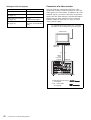
Using the CD-ROM Manual
The supplied CD-ROM includes operation manuals for the
DSR-DR1000/DR1000P Video Disk Recorder (English,
Japanese, French, German, Italian and Spanish versions).
CD-ROM System Requirements
The following are required to access the supplied CDROM
disc.
• Computer: PC with MMX Pentium 166 MHz or faster
CPU, or Macintosh computer with PowerPC CPU.
- Installed memory: 32 MB or more
- CD-ROM drive: 8 or faster
• Monitor: Monitor supporting resolution of 800 × 600 or
higher
When these requirements are not met, access to the CDROM disc may be slow, or not possible at all.
A PDF file of the operation manual opens.
Note
If you lose the CD-ROM disc or become unable to read its
content, for example because of a hardware failure, contact
a Sony service representative.
• MMX and Pentium are registered trademarks of Intel Corporation or its
subsidiaries in the United States and other countries.
• PowerPC is a registered trademark of International Business Machines
Corporation.
• Macintosh is a registered trademark of Apple Computer, Inc.
• Microsoft is a registered trademark of Microsoft Corporation in the United
States and/or other countries.
• Netscape Navigator is a registered trademark of Netscape
Communications Corporation in the U.S. and other countries.
• Adobe and Acrobat are registered trademarks of Adobe Systems
Incorporated in the United States and/or other countries.
Preparations
The following software must be installed on your
computer in order to use the operation manuals contained
in the CD-ROM disc.
• Microsoft Internet Explorer Version 4.0 or higher, or
Netscape Navigator Version 4.0 or higher
• Adobe Acrobat Reader Version 4.0 or higher
Notes
• If Microsoft Internet Explorer is not installed, it may be
downloaded from the following URL:
http://www.microsoft.com/ie
• If Netscape Navigator is not installed, it may be
downloaded from the following URL:
http://home.netscape.com/
• If Adobe Acrobat Reader is not installed, it may be
downloaded from the following URL:
http://www.adobe.com/products/acrobat/readstep.html
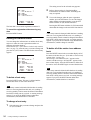
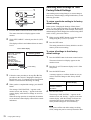
To Read the CD-ROM Manual
To read the operation manual contained in the CDROM
disc, do the following.
1
Insert the CD-ROM disc in your CD-ROM drive.
A cover page appears automatically in your browser.
If it does not appear automatically in the browser,
double click the index.htm file on the CD-ROM disc.
2
Select and click the operation manual that you want to
read.
Using the CD-ROM Manual
13
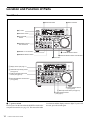
Location and Function of Parts
Front Panel
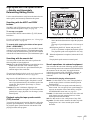
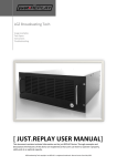
0 Status indicators
qa Audio level meters
a 1 switch
2 SC/SYNC control
3 Control mode
selector
4 PHONES connector
and control knob
5 METER CH-1/2 3/4 button
6 MONITOR SELECT button
9 COUNTER SELECT button
8 LINE OUT SELECT button and indicators
7 CLIP button
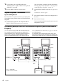
1 Display section (see page 17)
2 Video/audio input setting section
(see page 19)
3 Audio input/output level control
section (see page 20)
4 Recording/playback control section
(see page 20)
7 Search operation section
(see page 22)
6 Menu/clip control section (see page 21)
5 PANEL SELECT section
(see page 21)
a 1 (power) switch
Press to power on the unit when the POWER switch on the
rear panel is turned on (see page 23). This causes the audio
14
Location and Function of Parts
level meters and the display section to light. To power off
the unit, press the switch again.
b SC (subcarrier phase)/SYNC (synchronization
phase) control
Turn the SC control to accurately adjust the subcarrier
phase of the composite video output signal of the unit with
respect to the reference video signal.
c Control mode selector
Selects whether the unit is operated from its front panel or
from external equipment.
KEY INHI (key inhibit): All controls in the recording/
playback control section and the search control section
are disabled. In this state, the unit cannot be operated
from its front panel or from a remote control unit
connected to the CONTROL connector.
LOCAL: The unit is operated from its front panel or from
an RM-LG2 Remote Control Unit (supplied)
connected to the CONTROL connector.
REMOTE: The unit is operated from external equipment
connected to the REMOTE IN (R)/OUT (P)connectors
or S400(i.LINK) connector on the rear panel.
Select which of the connectors to use with the
REMOTE I/F menu item (see page 72).
d PHONES connector (stereo phone jack) and
control knob
Connect stereo headphones to the connector for audio
monitoring during recording or playback. The control
knob controls the volume of the headphones. It also
controls the level of the audio signal output from the
MONITOR connector on the rear panel.
The settings made with the METER CH-1/2 3/4 button and
MONITOR SELECT button select the audio channels for
audio output via this connector. The same channel
selection as for the audio level meters applies to this
connector.
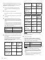
e METER CH-1/2 3/4 button
Pressing this button toggles the audio level meter mode
between CH-1/2 (channels 1 and 2) and CH-3/4 (channels
3 and 4).
The settings made with this button and the MONITOR
SELECT button select the channels for level indications
and audio output.
For more details, see “6 MONITOR SELECT button.”
f MONITOR SELECT button
Use this button and the METER CH-1/2 3/4 button to
select the audio channels:
• for level indications on the audio level meters
• for audio output via the PHONES connector on the front
panel
• for audio output via the MONITOR connector on the
rear panel
Depending on the setting made with the METER CH-1/2
3/4 button, the channels for output to the above meters and
connectors are selected as follows.
When CH-1/2 mode is selected with the METER CH-1/
2 3/4 button:
Audio level meters
PHONES
connector
CH-1 (channel 1) only.
Only the left meter lights.
Channel 1 only Channel 1 only
(monaural)
CH-2 (channel 2) only.
Only the right meter
lights.
Channel 2 only Channel 2 only
(monaural)
CH-1 and CH-2 (channels Channels 1
1 and 2).
and 2 (stereo)
Both the left and right
meters light.
MONITOR
connector
Channels 1
and 2 (mixed)
When CH-3/4 mode is selected with the METER CH-1/
2 3/4 button:
Audio level meters
PHONES
connector
CH-3 (channel 3) only.
Only the left meter lights.
Channel 3 only Channel 3 only
(monaural)
CH-4 (channel 4) only.
Only the right meter
lights.
Channel 4 only Channel 4 only
(monaural)
CH-3 and CH-4 (channels Channels 3
3 and 4).
and 4 (stereo)
Both the left and right
meters light.
MONITOR
connector
Channels 3
and 4 (mixed)
g CLIP button
This button is used for setting up and modifying clip lists,
and for clip segment playback operations.
See Chapter 4 for details about clip operations.
h LINE OUT SELECT button and indicators
When you are recording and playing back at the same time,
use this button to select output of playback or recording
signals. Each press of the button selects the other signals.
Recording signals are output when the R indicator is lit.
Playback signals are output when the P indicator is lit.
When the R indicator is lit: Recording signals are output.
When the P indicator is lit: Playback signals are output.
When both indicators are lit: Output signals are
recording signals or playback signals, as selected by
the R button and the P button in the PANEL SELECT
section (see page 21). Output signals can also be
switched from an external device connected to the
REMOTE OUT(P) connector.
See “To select output signals during simultaneous
recording and playback” on page 38 for more information
about selecting the output during simultaneous recording
and playback.
Location and Function of Parts
15
i COUNTER SELECT button
Selects the type of time data to be shown in the time
counter display. Each press of this button cycles through
the following three indicator display options:
• COUNTER (CNT: count value of the time counter)
• TC (time code)
• U-BIT (user bits)
Note
If the Control mode selector is set to REMOTE, the
COUNTER SELECT button does not operate. In this case,
make the time data selection via the external equipment
connected to the REMOTE IN (R)/OUT (P) connectors on
the rear panel.
j Status indicators
This indicate the current status of the unit.
CONTINUOUS REC: When this indicator is lit, the unit
will return to the first recording start position and
continue recording, overwriting old data, whenever
the available recording space is exhausted.
NETWORK: When the unit is connected to a LAN, this
indicator lights during data communications or on
standby for communication.
NEW CONTENTS: When the unit is connected to a
LAN, this indicator lights when new material is
received. The indicator goes out when the newly
received data is saved.
ACCESS: This indicator light when the hard disk is
accessed.
Note
Do not power the unit off when the NETWORK indicator
or ACCESS indicator are lit. Doing so may result in the
loss of recorded or received data.
k Audio level meters
These two meters indicate the recording audio levels
during recording or EE mode* and the playback audio
levels during playback. When the audio level indicated on
a meter exceeds 0 dB, the OVER indicator for the meter
lights.
The short bars to the right of level indication bars indicate
that those levels are reference audio recording levels.
The settings made with the METER CH-1/2 3/4 button and
MONITOR SELECT button select the audio channels for
level indications on these meters as follows.
When CH-1/2 mode is selected with the METER CH-1/
2 3/4 button:
Every time the MONITOR SELECT button is pressed,
the audio channel selection for level indications on the
two meters cycles through the following options.
• CH-1 (channel 1) only
Only the CH-1 indicator lights.
• CH-2 (channel 2) only
Only the CH-2 indicator lights.
16
Location and Function of Parts
• CH-1 and CH-2 (channels 1 and 2)
Both the CH-1 and CH-2 indicators light.
When CH-3/4 mode is selected with the METER CH-1/
2 3/4 button:
Every time the MONITOR SELECT button is pressed,
the audio channel selection for level indications on the
two meters cycles through the following options.
• CH-3 (channel 3) only
Only the CH-3 indicator lights.
• CH-4 (channel 4) only
Only the CH-4 indicator lights.
• CH-3 and CH-4 (channels 3 and 4)
Both the CH-3 and CH-4 indicators light.
* E-E mode: Abbreviation of “Electric-to-Electric mode.” In this mode,
video and audio signals input to the VCR are output after passing through
internal electric circuits, but not through magnetic conversion circuits such
as heads and tapes. This can be used to check input signals and for
adjusting input signal levels.
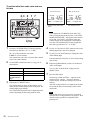
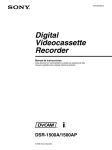
1 Display section
2 INPUT signal display section
3 Time data type indicators
4 DVCAM indicator
5 KEY INHI indicator
6 REC INHI indicator
7 Disk end alarm indicator
8 REPEAT indicator
9 Time counter display
0 Remote mode indicators
qa VITC indicator
qs PB Fs display
qd REC MODE display
1 OUTPUT signal display section
a OUTPUT signal display section
Indicates the output video and audio signal format selected
with the INTERFACE SELECT menu items (see page 72).
This selection determines the signals output from the
Y/CPST, R−Y/S−C, and B−Y/S−Y, SUPER
connectors as follows.
VIDEO indicators: The indicator (COMPOSITE, S
VIDEO, or Y−R,B) corresponding to the selected
output analog video signal format lights.
Indicators
Meanings
COMPOSITE
Composite video signal
S VIDEO
S-video (separated Y and C) signals
Y−R,B
Y, R−Y and B−Y component video
signals
Location and Function of Parts
17
• When COMPOSITE/S VIDEO is selected:
Indicators
Connectors
Output signals
Y/CPST
Composite signal
R−Y/S−C
S−C
B−Y/S−Y
S−Y
SUPER
Composite signal
• When Y–R,B is selected:
Connectors
Output signals
Y/CPST
Y signal
R−Y/S−C
R−Y signal
B−Y/S−Y
B−Y signal
SUPER
Composite signal
AUDIO indicators: Comprise the CH 1/2 indicator and
CH 3/4 indicator to indicate the channel selection for
analog audio output from the AUDIO OUT 1/3 and
AUDIO OUT 2/4 connectors.
Indicators
Functions
CH 1/2
Lights when channels 1 and 2 are
selected for analog audio output from
the AUDIO OUT 1/3 and AUDIO OUT
2/4 connectors.
CH 3/4
Lights when channels 3 and 4 are
selected for analog audio output from
the AUDIO OUT 1/3 and AUDIO OUT
2/4 connectors.
You can change the channel selection with the AUDIO
OUTPUT menu item (see page 72).
b INPUT signal display section
Indicates the input video and audio signal formats selected
with the INPUT SELECT buttons (i.LINK, VIDEO, CH1
1/2, and CH2 3/4 buttons).
i.LINK indicator: Lights when the digital video and audio
signals in i.LINK-compatible DV format are selected.
VIDEO indicators: The indicator (COMPOSITE, S
VIDEO, Y−R,B, SDI, or SG) corresponding to the
selected input video signal format lights.
Indicators
Meanings
COMPOSITE
Composite video signal
S VIDEO
S-video (separated Y and C) signals
Y−R,B
Y, R−Y and B−Y component video
signals
SDI
SDI video signal
SG
Video test signal (factory default
setting)
AUDIO indicators: Comprise the CH-1 1/2 indicator and
CH-2 3/4 indicator, under each of which there are four
more indicators (ANALOG, AES/EBU, SDI, and SG).
They indicate the selected input audio signal formats.
18
Location and Function of Parts
Functions
CH-1 1/2
The indicator corresponding to the
(ANALOG, AES/ signal format selected for audio input
EBU, SDI, SG) to channel 1 (when in 2-channel
mode) or to channels 1 and 2 (when
in 4-channel mode) lights.
ANALOG: Analog audio signal
AES/EBU: Digital audio signal in
AES/EBU format
SDI: SDI audio signal
SG: Audio test signal (factory default
setting)
CH-2 3/4
The indicator corresponding to the
(ANALOG, AES/ signal format selected for audio input
EBU, SDI, SG) to channel 2 (when in 2-channel
mode) or to channels 3 and 4 (when
in 4-channel mode) lights.
ANALOG: Analog audio signal
AES/EBU: Digital audio signal in
AES/EBU format
SDI: SDI audio signal
SG: Audio test signal (factory default
setting)
Note
The indicators blink if no signals are connected to the
selected video/audio input connectors.
c Time data type indicators
One of the three indicators (COUNTER, U-BIT, or TC)
lights to indicate the type of time data currently shown in
the time counter display.
COUNTER: Count value of the time counter
U-BIT: User bit data
TC: SMPTE time code (for DSR-DR1000) or EBU time
code (for DSR-DR1000P)
d DVCAM indicator
This stays lit.
e KEY INHI (key inhibit) indicator
Lights when the control mode selection switch is set to
KEY INHI.
f REC INHI (recording inhibit) indicator
Lights when the REC INHIBIT menu item (see page 65) is
set to ON.
g Disk end alarm indicator
Starts flashing when the remaining capacity of the disk is
for about 2 minutes.
h REPEAT (repeat playback) indicator
Lights when the REPEAT MODE menu item (see page
64) is set to ON to enable the repeat playback function.
i Time counter display
Indicates the count value of the time counter, time code,
VITC, or user bit data depending on the settings of the
COUNTER SELECT button and the TC SELECT menu
item (see page 68).
Also used to display error messages, edit data, setup menu
data, etc.
j Remote mode indicators
REMOTE: Lights when the Control mode selector is set
to REMOTE to remote control the unit from either an
editing control unit connected to the REMOTE IN (R)/
OUT (P) connectors or equipment connected to the
S400(i.LINK) connector.
9P: Lights when the REMOTE I/F menu item (see page
72) is set to 9PIN.
i.LINK: Lights when the REMOTE I/F menu item (see
page 72) is set to i.LINK.
k VITC indicator
Lights when VITC is being read or recorded regardless of
the data shown in the time counter display.
l PB Fs (playback audio sampling frequency) display
During playback, this indicates the playback audio mode
in which the disk being played back was recorded.
48K indicator: Lights during playback of material
recorded in 2-channel mode (48 kHz).
32K indicator: Lights during playback of material
recorded in 4-channel mode (32 kHz).
m REC MODE (audio recording mode) display
This indicates the audio recording mode currently selected
with the REC MODE menu item (see page 71).
2CH indicator: Lights in 2-channel mode (48 kHz).
4CH indicator: Lights in 4-channel mode (32 kHz).
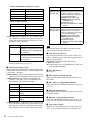
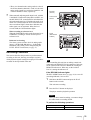
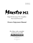
2 Video/audio input setting section
INPUT SELECT
CH1 1/2
CH2 3/4
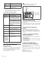
• Video test signal (selected with the INT VIDEO SG
menu item (see page 69) generated by the internal signal
generator
• Digital video/audio signal (DV format, complied with
i.LINK) connected to the S400(i.LINK) connector
The selection made with this button is indicated by the
VIDEO indicators in the INPUT signal display section (see
page 18).
Note
When the video input is set to the i.LINK, pressing either
the CH1 1/2 button or CH2 3/4 button changes the setting
to COMPOSITE. Reset the video input.
b CH1 1/2 (audio channel 1 or 1/2) button
Each press of this button cycles through the following
input audio signal selection options for audio channel 1
(when in 2-channel mode) or for audio channels 1 and 2
(when in 4-channel mode).
• Analog audio signal input to the AUDIO IN 1/3
connector
• Digital audio signal in AES/EBU format input to the
AUDIO (AES/EBU) IN 1/2 connector
• SDI audio signal input to the SDI IN connector
• Audio test signal (selected with the INT AUDIO SG
menu item (see page 72) generated by the internal signal
generator
The selection made with this button is indicated by the
AUDIO CH-1 1/2 indicators in the INPUT signal display
section (see page 18).
When analog audio is selected, the signal input to the
AUDIO IN 1/3 connector is recorded either on channel 1
(when in 2-channel mode) or on channels 1 and 3 (when in
4-channel mode). That is, in 4-channel mode, the same
analog audio signal is recorded on channels 1 and 3. Using
the REC/PB LEVEL control knobs with the VARIABLE
switch set to REC, it is possible to adjust the audio levels
on the two channels separately.
You can switch the audio recording mode with the REC
MODE menu item (see page 71). The selection is indicated
by the REC MODE display on the front panel.
3 CH2 3/4 button
2 CH1 1/2 button
1 VIDEO button
a VIDEO button
Each press of this button cycles through the following
input video signal selection options.
• Composite video signal input to the VIDEO IN
connector
• S-video (separated Y and C) signals input to the VIDEO
IN connectors
• Y, R−Y and B−Y component video signals input to the
VIDEO IN connectors
• SDI video signal input to the SDI IN connector
c CH2 3/4 (audio channel 2 or 3/4) button
Each press of this button cycles through the following
input audio signal selection options for audio channel 2
(when in 2-channel mode) or for audio channels 3 and 4
(when in 4-channel mode).
• Analog audio signal input to the AUDIO IN 2/4
connector
• Digital audio signal in AES/EBU format input to the
AUDIO (AES/EBU) IN 3/4 connector
• SDI audio signal input to the SDI IN connector
• Audio test signal (selected with the INT AUDIO SG
menu item (see page 72) generated by the internal signal
generator
Location and Function of Parts
19
The selection made with this button is indicated by the
AUDIO CH-2 3/4 indicators in the INPUT signal display
section (see page 18).
When analog audio is selected, the signal input to the
AUDIO IN 2/4 connector is recorded either on channel 2
(when in 2-channel mode) or on channels 2 and 4 (when in
4-channel mode). That is, in 4-channel mode, the same
analog audio signal is recorded on channels 2 and 4. Using
the REC/PB LEVEL control knobs with the VARIABLE
switch set to REC, it is possible to adjust the audio levels
on the two channels separately.
You can switch the audio recording mode with the REC
MODE menu item (see page 71). The selection is indicated
by the REC MODE display on the front panel.
Note
If you set the VARIABLE switch to REC, set the audio
input levels, and then set the switch to PB, the audio input
levels return to the preset levels. In the same way if you set
VARIABLE switch to PB, set the audio output levels, and
then set the switch to REC, the audio output levels return
to the preset levels.
b REC/PB LEVEL control knobs
These knobs are used to control audio levels function
differently depending on the setting of the VARIABLE
switch as follows.
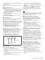
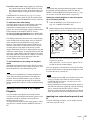
3 Audio input/output level control section
VARIABLE
switch
setting
Functions of control knobs
PRESET
Control knobs are not effective.
The analog audio input/output levels are set to
the reference level set with the LEVEL
SELECT menu item (see page 71).
The digital audio input/output levels are not
adjusted.
REC
Control the analog/digital audio input levels on
channels 1 to 4 during recording.
The audio output levels return to the preset
levels.
PB
Control the analog/digital audio output levels
on channels 1 to 4 during playback.
The audio input levels return to the preset
levels.
1 VARIABLE switch
2 REC/PB LEVEL
control knobs
REC/PB LEVEL
VARIABLE
1
2
3
4
REC
PB
PRESET
a VARIABLE switch
Use to switch the way in which the REC/PB LEVEL
control knobs function.
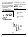
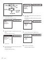
4 Recording/playback control section
REC
PLAY
NEXT
STOP
6 STOP button
5 NEXT button
4 PLAY button
3 PREV button
2 REC button
1 REC indicator
20
Location and Function of Parts
a REC (record) indicator
Lights during recording.
PANEL SELECT
b REC (record) button
When you press this button while holding down the PLAY
button, it lights and recording begins.
R
P
EXT
3 EXT button
Note
When the control mode selector is set to REMOTE (the
REMOTE indicator is lit), no recording/playcack control
buttons other than the STOP button will work. This can be
changed with the LOCAL ENABLE menu item (see page
65).
c PREV (previous) button
When pressed once, moves to the start point of the clip
containing the current position. When pressed a second
time, moves to the start point of the previous clip.
Pressing the PREV button with the PLAY button held
down allows you to view fast reverse playback. However,
to do this, you need to set the F. FWD/REW menu item
under the AUTO EE SELECT menu item (see page 64) to
PB.
If cue points are set (see page 36), the PREV button is used
to cue up a cue point (see page 44).
d PLAY button
When you press this button, it lights and playback begins.
If you press this button during recording, the recording
operation is stopped and this unit enters playback mode.
e NEXT button
When pressed once, moves to the start point of the next
clip. However, when this button is pressed while in the last
clip, it moves to the end point of that clip.
Pressing the NEXT button with the PLAY button held
down allows you to view fast forward playback. However,
to do this, you need to set the F. FWD/REW menu item
under the AUTO EE SELECT menu item (see page 64) to
PB.
If cue points are set (see page 36), the NEXT button is used
to cue up a cue point (see page 44).
f STOP button
Press this button to stop the recording or playback
operation.
2 P button
1 R button
a R (recorder) button
Press this button, turning it on, to put the control panel of
the unit into a state in which the only operations possible
are recording operations. The buttons which function in
this state are the REC button, PLAY button (only when
pressed at the same time as the REC button), and the STOP
button.
b P (player) button
Press this button, turning it on, to put the control panel of
the unit into a state in which the only operations possible
are playback operations. The REC button and PLAY
button do not function, even if pressed at the same time.
c EXT (external) button
When you have connected multiple DSR-DR1000/
DR1000P units in a cascade sequence and want to control
the other units from a one unit, press the EXT button of the
controlling unit, turning it on.
You can connect multiple DSR-DR1000/DR1000P units
for multi-simultaneous playback. For details, see
“Connecting Multiple Units for Simultaneous Playback
(Multi-Simultaneous Playback)” on page 42.
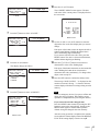
6 Menu/clip control section
1 MENU button
2 RESET button
MENU RESET
3 SET button
CUE
5 PANEL SELECT section
IN
Note
SET
OUT
4 Cursor/clip operation
buttons
The buttons of the PANEL SELECT section cannot be
turned on or off during simultaneous recording and
playback.
Location and Function of Parts
21
a MENU button
Press this button to display the menu on the monitor screen
and the time counter display. Press it again to exit the menu
display.
On how to use the menu, see Chapter 6 “Menu Setting”
See the description of the search dial 4 for more
information about the jog and shuttle modes.
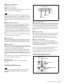
b VAR (variable) button
Press this button, turning it on, to use the search dial for
search playback in variable mode.
b RESET button
Press this button to:
• reset menu settings,
• reset the time data shown in the time counter display to
zero
• send a negative response to the prompts issued by the
unit, or
• delete clips.
See the description of the search dial 4 for more
information about the variable mode.
c SET button
Press this button to:
• save new settings, such as selected menu items and time
code settings, to memory.
• send a positive response to the prompts issued by the
unit, or
• create a clip list.
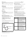
d Search dial
Rotate to perform search playback in jog shuttle, or
variable mode.
The G indicator lights when you rotate to the right to
indicate forward direction playback. The g indicator lights
when you rotate to the left to indicate reverse direction
playback. The s indicator lights when playback is
stopped. The s lights when unit is powered on.
Each press of the search dial toggles between shuttle and
jog mode, or between variable mode and jog mode.
d Cursor/clip operations buttons
Press these buttons to select a menu item, to change
timecode initial values and user bits data, and to set clip in
and out points, and to set cue points.
K (IN): Moves to the left or sets an in point.
J (CUE): Moves up or sets a cue point.
k (OUT): Moves right or sets an out point.
j: Moves down.
c JOG and SHUTTLE indicators
One of the indicators lights to show the current or most
recent search playback mode.
JOG indicator: Jog mode
SHUTTLE indicator: Shuttle or variable mode.
Search
playback mode
Operation/function
Shuttle
Press the SEARCH button or the search
dial to select shuttle mode (the SHUTTLE
indicator lights). Playback is carried out
at a speed determined by the rotation
angle of the search dial.
The maximum shuttle playback speed
can be changed with the MAX SRCH
SPEED menu item (see page 65).
Jog
Press the SEARCH button or the search
dial to select jog mode (the JOG indicator
lights). Playback is carried out at a speed
determined by the rotation speed of the
search dial. The playback sped range is
±1 times normal speed. The search dial
does not click in this mode.
Variable
Press the VAR button, lighting it (the
SHUTTLE indicator also lights). You can
control fine-grained (in 61 steps)
playback over the range (2 times normal
speed. The search dial clicks in the
positions for still playback, ±1 times
normal speed, and ±2 times normal
speed.
For details on modifying the time code value, see “To set
the initial time code value and user bit data” on page 30.
7 Search control section
1 SEARCH button
2 VAR button
JOG
SEARCH
SHUTTLE
3 JOG and SHUTTLE
indicators
VAR
4 Search dial
a SEARCH button
Press this button, turning it on, to use the search dial for
search playback in jog or shuttle mode.
22
Location and Function of Parts
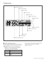
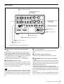
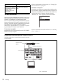
Rear Panel
1 REF. VIDEO IN connectors
1 Analog video/audio signal
input section
(see page 24)
2 Analog video/audio signal
output section
(see page 25)
3 Digital signal input/output
section (see page 26)
2 POWER switch
3 -AC IN connector
4 CONTROL connecter
5 REMOTE IN (R)/OUT (P) connectors
6
400 (i.LINK) connector
7 Network connecter
4 Time code input/output section (see page 26)
a REF. (reference) VIDEO IN connectors (BNC
type)
Input a reference video signal. The two connectors are
loop-through connectors. You can connect the reference
video signal input to the left connector to other equipment
via the right connector (marked
). When no connection
is made to the right connector, the left connector is
terminated with an impedance of 75 Ω automatically.
b POWER (main power) switch
Switch to the ? side to turn the power on. Switch to the a
side to turn the power off. Normally you should leave this
switch in the on position and power the unit on and off with
the power switch on the front panel.
Note
When you power the unit off with the switch on the front
panel, data is saved before the power is cut off. If you need
to turn the main power off, always power the unit off with
the switch on the front panel before setting this switch to
off.
c - AC IN connector
Use the supplied power cord to connect this to an AC
outlet.
d CONTROL connector (mini-jack)
Connect the supplied RM-LG2 Remote Control Unit.
e REMOTE IN (R)/OUT (P) connectors (D-sub 9pin)
You can connect remote control units to these connectors
using an optional 9-pin remote cable. You can also use this
connectors to make cascade connections between several
DSR-DR1000/DR1000P units.
Use the IN(R) connector to connect an editor. When
connecting remote control devices, connect the device that
controls recording operations to the IN(R) connector and
the device that controls playback operations to the OUT(P)
connector.
Before doing this, you need to set the REMOTE I/F menu
item (see page 72) to select how the connectors are used.
Location and Function of Parts
23
f
400 (i.LINK) connector (6-pin IEEE-1394)
Connect a DV cable to make connections to DV devices,
computers, and so on.
Notes
• If the unit is connected to a device equipped with a 6-pin
DV jack, when you intend to disconnect or reconnect the
DV cable, turn off the device and pull out the plug of its
power cord from the AC outlet beforehand. If you
connect or disconnect the DV cable while the device is
connected to the AC outlet, high-voltage current (8 to 40
V) is output from the DV jack of the device to this unit,
which may cause a malfunction.
• When connecting a device that has a 6-pin DV jack to
this unit, first connect the plug of the cable to the 6-pin
DV jack of the device.
• When searching at speeds in the range +1/2 to +1/30 or
−1/30 to −1/2 times normal speed, the audio signal output
from this connector and monitored on external
equipment may sound differently from the audio signal
played back on this unit.
g
(network) connector (RJ-45 type)
This is a 10BASE-T/100BASE-TX connector for network
(Ethernet) connection.
Caution
When using a LAN cable: For safety, do not connect to a
connector for peripheral device wiring that might have
excessive voltage.
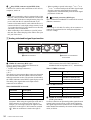
1 Analog video/audio signal input section
VIDEO IN
Y/CPST
R-Y/C
B-Y
1/3
2/4
1 VIDEO IN connectors
a VIDEO IN connectors (BNC type)
There are the following VIDEO IN connectors for
inputting analog video signals:
• Y/CPST (loop-through connectors)
• R−Y/C
• B−Y
The signals you can connect to these connectors depend on
the selection made with the VIDEO button in the video/
audio input selection section. The selection is indicated by
the VIDEO indicators in the INPUT signal display section.
The analog video signals that can be input to these
connectors are as follows.
When COMPOSITE is selected:
2 AUDIO IN 1/3 and AUDIO IN
2/4 connectors
CPST connector, the left Y/CPST connector is
terminated with an impedance of 75 Ω automatically.
When S VIDEO is selected:
Connectors
Input signals
Y/CPST
Y signal
R−Y/C
C signal
(3.58 MHz for DSR-DR1000/
4.43 MHz for DSR-DR1000P)
B−Y
— (not usable)
When Y–R,B is selected:
Connectors
Input signals
Y signal
Connectors
Input signals
Y/CPST
Y/CPST
Composite signal
R−Y/C
R−Y signal
R−Y/C
— (not usable)
B−Y
B−Y signal
B−Y
— (not usable)
The two Y/CPST connectors are loop-through
connectors. When using the signal input to the left Y/
CPST connector as a reference video signal, for
example, you can bridge-connect the signal to other
equipment via the right Y/CPST connector (marked
). When no connection is made to the right Y/
24
AUDIO IN
Location and Function of Parts
b AUDIO IN 1/3 and AUDIO IN 2/4 connectors
(XLR-3 pin, female)
Use these connectors to input analog audio signals from an
external video cassette player or other audio equipment.
The signals input to these connectors are recorded on the
audio channels determined by the current audio recording
mode, as follows.
When in 2 CH (48 kHz) mode:
Input
connectors
Audio channels on which input
signals are recorded
AUDIO IN 1/3
Audio channel 1
AUDIO IN 2/4
Audio channel 2
Input
connectors
Audio channels on which input
signals are recorded
AUDIO IN 1/3
Audio channels 1 and 3
AUDIO IN 2/4
Audio channels 2 and 4
You can switch the audio recording mode with the REC
MODE menu item (see page 71). The selection is indicated
by the REC MODE display on the front panel.
When in 4 CH (32 kHz) mode:
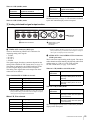
2 Analog video/audio signal output section
VIDEO OUT
Y/CPST
R-Y/S-C
B-Y/S-Y
1/3
2/4
AUDIO OUT
SUPER
MONITOR
3 MONITOR
connector
1 VIDEO OUT connectors
a VIDEO OUT connectors (BNC type)
There are the following VIDEO OUT connectors for
outputting analog video signals:
• Y/CPST
• R−Y/S−C
• B−Y/S−Y
• SUPER
The signals output from these connectors depend on the
setting of the VIDEO OUTPUT menu item (see page 72).
The setting is indicated by the VIDEO indicators in the
OUTPUT signal display section on the front panel.
The analog video signals that can be output from these
connectors are as follows.
When COMPOSITE/S VIDEO is selected:
Connectors
Output signals
Y/CPST
Composite signal
R−Y/S−C
S−C
B−Y/S−Y
S−Y
SUPER*
Composite signal
* When the CHARA. DISPLAY menu item (see page 66) is set to ON
(factory default setting), the SUPER connector outputs a composite
video signal with superimposed text information.
When Y–R, B is selected:
Connectors
Output signals
Y/CPST
Y signal
R−Y/S−C
R−Y signal
B−Y/S−Y
B−Y signal
SUPER*
Composite signal
2 AUDIO OUT 1/3 and
AUDIO OUT 2/4
connectors
* When the CHARA. DISPLAY menu item (see page 66) is set to ON
(factory default setting), the SUPER connector outputs a composite
video signal with superimposed text information.
b AUDIO OUT 1/3 and AUDIO OUT 2/4 connectors
(XLR-3 pin, male)
These connectors output analog audio signals. The output
audio channels are determined by the playback audio mode
and the setting (1/2 CH or 3/4 CH) of the AUDIO
OUTPUT menu item (see page 72) as follows.
When in 2 CH (48 kHz or 44.1 kHz) mode:
Output
connectors
Output audio channels
AUDIO OUT 1/3 Audio channel 1 (when 1/2 CH is
selected) or silent (when 3/4 CH is
selected)
AUDIO OUT 2/4 Audio channel 2 (when 1/2 CH is
selected) or silent (when 3/4 CH is
selected)
When in 4 CH (32 kHz) mode:
Output
connectors
Output audio channels
AUDIO OUT 1/3 Audio channel 1 (when 1/2 CH is
selected) or audio channel 3 (when 3/
4 CH is selected)
AUDIO OUT 2/4 Audio channel 2 (when 1/2 CH is
selected) or audio channel 4 (when 3/
4 CH is selected)
The current playback audio mode is indicated by the PB Fs
display on the front panel.
Location and Function of Parts
25
c MONITOR connector (RCA phono jack)
This connector outputs audio signals for monitoring. The
audio signals to be output from this connector can be
selected with the MONITOR SELECT button and
METER CH-1/2 3/4 button on the front panel (see page
15).
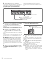
3 Digital signal input/output section
DIGITAL AUDIO
1/2 - IN - 3/4
SDI
(AES/EBU)
1/2 - OUT - 3/4
IN
OUT1
OUT2
4 SDI OUT1/OUT2 connectors
3 SDI IN connector
2 DIGITAL AUDIO (AES/EBU) OUT 1/2 and
AUDIO (AES/EBU) OUT 3/4 connectors
1 DIGITAL AUDIO (AES/EBU) IN 1/2 and AUDIO
(AES/EBU) IN 3/4 connectors
a DIGITAL AUDIO (AES/EBU) IN 1/2 and AUDIO
(AES/EBU) IN 3/4 connectors (BNC type)
Input digital audio signals in AES/EBU format to these
connectors.
The left connector (1/2) is for audio channels 1 and 2, and
the right connector (3/4) is for audio channels 3 and 4.
b DIGITAL AUDIO (AES/EBU) OUT 1/2 and
AUDIO (AES/EBU) OUT 3/4 connectors (BNC
type)
These connectors output digital audio signals in AES/EBU
format.
The left connector (1/2) is for audio channels 1 and 2, and
the right connector (3/4) is for audio channels 3 and 4.
c SDI IN (Serial Digital Interface input) connector
(BNC type)
This connector inputs digital video and audio signals in
SDI format. Use the VIDEO button in the video/audio
input setting section (see page 19) to select the required
input signal formats. The current input signal selections
are indicated in the INPUT signal display section (see page
18).
d SDI OUT1/OUT2 (Serial Digital Interface output
1/output 2) connectors (BNC type)
These connectors output digital video and audio signals in
SDI format.
26
Location and Function of Parts
D Time code input/output section
1 TIME CODE IN connector
2 TIME CODE OUT connector
IN TIME CODE OUT
a TIME CODE IN (time code input) connector (BNC
type)
Input externally generated SMPTE time code (for DSRDR1000) or EBU time code (for DSR-DR1000P) to this
connector.
b TIME CODE OUT (time code output) connector
(BNC type)
This connector outputs a time code according to the
operating state of the unit, as follows:
During playback: the playback time code
During recording: the time code generated by the internal
time code generator or the time code input to the TIME
CODE IN connector. When the EE OUT PHASE
menu item (see page 69) is set to MUTE, no time code
is output.
Preparations
Setting the Date and Time
When you start this unit for the first time, you should set
the data and time. To set the date and time, use the DATE/
TIME PRESET menu.
See page 75 for more information about basic menu
operations.
DATE/TIME PRESET
DATE 2002/07/10
TIME 18:29:10
INC/DEC
SHIFT
CLEAR
DATA SAVE
TO MENU
: ( )( )KEY
: ( )( )KEY
: RESET KEY
:
SET KEY
: MENU KEY
Chapter
2
To change a numeric value
Press the J(CUE) button to increase a value. Press the j
button to decrease a value.
To return a value to the factory default setting (2002/01/01
00: 00: 00) press the RESET button.
To confirm a value
Press the SET button.
To exit the date and time setting menu without changing
any values, press the MENU button.
To display the material’s recording date
and time on the monitor
This unit records time code and the recording date and time
together with video data. To the material's recording date
and time on the monitor, set the DISPLAY INFO menu
item (see page 66) to REC DATE&TIME.
Setting the Time Data
To select the digit to set
Press the K(IN) or k(OUT) button until the digit you
want to change starts flashing. (In the date display, the
digit in the second place from the left does not flash).
To move from the date display to the time display, press
the k(OUT) button while the rightmost digit is flashing
(the leftmost digit of the time display begins to flash), or
press the K(IN) button while the third place from the left
(the + position) is flashing (the rightmost digit of the time
display begins to flash).
To move from the time display to the date display, press
the k(OUT) button while the rightmost digit is flashing
(the third place of the date display begins to flash), or press
the K(IN) button while the leftmost digit is flashing (the
rightmost digit of the date display begins to flash).
This unit is provided with the following functions related
to time data.
• Display and reset CNT value
• Set, display, record, and play back SMPTE/EBU time
code and user bit data
• Set, display, record, and play back VITC
The unit can output the time code read from the disk as an
analog (LTC) signal, and receive an external analog time
code (LTC) signal.
Note
The unit outputs no signal from the TIME CODE OUT
connector unless it is in normal-speed playback mode.
The following explains how to use these functions.
Setting the Date and Time / Setting the Time Data
27
Displaying Time Data and Operation
Mode Indications
Indication
Description
CNT
Count value of the time counter
TCR
Time code data from time code reader
(factory default setting)
UBR
User bit data from time code reader
TCR.
Time code data from VITC reader a)
UBR.
User bit data from VITC reader a)
To view time data and operation mode
indications on the monitor screen
TCG
Time code data from time code generator
UBG
User bit data from time code generator
Set the CHARA. DISPLAY menu item (see page 66) to
ON (factory default setting).
The time data and the indication of the current operation
mode are superimposed on the video signal that is being
output from the SUPER connector, and can be viewed on
the monitor screen.
Use the DISPLAY CONTROL menu items (see page 66)
to select the information displayed and the character type
and position of the indications.
T*R b)
Time code data from time code reader. The
asterisk indicates an interpolation by the time
code reader to make up for the time code
data not correctly read from the disk.
U*R b)
User bit data from the time code reader. The
asterisk indicates that last data is retained by
the time code reader, as the new data has
not been read correctly from the disk.
Time data and operation mode indications can be
displayed on the monitor screen.
Time data can also be displayed in the time counter display
on this unit.
When you set the SUB STATUS menu item (see page 67)
to other than OFF, you can also display supplementary
status information on the monitor screen such as the
operating mode of the internal time code generator.
For details of supplementary status information, see
“Displaying Supplementary Status Information” on page
79.
Monitor screen contents
The contents of the monitor screen are shown below.
A Time data type
a) You can switch between TC and VITC using the TC SELECT menu item
(see page 68).
b) “*” is displayed when data cannot be read in correctly.
B Drop frame indication for time code reader (on
DSR-DR1000 only)
.
Drop frame mode (factory default setting)
:
Non-drop frame mode
C Drop frame indication for time code generator
(for DSR-DR1000 only)
.
Drop frame mode (factory default setting)
:
Non-drop frame mode
Time data
B Drop frame indication
for time code reader a)
C Drop frame indication for
time code generator a)
D VITC field
indication
T C R
0 0 : 0 4 . 4 7 . 0 7 *
P L A Y
F Recording indications during
simultaneous playback and recording
E DSR-DR1000/DR1000P operation mode
a) This character (.) can appear on the DSR-DR1000 only. The
character to appear in these two columns is always a colon
( : ) on the DSR-DR1000P.
A Time data type
The following time data type indications are displayed.
28
Setting the Time Data
D VITC field indication
(blank)
Display fields 1 and 3.
*
Display fields 2 and 4.
E DSR-DR1000/DR1000P operation mode
Display
Operation mode
STOP
Stop mode
F. FWD
Fast forward mode
REW
Rewind mode
PREROLL
Preroll mode
PLAY
Playback mode (servo unlocked)
PLAY-PAUSE
Temporary stop of playback
PLAY LOCK
Playback mode (servo locked)
REC
Record mode (servo unlocked)
Display
Operation mode
REC-PAUSE
Temporary stop of recording
REC LOCK
Time data shown in the time counter
display
Record mode (servo locked)
Time data
type
indicator
JOG STILL
Still picture in jog mode
COUNTER
CNT (count value of the time counter)
JOG FWD
Jog mode in forward direction
TC
JOG REV
Jog mode in reverse direction
SHUTTLE (Speed)
Shuttle mode
Time code (when recording, the time code is
generated by the internal time code
generator; when playing back, the time code
is read from the disk.)
VAR (Speed)
Variable mode
U-BIT
PLAY (Deviation from
normal speed (%))
Tape speed override (TSO) mode
User bit data (when recording, the user bit
data is according to the most recent settings;
when playing back, the user bit data is read
from the disk.)
F Recording indications during
simultaneous playback and recording*
(blank)
(white rectangle)
Indicates that recording is not being
done.
Indicates that recording is being
done.
* Displayed only during simultaneous recording and playback mode (when
the R button or P button in the PANEL SELECT section is lit, or when the
REMOTE I/F menu item (see page 72) is set to 9PIN(DUAL).
To display the desired time data in the time
counter display
Time data type indicators
Note
When the REMOTE indicator in the front panel display
section is lit, the COUNTER SELECT button does not
operate during recording or playback. In such cases, use
the external equipment connected to the REMOTE IN (R)/
OUT (P) connector on the rear panel to select the time data.
To reset the CNT value
Press the RESET button in the menu control section. This
resets the CNT value to 0:00:00:00.
Using the Internal Time Code
Generator
You can set the initial time code value before recording the
time code generated by the internal time code generator
onto a disk. In addition, you can use the user bits to record
such data as the date, time, scene number, or other useful
information.
When an external time code generator is connected to the
TIME CODE IN connector, the internal time code
generator can be locked to (synchronized with) an external
time code.
COUNTER SELECT button
Time counter display
Press the COUNTER SELECT button on the front panel.
Each press of this button cycles through three options:
CNT value, time code, and user bit data. The time data type
indicator for each option lights as it is selected.
Setting the Time Data
29
To set the initial time code value and user
bit data
2,3 6 1 7
TC PRESET MODE
UB PRESET MODE
TCG 00:00:00:00
UBG 00:00:00:00
INC/DEC : ( )( )KEY
SHIFT : ( )( )KEY
CLEAR : RESET KEY
DATA SAVE :
SET KEY
ABORT : TC PRESET KEY
INC/DEC : ( )( )KEY
SHIFT : ( )( )KEY
CLEAR : RESET KEY
DATA SAVE :
SET KEY
ABORT : TC PRESET KEY
Initial time code value setting
screen
User bit setting screen
Note
If you display the TC PRESET menu while CNT
value is being displayed, the message “COUNTER
MODE IS SELECTED.” will appear on the monitor
screen and “CNT mode!” will appear in the time
counter display on the front panel. If this happens,
press the COUNTER SELECT button to light the
time data type indicator “TC” or “U-BIT.”
4,5,6
1
2
3
4
Use the K (IN) and k (OUT) buttons to move the
flashing digit to the value to be changed.
TC: To set the initial time code value
U-BIT: To set user bit data
The current time code value or user bit data is shown
in the time counter display.
5
Use the J (CUE) and j buttons to change the value
of the flashing digit.
Set the TIME CODE menu items (see page 68) as
shown below.
6
Press the COUNTER SELECT button to light the
time data type indicator “TC” or “U-BIT.”
Menu item
Setting
TC MODE
“INT PRESET”
RUN MODE
“FREE RUN” or “REC RUN”
DF MODE
(for DSR-DR1000
only)
Normally “ON (DF)”
Display the TC PRESET menu.
The current setting is shown on the monitor screen
and in the time counter display on the front panel. The
leftmost digit keeps flashing.
One of the following menu screens is displayed on the
monitor depending on the setting made in step 1.
Enter hexadecimal values (0 to 9, A to F) when setting
user bit data.
Repeat steps 4 and 5 until you have set the desired
values for all digits.
To set a value of 00:00:00:00, simply press the
RESET button.
7
Press the SET button.
The message “NOW SAVING...” appears on the
monitor screen, “Saving...” appears in the time
counter display, and the new settings are stored in
memory.
After this saving operation is completed, the monitor
screen and the time counter display return to their
usual status.
Note
The set data may be lost if you power off the unit
while the above saving operation is in progress. Wait
until the saving operation is completed before
powering off.
30
Setting the Time Data
Advancement of internal time code
generator
The internal time code generator can advance in either of
two modes, which can be set with the RUN MODE menu
item (see page 68).
FREE RUN: Advancement starts when the data saving
operation is completed.
REC RUN: Advancement starts when recording starts and
stops when recording stops.
To confirm external synchronization
Press the STOP button to put the unit into stop mode, then
press the REC button.
Look at the time counter display and check that the time
code value displayed there matches the external time code
value.
To set the current time as the initial time
code value
In step 2 above, set the RUN MODE menu item to FREE
RUN, then set the current time (format: HH:MM:SS:FF =
hours: minutes:seconds:frame number) in step 3 and
subsequent steps.
Synchronizing Internal and External
Time Codes
The internal time code generator can be synchronized with
an external time code (LTC) input to this unit.
To synchronize the internal time code to
external time code
Input an external time code (LTC) signal to the TIME
CODE IN connector, then set the TC MODE menu item
(see page 68) to EXT REGEN.
The internal time code generator locks onto the external
time code and starts advancing. Once the internal time
code generator has been synchronized in this way, you can
disconnect the external time code input and this unit will
maintain the synchronized time code.
Note
When the selected input mode is “i.LINK” (the i.LINK
indicator is lit in the INPUT signal display section), setting
the TC MODE menu item to EXT REGEN causes the
internal time code generator to automatically synchronize
with the external time code input to the unit via the i.LINK
interface.
When the TC SELECT menu item is set to VITC, the
internal time code generator synchronizes to the time code
(VITC) of video input signals.
Once an external time code signal has been input, the
internal time code advancement mode and frame count
mode are automatically set as follows:
Advancement mode: FREE RUN
Frame count mode: Same as external time code (drop
frame or non-drop frame)
Setting the Time Data
31
Making Basic Network
Settings
To use this unit in a LAN environment (see page 51), you
need to set this unit’s IP address, subnet mask, and default
gateway, and to set up an account with a user name and
password. Use the NETWORK CONTROL menu to make
these basic network settings.
For the IP address, subnet mask, and default gateway
values to use, contact the administrator of your LAN.
For more information about basic menu operations, see
page 75.
NETWORK CONTROL
IP ADDRESS
SUB NET MASK
DEFAULT GATEWAY
ACCOUNT
To Set the Subnet Mask
Select SUB NET MASK in the NETWORK CONTROL
screen and press the k(OUT) button.
The default value 255.255.255.000 appears, with the
leftmost digit 2 flashing. Change the value by using the
menu and clip operation buttons in the same way as with
the IP address.
To Set the Default Gateway
Select DEFAULT GATEWAY in the NETWORK
CONTROL screen and press the k(OUT) button.
The default value 000.000.000.000 appears, with the
leftmost digit 0 flashing. Change the value by using the
menu and clip operation buttons in the same way as with
the IP address.
To Set Up a User Account
Select ACCOUNT in the NETWORK CONTROL screen
and press the k(OUT) button. A screen for the user name
and password appears.
Enter a user name and password (up to 8 characters each).
To enter the user name
Select USERNAME and press the k(OUT) button.
A user name screen appears and the cursor begins to flash.
Note
When you have finished making all the settings, power this
unit off and reboot it. The settings made in the NETWORK
CONTROL menu will be enabled when the unit reboots.
To enter characters
Rotate the search dial until the desired character appears.
Characters appear in the following order when the search
dial is rotated in the clockwise direction.
To Set the IP Address
A to Z, [, ], ^, -, `, a to z, {, |, }, ~, !, ", #, $, %, &, ', (, ), *,
+, –, ., /, 0 to 9, :, ;, <, =, >, ?, @
Select IP ADDRESS in the NETWORK CONTROL
screen and press the k(OUT) button.
The default value 127.000.000.01 appears, with the
leftmost digit 1 flashing. Change the value by using the
menu and clip operation buttons.
Characters appear in the reverse order when the search dial
is rotated in the counterclockwise direction.
To delete a character that you have entered, press the
RESET button.
To select the digit to change
Press the K(IN) or k(OUT) button until the digit that
you want to change starts flashing.
32
To move the cursor
Press the K(IN) or k(OUT) button.
To confirm the user name
Press the SET button.
To exit without setting a user name, press the MENU
button.
To change a numeric value
Press the J(CUE) button to increase a value and the j
button to decrease a value.
To return to the value 000.000.000 press the RESET
button.
To enter a password
To confirm the IP address
Press the SET button.
To exit without changing the IP address press the MENU
button.
Select PASSWORD and press the k(OUT) button.
A password screen appears with the cursor flashing. Use
the menu and clip operation buttons to enter a password
and confirm it, in the same way as the user name.
Making Basic Network Settings
Recording and Playback
Chapter
3
Settings for Recording
Recording
Use the following procedure to make normal recording
settings on this unit connected with a player. To perform
normal recording, you need to set the REC MODE menu
item (see page 71) to NORMAL REC.
In addition to normal recording, this unit is capable of
continuous recording (see page 37), interval recording (see
page 37), and pre-alarm recording (see page 37).
This section describes the necessary settings and
operations to perform recording on this unit. The same
settings and operations apply whether you are using the
unit as part of an editing system, for dubbing, or as a standalone recorder.
For the necessary connections for recording and the
settings not covered in this section, see Chapter 7
“Connections and Settings.”
Control mode selector
Audio level meters
INPUT signal display section
5
3
4
6
7
Recorder (this unit)
dB
0
1
OVER
dB
0
-12
-12
-20
-20
-30
-40
-30
-40
-60
-60
CH- 1 3
CH- 2 4
REW
Video monitor
OVER
INPUT
VIDEO
AUDIO
V:SDTI COMPOSITE CH-1 1/2 CH-2 3/4
SDTI
S VIDEO ANALOG ANALOG
i.LINK
AES/EBU AES/EBU
Y-R,B
SDI SG SDI SG SDI SG
OUTPUT
VIDEO
SDI
SDTI
COMPOSITE
S VIDEO
Y-R,B
PLAY
CL REC INHI
U-BIT
SERVO
TC
COUNTER
NO EDIT
REPEAT
AUDIO
CH 1/2
CH 3/4
HOURS
MINUTES
PB FS
48K 44.1K 32K
REC MODE
2CH 4CH
F FWD
STOP
SECONDS
VITC
EDIT MODE
FRAMES
REMOTE
9P i.LINK
2
REC
Player (DSR-1500A/1500AP)
Recording
33
When controlling this unit from an editing control unit
connected to the REMOTE IN (R)connector, see “Control
mode selector” on page 15 and the description of the
REMOTE I/F menu item on page 72.
1
2
Power on the video monitor, then set its input
switches according to the signals input from the
player.
Set up the player to play back a tape.
Power on this unit by pressing the 1 switch on the
front panel.
4
When the REMOTE indicator is off (the external
editing control unit is not used), use the COUNTER
SELECT button to select the type of time data to be
used.
Each press of this button cycles through three options:
COUNTER (CNT value), TC (time code), and U-BIT
(user bit data). The time data type indicator for each
option lights as it is selected.
Selected time data
Time data type indicator
Count value of the time
counter
COUNTER
Time code
TC
User bit data
U-BIT
34
SDI signal
(SDI IN)
VIDEO
SDI in VIDEO
group
i.LINK
Internal test video
signal
VIDEO
Audio input signal
(input connector)
Corresponding Lit indicator
INPUT SELECT in the INPUT
button
signal display
section
Analog signal
(AUDIO IN 1/3 and
AUDIO IN 2/4)
CH1 1/2 and
CH2 3/4
ANALOG in
AUDIO group
AES/EBU signal
(AUDIO (AES/EBU)
IN)
CH1 1/2 and
CH2 3/4
AES/EBU in
AUDIO group
SDI signal
(SDI IN)
CH1 1/2 and
CH2 3/4
SDI in AUDIO
group
i.LINK-compatible
automatic
digital audio signal in setting
DV format
depending on
video input
( S400(i.LINK))
signals
Internal test audio
signal
When the REMOTE indicator is lit, selection of the
time data type is carried out at the editing control unit.
Select the formats of video and audio input signal to
be recorded.
Use the INPUT SELECT buttons in the video/audio
input setting section to select the desired signal
formats. Each selection is shown by a lit indicator in
the INPUT signal display section.
Corresponding
INPUT
SELECT
button
Lit indicator
in the INPUT
signal display
section
( S400(i.LINK))
3
Video input signal
(input connector)
Corresponding
INPUT
SELECT
button
i.LINK-compatible
VIDEO
digital video signal in
DV format
For details, refer to the operating instructions for the
player.
5
Video input signal
(input connector)
CH1 1/2 and
CH2 3/4
SG in VIDEO
group
i.LINK
SG in AUDIO
group
Caution
Once you have started recording, you cannot change
the input signal selection.
6
Select the audio mode.
Select either two-channel mode (2 CHANNEL) or
four-channel mode (4 CHANNEL) with the REC
MODE menu item (see page 71). The corresponding
indicator lights in the REC MODE display.
Lit indicator
in the INPUT
signal display
section
Audio mode
Lit indicator in the REC MODE
display
2-channel mode
2CH
Composite signal
VIDEO
(VIDEO IN: Y/CPST)
COMPOSITE
in VIDEO
group
4-channel mode
4CH
Separated Y/C
signal
(VIDEO IN: Y/CPST
and R−Y/S−C)
VIDEO
S VIDEO in
VIDEO group
Component signal
VIDEO
(VIDEO IN: Y/CPST,
R−Y/S−C, and B−Y/
S−Y)
Y−R,B in
VIDEO group
Recording
Cautions
• Two audio recording modes, with either two
channels at 48 kHz or four channels at 32 kHz, can
be used on this unit. It is not possible to select any
other mode (for example with four channels at 48
kHz).
• If there is a point where the audio mode is switched,
it is not possible to carry out insert editing over a
section including that point.
• When, in 4-channel mode, analog audio is selected
for all four channels (channels 1/2 and 3/4), the same
analog audio signals are recorded on channels 1 and
3 and on channels 2 and 4, respectively.
7
Recorder
(this unit)
When manually adjusting audio input levels, with the
VARIABLE switch on the front panel set to REC, use
the REC/PB LEVEL control knob for each channel to
adjust the audio input level. Watching the audio level
meter in E-E mode, adjust the level so that the meter
does not indicate higher values than 0 dB when the
audio signal is at its maximum. When the level
exceeds 0 dB, the OVER indicator lights.
Control mode
selector
1
When recording at reference level
When the VARIABLE switch on the front panel is set
to PRESET, recording is carried out at the preset
reference level.
Player
(DSR-1500A/
1500AP)
Reference level setting
The factory-preset reference level for analog audio
input is −20 dB (DSR-DR1000) or −18 dB (DSRDR1000P). This setting can be changed using the
LEVEL SELECT menu item (see page 71).
dB
0
OVER
dB
0
-12
-12
-20
-20
-30
-40
-30
-40
OVER
-60
-60
CH- 1 3
CH- 2 4
INPUT
SDI
SDTI
REW
COMPOSITE
S VIDEO
Y-R,B
AUDIO
PLAY
CL REC INHI
U-BIT
SERVO
TC
COUNTER
NO EDIT
REPEAT
AUDIO
CH 1/2
CH 3/4
HOURS
MINUTES
PB FS
48K 44.1K 32K
REC MODE
2CH 4CH
F FWD
SECONDS
VITC
EDIT MODE
STOP
FRAMES
REMOTE
9P i.LINK
REC
2
Recording Procedure
This section describes the procedure to perform normal
recording on this unit, showing an example session in
which playback signals coming from a player VCR will be
recorded on the tape loaded in the unit.
VIDEO
V:SDTI COMPOSITE CH-1 1/2 CH-2 3/4
SDTI
S VIDEO ANALOG ANALOG
i.LINK
AES/EBU AES/EBU
Y-R,B
SDI SG SDI SG SDI SG
OUTPUT
VIDEO
Note
When controlling this unit from an editing control unit
connected to the REMOTE IN (R) connector of this unit,
set the Control mode selector to REMOTE, turning the
REMOTE indicator on. When not, set the switch to
LOCAL, turning the indicator off.
If the REC INHI indicator lights:
The REC INHIBIT menu item (see page 65) is set to ON
(recording inhibited). Set it to OFF.
1
Hold down the REC button and press the PLAY
button on the recorder.
This unit starts recording.
2
Press the PLAY button on the player.
The player starts the playback operation.
Caution
Once you have started recording, you cannot change
the audio mode or recording format.
To perform the following operations
Operation
Do this:
Stop recording.
Press the STOP button.
Recording
35
Operation
For more information on this operation, see “Cueing Up a
Desired Cue Point” on page 44.
Do this:
Inhibit the SUPER
Set the CHARA. DISPLAY
connector from outputting menu item (see page 66) to
text information (time data, OFF.
operation mode
indications, etc.) to the
video monitor.
To delete a cue point
Cue up the cue point that you want to delete, hold down the
J(CUE) button, and press the RESET button. To delete all
cue points, select DELETE ALL CUE from the Disk menu
and press the k(OUT) button. When the message
“DELETE ALL CUE?” appears, press the SET button.
To Set Cue Points
DISK MENU
DELETE
PROTECT
DELETE ALL CUE
Setting cue points at highlight scenes makes it easy to cue
those scenes up later. Cue points can be set in recording,
playback or simultaneous recording and playback.
To set a cue point while recording, hold down the J(CUE)
button and press the SET button at the desired scene. The
message “CUE SET” appears on the monitor screen when
a cue point is set (“Cue Set” in the time counter).
When using a supplied RM-LG2, you can set a cue point
by pressing the CUE button on the RM-LG2.
To cue up a cue point
Hold down the J(CUE) button and press the NEXT/PREV
button to cue up a cue point.
For more information about the Disk menu, see “Deleting
Clips” on page 45
Long-time Recording With Video Camera
The figure below shows connections between this unit and
a video camera.
Reference video
signals
Video camera
a)
Composite video output
a)
Y/CPST
REF. VIDEO IN
a) SUPER
This unit
Video monitor
a) 75 Ω coaxial cable
36
Recording
Recording Continuously by
Overwriting Old Content
(Continuous Recording)
Continuous recording allows you to continue recording for
extended periods by overwriting older recorded content.
To perform continuous recording, you need to set the REC
MODE menu item (see page 65) to CONT. REC. The
CONTINUOUS REC indicator lights when this unit is in
continuous recording mode.
Notes
• Existing clips on the disk are not overwritten in
continuous recording. If you wish to use the entire disk
for continuous recording, delete all clips on the disk
before starting to record.
• In simultaneous recording and playback during
continuous recording, only clips which have been saved
to disk before the start of continuous recording can be
played back. (The clip currently being recorded cannot
be played back.)
Playback
This section describes the settings and operations
necessary to perform playback on this unit. The same
settings and operations apply whether you are using the
unit as part of an editing system, for dubbing, or as a standalone player VCR.
For the necessary connections for playback and the
settings not covered in this section, see Chapter 7
“Connections and Settings” (page 81).
Playback Procedure
Video monitor
2
Recording at Set Intervals (Interval
Recording)
Player (this unit)
1
Interval recording allows you to record at set intervals
separated by standby intervals of a specified length. To
perform continuous recording, you need to set the REC
MODE menu item (see page 71) to INTERVAL REC. You
also need to set the recording and standby intervals with
the INTERVAL REC menu items. Standby intervals can
be set to 30 seconds, 1 minute, 5 minutes, or 10 minutes.
Recording intervals can be set to 0.5 seconds, 1 second, 1.5
seconds, and 2 seconds.
Starting Recording at an Alarm Input
(Pre-Alarm Recording)
Control mode
selector
1
You can start recording at a position 30 seconds before an
alarm (trigger signal) is detected. (Data for the recording is
saved in advance.) Recording continues until disk space is
exhausted, and then the unit automatically enters stop
mode. To perform continuous recording, you need to set
the REC MODE menu item (see page 71) to PRE ALARM
REC. The trigger signal is input to the CONTROL
connector.
3
Power on this unit by pressing the 1 switch on front
panel.
The STOP button lights. A few seconds later, if the
STOP menu item under the AUTO EE SELECT
menu item (see page 64) is set to PB, a still image will
appear on the monitor screen.
Note
When controlling this unit from an editing control
unit connected to the REMOTE IN (R) connector of
this unit, set the control mode selector of this unit to
REMOTE IN (R), turning the REMOTE indicator on.
When not, set the switch to LOCAL, turning the
indicator off.
For trigger signal specifications, contact a Sony service
representative.
2
Power on the video monitor and set its switches as
shown below.
Playback
37
3
Switch
Setting
75 Ω termination
switch
ON (or attach a 75 Ω terminator.)
Input switch
Set according to the type of input
signal from this unit.
Press the PLAY button.
Note
Program playback may not be seamless during
simultaneous recording and playback.
R button
P button
This starts the playback operation. When all data is
played back, the unit stops playback.
To perform the following operations
Operation
Do this:
Stop playback.
Press the STOP button.
Adjust the audio
playback level.
For digital or analog audio output
Set the VARIABLE switch on the front
panel to PB and use the REC/PB
LEVEL control knob for each channel.
For outputs from the PHONES
connector and MONITOR connector
Use the PHONES control knob on the
front panel (outputs from the PHONES
connector on the front panel and the
MONITOR connector on the rear panel
are adjusted).
See “Searching with the search dial” on
Do search
playback in shuttle/ page 43.
jog/variable mode.
Fast forward.
See “Searching with the NEXT and
PREV buttons” on page 43.
Set a cue point
Press the SET button with the J (CUE)
button held down at a desired position.
Jump to a cue
point.
See “Cueing Up a Desired Cue Point”
on page 44.
Jump to the start
or end point of a
clip.
See “To Search in Clip Units (Clip
Jump)” on page 46.
Inhibit the SUPER
connector from
outputting text
information (time
data, operation
mode indications,
etc.) to the video
monitor.
Set the CHARA. DISPLAY menu item
(see page 66) to OFF.
a) When the SEARCH ENABLE menu item (see page 65) is set to ENABLE.
Recording and Playing Back
Simultaneously
This unit allows you to playback while recording, and to
start and stop recording during playback. You can also
execute recording during search playback (see page 43)
and program playback (see page 47).
38
Playback
Time counter display
LINE OUT SELECT
button and indicators
To play back during recording
This unit is recording if the indicator to the upper left of the
REC button is lit.
Press the P button in the PANEL SELECT section, turning
it on, and follow the steps in “Playback Procedure” (page
37).
To start and stop recording during
playback
Press the R button in the PANEL SELECT section,
lighting it, and follow the steps in “Recording Procedure”
(page 35) to start recording. Press the STOP button to stop
recording.
To set a cue point during simultaneous
recording and playback
Press the SET button with the J (CUE) button held down
at a desired position..
When the R button is lit: A cue point is set at the current
recording position.
When the P button is lit: A cue point is set at the current
playback position.
To select output signals during
simultaneous recording and playback
With each press of the LINE OUT SELECT button, the
indicator light as follows.
R lights > P lights > R and P both light > R lights > P lights
....
Line output signals change as follows, according to the lit
indicators.
R lit: Signals being recorded
P lit: Signals being played back
R and P lit at same time: Output signals are selected by
the R and P buttons in the PANEL SELECT section.
Recording signals are output when the R button is lit,
and playback signals are output when the P button is
lit.
If the REMOTE I/F menu item (see page 72) is set to
9PIN(DUAL), output signals can also be switched from
the device connected to the REMOTE OUT(P) connector.
To switch the time data display
Time data shown in the time counter display and output
from the SUPER connector can be either the data
contained in recording signals or the data in playback
signals. You can select recording or playback data with the
R and P buttons in the PANEL SELECT section.
To select recording signal time data: Press the R button.
To select playback signal time data: Press the P button.
R is displayed before the data in the time counter display
when recording data is being output, and P is displayed
before the data when playback data is being output.
However, when the line output is playback data (the P
indicator in the LINE OUT SELECT section is lit) and
recording data is being displayed in the time counter
display (the R button is lit), R* is displayed before the data
in the time counter display. P* is displayed before the data
in the time counter display when line output is recording
data (the R indicator in the LINE OUT SELECT section is
lit) and playback data is being displayed in the time
counter display (the P button is lit).
To exit simultaneous recording and playback
mode
With the R or P button lit in the PANEL SELECT section,
press the STOP button to stop recording or playback. Press
the R and P buttons so that both buttons go out.
Note
When performing repeat playback using points A and B as
the playback start and end points, make sure that the
REPEAT TOP and REPEAT END menu items (see page
64) are set to A POINT and B POINT, respectively.
Setting the current position as start point (point
A) or end point (point B)
1
Under the REPEAT FUNCTION menu item (see
page 64), set REPEAT MODE to ON.
2
While holding down the SET button in the menu/clip
control section, press the K button or the k button.
MENU RESET
SET
MENU RESET
CUE
IN
Set the start point
(point A)
SET
CUE
OUT
IN
OUT
Set the end point
(point B)
The time code of the current playback position is set
as point A or point B.
At the same time, “A set” or “B set” appears for 0.5
seconds in the time counter display.
Once set, the point A or point B time code value is held in
the non-volatile memory of the unit until changed. It is not
lost when the unit is powered off.
Note
You cannot exit simultaneous recording and playback
mode while performing simultaneous recording and
playback. Press the STOP button to stop recording or
playback. You can then exit the mode by pressing the
buttons in the PANEL SELECT section so that the buttons
go out.
Setting Points A and B for Repeat
Playback
You can conduct repeat playback of certain sections.
You can set the repeat playback start point (point A) and
end point (point B) by using the current position or
inputting time code values.
To repeat seamless playback after setting points A and B,
press the PLAY button when the REMOTE indicator is
off.
Notes
• When setting point A and B, you can only use time code
values. Even when COUNTER is selected with the
COUNTER SELECT button, you cannot use a CNT
value to set point A or B.
• During simultaneous recording and playback, playback
side time code values are registered, even if R (recording
side) is selected in the PANEL SELECT section.
Therefore, before setting the A and B points, you should
select P (playback side) in the PANEL SELECT section.
Inputting time code values for points A and
B
Using the following procedure, you can modify the time
code value for point A or B.
Playback
39
MENU RESET
SET
1,15
13
12
CUE
IN
OUT
8,11
SETUP MENU
OPERATIONAL FUNCTION
REPEAT FUNCTION
AUTO EE SELECT
LOCAL ENABLE :STP
PC REMOTE
REC MODE
INTERVAL REC
2,3,4,6,
10,11
Monitor screen
5,7,9,12
1
4
Press the MENU button.
The following menu display appears.
SYSTEM MENU
SETUP MENU
TC PRESET
DISK MENU
NETWORK MENU
DATE/TIME PRESET
HOURS METER
With “REPEAT FUNCTION” selected, press the k
(OUT) button.
The contents of the REPEAT FUNCTION menu item
are displayed.
Setup menu
Time counter display
>REP FUNC
Time counter display
SETUP MENU
OPERATIONAL FUNCTION
REPEAT FUNCTION
:OFF
REPEAT MODE
:V.TOP
REPEAT TOP
:V.END
REPEAT END
A PRESET
B PRESET
>> REPEAT MD
Time counter display
Monitor screen
Monitor screen
2
With “SETUP MENU” selected, press the k (OUT)
button.
5
Press the j button to select “REPEAT TOP.”
The display changes as follows.
SETUP MENU
OPERATIONAL FUNCTION
DISPLAY CONTROL
TIME CODE
SETUP BANK OPERATION
NETWORK CONTROL
MENU GRADE
:BASIC
Operational
Time counter display
SETUP MENU
OPERATIONAL FUNCTION
REPEAT FUNCTION
REPEAT MODE
:OFF
REPEAT TOP
:V.TOP
REPEAT END
:V.END
A PRESET
B PRESET
>> REP TOP
Time counter display
Monitor screen
Monitor screen
3
6
With “OPERATIONAL FUNCTION” selected, press
the k (OUT) button.
The display changes as follows.
40
Playback
Press the k (OUT) button.
The display changes as follows.
SETUP MENU
OPERATIONAL FUNCTION
REPEAT FUNCTION
:V.TOP
REPEAT TOP
* VIDEO TOP :V.END
A POINT
>>> Disk top
Time counter display
10 Press the k (OUT) button.
The A PRESET MODE screen appears. The time
code value of the current point A is displayed below
the screen title.
A PRESET MODE
A
Monitor screen
7
Time counter display
Each press of the button causes the digit to the left or
right to begin flashing. Holding the button down
moves the flashing digit continuously.
If you want to clear the time code value, press the
RESET button. The value is cleared to 00:00:00:00,
and the leftmost digit begins flashing.
12 Press the J (CUE) or j button to increment or
The display changes as follows.
>> REP TOP
Time counter display
Monitor screen
Each press of the button increments or decrements the
value. Holding the button down increments or
decrements the value continuously. To change other
digits, return to step 11.
The message “NOW SAVING...” is displayed on the
monitor screen and “Saving...” is shown in the time
counter display while the new setting is being saved in
memory.
Press the j button to select “A PRESET.”
SETUP MENU
OPERATIONAL FUNCTION
REPEAT FUNCTION
:OFF
REPEAT MODE
.A
REPEAT TOP
:V.END
REPEAT END
A PRESET
B PRESET
decrement the value of the flashing digit.
13 Press the SET button to confirm the defined value.
Monitor screen
9
11 Use the K (IN) or k (OUT) button to select the
digit in the time code value display that you want to
change.
Press the K (IN) button.
SETUP MENU
OPERATIONAL FUNCTION
REPEAT FUNCTION
:OFF
REPEAT MODE
.A
REPEAT TOP
:V.END
REPEAT END
A PRESET
B PRESET
: ( )( )KEY
: ( )( )KEY
: RESET KEY
:
SET KEY
: MENU KEY
Monitor screen
>>> A point
Monitor screen
8
INC/DEC
SHIFT
CLEAR
DATA SAVE
TO MENU
Press the j button to select “A POINT.”
SETUP MENU
OPERATIONAL FUNCTION
REPEAT FUNCTION
REPEAT TOP
:V.TOP
* VIDEO TOP :V.END
A POINT
00:00:00:00
>> A preset
Note
The new setting may be lost if you power off the unit
during the saving operation. Wait until the saving
operation is completed before powering the unit off.
Time counter display
If you want to discard the changed value
Press the MENU button instead of pressing the SET
button to return to the menu display, then press the
MENU button again to end the menu operation
without saving the changed value into memory.
After the saving operation is completed, the monitor
screen and time counter display return to the REPEAT
FUNCTION setting display as shown in step 9.
Playback
41
14 To set point B, refer to steps 5 to 13. (Select
You can set points A and B as start and end points by
following the procedure described in “Setting Points
A and B for Repeat Playback” on page 39.
“REPEAT END” in step 5, “B POINT” in step 7, and
“B PRESET” in step 9.)
15 Press the MENU button to close the menu.
2
Repeat Playback —Automatic
Cyclical Playback
The REPEAT indicator lights.
Proceed as follows to perform automatic cyclical playback
of recording (repeat playback) between selected start and
end points.
1
Set the REPEAT MODE menu item (see page 64) to
ON.
3
Press the SET button to save the new setting and close
the menu.
4
Press the PLAY button.
The unit repeats playback between the repeat start and
end points set in step 1.
Set the desired repeat start and end points with the
REPEAT FUNCTION menu item (see page 64).
Connecting Multiple Units for Simultaneous Playback (Multi-Simultaneous
Playback)
You can connect multiple DSR-DR1000/DR1000P units
in a cascade connection for simultaneous playback of
various different scenes. The figure below shows how to
make cascade connection using the REMOTE IN(R)
connector and the REMOTE OUT(P) connector. In this
case, the REMOTE I/F menu item (see page 72) must be
set to 9PIN(PARA).
To control all of the cascaded units from a single unit,
press the EXT button on the controlling unit, turning it on.
Set the control mode selectors on other units to REMOTE.
Monitor
Monitor
SUPER a)
a) MONITOR
SUPER a)
Recorder 1
(controlling unit)
a) MONITOR
Recorder 2
REMOTE OUT(P)
REMOTE OUT(P)
b)
REMOTE
IN(R)
b)
a) 75 Ω coaxial cable
b) 9-pin remote control cable
Recorder n
Monitor
42
Playback
High-Speed and Low-Speed Search
—Quickly and Accurately
Determining Editing Points
Display section
Use the search function to easily locate the desired scene
and to quickly and accurately determine edit points.
Searching with the NEXT and PREV
buttons
The PREV and NEXT buttons can be used alone to jump
to the start and end points of clips (see page 46).
To cue up a cue point
Press the PREV/NEXT button with the J (CUE) button
held down.
For more information on this operation, see “Cueing Up a
Desired Cue Point” on page 46
To search while viewing the video at fast speed
(PLAY + PREV/NEXT)
To search in the reverse direction, press the PREV button
with the PLAY button held down. (The both buttons light.)
To search in the forward direction, press the NEXT button
with the PLAY button held down. (The both buttons light.)
Searching with the search dial
You can use the search dial of this unit to perform the
following kinds of search playback.
Shuttle: Press the SEARCH button or search dial to select
shuttle mode (the SHUTTLE indicator lights).
Playback is carried out at a speed determined by the
rotation angle of the search dial.
The maximum shuttle playback speed can be changed with
the MAX SRCH SPEED menu item (see page 65).
Jog: Press the SEARCH button or search dial to select jog
mode (the JOG indicator lights). Playback is carried
out at a speed determined by the rotation speed of the
search dial. The playback speed range is (1 times
normal speed.
Variable: Press the VAR button, lighting it (the
SHUTTLE indicator also lights). You can control finegrained (in 61 steps) playback over the range (2 times
normal speed).
Playback using the tape speed override
(TSO) function
You can use the tape speed override function to adjust the
playback speed temporarily. This function is convenient
for playback phase synchronization with another VCR
playing back the same program.
1(A),1(B),2
1(B) 1(A)
1
(A)Hold down the PLAY button, and turn the search
dial in the desired direction to adjust the playback
speed.
The range of speed adjustment is ±15% in steps of
1%.
(B)Hold down the PLAY button, and press the J
(CUE) or j buttons to adjust the playback speed.
The playback speed can be adjusted to ±8% only.
2
When the adjustment is completed, release the PLAY
button.
The playback speed returns to normal speed.
Search operations via external equipment
You can control the unit in the following operation modes
from an editing control unit connected to the REMOTE IN
(R) connector on the rear panel, the supplied remote
control unit connected to the CONTROL connector, or
control equipment connected to the S400(i.LINK)
connector.
To search while playing at fast speeds
Shuttle: Use this mode to view color video playback at
speeds ranging from 0 to 60 times normal speed in
both directions.
Jog: Use this mode for low-speed search and frame-byframe search. You can specify how speed changes in
response to rotations of the search dial by using the
JOG RESPONSE menu item (see page 65).
Variable: Use this mode to monitor noise-free video and
audio signals at speeds ranging from 0 to 2 times
normal speed in both directions.
Still: Use this mode to view a still picture of any field.
Jog audio: Use this mode to monitor the audio at speeds
ranging from 0 to 1 times normal speed in both
directions.
Playback
43
Note
When controlling this unit from external equipment, set
the REMOTE I/F menu item (see page 72) and the Control
mode selector so that the remote mode indicators in the
display section are on or off as follows.
Switch/menu item
Setting
Control mode selector
LOCAL
REMOTE I/F menu item
—
• When using equipment connected to the
S400(i.LINK) connector:
• When using an editing control unit connected to the
REMOTE IN (R) connector:
Switch/menu item
Setting
Switch/menu item
Setting
Control mode selector
REMOTE
(REMOTE indicator lights.)
Control mode selector
REMOTE
(REMOTE indicator lights.)
REMOTE I/F menu item
i.LINK
(i.LINK indicator lights.)
REMOTE I/F menu item
9PIN
(9P indicator lights.)
For description on how to carry out search operations via
external equipment, see the operating instructions for the
equipment.
• When using an RM-LG2 connected to the
CONTROL connector:
Cueing Up a Desired Cue Point
with the J (CUE) button held down makes the cue pointer
jump to the second-registered cue point, a third press
makes the cue pointer to the third-registered cue point, and
so on.
When you press the PREV button with the J (CUE) button
held down, the cue pointer jumps to the previous cue point.
When you have started this unit, the cue pointer is
automatically positioned at the top of the disk (or the start
point of the first-recorded clip).
When you press the NEXT button with the J (CUE)
button held down, the cue pointer jumps to the firstregistered cue point. A second press of the NEXT button
Clip 1
Clip 2
A
D
Clip 3
B
C
Top of disk: The initial position of the cue pointer
when you have started the unit.
A: First-registered cue point
B: Second-registered cue point
C: Third-registered cue point
D: Fourth-registered cue point
If cue points are registered as shown in the above figure,
pressing the NEXT button repeatedly with the J (CUE)
button held down makes the cue pointer jump in the order
ARBRCRD.
To jump back from point D to point B for example, press
the PREV button twice with the J (CUE) button held
down.
44
Playback
Clip Operations
Chapter
DISK MENU
DELETETC PRESET
PROTECT
DELETE ALL CUE
Clips
4
DISK MENU
DELETE
CLIP
ALL DELETE
Data recorded on the hard disk of this unit is managed in
units of clips. The section from the recording start point
(Rec In) to the recording end point (Rec Out) is defined as
a single clip and automatically assigned a clip name.
Clip 1 Clip 2 Clip 3
Clip 4
Clip 5
This unit can also fast forward in clip units (clip jump).
This allows you to quickly jump to a position close to the
target frame by jumping to the start or end point of one clip
after another.
You can also define scenes by setting In and Out points
and rearrange them to play in any order.
Deleting Clips
You can use the Disk menu to delete selected clips or
delete all clips.
In the menu selection level, select the Disk menu and press
the k (OUT) button. The Disk menu screen appears.
See page 75 for more information about basic menu
operations.
To display the delete operation menu, select DELETE in
the Disk menu and press the k (OUT) button. In the
delete operation menu, select CLIP or ALL DELETE and
press the SET button to delete individual clips or all clips.
When CLIP is selected
Display the clip to delete by playback or search, and press
the SET button.
A message (DELETE?) appears asking you to confirm the
deletion. Press the SET button again to delete, or press the
MENU button to return to the menu without deleting.
When ALL DELETE is selected
A message (ALL DELETE?) appears asking you to
confirm the deletion. Press the SET button again to delete,
or press the MENU to return to the menu without deleting.
Protecting Clips
You can use the Disk menu to protect clips, so that they are
not deleted accidentally.
DISK MENU
DELETE
PROTECT
DELETE ALL CUE
DISK MENU
PROTECT
CLIP
PROTECT ALL ON
PROTECT ALL OFF
Clips
45
To display the protect operation menu, select PROTECT
in the Disk menu and press the k (OUT) button. In the
protect operation menu, select PROTECT ALL ON or
CLIP and press the SET button. All clips or individual
clips are protected.
When PROTECT ALL ON is selected
A message (ALL PROTECT?) appears asking you to
confirm the protection. Press the SET button again to
protect all clips, or press the MENU button to return to the
menu without protecting.
When CLIP is selected
Display the clip to protect using the PREV and NEXT
buttons, and press the SET button. The OFF display shown
on the screen before the clip's timecode changes to ON, to
indicate that the clip is protected. At this point, you can
unprotect the clip by pressing the RESET button.
When you have protected all of the clips that you want to
protect, press the MENU button to return to the protect
operation menu and press the SET button.
To Search in Clip Units
(Clip Jump)
Press the PREV button or the NEXT button on the front
panel.
PREV button: The first press moves to the start point of
the clip containing the current position. The second
press moves to the start point of the previous clip.
NEXT button: The first press moves to the start point of
the next clip. The second press moves to the end point
of the next clip.
Example
Playback
direction
Clip 1
Clip 2
PREV
Clip 4a)
Clip 3
NEXT
a) The last clip
When you press the PREV button or the NEXT button at
the current position (point P), the unit behaves as follows.
PREV pressed one time: Jump to point E.
PREV pressed two times: Jump to point C.
NEXT pressed one time: Jump to point G.
NEXT pressed two times: Jump to point I.
46
To Search in Clip Units (Clip Jump)
the monitor screen if there is a problem in the segment
definition, for example when the Out point is defined
in advance of the In point. Reset the Out point.
Playing Back Scenes
Extracted From Clips
(Program Playback)
6
Proceed in the same way to define scenes D, C, and A.
7
With the CLIP button held down, press the PLAY
button.
The scenes are played in the order B, D, C, A.
Scene A
Clip 1
Scene B
Clip 2
Scene
C
Scene
D
Clip 3
Numbers are assigned to extracted scenes in the order
that you create the segments and displayed in
playlists.
Sequence of the scenes being played back
The following example explains how to extract scenes A to
D and play them back in the order B, D, C, A.
1
In clip 2, cue up the point that you want to use as the
In point of scene B.
2
With the SET button held down, press the K (IN)
button.
“IN set” appears in the time counter, and the LED to
the side of the K (IN) button lights. The In point
timecode appears in the operation mode display area
below the time code display on the monitor screen.
3
Cue up the point that you want to use as the Out point
of scene B.
4
With the SET button held down, press the k (OUT)
button.
“OUT set” vappears in the time counter, and the LED
to the side of the k (OUT) button lights. The Out
point timecode appears in the operation mode display
area below the time code display on the monitor
screen.
5
With the CLIP button held down, press the SET
button.
“CLIP set” appears in the time counter and scene B is
registered.
When the In/Out points are registered, the In and Out
points timecodes disappears and the operation mode
is displayed below the time code display on the
monitor screen.
Note
An exclamation point (!) appears after “CLIP set” and
the message “SUB CLIP IS INVALID” appears on
Playing Back Scenes Extracted From Clips (Program Playback)
47
CLIP MENU
LIST RECALL
cliplist 1
cliplist 2
cliplist 3
cliplist 4
cliplist 5
cliplist 6
cliplist 7
Working with Playlists
Scenes that you define within clips by setting In and Out
points are assigned numbers in the order of creation and
displayed in playlists.
In playlists, you can reset In and Out points, sort scenes in
different orders, and add new scenes. You can save up to 7
edited playlists (cliplist1 to cliplist4). You can also delete
the contents of playlists.
Use the Clip menu to operate on playlists.
2
To display the Clip menu
Press the MENU button with the CLIP button held down.
CLIP MENU
LIST
ALL DELETE
RECALL
SAVE
Select one of cliplist1 to cliplist7 and press the k
(OUT) button.
The confirmation message “RECALL?” appears.
3
Press the SET button.
The selected list appears.
To hide a playlist
Press the K (IN) button.
Editing Playlists
1
Select LIST in the Clip menu and then press the k
(OUT) button.
2
Select the scene that you want to change, and press the
k (OUT) button.
Displaying Playlists
To display the current playlist, select LIST in the Clip
menu and then press the k (OUT) button.
CLIP MENU
LIST
ALL DELETE
RECALL
SAVE
A playlist shows the numbers that were assigned to scenes
automatically when they were extracted, as well as the
time code of the In points.
To recall a saved playlist
Note
Recalling a saved playlist deletes the current playlist if it is
unsaved. Save the current playlist (see page 49) and then
recall a saved playlist.
1
Select RECALL and press the k (OUT) button.
The RECALL screen appears.
48
Working with Playlists
CLIP MENU
TOTAL
001
002
003
004
005
IN:01:00:00:00
IN:01:03:00:00
IN:01:03:25:06
IN:01:04:14:00
IN:01:06:49:22
The playlist editing screen appears, showing time code for
the In point, Out point, and duration of the selected scene.
You can do the following in the playlist editing screen.
• Reset the In and Out points of the selected scene
(MODIFY).
• Add another scene in front of the selected segment
(ADD).
• Change the playback order of the selected scene
(MOVE).
• Delete the selected scene (DELETE).
Note
The saved playlists cliplist1 to cliplist4 cannot be edited.
Only unsaved playlists can be edited.
To reset In and Out points
1
Select MODIFY and press the k (OUT) button.
The screen returns to the normal monitor screen.
2
Playback or search to find the position that you want
to set as a new In point. Then press the SET button
with the K (IN) button held down.
3
At the position that you want to set as a new Out point,
press the SET button with the k (OUT) button held
down.
4
When all the settings are completed, press the SET
button with the CLIP button held down.
You are returned to the playlist creen. The In/Out
points and duration of the target scene are changed.
2
Use the J (CUE) button or the j button to highlight
the line to which you want to move the scene.
3
Press the SET button.
You are returned to the playlist screen. The target
scene is moved to the line above the specified scene,
and the scene numbers are reassigned.
To cancel the move
Press the RESET button.
To delete scenes
1
The confirmation message “DELETE OK ?” appears.
2
To cancel the changes
Press the MENU button.
To cancel the deletion.
Press the RESET button.
Select ADD and press the k (OUT) button.
You are returned to the normal monitor screen.
2
3
Playback or search to find the position that you want
to set as the In point. Then press the SET button with
the K (IN) button held down.
Hold down the CLIP button, press the SET button.
You are returned to the playlist screen. The new scene
appears in the line above the target scene, and the
scene numbers are reassigned.
To cancel the addition
Press the MENU button.
To change the playback order of the
scenes
1
Saving the Current Playlist Data
1
Press the K (IN) button repeatedly to display the
Clip menu screen.
2
Press the SET button.
At the position that you want to set as the Out point,
press the SET button with the k (OUT) button held
down.
You are returned to the playlist editing screen. A new
scene appears with the specified In point, Out point
and duration.
4
Press the SET button.
You are returned to the playlist screen. The target
scene is deleted and the scene numbers are reassigned.
To add a new scene
1
Select DELETE and press the k (OUT) button.
Select MOVE and press the k (OUT) button.
The message “NOW SAVING” appears on the
monitor screen and the Clip menu closes.
Saving Playlists
In addition to the current playlist, you can save up to 7
playlists. The current playlist is lost when the system is
powered off, but saved playlists can be used repeatedly.
Proceed as follows to save a playlist.
1
Select SAVE in the Clip menu and press the k
(OUT) button.
The SAVE screen appears.
CLIP MENU
LIST SAVE
cliplist 1
cliplist 2
cliplist 3
cliplist 4
cliplist 5
cliplist 6
cliplist 7
A playlist that does not contain the target scene
appears.
Working with Playlists
49
2
Select one of cliplist1 to cliplist7 and press the k
(OUT) button.
The confirmation message “SAVE OK?” appears.
3
Press the SET button.
The current list is saved as the list with the selected
number.
To cancel the save
Press the MENU button.
To Delete a Playlist
1
Select ALL DELETE in the Clip menu and press the
k (OUT) button.
The confirmation message “ALL DELETE OK ?”
appears.
2
Press the SET button.
The current playlist is deleted.
To cancel the deletion.
Press the MENU button.
Exiting the Clip Menu
If you want to save the current playlist data, press the SET
button on the Clip menu screen.
If you need not save the current playlist data, press the
MENU button with the CLIP button held down on the Clip
menu screen.
50
Working with Playlists
Network Operations
Chapter
5
Connecting This Unit to a LAN
Connecting this unit to an Ethernet LAN allows you to
exchange data with computers and other recorders.
LAN
Ethernet
DSR-DR1000/DR1000P
Ethernet
DSR-DR1000/DR1000P
Ethernet
DSR-DR1000/DR1000P
Note
Before connecting this unit to a LAN, you need to set its IP
address, subnet mask, and default gateway, and to set up a
user account with a user name and password (see “Making
Basic Network Settings” on page 32).
Connecting This Unit to a LAN
51
Network Menu
Creating and Editing an
Address Book
Use the Network menu to send data, save received data,
check communications status and perform other network
operations.
To display the Network menu, select NETWORK MENU
from the menu selection screen and press the k (OUT)
button.
NETWORK MENU
SEND
RECEIVE
ADDRESS BOOK
NEW CONTENTS LIST
STATUS
Net menu
Time counter display
Monitor screen
You can perform the following operations from the
Network menu.
• Transfer clips or clip segments registered in cliplists.
• Transfer data registered in an address book
• Receive clip data
• Create and edit an address book
• Save or delete clips after receiving them
• Check communications status
• Abort or cancel communications
For basic menu operations, see page 75.
Before sending and receiving data, you need to register
information about the communications destination in an
address book.
Address book entries contain the host name, IP address,
user name, password, and login folder of a
communications destination. You can register up to 50
entries.
To create or edit an address book, select the ADDRESS
BOOK item from Network menu and press the k (OUT)
button.
NETWORK MENU
SEND
RECEIVE
ADDRESS BOOK
NEW CONTENTS LIST
STATUS
Adrs Book
Time counter display
Monitor screen
If nothing is registered in the address book.
A screen like the one shown below appears.
NETWORK MENU
ADDRESS BOOK
>-- END
Time counter display
--: END
Monitor screen
Select --: END and press the k (OUT) button. A
registration screen for the communications destination
appears (see next section).
If the address book already contains data
A screen like the one shown on the next page appears,
containing a list of registration numbers and arbitrarily
assigned host names.
52
Network Menu / Creating and Editing an Address Book
NETWORK MENU
ADDRES BOOK
01: HOST1
02: HOST2
03: HOST3
04: HOST4
05: HOST5
06: HOST6
>01HOST1
HOST PRESET
< 01: AAAAAAAA
HOST:
Time counter display
SHIFT
CHAR SELECT
DELETE
DATA SET
TO MENU
>
: (<-)(->)KEY
: JOG DIAL
: RESET KEY
:
SET KEY
: MENU KEY
Monitor screen
Select a destination and press the k (OUT) button to
display the information for that destination. You can
change the information as required (see page 54).
Registering Host information in an
Address Book
The figure below shows the ADDRESS BOOK DATA
screen. Enter a host name (up to 8 characters) and the host
information, consisting of the IP address, user name,
password, and folder to use in communications. The
password and folder name do not have to be entered if they
have not been specified.
Note
Host name is a general term for destination data.
ADDRESS BOOK DATA
< 01: AAAAAAAA
HOST:
IP : 000.000.000.000
USER:
PASS:
DIR :
>
Host name
IP address
User name
Password
Folder to use in
communications
2
To enter characters
Rotate the search dial until the desired character appears.
Characters appear in the following order when you rotate
the search dial in the clockwise direction.
A to Z, [, ], ^, _, `, a to z, {, |, }, ~, !, ", #, $, %, &, ', (, ), *,
+, -, ., /, 0 to 9, :, ;, <, =, >, ?, @
Characters appear in the reverse order when you rotate the
search dial in the counterclockwise direction.
To delete a character after entering it, press the RESET
button.
To move the cursor
Press the K (IN) or k (OUT) button.
To confirm a host name
Press the SET button.
You are returned to the ADDRESS BOOK DATA screen.
3
APPEND : (<-)+SET KEY
TO MENU :
MENU KEY
Next enter the IP address (IP), user name (USER),
password (PASS), and folder to use in
communications (DIR).
Notes
• When you are entering an IP address, the only
characters which appear as you rotate the search dial
are digits.
• Do not specify a folder name (DIR) to exchange data
between two DSR-DR1000/DR1000P units.
Communications will not be carried out correctly if
a folder is specified.
Use the following procedure to register host information.
1
Enter the host name.
Select HOST and press the k (OUT) button.
The HOST PRESET screen appears.
4
When you have set all the required items, check the
information on the ADDRESS BOOK DATA screen
and confirm by pressing the SET button with the K
(IN) button held down.
Creating and Editing an Address Book
53
The setting screen for the selected entry appears.
ADDRESS BOOK DATA
< 01: AAAAAAAA
>
HOST: HOST1
IP : 192.168.000.001
USER: USER1
PASS: ********
DIR : /user/local/bin/
APPEND : (<-)+SET KEY
TO MENU :
MENU KEY
The host data is saved under registration number 01.
To cancel the registration without saving any
data
Press the MENU button.
Editing an Address Book
You can change the information in an address book entry
and save it under the same registration number or a
different registration number.
In the host list (see “If the address book already contains
data” on page 52), select the entry you want to change and
press the k (OUT) button. The data for the selected entry
appears.
ADDRESS BOOK DATA
< 01: AAAAAAAA
>
HOST: HOST1
IP : 192.168.000.001
USER: USER1
PASS: ********
DIR : /user/local/bin/
DELETE
MODIFY
APPEND
TO MENU
:
RESET
:
SET
: (<-)+SET
:
MENU
KEY
KEY
KEY
KEY
To delete a host entry
Press the RESET button. The entry is deleted and the
selected host name is removed from the list.
Note
A host entry cannot be deleted while that host is sending
data to or receiving data from this unit, or in sending or
receiving standby. Entries cannot be deleted if the address
book itself is being sent or received. A warning message
appears if you press the RESET button under these
circumstances, and the deletion is cancelled.
To change a host entry
1
54
Select the entry that you want to change and press the
k (OUT) button.
Creating and Editing an Address Book
2
Refer to the procedure in “Registering Host
information in an Address Book” and change the
entry as required.
3
To save the changes under the same registration
number, press the SET button. To save the changes
under another registration number, press the SET
button with the K (IN) button held down.
Pressing the SET button with the K (IN) button held
down adds the changes to the end of the host data list.
Note
A host entry cannot be changed while that host is sending
data to or receiving data from this unit, or in sending or
receiving standby. Entries cannot be changed if the address
book itself is being sent or received. A warning message
appears if you press the SET button in step 3 under these
circumstances, and the change is cancelled.
To delete all of the entries in an address
book
Press the RESET button in the screen that displays all of
the entries in the host list (see “If the address book already
contains data” on page 52).
The message “ALL DELETE OK ?” appears on the
monitor, and the message “All Del OK?” appears in the
time counter display. Press the SET button to delete all of
the entries. Press the RESET again to cancel the deletion.
Note
A host entry cannot be deleted while that host is sending
data to or receiving data from this unit, or in sending or
receiving standby. Entries cannot be deleted if the address
book itself is being sent or received. A warning message
appears if you press the RESET button under these
circumstances, and the deletion is cancelled.
3
Sending Data
You can send each clip, clips registered in cliplists, and
address book data to other recorders.
Sending Clip Data
You are returned to the SEND CLIP screen, which
displays the data for the selected destination.
4
Check that the destination is correct, and press the K
(IN) button twice to return to the SEND CLIP screen.
5
Select CLIP and press the k (OUT) button.
Use the following procedure to send clip data.
1
Select the SEND CLIP item in the Network menu and
press the k (OUT) button.
NETWORK MENU
SEND
CLIP
CLIPLIST A/V/TC/CM
ADDRESS BOOK
Select the destination from the list and press the k
(OUT) button.
The normal screen appears on the monitor.
SEND ADDRESS BOOK
< 01: AAAAAAAA
HOST: BBBBBBBB
CLIP: 0001
>Clip
>
>
Clip 00001
Time counter display
DUR : 0:02:12:20
Time counter display
CLIP SEL 00001
TCR 00:01:01:12
Monitor screen
Monitor screen
The SEND CLIP screen appears, showing the currently
selected destination host name, the transfer target clip, and
its duration.
SEND CLIP
< 01: AAAAAAAA
HOST: HOST2
CLIP: 00001
>
DUR : 0:02:12:20
6
Use the playback, search, and clip jump functions to
find the clip that you want to send.
7
Press the SET button when the number of the clip that
you want to send appears in the CLIP SEL section at
the bottom of the monitor or in the time counter
display.
Transfer destination host a)
Number of clip to send b)
You are returned to the SEND CLIP screen, which
displays the number and duration of the selected clip.
Duration of clip to send c)
Note
SEND :
TO MENU :
SET KEY
MENU KEY
a) “--------” is displayed when no destination host is selected.
b) “----” is displayed when no clip is selected.
c) “0: 00: 00: 00” is displayed when no clip is selected.
2
Clips cannot be selected while they are being
recorded. If you select a clip that is being recorded, a
warning message appears asking you to select another
clip.
If the destination host and clip are correct, proceed to
step 8.
To change the destination host, select HOST and
press the k (OUT) button.
A list of host registered in the address book appears.
If the destination that you want is not in the list
Register the destination in the address book (see page
53).
8
Press the SET button.
Preparations for communications start.
When the preparations finish, the message “Issuing
transfer request. Will begin transfer after the end of
transfer standby.” appears.
Up to 29 transfer requests can be placed on standby.
When the 30th request is issued, the message
“Request queue full. Cannot send clip.” appears and
the transfer is rejected.
To cancel the transfer
In step 8, press the MENU button instead of the SET
button.
Sending Data
55
Sending Cliplist Data
The following procedure allows you to send the data of
clips in cliplists that have been saved.
1
Select the SEND CLIPLIST item in the Network
menu and press the k (OUT) button.
NETWORK MENU
SEND
CLIP
CLIPLIST
ADDRESS BOOK
RECEIVE
ADDRESS BOOK
NEW CONTENTS LIST
STATUS
Select the cliplist containing the data of the clips that
you want to send, and press the K (IN) button.
4
You are returned to the SEND CLIPLIST screen,
which displays the number and duration of the
selected cliplist.
5
Press the SET button.
Preparations for communications start.
When the preparations finish, the message “Issuing
transfer request. Will begin transfer after the end of
transfer standby.” appears.
Up to 29 transfer requests can be placed on standby.
When the 30th request is issued, the message
“Request queue full. Cannot send clip.” appears and
the transfer is rejected.
>Cliplist
Time counter display
To cancel the transfer
In step 5, press the MENU button instead of the SET
button.
Monitor screen
The SEND CLIPLIST screen appears, showing the name
of the currently selected host, the name of the target
cliplist, and its duration.
SEND CLIPLIST
< 01: AAAAAAAA
HOST: HOST2
LIST: CLIPLIST1
3
>
Transfer destination host a)
Number of cliplist to send b)
Duration of cliplist to send c)
DUR : 0:02:12:20
Sending Address Book Data
The following procedure allows you to share address book
data between recorders on the same network by copying
the contents of the address book on one recorder to another
recorder.
1
SEND :
TO MENU :
SET KEY
MENU KEY
a) “--------” is displayed when no destination host is selected.
b) “----” is displayed when no cliplist is selected.
c) “0: 00: 00: 00” is displayed when no cliplist is selected.
2
If the destination host and clip are correct, proceed to
step 5.
To select the destination host, execute steps 2 to 4 of
“Sending Clip Data” (page 55).
To select the clip list, select LIST in the SEND
CLIPLIST screen and press the k (OUT) button.
SEND CLIPLIST
LIST
cliplist1
cliplist2
cliplist3
cliplist4
cliplist5
cliplist6
cliplist7
Monitor screen
56
Sending Data
>Cliplist1
Time counter display
Select the SEND ADDRESS BOOK item in the
Network menu and press the k (OUT) button.
NETWORK MENU
SEND
CLIP
CLIPLIST
ADDRES BOOK
>Adrs Book
Time counter display
Monitor screen
The SEND ADDRESS BOOK screen appears, showing
the name of the currently selected host.
SEND ADDRESS BOOK
< 01: AAAAAAAA
HOST: HOST2
SEND :
TO MENU :
>
Transfer destination host a)
SET KEY
MENU KEY
a) "--------" is displayed when no destination host is selected.
Receiving Data
You can specify the names of clips recorded by other
recorders on the network and receive those clips over the
network. After receiving the data, you can choose whether
to save or delete it. Up to 100 data items can be received.
The following procedure allows you to receive clip data
that has been recorded on other recorders.
Note
2
If the destination host is correct, press the SET button.
To select the destination host, execute steps 2 to 4 of
“Sending Clip Data” (page 55) and press the SET
button.
Preparations for communications start.
When the preparations finish, the message “Issuing
transfer request. Will begin transfer after the end of
transfer standby.” appears.
Up to 29 transfer requests can be placed on standby.
When the 30th request is issued, the message
“Request queue full. Cannot send clip.” appears and
the transfer is rejected.
To cancel the transfer
In step 2, press the MENU button instead of the SET
button.
Data cannot be received when there is 10 minutes or less
of free disk capacity. If free disk capacity has fallen to 10
minutes or less, you should make more capacity available
by deleting recorded clips before carrying out this
operation.
1
Select the RECEIVE item on the Network menu and
press the k (OUT) button.
NETWORK MENU
SEND
CLIP
CLIPLIST A/V/TC/CM
ADDRESS BOOK
RECEIVE
ADDRESS BOOK
NEW CONTENTS LIST
STATUS
Receive
Time counter display
Monitor screen
The RECEIVE CLIP screen appears, showing the
currently selected source host and the name of the target
clip.
RECEIVE CLIP
< 01: AAAAAAAA
HOST: HOST2
CLIP: 0001
RECEIVE :
TO MENU :
>
Transfer source host a)
Name of clip to receive b)
SET KEY
MENU KEY
a) “--------” is displayed when no source host is selected.
b) “----” is displayed when no clip is selected.
2
If the source host and clip are correct, proceed to step
5.
To select the destination host, execute steps 2 to 4 of
“Sending Clip Data” (page 55).
Receiving Data
57
3
Select CLIP in the RECEIVE CLIP screen, and press
the k (OUT) button.
The CLIP SELECT screen appears.
CLIP SELECT
< 01: AAAAAAAA
CLIP:
SHIFT
CHAR SELECT
DELETE
DATA SET
TO MENU
4
Saving or Deleting
Received Data
>
: (<-)(->)KEY
: JOG DIAL
: RESET KEY
:
SET KEY
: MENU KEY
Refer to step 1 of “Registering Host information in an
Address Book” (page 53) and enter the name of the
clip you want to receive (up to 11 characters), and
then press the SET button.
The NEW CONTENTS indicator on the front panel of this
unit light when new data is received. Use the following
procedure to check the data and to save or delete it.
1
Select the NEW CONTENTS LIST item in the
Network menu and press the k (OUT) button.
NETWORK MENU
SEND
RECEIVE
ADDRESS BOOK
NEW CONTENTS LIST LIST
STATUS
New Content
Time counter display
You return to the RECEIVE CLIP screen.
5
Press the SET button.
Preparations for communications start.
When the preparations finish, the message “Issuing
transfer request. Will begin transfer after the end of
transfer standby.” appears.
Up to 29 transfer requests can be placed on standby.
When the 30th request is issued, the message
“Request queue full. Cannot send clip.” appears and
the transfer is rejected.
To cancel the transfer
In step 5, press the MENU button instead of the SET
button.
Monitor screen
A list of received data that has not yet been save appears.
The list indicates the type of data (clip or address book)
and the time when it was received.
NETWORK MENU
NEW CONTENTS LIST
CLP 01 31 12:15
CLP 10 05 12:30
CLP 08 02 17:31
ADR 08 19 23:59
??? 07 01 00:01
Clip data
Address book data
Data type unknown
If there is no new received data, the message NO
NEW CONTENTS appears.
2
Select the data you want to check and press the k
(OUT) button.
The NEW CONTENTS INFO screen appears..
58
Saving or Deleting Received Data
NEW CONTENTS INFO
< 01: AAAAAAAA
>
IP
: 192.168.000.001
DATE
: 2002 07 31
TIME
: 17:39
TYPE
: CLIP
DUR
: 0:01:00:15
STATUS : OK
DATA SAVE :
DELETE :
TO MENU :
SET KEY
RESET KEY
MENU KEY
Source host IP address
Date received
Time received
Data type
Total duration of received data
OK/NG status
Not shown when STATUS is
NG or TYPE is UNKNOWN
a) CLIP: Clip
ADRS BOOK: Address book
UNKNOWN: Type unknown
b) When data type is address book or unknown, –:–:–:-- is
shown.
3
Press the SET button to save the selected data. Press
the RESET button to delete it. Press the MENU button
to return to the menu without saving or deleting any
data.
Checking
Communications Status
In the Network menu, you can check the status of transfer
jobs (executing or standby) and check whether the result of
a data transfer was OK or not. As required, you can then
abort the transfer or withdraw a connection request.
Use the following procedure to display the status list.
1
NETWORK MENU
SEND
RECEIVE
ADDRESS BOOK
NEW CONTENTS LIST
STATUS
When the SET is pressed
The clip data is saved under a new number. The
message “Saved clip as clip number XXXX” appears.
Address book data is added to the address book.
When the new data has been saved, the NEW
CONTENTS indicator on the front panel of the unit
goes off.
Notes
• Data with NG status or an unknown data type cannot
be saved.
• Clip data cannot be saved during recording.
• Address book data cannot be saved in the address
book when it contains more than 50 host
destinations.
Select the STATUS item on the Network menu and
press the k (OUT) button.
Status
Time counter display
Monitor screen
The status list screen appears.
NETWORK MENU
STATUS
S CLP
S ADR
R CLP
S LST
S ADR
S CLP
XXXXXXXXXXX
XXXXXXXXXXX
XXXXXXXXXXX
XXXXXXXXXXX
XXXXXXXXXXX
XXXXXXXXXXX
EXEC
WAIT
WAIT
WAIT
OK
NG
Status
Clip name
Clip type a)
When the RESET button is pressed
A confirmation message appears on the monitor
screen and in the time counter display. Press the SET
button if you actually want to delete the data. Press the
RESET button if you want to cancel the deletion. The
NEW CONTENTS indicator on the front panel of the
unit goes off when data is deleted.
When the MENU button is pressed
You return to the receive data screen. No data is saved
or deleted.
Sending (S) or Receiving (R)
a) CLP: Clip
LST: Cliplist
ADR: Address data
The following are displayed to indicate the status.
EXEC: Executing
WAIT: On standby
OK: OK
NG: Error
2
Select a data item for which you want to view detailed
information and press the k (OUT) button.
The STATUS INFO screen appears (the following
example shows status information for clip data).
Checking Communications Status
59
STATUS INFO
< 01: AAAAAAAA
>
HOST : HOST1
IP
: 192.168.000.001
TYPE : SEND CLIP 00010
DUR
: 0:01:00:15
STATUS: Executing
Destination host name
Destination IP address
Clip type
Clip duration a)
Status or result
ABORT : RESET KEY
TO MENU : MENU KEY
a) Duration is not shown for address book data.
3
If you want to delete the selected data, press the
RESET button.
Messages appear on the monitor and in the time
counter display asking if you really want to delete the
data (Abort OK?).
4
Press the SET button if you actually want to delete the
data, and press the RESET button if you want to
cancel the deletion.
If communications end in an error
If communications end in an error, the following messages
appear in the Status or Result field of the monitor screen or
in the time counter display.
Monitor
message
60
Time counter
display
message
Description
Not Login
Not Login!
Cannot login.
Contents Full
Cont. Full!
More than 100 data
items.
Disk Full
Disk Full
Disk is full.
Timeout
Timeout!
Connection timeout.
No Clip
No Clip!
Clip not found,
Send Error
Send Err!
Send error occurred.
Receive Error
Rcv Err
Receive error
occurred.
Checking Communications Status
Menu Setting
Chapter
6
Menu Organization
As shown in the following figure, the menu system
consists of four levels and is divided by function into six
subsystems: the Setup menu (SETUP MENU), the Time
Code Preset menu (TC PRESET), the Disk menu (DISK
MENU), the Network menu (NETWORK MENU), the
Date and Time Preset menu (DATE/TIME PRESET), and
the Digital hours meter menu (HOURS METER).
This chapter mainly describes the setup menu, showing its
contents and how to operate it.
For details of the digital hours meter display, see “Regular
Checks” on page 94.
The items of the setup menu are divided into several
functional groups on level 1, and except for the MENU
GRADE item the settings themselves are made on level 2
or level 3.
Also, the menu items are divided into two categories
according to how frequently they are accessed: the “basic”
items, to which frequent access is normally required, and
the “enhanced” items, which are less frequently used. In
the following figure, the items shown in boldface are basic
items, and the other items are enhanced items.
The menu settings are saved in non-volatile memory,
which means they are not erased when you power off the
unit after executing the setting operation.
Menu Organization
61
Menu organization
Menu selection level
SETUP MENU
Level 1
OPERATIONAL FUNCTION
Level 2
Level 3
REPEAT FUNCTION
REPEAT MODE
REPEAT TOP
REPEAT END
A PRESET
B PRESET
AUTO EE SELECT
LOCAL ENABLE
REC MODE
INTERVAL REC
REC INHIBIT
F. FWD/REW
STOP
STANDBY OFF
INTERVAL
REC TIME
SEARCH ENABLE
MAX SRCH SPEED
PREROLL TIME
AFTER CUE-UP
PLAY START
SHUTTLE
F. FWD/REW
JOG RESPONSE
DISPLAY CONTROL
CHARA. DISPLAY
CHARA. POSITION
CHARA. TYPE
CHARA. VSIZE
DISPLAY INFO
SUB STATUS
MENU DISPLAY
PEAK HOLD
OVER DISP HOLD
BRIGHTNESS
ALARM
REF ALARM
TIME CODE
TC MODE
RUN MODE a)
DF MODE
TC SELECT
VITC
TCG REGEN
UB BINARY GP.
VITC POS SEL-1
VITC POS SEL-2
VITC OUTPUT
EE OUT PHASE
MUTE IN SRCH
(Continued)
a) Menu item for DSR-DR1000 only
62
Menu Organization
Menu selection level
Level 1
Level 2
Level 3
(Continued)
VIDEO CONTROL
INT VIDEO SG
STD/NON-STD
OUT REF SEL
SETUP REMOVE a)
SETUP ADD a)
CC(F1) BLANK a)
CC(F2) BLANK a)
WIDE MODE
ESR MODE
PROCESS CONTROL
INPUT BLANK b)
SRCH CONTROL
AUDIO CONTROL
INTERFACE SELECT
NETWORK CONTROL
SETUP BANK OPERATION
REC MODE
INPUT ARRANGE
LEVEL SELECT
INT AUDIO SG
JOG CONTROL
SHUTTLE MUTE
DV ATT
C PHASE MODE
ADJ RANGE
VIDEO GAIN
CHROMA GAIN
CHROMA PHASE
SETUP LEVEL a)
BLACK LEVEL b)
LINE 335
REF LEVEL
CH1 IN LEVEL
CH2 IN LEVEL
OUTPUT LEVEL
VIDEO OUTPUT
DIGITAL OUTPUT
REMOTE I/F
IP ADDRESS
SUB NET MASK
DEFAULT GATEWAY
ACCOUNT
RECALL BANK1
RECALL BANK2
RECALL BANK3
RECALL BANK4
SAVE BANK 1
SAVE BANK 2
SAVE BANK 3
SAVE BANK 4
MENU GRADE
TC PRESET DISK MENU
DELETE
PROTECT
DELETE ALL CUE
NETWORK MENU
SEND
RECEIVE
ADDRES BOOK
NEW CONTENTS LIST
STATUS
CLIP
ALL
CLIP
PROTECT ALL ON
PROTECT ALL OFF
CLIP
CLIP LIST
ADDRESS BOOK
DATE/TIME PRESET
HOURS METER
a) Menu item for DSR-DR1000 only
b) Menu item for DSR-DR1000P only
Menu Organization
63
Menu Contents
Setup Menu
Examples:
Indication on monitor
screen
Indication in time counter
display
OPERATIONAL FUNCTION
[Operational]
Indications of menu items and settings
*EE
[>>> EE]
• In the table below entitled “Menu contents,” the
indication of each menu item or setting on the monitor
screen is shown first, then the indication of the same item
or setting in the time counter display of this unit is shown
in square brackets ([ ]).
• Settings preceded by an asterisk (such as *EE) are
factory default settings.
• In the time counter display, one to three “>” symbols
may precede item or setting indications depending on the
current menu level. Larger numbers of “>” symbols
indicate lower menu levels.
The purpose and settings of the setup menu items are
described below.
Menu contents
OPERATIONAL FUNCTION [Operational]: Operation settings
REPEAT FUNCTION [> REP
FUNC]:
Make settings for repeat
playback mode.
Description of settings
REPEAT MODE [>> REPEAT
*OFF [>>> OFF]: Do not put the unit into repeat playback
MD]:
mode.
Determine whether or not to ON [>>> ON]: Put the unit into repeat playback mode.
put the unit into repeat
playback mode.
REPEAT TOP [>> REP TOP]:
*VIDEO TOP [>>> Video top]: The repeat start point is
Determine whether the
the beginning of disk.
repeat start point is the
A POINT [>>> A point]: The repeat start point is point A
beginning of disk or point A.
as set by the user.
REPEAT END [>> REP END]:
Determine whether the
repeat end point is the end
of the video recorded
portion or point B.
*VIDEO END [>>> VD end]: The repeat end point is the
end of the video recorded portion.
B POINT [>>> B point]: The repeat end point is point B
as set by the user.
A PRESET [>> A preset]:
For details, see “Setting Points A and B for Repeat
Specify a time code value to Playback” on page 39.
be used as the setting of
point A.
B PRESET [>> B preset]:
For details, see “Setting Points A and B for Repeat
Specify a time code value to Playback” on page 39.
be used as the setting of
point B.
AUTO EE SELECT [> Auto EE]:
Determine whether the unit
enters EE mode or PB mode
when audio and video
signals from other equipment
are input.
When this unit is used as the
recorder for cut editing, it is
possible to output the input
audio and video signals to
the monitor. This enables
editing operation to be
carried out using a single
monitor.
64
Menu Contents
F. FWD/REW [>> F. FWD/
REW]:
Operations when in fast
forward or rewind mode
EE [>>> EE]: Output video and audio signals received
from other equipment.
*PB [>>> PB]: The unit enters playback mode and
outputs a playback video signal. Audio signals are
muted.
STOP [>> STOP]: Operations
when in stop mode
EE [>>> EE]: Output video and audio signals received
from other equipment.
*PB [>>> PB]: The unit enters playback mode and
outputs a still picture.
STANDBY OFF [>> STBY
EE [>>> EE]: Output video and audio signals received
OFF]:
from other equipment.
Operations when in standby *PB [>>> PB]: The unit enters playback mode and
off mode
outputs a still picture.
OPERATIONAL FUNCTION [Operational]: Operation settings
Description of settings
LOCAL ENABLE [> Local ENA]: Select which of the recording/
ALL DISABLE [>> All DIS]: All of the recrding/playback
playback control buttons (PREV, PLAY, NEXT, STOP, and REC)
control buttons are disabled.
operate when the control mode selector is set to “REMOTE.”
*STOP [>> STOP]: Only the STOP button is enabled.
ALL ENABLE [>> All ENA]: All of the recording/playback
control buttons are enabled, and settings such as
preroll time change or time data display selection are
effective.
REC MODE [>REC mode]: Select the recording mode.
*NORMAL REC [>>Normal]: Normal recording.
PRE ALARM REC [>>Pre Alarm]: Pre-alarm recording.
CONT. REC [>>Cont. REC]: Continuous recording.
INTERVAL REC [>>Interval]: Interval recording (settings
required in next item, INTERVAL REC).
INTERVAL REC [>Interval
REC]:
Set the standby and
recording intervals for
interval recording.
INTERVAL [>>Int Time]: Set
the standby interval for
interval recording.
*30 sec [>>>30 SEC]: 30 seconds
1 min [>>>1 MIN]: 1 minute.
5 min [>>>5 MIN]: 5 minutes.
10 min [>>>10 MIN]: 10 minutes.
REC TIME [>>Rec Time]: Set
the recording interval for
interval recording.
*0.5 sec [>>>0.5SEC]: 0.5 seconds.
1.0 sec [>>>1.0SEC]: 1.0 second.
1.5 sec [>>>1.5SEC]: 1.5 seconds.
2.0 sec [>>>2.0SEC]: 2.0 seconds.
REC INHIBIT [> REC INH]: Determine whether to prohibit
recording.
*OFF [>> OFF]: Do not prohibit recording.
ON [>> ON]: Prohibit recording. (The REC INHI indicator
in the display section lights.)
SEARCH ENABLE [> Search ENA]: Select how the unit enters the *DIAL DIRECT [>> DIAL]: Press the SEARCH button or,
search mode.
except during recording, turn the search dial.
VIA SEARCH KEY [>> via KEY]: Press the SEARCH
button.
MAX SRCH SPEED [> Max
SRCH]:
Specify the maximum
search speed in search
(shuttle) mode and F. FWD
(fast forward)/REW (rewind)
mode.
SHUTTLE [>> SHUTTLE]:
Specify the maximum
search speed in shuttle
mode.
X60 [>>> X60]: Maximum 60 times normal speed
*X32 [>>> X32]: Maximum 32 times normal speed
X16 [>>> X16]: Maximum 16 times normal speed
F. FWD/REW [>> F. FWD/
REW]:
Specify the maximum
search speed in F. FWD/
REW mode. a)
MAX [>>> MAX]: No maximum search speed is specified.
*X85 [>>> X85]: Maximum 85 times normal speed
X60 [>>> X60]: Maximum 60 times normal speed
X32 [>>> X32]: Maximum 32 times normal speed
Note
When this item is set to MAX, the playback video signal is
muted.
JOG RESPONSE [>JOG dial]: TYPE1 [>>type 1]: Search speed varies linearly over the
Set the search speed
range -1 to +1 times normal speed.
corresponding to number of TYPE2 [>>type 2]: Search speed varies in stepwise
search dial rotations in jog
manner over the range –3 to +3, as shown in
mode.
“TYPE2” b) in figure below. (In the ±1 speed section,
speed does not vary, regardless of search dial
rotations.)
TYPE3 [>>type 3]: Search speed varies linearly over the
range –3 to +3, as shown in “TYPE3” c) in figure
below.
a) F.FWD: PLAY button and NEXT button pressed at same time
REW: PLAY button and PREV button pressed at same time
b)
c)
Speed
TYPE 2
+3
(reverse)
FWD
RVS
-1
RVS
+3
Rotation rate
+1
-3
Speed
TYPE 3
FWD
FWD
Rotation rate
(reverse)
RVS
FWD
RVS
-3
Menu Contents
65
OPERATIONAL FUNCTION [Operational]: Operation settings
Description of settings
PREROLL TIME [> Preroll]:
Set the preroll time.
15 SEC [>> 15 sec] to 0 SEC [>> 0 sec]: The preroll time
can be set in one-second increments to between 0
and 15 seconds.
A preroll time of at least 5 seconds is recommended when
using this unit for editing. When an editing control unit
such as the PVE-500 has been connected, this setting is
disabled and the setting on the editing control unit is in
effect. Operations such as the preroll time setting and the
time data switching operation are also performed on the
editing control unit.
Factory default setting: 5 SEC [>> 5 sec]
AFTER CUE-UP [> After CUE]: Select the operating mode
following cue-up.
*STOP [>> STOP]: Stop mode
STILL [>> STILL]: Output still pictures in search mode.
PLAY START [> PLAY start]: Set the timing for switching from stop 16 FRAME DELAY [>> 16 delay] to 4 FRAME DELAY
mode to playback mode.
[>> 4 delay]:
In an editing system including an editing control unit such as the
The larger the numerical value, the longer the delay.
PVE-500, you can adjust this setting so that the delay before
Factory default setting: 5 FRAME DELAY [>> 5 delay]
switching to playback mode is the same on all the decks of the
(for DSR-DR1000) or 4 FRAME DELAY [>> 4 delay]
editing system. It is then no longer necessary to synchronize the
(for DSR-DR1000P)
decks for editing, and the preroll time can be shortened.
DISPLAY CONTROL [Display]: Settings related to
indications on the monitor and the unit
Description of settings
CHARA. DISPLAY [> Chara disp]: Determine whether or not OFF [>> OFF]: Do not output text. (In spite of this setting,
to output text (such as time code values) from the SUPER
pressing the MENU button causes menu text to be
connector.
output.)
*ON [>> ON]: Output text.
Use the cursor/clip operation buttons in the menu control
CHARA. POSITION [> Chara pos]: Set the position of text
superimposed on output from the SUPER connector to the section to adjust the text position while watching the monitor
monitor.
screen.
To return to level 1 of the setup menu, press the MENU button.
CHARA. TYPE [> Chara type]: Set the type of characters in
text superimposed on output from the SUPER connector
to the monitor.
Make the following settings while watching the monitor screen.
*WHITE (WITH BKGD) [>> White]: White characters on black
background
BLACK (WITH BKGD) [>> Black]: Black characters on white
background
WHITE/OUTLINE [>> W/outline]: White characters with black
outline
BLACK/OUTLINE [>> B/outline]: Black characters with white
outline
CHARA. VSIZE [> Chara size]: Determine the vertical size of Make the selection while watching the monitor screen.
characters such as time code output from the SUPER
*X1 [>> X1]: Standard size
connector for superimposed display on the monitor.
X2 [>> X2]: 2 times standard size
DISPLAY INFO [> DISP info]: Select information
*TIME DATA & STATUS [>> Time&STA]: Time data and
superimposed on output from the SUPER connector to the
operating mode indications
monitor.
TIME DATA & UB [>> Time&UB]: Time data selected using
the COUNTER SELECT button, and user bit data (When
user bit data is selected using the COUNTER SELECT
button, user bit data and time code are shown.)
TIME DATA & CNT [>> Time&CNT]: Time data selected
using the COUNTER SELECT button, and CNT value
(When CNT is selected using the COUNTER SELECT
button, CNT value and time code are shown.)
TIME DATA & TIME[>> Time&Time]: Time data and VITC
TIME DATA ONLY [>> Time]: Time data only
REC DATE & TIME [>> REC Date]: The time data selected
with the COUNTER SELECT button is shown in the time
counter display, and the date and time of recording are
shown on the monitor screen.
66
Menu Contents
DISPLAY CONTROL [Display]: Settings related to
indications on the monitor and the unit
Description of settings
SUB STATUS [> Sub status]: Select supplementary status
information superimposed on output from the SUPER
connector to the monitor.
*OFF [>> OFF]: Nothing of supplementary status information
TC MODE [>> TC mode]: Indications of the operating mode
of internal time code generator
REMAIN [>> Remain]: Remaining capacity of the tape
CLIP NAME [>> Clp Name]: The name of the clip which is
being played back or recorded.
AUDIO MIXING [>> Aud Mix]: Indications of input audio
mixing
ALL [>> ALL]: All of the above-mentioned items of
supplementary status information
For details of supplementary status information displayed on
the monitor when a setting other than OFF is selected, see
“Displaying Supplementary Status Information” on page 79.
MENU DISPLAY [> Menu DISP]: Set the type of characters in Make the following settings while watching the monitor screen.
menu text superimposed on output from the SUPER
*WHITE (WITH BKGD) [>> White]: White characters on black
connector to the monitor.
background
BLACK (WITH BKGD) [>> Black]: Black characters on white
background
WHITE/OUTLINE [>> W/outline]: White characters with black
outline
BLACK/OUTLINE [>> B/outline]: Black characters with white
outline
PEAK HOLD [> Peak hold]: Set the peak hold time for the
audio level meters.
1.5 SEC [1.5 sec] to OFF [>> OFF]: Set the peak hold time in
the range of OFF (no peak hold) to 1.5 seconds in 0.1
second steps.
Factory default setting: OFF [>> OFF]
OVER DISP HOLD [> Hold OVER]: Determine whether or not *OFF [>> OFF]: Do not hold the OVER indication display.
to hold the OVER indication display on the audio level
ON (HOLD) [>> ON]: Hold the OVER indication display.
meters once the indications light.
Note
With ON selected, once the display is held it will remain held
unless you change the setting to OFF.
BRIGHTNESS [> Brightness]: Set the brightness of front
panel indicators.
Set brightness as a percentage of the maximum.
100 % [>> 100%]
*75 % [>> 75%]
50 % [>> 50%]
ALARM [> ALARM]: Determine whether alarm messages are OFF [>> OFF]: Alarm messages are not issued.
issued or not.
*ON [>> ON]: Alarm messages are issued.
REF ALARM [> REF ALARM]: Determine whether alarm
messages related to reference video signal are issued or
not.
*OFF [>> OFF]: Alarm messages are not issued.
ON [>> ON]: Alarm messages are issued.
Menu Contents
67
TIME CODE [Time code]: Settings related to the time code Description of settings
generator
TC MODE [> TC mode]: Determine the time code to use:
*INT PRESET [>> PRESET]: Use internal time code with a
internal time code using a preset initial value, regenerated
preset initial value.
internal time code (locked to time code read from tape), or INT REGEN [>> REGEN]: Use internal time code locked to
external time code.
time code read from tape.
EXT REGEN [>> EXT-REG]: Use external time code selected
as follows.
• When TC is selected
External time code input to the TC IN connector
• When VITC is selected
The VITC time code present in the input video signal
EXT PRESET [>>EXT-PRS]: External time code can be
preset in the internal time code generator.
Note
When the selected input mode is i.LINK (the i.LINK indicator is
lit in the INPUT signal display section), setting this item to EXT
REGEN causes the internal time code generator to
automatically synchronize with the external time code input to
the unit via the i.LINK interface.
RUN MODE [> RUN mode]: Select the advancement (RUN)
mode of the time code generator.
*FREE RUN [>> FREE RUN]: Time code generator keeps
running.
REC RUN [>> REC RUN]: Time code generator only runs
while recording.
Note
Set to FREE RUN when carrying out editing with an editing
control unit. With the REC RUN setting, editing will not be
carried out correctly.
(For DSR-DR1000 only)
*ON (DF) [>> ON (DF)]: Drop frame mode
DF MODE [> DF mode]: Select whether the time code
OFF (NDF) [>> OFF (NDF)]: Non-drop frame mode
generator and time counter operate in drop frame mode or
non-drop frame mode.
Normally select drop frame mode to keep in
synchronization with real time. The non-drop frame mode
is useful for example when using computer graphics, and
working on a frame count basis.
TC SELECT [> TC select]: Determine which to display in the
time counter display, TC or VITC.
VITC [>> VITC]: Display VITC.
*TC [>> TC]: Display TC.
VITC [> VITC]: Determine whether to record the internally
generated time code as VITC.
OFF [>> OFF]: Do not record the internally generated time
code as VITC. (VITC present in the input video signal is
recorded unchanged.)
*ON [>> ON]: Record the internally generated time code as
VITC.
TCG REGEN [> TCG regen]: Select the signal to be
*TC & UB [>> TC & UB]: Both the time code and user bits are
regenerated when the time code generator is in the
regenerated.
regeneration mode (i.e., when the TC MODE menu item is TC [>> TC]: Only the time code is regenerated.
set to INT REGEN or EXT REGEN).
UB [>> UB]: Only the user bits are regenerated.
*000: NOT SPECIFIED [>> 000]: Character set not specified
001: ISO CHARACTER [>> 001]: 8-bit characters conforming
to ISO 646 and ISO 2022
Note
010: UNASSIGNED-1 [>> 010]: Undefined
When the TC MODE menu item is set to EXT REGEN, the
011: UNASSIGNED-2 [>> 011]: Undefined
user-bit binary group flag setting follows the setting on the time 100: UNASSIGNED-3 [>> 100]: Undefined
code input to this unit.
101: PAGE/LINE [>> 101]: Multiplex
110: UNASSIGNED-4 [>> 110]: Undefined
111: UNASSIGNED-5 [>> 111]: Undefined
UB BINARY GP. [> Binary Gp.]: Select the user bit binary
group flag of the time code generator.
68
Menu Contents
TIME CODE [Time code]: Settings related to the time code Description of settings
generator
VITC POS SEL-1 [> VITC pos-1]: Select a line to insert the
VITC in.
(For DR1000)
20 LINE [>> 20 line] to 12 LINE [>> 12 line]: Select any line
from 12 to 20.
Factory default setting: 16 LINE [>> 16 line]
Note
You can insert the VITC signal in two places. To insert it in two
(For DR1000P)
places, set both this item and also VITC POS SEL-2.
22 LINE [>> 22 line] to 9 LINE [>> 9 line]: Select any line
from 9 to 22.
Factory default setting: 19 LINE [>> 19 line]
VITC POS SEL-2 [> VITC pos-2]: Select a line to insert the
VITC in.
(For DR1000)
20 LINE [>> 20 line] to 12 LINE [>> 12 line]: Select any line
from 12 to 20.
Factory default setting: 18 LINE [>> 18 line]
Note
You can insert the VITC signal in two places. To insert it in two
(For DR1000P)
places, set both this item and also VITC POS SEL-1.
22 LINE [>> 22 line] to 9 LINE [>> 9 line]: Select any line
from 9 to 22.
Factory default setting: 21 LINE [>> 21 line]
VITC OUTPUT [> VITC out]: Select the time code to be output OFF [>> OFF]: Do not output VITC.
as VITC.
TC [>> TC]: Output TC after converting it into VITC.
*VITC [>> VITC]: Output VITC.
EE OUT PHASE [> EE out]: Determine the output phase for
the LTC signal output from the TIME CODE OUT
connector when recording time code and in STOP REC
mode (forced EE mode).
*MUTE [>> mute]: Mute the output.
THROUGH [>> through]: Output the time code input to the
TIME CODE IN connector as it is. (See example
configuration on page 74.)
VIDEO INPUT PHASE [>> V input]: Output the time code
with the same phase as the input video signal phase.
(See example configuration on page 74.)
VIDEO OUTPUT PHASE [>> V output]: Output the time code
with the same phase as the output video signal phase.
(See example configuration on page 75.)
MUTE IN SRCH [> Mute in SR]: Select whether to mute the
output from the TC OUT connector in search (jog/shuttle)
mode.
OFF [>> OFF]: Do not mute.
*ON [>> ON]: Mute.
VIDEO CONTROL [Video]: Settings related to video control Description of settings
INT VIDEO SG [> Video SG]: Select the test signal to be
output from the internal test signal generator. When SG is
selected using the VIDEO button in the video/audio input
setting section, the internal test signal generator outputs
the selected test signal. This signal can be recorded.
(For DSR-DR1000)
*75% COLOR BARS [>> 75% bars]: 75% color bar signal
BLACK BURST [>> BB]: Black burst signal
(For DSR-DR1000P)
*100% COLOR BARS [>> 100% bars]: 100% color bar signal
75% COLOR BARS [>> 75% bars]: 75% color bar signal
BLACK BURST [>> BB]: Black burst signal
STD/NON-STD [> STD/N-STD]: Select the STD or NON-STD
mode in accordance with the composite video or S-video
input.
*FORCED STD [>> STD]: The STD mode is always used
(forced STD mode).
FORCED NON-STD [>> NON-STD]: Use this setting when
the input video signal is unstable (forced NON-STD
mode).
OUT REF SEL [> Out Ref]: Select the reference video signal
to use.
*REF VIDEO [>> REF]: Use the signal input to a REF. VIDEO
IN connector as the reference video signal. The input
video signal to be edited is required to be in
synchronization with the reference video signal.
INPUT VIDEO [>> INPUT]: Use the input video signal
selected with the VIDEO button in the video/audio input
setting section.
(For DSR-DR1000 only)
*OFF [>> OFF]: Do not remove black setup.
SETUP REMOVE [> Setup rmv]: Determine whether or not to ON (REMOVE) [>> ON]: Remove black setup.
remove black setup (7.5 IRE) from input analog video
signals when converting them into digital signals.
Menu Contents
69
VIDEO CONTROL [Video]: Settings related to video control Description of settings
(For DSR-DR1000 only)
SETUP ADD [> Setup add]: Determine whether or not to add
black setup to analog video output signals.
*OFF [>> OFF]: Do not add black setup.
ON (ADD) [>> ON]: Add black setup.
(For DSR-DR1000 only)
CC(F1) BLANK [> CC1 blank]: Select whether to mute the
closed caption signal to be superimposed on the 1st field
of the output video signal.
*OFF [>> OFF]: Do not mute.
ON [>> ON]: Mute.
(For DSR-DR1000 only)
CC(F2) BLANK [> CC2 blank]: Select whether to mute the
closed caption signal to be superimposed on the 2nd field
of the output video signal.
*OFF [>> OFF]: Do not mute.
ON [>> ON]: Mute.
WIDE MODE [> Wide mode]: Determine whether to retain
wide-screen aspect ratio information accompanying video
being recorded or played back.
*AUTO [>> Auto]: When video being recorded or played back
is accompanied by wide-screen aspect ratio information,
retain the information.
OFF [>> OFF]: Ignore wide-screen aspect ratio information.
ON [>> ON]: Whenever recording or playing back video, retain
wide-screen aspect ratio information.
ESR MODE [> ESR mode]: Select whether to enable the edge *OFF [>> OFF]: Do not enable.
subcarrier reducer (ESR).
ON [>> ON]: Enable.
When playing back a composite signal, set this to ON.
PROCESS CONTROL [> Proc
ctrl]
C PHASE MODE [>> C
Phas MD]:
Select the phase
rotation mode for
chroma phase control.
The effect of this setting
applies to the output levels
of all of the composite
video, S-video, SDI and
component video signals.
*U/V (COMPOSITE) [>>> Cmpst]: Select this setting when
observing the composite video output level using a
composite vectorscope.
PB/PR (COMPONENT) [>>> Cmpnt]: Select this setting
when observing the component video output level using a
component vectorscope.
ADJ RANGE [>> Adj
range]:
Select the variable
range of the VIDEO
and CHROMA gains.
*–3 to +3 (dB) [>>> –3/+3]: −3 dB to +3 dB
WIDE [>>> wide]: −∞ to +3 dB
VIDEO GAIN [>> V gain]: 000 [>>> 000] to 3FF [>>> 3FF]
Adjust the video output Factory default setting: *200H
level.
(For DSR-DR1000P only)
INPUT BLANK [> Input blnk]
70
Menu Contents
CHROMA GAIN [>> C
gain]:
Adjust the chroma
output level.
000 [>>> 000] to 3FF [>>> 3FF]
Factory default setting: *200H
CHROMA PHASE [>> C
phase]:
Adjust the chroma
phase.
00 [>>> 00] to FF [>>> FF]
Factory default setting: *80H
(For DR1000 only)
SETUP LEVEL [>> Setup
lev]:
Adjust the black setup
level.
000 [>>>000] to 3FF [>>> 3FF]
Factory default setting: *200H
(For DR1000 only)
BLACK LEVEL [>> Black
lev]:
Adjust the black level.
000 [>>> 000] to 3FF [>>> 3FF]
Factory default setting: *200H
LINE 335 [>> Line 335]:
Switch blanking on or
off for the 335th line of
the input video signal.
BLANK [>>> blank]: Blank.
THROUGH [>>> through]: Do not blank.
VIDEO CONTROL [Video]: Settings related to video control Description of settings
SRCH CONTROL [>Srch ctrl]: Select the frame display style
during high-speed searching.
* BLEND [>>blend]: Display frames blended with each other.
CLEAR [>>clear]: Display frames independently with no
noise.
AUDIO CONTROL [Audio]: Settings related to audio
control
Description of settings
REC MODE [> REC mode]: Select the audio recording mode. *2 CHANNEL (48kHz) [>> 2 ch]: 2-channel, 48-kHz mode
4 CHANNEL (32kHz) [>> 4 ch]: 4-channel, 32-kHz mode
INPUT ARRANGE [> Input arng]: Make settings for input
audio mixing.
Set the channels on which to record the input audio signals as
follows.
(1) Use the cursor/clip operation buttons to move the cursor
and the SET button to toggle the setting on and off.
(2) To save the settings, press the MENU button to return to
the previous screen, then press the SET button.
Note
When, in 4-channel mode, analog audio is selected for all four
channels (channels 1/2 and 3/4), the same analog audio
signals are recorded on channels 1 and 3 and on channels 2
and 4, respectively. That is, the analog signal recorded on
channel 1 is also recorded on channel 3 and the analog signal Example settings:
recorded on channel 2 is also recorded on channel 4.
You can adjust the audio level on each of the four channels
separately using the REC/PB LEVEL control knobs with the
VARIABLE switch set to REC.
AUDIO INPUT SOURCE
ARRANGE
1
in1 in2 in3 in4
ch1:*on
ch2:
on
ch3:
ch4
2
on
ON/OFF :
TO MENU :
on
on
3
SET KEY
MENU KEY
4
1 Input audio channel 1 (“in1”) is recorded on audio channel 1
(“ch1”) on tape.
2 Input audio channels 2 and 4 (“in2” and “in4”) are recorded
mixed on audio channel 2 (“ch2”) on tape.
3 Input audio channel 4 (“in4”) is recorded on audio channel 3
(“ch3”) on tape.
4 Input audio channel 3 (“in3”) is recorded on audio channel 4
(“ch4”) on tape.
LEVEL SELECT [> Level Sel]
REF LEVEL [>> REF
Level]:
Select the audio
reference level
(headroom) for
recording.
*–20 dB [>>> –20dB] (factory default setting for DSRDR1000)
*–18 dB [>>> –18dB] (factory default setting for DSRDR1000P)
–16 dB [>>> –16dB]
–12 dB [>>>–12dB]
CH1 IN LEVEL [>> CH1
input]:
Select the audio level
setting according to the
audio level of the signal
input to the AUDIO IN
1/3 connector.
*+4 dB [>>> +4dB]
0 dB [>>> 0dB]
–3 dB [>>> –3dB] (for DSR-DR1000P only)
–6 dB [>>> –6dB]
CH2 IN LEVEL [>> CH2
input]:
Select the audio level
setting according to the
audio level of the signal
input to the AUDIO IN
2/4 connector.
*+4 dB [>>> +4dB]
0 dB [>>> 0dB]
–3 dB [>>> –3dB] (for DSR-DR1000P only)
–6 dB [>>> –6dB]
OUTPUT LEVEL [>> Out
Level]:
Select the analog
audio output reference
level.
*+4 dB [>>> +4dB]
0 dB [>>> 0dB]
–3 dB [>>> –3dB] (for DSR-DR1000P only)
–6 dB [>>> –6dB]
Menu Contents
71
AUDIO CONTROL [Audio]: Settings related to audio
control
Description of settings
INT AUDIO SG [> Audio SG]: Select the operation of the
internal audio test signal generator.
SILENCE [>> silence]: Silent signal
*1kHz SINE [>> 1kHz]: 1-kHz, −20 dB FS (for DSR-DR1000)
or
−18 dB FS (for DSR-DR1000P) sine wave signal
When you select SG (audio test signal) as the audio input in
the video/audio input setting section on the front panel, the
audio test signal generated by the internal audio test signal
generator is input.
JOG CONTROL [> Jog ctrl]: Select whether to adjust the
audio playback speed during slow playback.
OFF [>> OFF]: Do not adjust the audio playback speed.
*ON [>> ON]: Adjust the audio playback speed.
SHUTTLE MUTE [> Shutl mute]: Set the audio muting
conditions during shuttle playback.
*OFF [>> OFF]: Not muted.
CUEUP or PREROLL [>> CUEUP]: Muted during cue-up or
preroll operations.
FULL [>> FULL]: Muted in shuttle mode.
DV ATT [> DV PB ATT]: When playing back a clip recorded in OFF [>> OFF]: Do not attenuate.
consumer DV format, select whether to attenuate the audio *ON [>> ON]: Attenuate.
output level.
INTERFACE SELECT [Interface]: Settings related to
external interfaces
Description of settings
VIDEO OUTPUT [> Video Out]: Select the four format of
analog video signals to be output from the four VIDEO
OUT connectors (Y/CPST, R−Y/S−C, B−Y/S−C and
SUPER).
*COMPOSITE [>> Composite]: Composite video signals
S-VIDEO [>> S-Video]: S-video (separated Y and C) and
composite video signals
Y–R, B [>> Y–R, B]: Y, R−Y and B−Y component video
signals
Note
When this menu item is set to Y−R, B, the SUPER connector
outputs the B−Y signal. In this case, changing the setting of an
internal switch allows the text data for superimposition on the
monitor screen to be output from the right-hand REF. VIDEO IN
connector (marked
). For more information about this,
consult your Sony dealer.
AUDIO OUTPUT [> Audio Out]: Select the channels for audio *1/2 CH [>> 1/2CH]: Output channel 1 to the AUDIO OUT 1/3
output from the AUDIO OUT 1/3 and 2/4 connectors.
connector and channel 2 to the AUDIO OUT 2/4
connector.
3/4 CH [>> 3/4CH]: Output channel 3 to the AUDIO OUT 1/3
connector and channel 4 to the AUDIO OUT 2/4
connector.
REMOTE I/F [> Remote I/F]: When remote-controlling this unit i.LINK [>>i.LINK]: Device connected to S400(i.LINK)
with the control mode selector set to REMOTE, select
connector.
either the REMOTE IN (R)/OUT (P) connector or
*9PIN [>>9PIN]: Device connected to REMOTE IN(R)
S400(i.LINK) connector for connecting a remote control
connector. Do not use REMOTE OUT(P) connector.
unit.
9PIN(PARA) [>>9P Para]: Make cascade connection
between multiple units of this recorder using the REMOTE
IN(R) and REMOTE OUT(P) connectors, controlling all
recorders remotely from one recorder.
9PIN(DUAL) [>>9P Dual] : Control recording remotely from
device connected to REMOTE IN(R) connector. Control
playback remotely from device connected to REMOTE
OUT(P) connector.
PC REMOTE [>PC REMOTE]: Select whether or not to enable *DISABLE [>>DISABLE]: Disable.
control from a computer
ENABLE[>ENABLE]: Enable.
72
Menu Contents
SETUP BANK OPERATION [Setup Bank]: Settings related
to menu bank operations
Description of settings
Menu banks
This unit allows four different complete sets of menu settings to be saved in what are termed “menu banks” numbered 1 to 4.
Saved sets of menu settings can be recalled for use as required.
RECALL BANK1 [> Recall 1]: Recall menu settings from
menu bank 1.
RECALL BANK2 [> Recall 2]: Recall menu settings from
menu bank 2.
RECALL BANK3 [> Recall 3]: Recall menu settings from
menu bank 3.
(1) Select the bank you want to recall, then press the k
(OUT) button.
Message “RECALL OK?” appears.
(2) To recall, press the SET button.
To quit recalling, press the RESET button.
RECALL BANK4 [> Recall 4]: Recall menu settings from
menu bank 4.
SAVE BANK 1 [> Save 1]: Save current menu settings to
menu bank 1.
SAVE BANK 2 [> Save 2]: Save current menu settings to
menu bank 2.
(1) Select the bank you want to save, then press the k
(OUT) button.
Message “SAVE OK?” appears.
(2) To save, press the SET button.
To quit saving, press the RESET button.
SAVE BANK 3 [> Save 3]: Save current menu settings to
menu bank 3.
SAVE BANK 4 [> Save 4]: Save current menu settings to
menu bank 4.
MENU GRADE [Menu grade]: Selection of menu items to
be displayed
Description of settings
Determine whether to display basic items only or both basic
and enhanced items on the monitor screen and in the time
counter display when using the menu.
*BASIC [> Basic]: Display basic items only.
ENHANCED [> Enhanced]: Display both basic and enhanced
items.
EE OUT PHASE settings for time code
output
Use the following as reference information when setting
the EE OUT PHASE menu item (see page 69).
Menu Contents
73
THROUGH mode
In this mode, the LTC signal is output with the phase
synchronized with the input time code signal. This mode is
appropriate when recording signals from multiple devices on a
number of recorders.
When the camcorder is in genlock mode, the time code
precision is ±0 frames. When the camcorder is not in genlock
mode, it is ±1 frame.
VIDEO IN
VIDEO INPUT PHASE mode
The time code output signal is synchronized with the input video
signal.
This mode is appropriate when the output from a single device is
recorded on a number of recorderss. The connections are loopthrough connections.
In this mode, the same time code is recorded on all of the
recorders 1 to n.
VIDEO OUT
AUDIO IN
VIDEO LOOP THRU
TIME CODE IN
TIME CODE IN
TIME CODE OUT
Camcorder 1
DSR-DR1000/DR1000P
(1st unit)
TIME CODE OUT
Output device
(VCR, camera, etc.)
VIDEO IN
VIDEO LOOP THRU
TIME CODE IN
TIME CODE IN
TIME CODE OUT
TIME CODE OUT
DSR-DR1000/DR1000P
(2nd unit)
DSR-DR1000/DR1000P
(2nd unit)
VIDEO IN
VIDEO IN
AUDIO IN
VIDEO LOOP THRU
TIME CODE IN
Camcorder n
TIME CODE IN
TIME CODE OUT
TIME CODE OUT
DSR-DR1000/DR1000P
(nth unit)
Composite video or S-video signal
Audio signal
Time code signal
74
Menu Contents
DSR-DR1000/DR1000P
(1st unit)
VIDEO IN
AUDIO IN
Camcorder 2
VIDEO IN
DSR-DR1000/DR1000P
(nth unit)
Composite video or SDI (video and audio) signal
Time code signal
VIDEO OUTPUT PHASE mode
The time code output signal is synchronized with the output
video signal.
This mode is appropriate when outputting signals from a
single device to a number of recorders using separate cables
for video, audio, and time code.
In this mode, the same time code is recorded on all of the
recorders 1 to n.
VIDEO OUT
VIDEO IN
AUDIO OUT
VIDEO OUT
Changing Menu Settings
This section explains how to change menu settings.
Buttons Used to Change Settings
Use the following buttons in the menu control section to
change the menu settings.
AUDIO IN
TIME CODE OUT
AUDIO OUT
TIME CODE IN
Output device
(VCR, camera, etc.)
Menu control buttons
Functions
MENU button
• Opens the menu and
launches menu control
mode.
• Closes the menu and exits
menu control mode.
J (CUE) and j buttons
These buttons move the
highlighted cursor up and
down within the current level
to select an item or setting.
Hold down one of these
buttons to make the
highlighted cursor move
continuously.
K (IN) and k (OUT)
buttons
• Press the k (IN) button
to go up one level.
• Press the K (OUT)
button to go down one
level.
Hold down one of these
buttons to make the
highlighted cursor move
continuously.
RESET button
• Returns the setting to the
factory default setting.
• Sends a negative
response to prompts on
the monitor screen.
SET button
• Saves the new setting in
memory.
• Sends a positive response
to prompts on the monitor
screen.
TIME CODE OUT
DSR-DR1000/DR1000P
(1st unit)
VIDEO IN
VIDEO OUT
AUDIO IN
AUDIO OUT
TIME CODE IN
TIME CODE OUT
DSR-DR1000/DR1000P
(2nd unit)
VIDEO IN
VIDEO OUT
AUDIO IN
AUDIO OUT
TIME CODE IN
TIME CODE OUT
DSR-DR1000/DR1000P
(nth unit)
•
•
•
•
Composite video signal
S-video signal
Analog component signal
SDI (video and audio) signal
Audio signal
Time code signal
Changing the Settings of Basic
Items
The factory default setting is to display only the basic
items. To change the settings of basic items proceed as
follows.
Changing Menu Settings
75
3
MENU RESET
1
9
3,5,7
SET
CUE
IN
OUT
2,4,6
Press the k (OUT) or j button to select the required
item.
Example: Display when “DISPLAY CONTROL” is selected
SETUP MENU
OPERATIONAL FUNCTION
DISPLAY CONTROL
TIME CODE
SETUP BANK OPERATION
MENU GRADE
:BASIC
Display
Time counter display
8
Monitor screen
1
Press the MENU button in the menu control section.
The menu selection level display appears on the
monitor.
In the figure below, “SETUP MENU” is selected
(shown in reverse video).
The time counter display of this unit shows only the
currently selected item. When the item name is long,
it is abbreviated.
Menu selection level display
SYSTEM MENU
SETUP MENU
TC PRESET
DISK MENU
NETWORK MENU
DATE/TIME PRESET
HOURS METER
Setup menu
Time counter display
4
Press the k (OUT) button.
This displays menu level 2 for the menu item selected
in step 3.
Example: Level-2 display for “DISPLAY CONTROL”
SETUP MENU
DISPLAY CONTROL
CHARA.DISPLAY :ON
CHARA.POSITION
CHARA.TYPE
:WHITE
CHARA.VSIZE
:x1
DISPLAY INFO
:T&STA
SUB STATUS
:OFF
MENU DISPLAY
:WHITE
PEAK HOLD
:OFF
OVER DISP HOLD :OFF
BRIGHTNESS
:75%
ALARM
:ON
> Chara disp
Time counter display
Current settings
Monitor screen
5
Press the J (CUE) or j button to select the item
whose setting you wish to change.
Monitor screen
2
For menu items on level 3, press the k (OUT) button
to go to level 3, then press the J (CUE) or j button to
select the item whose setting you wish to change.
With “SETUP MENU” selected, press the k (OUT)
button.
This displays all items on menu level 1.
Level-1 menu display
SETUP MENU
OPERATIONAL FUNCTION
DISPLAY CONTROL
TIME CODE
SETUP BANK OPERATION
MENU GRADE
:BASIC
Operational
Time counter display
Example: Display when “BRIGHTNESS” is selected
SETUP MENU
DISPLAY CONTROL
CHARA.DISPLAY :ON
CHARA.POSITION
CHARA.TYPE
:WHITE
CHARA.VSIZE
:x1
DISPLAY INFO
:T&STA
SUB STATUS
:OFF
MENU DISPLAY
:WHITE
PEAK HOLD
:OFF
OVER DISP HOLD :OFF
BRIGHTNESS
:75%
ALARM
:ON
> Brightness
Time counter display
Monitor screen
Monitor screen
6
Press the k (OUT) button.
This displays all possible settings for the item selected
in step 5.
76
Changing Menu Settings
SETUP MENU
DISPLAY CONTROL
BRIGHTNESS
:75%
100%
* 75%
50%
>> 75%
Time counter display
Monitor screen
7
Press the j or J (CUE) button to change the setting
of the item.
SETUP MENU
DISPLAY CONTROL
BRIGHTNESS
:75%
100%
* 75%
50%
Meanings of indications on the monitor
screen
>> 50%
Time counter display
Monitor screen
8
To change other settings, press the K (IN) button to
return to the previous screen, then repeat steps 5 to 7
as required.
9
When you have completed the settings, press the SET
button.
The message “NOW SAVING...” appears on the
monitor screen, and “Saving...” appears in the time
counter display, while the new settings are saved in
memory.
When the saving operation is completed, the monitor
screen and time counter display return to their normal
indications.
Notes
• If you power off the unit before saving operation is
completed, settings may be lost. Wait until the
saving is completed before powering off the unit.
• If, instead of pressing the SET button, you press the
MENU button, the new settings are not saved. The
message “ABORT !” appears on the monitor screen
and “Abort !” in the time counter display for about
0.5 second, and the system exits the menus. To
change more than one setting, be sure to press the
SET button after making the settings.
On-screen indication
Meaning
Right-pointing arrow (k) at
the right of a menu item
See step 1 of the foregoing
operating procedure.
Pressing the k (OUT)
button switches to the next
lower menu level or to a
setting selection screen.
Left-pointing arrow (K) at
the left of a menu item
See step 4 of the foregoing
operating procedure.
Pressing the K (IN) button
returns to the previous
(higher) menu level.
Character string at the right of Current setting of the menu
a menu item
item
When shown with a colon
(:):
the current setting is the
same as the factory
default setting.
See step 4 of the
foregoing operating
procedure.
When shown with a raised
dot (•):
the current setting is
different from the factory
default setting.
See step 2 of the
operating procedure in
“Changing the Settings
of Enhanced Items.”
An asterisk in a complete list
of settings
See step 6 of the foregoing
operating procedure.
Factory default setting
Displaying Enhanced Items
The factory default setting is not to display enhanced
items.
To display enhanced items, set the MENU GRADE menu
item (see page 73) to ENHANCED, following the
procedure in the previous section “Changing the Settings
of Basic Items.” (In step 3, first select “MENU GRADE,”
and next select “ENHANCED,” then press the SET button
to save the setting in memory.)
With this done, when you press the MENU button and the
k (OUT) button to display the setup menu, all basic and
enhanced items on menu level 1 appear.
Changing the Settings of Enhanced
Items
To change the settings of enhanced items, first carry out
the procedure in the previous section “Displaying
Enhanced Items,” then proceed as follows.
Changing Menu Settings
77
MENU RESET
1
4
2
SET
CUE
IN
Press the MENU button in the menu control section.
The menu selection level display appears on the
monitor.
2
After making menu setting changes, to return settings to
their factory default settings (setting initialization), use the
following procedure.
OUT
3
1
Returning Menu Settings to Their
Factory Default Settings
With “SETUP MENU” selected, press the k (OUT)
button.
This displays all basic and enhanced items on menu
level 1.
To return a particular setting to its factory
default setting
In the section “Changing the Settings of Basic Items”
(page 75), carry out the procedure up to step 6, then with
the current setting displayed (in the example, if the factory
default setting has been changed, the current setting will be
100% or 50%), proceed as follows.
1
Either press the RESET button or select the default
setting using the J (CUE) or j button.
2
Press the SET button.
The setting returned to its factory default is saved in
memory as the current setting.
Level-1 menu display
SETUP MENU
OPERATIONAL FUNCTION
DISPLAY CONTROL
TIME CODE
VIDEO CONTROL
AUDIO CONTROL
INTERFACE SELECT
SETUP BANK OPERATION
NETWORK CONTROL
MENU GRADE
ENHAN
Menu grade
Time counter display
To return all settings to their factory
default settings
1
Press the MENU button in the menu control section.
The menu selection level display appears on the
monitor screen.
Current setting
2
Press the k (OUT) button to display level 1 of the
setup menu.
3
Press the RESET button.
Monitor screen
3
4
A message appears, to confirm whether or not you
wish to return all settings to their factory default
settings.
Follow the same procedure as in steps 3 to 8 of the
procedure in the section “Changing the Settings of
Basic Items” (page 75) using the cursor/clip operation
buttons to select an item and change its setting.
Monitor screen message Message in the time
counter display
When you have completed the settings, press the SET
button.
The message “NOW SAVING...” appears on the
monitor screen, and “Saving...” appears in the time
counter display, while the new settings are saved in
memory.
When the saving operation is completed, the monitor
screen and time counter display return to their normal
indications.
INITIALIZE ALL ITEMS TO Init setup?
FACTORY PRESET
VALLUES?
4
Press the SET button.
The message “NOW SAVING...” appears on the
monitor screen, and “Saving...” appears in the time
counter display, while the settings of all items are
returned to their factory default settings. These
factory default settings are saved in memory.
Note
If you power off the unit while settings are being
saved, settings may not be correctly returned to their
78
Changing Menu Settings
factory default settings. Wait until the saving is
completed before powering off the unit.
To cancel the resetting operation
Instead of pressing the SET button, press the RESET
button. The display returns to menu level 1, leaving
the settings unchanged.
Displaying
Supplementary Status
Information
When you set the SUB STATUS menu item (see page 67)
to other than OFF, you can view supplementary status
information on the monitor screen below the operating
mode display area.
0 0 : 0 4 . 4 7 . 0 7
T C R
P L A Y
L O C K
M I X
E D T U V
Supplementary status information
The following items of supplementary status information
are displayed depending on the setting of the SUB
STATUS menu item.
Setting of SUB
STATUS menu item
Items of supplementary
information displayed
TC MODE
Operating mode of the internal time
code generator
REMAIN
Remaining capacity of the disk
CLIP NAME
Clip name
AUDIO MIXING
Setting for input audio mixing
ALL
All of the above items
The following tables show the on-screen indications of
supplementary information and their meaning.
In each table, the indications given in brackets such as
[ASM] are the indications displayed when the SUB
STATUS menu item is set to ALL.
For the display format when ALL is selected, see the next
section.
When the SUB STATUS menu item is set to TC MODE:
On-screen
indication
Meaning
INT PRST FREE
[IP F]
The internal time code generator is
operating in FREE RUN mode.
INT PRST REC
[IP R]
The internal time code generator is
operating in REC RUN mode.
INT REGEN-T&U
[IRTU]
The internal time code generator is in
synchronization with the playback
time code (LTC) read from tape.
Displaying Supplementary Status Information
79
When the SUB STATUS menu item is set to TC MODE:
On-screen
indication
Meaning
EXT LTC-T&U
[ELTU]
The internal time code generator is in
synchronization with the external time
code (LTC) input to the unit and is
generating the same time code value
and user bit value as those of the
external time code (regeneration).
EXT VITC-T&U
[EVTU]
The internal time code generator is in
synchronization with VITC present in
the external video signal input to the
unit and is generating the same time
code value and user bit value as
those of the external time code
(regeneration).
EXT DVIN-T&U
[EDTU]
EXT DVIN. V-T&U
[EDTU]
The internal time code generator is in
synchronization with the external time
code input to the unit via the i.LINK
( S400(i.LINK)) interface and is
generating the same time code value
and user bit value as those of the
external time code (regeneration).
The internal time code generator is in
synchronization with the external
VITC input to the unit via the i.LINK
( S400(i.LINK)) interface and is
generating the same time code value
and user bit value as those of the
external time code (regeneration).
When the SUB STATUS menu item is set to REMAIN:
On-screen
indication
Meaning
REMAIN 184 min
Remaining capacity of the disk in
minutes.
When the remaining capacity has not
been calculated, “REMAIN --- min”
appears.
On-screen indication
Meaning
1234
[MIX]
Input audio channels
selected for mixing
1 2 3 4: Input audio
channels 1, 2, 3 and 4
Example display:
12
2
On-screen
indication
Meaning
CLIP 00001
The name of the clip being recorded
or played back.
Displaying Supplementary Status Information
3
34
Input audio channels 3 and
4 are mixed and recorded
on audio channel 4 on tape.
Input audio channel 3 is recorded
on audio channel 3 on tape.
Input audio channel 2 is recorded
on audio channel 2 on tape.
Input audio channels 1 and 2 are mixed and
recorded on audio channel 1 on tape.
Display format of supplementary status
information when the SUB STATUS menu
item is set to ALL
All items of supplementary status information are
displayed in the order shown below.
T C R
When the SUB STATUS menu item is set to CLIP NAME:
80
When the SUB STATUS menu item is set to AUDIO
MIXING:
0 0 : 0 4 : 4 7 . 0 7
P L A Y
L O C K
M I X
E D T U V
Operating mode of the internal
time code generator
(The rightmost “V” appears
when the VITC menu item (see
page 68) is set to ON.)
Setting for input audio mixing
Connections and
Settings
Chapter
7
Connections With Camera System (Event Recording)
The figure below shows how to connect this unit to a
multi-camera system to record sports and other events.
Video monitor
Reference video signal
1
3
SUPER
MONITOR
1
REF. VIDEO IN
Camcorder 1
1
REF. VIDEO OUT
Router
1
1
To transmission
SDI OUT 1 system
SDI IN
Camcorder 2
REMOTE IN(R)
2
This unit
Slow motion controller
1 75Ω coaxial cable
2 9-pin remote control cable
CCable with RCA phono plugs
(not supplied)
Connections With Camera System (Event Recording)
81
Connections to a Digital Non-Linear Editing System
The following figure shows a connection diagram to a nonlinear editing system in which this unit serves as the feeder
machine.
This unit
Non-linear editing system
SDI input
S400 (i.LINK)
1
i.LINK (SBP2a) on AV/C)
2
a) When using the SBP2 protocol, set menu item PC REMOTE to ENA (see page 72).
1 DV cable
2 75 Ω coaxial cable
Settings on this unit
Switch/menu item
Setting
Control mode selector
REMOTE
(REMOTE indicator lights.)
REMOTE I/F menu item (see
page 72)
i.LINK
For details of video/audio input and audio mode settings,
see “Settings for Recording” on page 33.
82
Connections to a Digital Non-Linear Editing System
SDI OUT1
Connections for a Cut Editing System
The following figure shows a cut editing system
configuration that includes this unit and a DSR-1500A/
1500AP unit to serve as the player and recorder.
Notes
For details of connecting devices other than this unit, refer
to the instruction manual for each device.
When you select assemble or insert editing mode on the editing
control unit, the two DSR-1500A/1500AP units (recorder and
player) will automatically enter the selected editing mode.
• This application requires both of the DSR-1500A/
1500AP units (recorder and player) to be fitted with the
optional DSBK-1501 board.
• The DSR-1500A/1500AP units shown in the following
figure are fitted with the optional DSBK-1501 and
DSBK-1504/1504P boards.
A75 Ω coaxial cable (not supplied)
B9-pin remote control cable
(not supplied)
CCable with RCA phono plugs
(not supplied)
Composite
video input
Composite
video input
Audio input
Audio input
Main monitor
Source monitor
1
3
1
SUPER
3
VIDEO
OUT B-Y/CPST
(SUPER)
MONITOR
MONITOR
SDI OUT 2 1
1
This unit
(player)
SDI IN
VIDEO OUT
Y/CPST
REF.
VIDEO IN
REMOTE IN(R)
2
REMOTE
2
PLAYER
DSR-1500A/1500AP
(recorder)
RECORDER
Editing control unit (RM-450/450CE,
PVE-500, etc.) a)
a)For the settings on the editing control unit, see
“Settings on an editing control unit” on page 91.
Connections for a Cut Editing System
83
Settings on the DSR-1500A/1500APs (recorder)
Switch/menu item
Setting
LOCAL/REMOTE switch
REMOTE
(REMOTE indicator lights.)
DIGITAL OUTPUT menu item SDI
(SDI indicator lights.)
REMOTE I/F menu item
9PIN
(9P indicator lights.)
REC FORMAT menu item
DVCAM
(DVCAM indicator lights.)
Settings on this unit (player)
Switch/menu item
Setting
Control mode selector
REMOTE (REMOTE
indicator lights)
REMOTE I/F menu item
9PIN (9P indicator lights)
About reference video signals
In order to provide stable video and audio signals for
analog editing, it is necessary for the built-in time base
corrector (TBC) to operate correctly. To ensure this, input
a reference video signal synchronized with the video signal
to the REF. VIDEO IN connector.
84
Connections for a Cut Editing System
Connections for an A/B Roll Editing System
The following is an example configuration of A/B roll
editing system using this unit.
In this configuration, a DSR-1500A/1500AP unit is used
as the recorder and this unit as player 1, and an analog
Betacam UVW-1600/1600P Videocassette Player unit is
used as player 2. To create a final tape (a tape that contains
a completely packaged program) in Betacam format, use a
DVCAM VCR such as the DSR-1500A/1500AP as the
recorder.
Notes
• This application requires the DSR-1500A/1500AP unit
used as the recorder to be fitted with the optional DSBK1504/1504P board.
• The DSR-1500A/1500AP units shown in the following
figure are fitted with the optional DSBK-1501 and
DSBK-1504/1504P boards.
The purpose of the following figure is to indicate the flow
of signals among the component devices in the system.
The specific connections and settings are described
beginning on page 87.
Connections for an A/B Roll Editing System
85
Main video monitor
Source video monitor
Audio system monitor
Video signal generator
Delay unit a)
DSR-1500A/1500AP
(recorder)
Audio mixer
PVE-500, etc. (editing control unit)
DFS-700A/
700AP DME
Switcher
This unit (player 1)
UVW-1600/
1600P (player 2)
Video signal
Audio signal
Reference video signal
Control signal
a) When using a DFS-700A/700AP DME Switcher, the phase of the video signals processed
by the DFS-500/500P is delayed. It is therefore necessary to connect a delay unit between
the audio mixer’s output and the audio input to the DSR-1500A/1500AP (recorder).
86
Connections for an A/B Roll Editing System
Audio monitor system connections
Reference video signal connection
The following shows an example of audio monitor system
connections.
When you perform recording, be sure to input a reference
video signal.
For details of these connections, refer to the instruction
manual for each connected device.
For details of reference video signals, see “About
reference video signals” on page 84.
DFS-700A/700AP DME Switcher
Speaker (right channel)
Speaker (left channel)
3 2 1
DSR-1500A/1500AP (recorder)
Audio amplifier
L
R
L
R
REF. VIDEO
IN
Cables with RCA phono plugs
MONITOR
OUT 2
MONITOR
OUT 1
This unit (player 1)
REF. VIDEO
IN
Audio mixer
REF. VIDEO IN 75 Ω
termination switch: ON
REF. VIDEO IN
UVW-1600/1600P
(player 2)
PVE-500 Editing Control Unit
REF.
VIDEO
IN
REF. VIDEO IN 75 Ω termination switch: ON
Use 75 Ω coaxial cables for all of these connections.
Connections for an A/B Roll Editing System
87
Control signal connections
The following shows an example of control signal
connections to enable the editing control unit to control all
other A/B roll editing system devices.
DSR-1500A/1500AP (recorder)
9-pin remote control cable a)
REMOTE
This unit (player 1)
Mixer control mode
selection switch:
PARALLEL
9-pin remote control cable a) REMOTE IN(R)
RECORDER
PVE-500 Editing
Control Unit
UVW-1600/1600P (player 2)
PLAYER 1
MIXER
SWITCHER
PLAYER 2
9-pin remote control cable a)
REMOTE
DFS-700A/700AP DME Switcher
9-pin remote control cable a)
EDITOR
Audio mixer
9-pin/15-pin mixer control cable (not supplied)
EDITOR (15-pin)
a) For the 9-pin remote control cable, use an optional
RCC-5G/10G/30G cable.
88
Connections for an A/B Roll Editing System
Video/audio signal connections
The following shows an example of video/audio signal
connections in an A/B roll editing system.
In this example, analog component signals are used as the
video signals and XLR 3-pin connectors are used as audio
input/output connectors.
VIDEO IN
1
VIDEO INPUTS
COMPONENT 2
DFS-700A/700AP DME Switcher
AUDIO IN
2/4
1/3
3
PGM OUT
COMPONENT 1
3
DSR-1500A/1500AP
(recorder)
VIDEO INPUTS
COMPONENT 1
1
CH-1 OUT
2
CH-2 OUT
This unit (player 1) Y/R-Y/B-Y
Other delay unit
3 CH-1 IN
CH-2 IN
3
LINE OUT 2
LINE OUT 1
Audio mixer
MIC/LINE 4
IN
3 2
1
3
AUDIO OUT
1/3
2/4
3
3
3
COMPONENT 1
OUTPUT
A 12-pin/3-BNC cross cable
(not supplied; consult your
Sony dealer about this cable.)
B 12-pin dubbing cable
(not supplied)
AUDIO OUTPUT
CH-1
UVW-1600/1600P (player 2)
CCable with XLR
connectors (not supplied)
CH-2
Settings on the DSR-1500A/1500AP (recorder)
Switch/menu item
Setting
LOCAL/REMOTE switch
REMOTE
CH1 IN LEVEL and CH2 IN
LEVEL menu items
Normally +4 dBm
REC FORMAT menu item
DVCAM
(DVCAM indicator lights.)
For details of the video/audio input and audio mode
settings, see “Settings for Recording” on page 33.
Connections for an A/B Roll Editing System
89
Settings on this unit (player)
Switch/menu item
Setting
Control mode selector
REMOTE
OUTPUT LEVEL menu item
(see page 71)
Normally +4 dBm
VIDEO OUTPUT menu item
(see page 72)
Y−R, B
(Y−R,B indicator lights.)
AUDIO OUTPUT menu item
(see page 72)
1/2 CH or 3/4 CH
(CH 1/2 or CH 3/4 indicator
lights.)
Connection of a video monitor
Set up the following connections between the video
monitor and recorder to enable monitoring of video and
audio signals on a video monitor. In addition to the video
and audio signals, you can have time data, the operation
mode of the unit, alarm messages, and other information
displayed as text on the monitor screen by setting the
CHARA. DISPLAY menu item (see page 66) to ON
(factory default setting).
75 Ω termination switch: ON (or attach a 75 Ω terminator)
Input switches: Set according to the type of input signals.
Video monitor
Composite
video input
Audio input
2
VIDEO
OUT
B-Y/CPST
(SUPER)
1
MONITOR
DSR-1500A/1500AP (recorder)
A Cable with RCA phono plugs
(not supplied)
B 75 Ω coaxial cable
(not supplied)
90
Connections for an A/B Roll Editing System
Settings on an editing control unit
When connecting an editing control unit, make the settings
as follows, according to the model.
PVE-500
No settings are required.
BVE-600/900/910/2000 (NTSC model) or FXE-100/
120
Set the VCR constants as follows.
1
2
3
4
5
6
7
8
9
10 11 12 13 14 15
80 18 00 96 05 05 03 80 0A 08 FE 00 80 5A FF
BVE-600/900/910/2000 (PAL model) or FXE-100P/
120P
Set the VCR constants as follows.
1
2
3
4
5
6
7
8
9
10 11 12 13 14 15
81 17 00 7D 05 05 02 80 0A 07 FE 00 80 4C FF
RM-450/RM-450CE
Set the DIP switches as follows.
• Left switches
7
6
5
4
3
2
1
0
OFF
−
−
OFF
−
−
−
−
• Right switches (RM-450)
)
7
6
5
4
3
2
1
0
OFF
−
OFF
ON
OFF
OFF
ON
ON
• Right switches (RM-450CE)
7
6
5
4
3
2
1
0
ON
−
OFF
ON
OFF
OFF
ON
ON
Connections for an A/B Roll Editing System
91
Adjusting the Sync and Subcarrier Phases
When using two or more players, as in an A/B roll editing
system, it is necessary to synchronize the sync and
subcarrier (for composite signals) phases of the signals to
be edited. If they are not synchronized, picture instabilities
or color break-up may occur at edit points.
After configuring the editing system, use a vectorscope to
adjust the sync and subcarrier phases of the recorder and
players. Subcarrier phase adjustment is necessary when
using composite signals and Y/C signals.
This unit (player 1)
Switcher (DFS-700A/700AP) a)
DSR-1500A/1500AP (recorder)
UVW-1600/1600P (player 2)
75 Ω coaxial cable (A) b)
75 Ω coaxial cable (B) b)
Vectorscope (Sony Tektronix
1750/1751, etc.)
PVE-500 Editing Control Unit
a) The sync and subcarrier phases of the
output signal from the DFS-700A/700AP
switcher are automatically adjusted.
b) Ensure that the 75 Ω coaxial cables (A) and (B) (not
supplied) are of the same length.
Performing a phase adjustment operation
1
Press the SCH button on the vectorscope.
The vectorscope switches to SCH mode.
2
Press the B channel button on the vectorscope.
This displays the black burst signal from the switcher.
3
92
Press the EXT button on the vectorscope.
Adjusting the Sync and Subcarrier Phases
This switches the vectorscope to external
synchronization mode.
4
Adjust the phase synchronization control on the
vectorscope so that the sync and subcarrier phases are
close to the reference line.
Sync phase
Subcarrier phase
Reference line
Align the sync and subcarrier phases of the black
burst signal to the reference line.
5
Output the player 1 signal from the PVE-500.
6
Press the A channel button on the vectorscope.
This displays the sync and subcarrier phases
(composite signals only) of the signal from player 1.
7
On player 1, adjust the front panel SYNC PHASE and
SC PHASE controls, using a Phillips screwdriver, so
that the output from player 1 on channel A is in
correct phase alignment with the black burst signal on
channel B.
This indicator
moves as you
turn the SYNC
PHASE control.
This indicator
moves as you
turn the SC
PHASE control.
Adjust the sync and subcarrier phases of the output
signal from player 1.
Note
When component signals are used the subcarrier
phase indicator does not appear.
8
Output the player 2 signal from the PVE-500, and
repeat steps 6 and 7 to adjust the sync and subcarrier
phases of the output from player 2.
Adjusting the Sync and Subcarrier Phases
93
Maintenance and
Troubleshooting
Chapter
8
The menu selection level display appears on the
monitor screen and in the time counter display.
Regular Checks
Menu selection level display
SYSTEM MENU
SETUP MENU
TC PRESET
DISK MENU
NETWORK MENU
DATE/TIME PRESET
HOURS METER
Use the digital horurs meter as guidelines for scheduling
maintenance.
Digital hours meter
The digital hours meter keeps cumulative counts of the
total operating time, the head drum rotation time, the tape
transport operating time, and the number of threading/
unthreading operations. These counts can be displayed on
the monitor screen and in the time counter display of this
unit.
In general, consult your Sony dealer about necessary
periodic maintenance checks.
Digital hours meter display modes
The digital hours meter has the three display modes.
• T1 (OPERATION) mode
The cumulative total hours during which the unit is
powered on is displayed in 10-hour increments.
• T2 (PLAYING) mode
The cumulative total hours of disk operation for fast
forward, reverse fast forward, playback, and search
(except in still search mode) is displayed in 10-hour
increments.
• T3 (RECORDING) mode
The cumulative total hours of disk operation for
recording is displayed in 10-hour increments.
For the T2 mode and T3 mode, there are two types of
count: a “trip” count, which is resettable, and the
cumulative total from manufacture, which is unresettable.
Displaying the digital hours meter
Use the following procedure.
1
94
Press the MENU button in the menu control section.
Regular Checks
Setup menu
Time counter display
Monitor screen
2
Press the j button to select “HOURS METER.”
SYSTEM MENU
SETUP MENU
TC PRESET
DISK MENU
NETWORK MENU
DATE/TIME PRESET
HOURS METER
Hours meter
Time counter display
Monitor screen
3
Press the k (OUT) button.
The cumulative counts by the digital hours meter are
indicated on the monitor screen and in the time
counter display.
Digital hours meter indications on the monitor
screen
The three counts (T1, T2 and T3) are indicated on the
monitor screen.
Resettable trip counts
Unresettable counts
HOURS METER
T1
00000 X10 HOURS
T2 0000/00000 X10 HOURS
T3 0000/00000 X10 HOURS
T4 0000/00000 X10 HOURS a)
T1:OPERATION
T2:PLAYING
T3:RECORDING
T4:- - - a)
a) T4 is not currently supported.
The four-digit value to the left of the slash (/) is the
resettable trip count, and the right value is the cumulative
total from manufacture.
Digital hours meter indications in the time
counter display
One of the three indications appears in the time counter
display at a time. Use the J (CUE) and j buttons in the
menu control section to change the item displayed.
Initially, only the trip value appears. In T2 mode and T3
mode, hold down the k (OUT) button to display also the
cumulative total from manufacture, which will appear to
the right of the trip value and the slash (/).
The following illustrates the digital hours meter
indications in the time counter display in all three display
modes. The right-hand indication for each display mode is
the indication you can view while holding down the k
button in the menu control section.
T1 (OPERATION) mode:
Oper. 00000
T2 (PLAYING) mode:
Play 0000
0000/00000
T3 (RECORDING) mode:
Rec 0000
0000/00000
To end the digital hours meter display
Press the MENU button.
To reset the trip values
About this operation, consult your Sony dealer.
Regular Checks
95
Troubleshooting
If an alarm message appears on the monitor screen, or if
the unit appears to be malfunctioning, please check the
following before contacting your Sony dealer.
Recording/playback problems
Symptom
Cause
Remedy
Recording is not
possible.
Disk is full.
Delete unneeded data.
The unit’s recording/
playback control
buttons (PLAY, NEXT,
PREV, etc.) do not
work.
The REMOTE indicator in the display
section is lit and the LOCAL ENABLE
menu item is set to STOP or ALL
DISABLE.
Set the control mode selector to LOCAL to turn the REMOTE
indicator off, or change the setting of the LOCAL ENABLE
menu item (see page 65) to ALL ENABLE.
Key operations are disabled (KEY
INHI).
Set the control mode select switch to the LOCAL side.
Symptom
Cause
Remedy
Cannot freely set the
initial time data value.
The TC MODE menu item is set to EXT Change the setting of the TC MODE menu item (see page
REGEN.
68) to INT PRESET.
Time data problems
CNT is selected as the time data type
to be displayed (the COUNTER time
data type indicator is lit).
Press the COUNTER SELECT button to make the TC or UBIT time data type indicator light up (the CNT value cannot
be set freely).
The REMOTE indicator in the display
section is lit and the LOCAL ENABLE
menu item is set to STOP or ALL
DISABLE.
Set the control mode selector to LOCAL to turn the REMOTE
indicator off or change the setting of the LOCAL ENABLE
menu item (see page 65) to ALL ENABLE.
During recording or
The MENU button has been pressed.
playback the time data
is not shown in the time
counter display.
Press the button once again to exit the menu control mode,
time code preset mode, or digital hours meter display mode.
(In either of the menu control mode and time code preset
mode, the time data is not shown in the time counter display.)
The U-BIT time data type indicator is lit. Press the COUNTER SELECT button to make the
COUNTER or TC time data type indicator light up.
Monitor problems
Symptom
Cause
Remedy
Data is not
superimposed on the
monitor screen.
The CHARA. DISPLAY menu item is
set to OFF.
Set the CHARA. DISPLAY menu item (see page 66) to ON.
The monitor is not connected to the
SUPER connector of this unit.
Connect the monitor to the SUPER connector. (You must
make this connection to display any type of text on the
monitor.)
The image on the
monitor screen is too
bright.
The 75 Ω termination switch for video
input on the monitor is in the OFF
position, or a 75 Ω terminator is not
fitted to its video input connector.
Set the 75 Ω termination switch to ON or connect a
terminator.
The image on the
monitor screen is too
dark.
In a video signal loop-through
connection of video monitors, 75 Ω
termination switches for video input on
monitors other than the loop-end
monitor are in the ON position.
Set the 75 Ω termination switches to OFF on all monitors
other than the loop-end monitor.
The image is too dark
when recording a
composite video
signal.
96
Troubleshooting
Audio problem
Symptom
Cause
Remedy
The REC/PB LEVEL
control knobs do not
work.
The VARIABLE switch on the front
panel is set to PRESET.
Set the VARIABLE switch to REC when recording, or set it to
PB when playing back.
Editing restriction
Symptom
Cause
Video cannot be edited This unit does not support insert mode.
in insert mode.
Error Messages
This unit is provided with a self-diagnostic function that
detects internal abnormalities. When it detects an
abnormality, it outputs an error message to the monitor
screen and indicates an error code in the time counter
display.
Note
To display error messages on the monitor screen, connect
the monitor to the SUPER connector, and set the CHARA.
DISPLAY menu item (see page 66) to ON (factory default
setting).
ERROR
AN ERROR HAS BEEN
DETECTED, IFORM SERVICE
OF FOLLOWING CODE:
XX-XXX
XXXXX XXXXX XXX
XX XXXXX XXXXX
Error message
Error code
Direction
Error code
ErrorXX-XXX
Monitor screen
Time counter display
If an error message appears, follow the direction indicated
on the monitor screen.
Alarm Messages
When operating this unit, the unit may sometimes output
alarm messages such as the one shown below to the
monitor screen and the time counter display.
ALARM
REMOTE MODE IS SELECTED.
SET REMOTE/LOCAL SWITCH
TO LOCAL.
Cause of
alarm
Direction
REMOTE!
Monitor screen
Time counter display
Troubleshooting
97
If such an alarm message appears, a connection or
operation error may have been made, or condensation on
heads may have occurred. Follow the direction indicated
on the monitor screen.
Note
To display alarm messages on the monitor screen, it is
necessary for the monitor to be connected to the SUPER
connector, and set the following menu items to ON.
• CHARA. DISPLAY (see page 66)
• ALARM (see page 67)
• REF ALARM (see page 67)
Alarm messages and associated directions
98
Alarm message on monitor screen
(Cause)
Direction
Alarm message in time
counter display
A non-standard signal is being used for
input video.
Use a standard signal.
VIN NON-STD
A non-standard ref. signal is being used
for REF. VIDEO.
Use a standard signal.
REF NON-STD
Abnormal settings selected in setup
menu.
Correct the setup menu settings. Contact your Sony
dealer if this alarm message appears again after
making corrections.
ILL. SETUP!
Audio mixing mode cannot be changed
during recording.
–
REC mode!
Audio REC (recording) mode cannot be
changed during recording.
–
REC mode!
Counter mode is selected.
Use the COUNTER SELECT button to light the TC or CNT mode!
U-BIT time data type indicator in the display section.
Input selection cannot be changed in
REC (recording) mode.
–
REC mode!
Input signal does not conform to
DVCAM/DV format.
–
Unknown Sig
Input signal is 625/50. (For DSRDR1000)
–
625/50 sig! (For DSRDR1000)
Input signal is 525/60. (For DSRDR1000P)
–
525/60 sig! (For DSRDR1000P)
Input video is not detected.
Check the VIDEO indicator in the INPUT signal
display section and supply an appropriate video
signal.
No INPUT!
Input video signal does not synchronize
with REF. VIDEO signal.
Use a reference video signal.
ILL. REF!
Invalid subclip.
There is an invalid subclip setting, for example a Mark CLIP set !
Out point before a Mark In point. Correct the setting.
MODE CANNOT BE CHANGED
DURING DUAL RECORDING.
To exit simultaneous recording and playback mode,
press the R button in the PANEL SELECT section to
stop recording and then press the R button again so
that the button goes out.
Dual REC !
Moisture has been detected.
Keep the power on and wait until this alarm message
disappears.
HUMID!
Rec inhibit mode is selected.
Set the REC INHIBIT menu item (see page 65) to
OFF.
REC INHI.!
Remote mode is selected.
Set the LOCAL/REMOTE switch to LOCAL.
REMOTE!
Simultaneous recording and playback.
Stop the unit by pressing the STOP button and then
switch with the buttons in the PANEL SELECT
section.
Dual Rec !
TC EXTERNAL is selected.
Set the TC MODE menu item (see page 68) to INT
PRESET.
TC EXT!
TCG REGEN mode is selected.
Set the TC MODE menu item (see page 68) to INT
PRESET.
REGEN mode!
Troubleshooting
Alarm messages and associated directions
Alarm message on monitor screen
(Cause)
Direction
Alarm message in time
counter display
TCG RUN mode is set to REC RUN.
Set the RUN MODE menu item (see page 68) to
FREE RUN.
REC RUN!
VIDEO END.
–
VIDEO END.
VIDEO TOP.
–
VIDEO TOP.
Troubleshooting
99
Appendixes
Precautions
On safety
• Should any liquid or solid object fall into the cabinet,
unplug the unit and have it checked by qualified
personnel before operating it further.
• Unplug the unit from the wall outlet if it is not to be used
for an extended period of time.
• To disconnect the cord, pull it out by the plug. Never pull
the cord itself.
On operation and storage locations
Avoid operation or storage in any of the following places.
• Location subject to extremes of temperature (operating
temperature range 5ºC to 40ºC (41ºF to 104ºF))
• Location subject to direct sunlight for long periods, or
close to heating appliances (Note that the interior of a car
left in summer with the windows closed can exceed 50ºC
(122ºF).)
• Damp or dusty places
• Location subject to severe vibrations
• Location near equipment generating strong
electromagnetic emissions
• Location near transmitting stations generating strong
radio waves
Operate the unit in a horizontal position
This unit is designed to be operated in a horizontal
position. Do not operate it on its side, or tilted through an
excessive angle (exceeding 20º).
Avoid violent impacts
Dropping the unit, or otherwise imparting a violent shock
to it, is likely to cause it to malfunction.
Do not obstruct ventilation openings
To prevent the unit from overheating, do not obstruct
ventilation openings, by for example wrapping the unit in
a cloth while it is in operation.
100
Precautions
On cleaning
If the casing or panel is dirty, wipe it gently with a soft dry
cloth. In the event of extreme dirt, use a cloth steeped in a
neutral detergent to remove the dirt, then wipe with a dry
cloth. Applying alcohol, thinners, insecticides, or other
volatile solvents may result in deforming the casing or
damaging the finish.
On repacking and shipping
Save the original shipping carton and packing material;
they will come in handy if you ever have to ship your unit.
For maximum protection, repack your unit as it was
originally packed at the factory, and take care not to impart
violent shocks in transit.
Specifications
External dimensions (w/h/d)
210 × 130 × 422 mm
(83/8 × 51/8 × 165/8 inches)
General
395.5 (15 5/8)
130 (5 1/8)
DSR-DR1000: NTSC
DSR-DR1000P: PAL
Recording/playback time
360 minutes
Search speed
When controlling via RS-422A interface:
Maximum 60 times normal speed in
both directions
Power requirements
100 V to 240 V AC, 50/60 Hz
Power consumption (with all options installed)
60 W
Peak inrush current
(1)Power ON, current probe method:
90 A (240 V)
(2)Hot switching inrush current,
measured in accordance with
European standard EN55103-1:
30 A (230 V)
Operating temperature
5ºC to 40ºC (41ºF to 104ºF)
Storage temperature
−20ºC to +60ºC (−4ºF to +140ºF)
Operating relative humidity
Less than 80%
Storage relative humidity
Less than 90%
Mass
7.5 kg (16 lb 8 oz)
422 (16 5/8)
Signal system
210 (8 3/8)
Unit: mm (inches)
Video performance
Band width
S/N
Y/C delay
K-factor
Composite/S-video (DSR-DR1000):
30 Hz to 4.2 MHz ±1.0 dB (Y)
Composite/S-video (DSR-DR1000P):
25 Hz to 4.8 MHz ±1.0 dB (Y)
Component (DSR-DR1000):
30 Hz to 5.0 MHz ±1.0 dB (Y),
30 Hz to 1.5 MHz +1.0/−5.0 dB (R−Y/
B−Y)
Component (DSR-DR1000P):
25 Hz to 5.0 MHz ±1.0 dB (Y),
25 Hz to 2.0 MHz +1.0/−2.0 dB (R−Y/
B−Y)
Composite/S-video I/O (Y):
52 dB or more
Component I/O (Y): 54 dB or more
30 ns or less
2.0% or less (K2T, KPB)
Processor adjustment range
Video level*
±3 dB/−∞ to 3 dB selectable
Chrome level* ±3 dB/−∞ to 3 dB selectable
Setup/Black level*
±30 IRE (±210 mV)
Chroma phase* ±30°
System phase** Sync: ±1 µs
Specifications
101
SC: ±180°
* Adjust with menu settings.
** Adjust with controls on the front panel.
Audio performance
Frequency response
Two-channel (48 kHz) mode:
20 Hz to 20 kHz ±1.0 dB
Four-channel (32 kHz) mode:
20 Hz to 14.5 kHz ±1.0 dB
Dynamic range More than 87 dB
Distortion (THD + N)
Less than 0.07% (48 kHz)
Input connectors
Digital signal inputs
SDI IN
BNC type
SDI format (270 Mbps), SMPTE 259M/
CCIR656-III
AUDIO (AES/EBU) IN
BNC type (×2), complying with AES3id-1995
S400(i.LINK) 6-pin, complied with IEEE 1394
Analog video inputs
REF. VIDEO IN
BNC type (×2, loop-through with 75 Ω
automatic terminator)
Black burst
0.286 V (DSR-DR1000) or 0.3 V
(DSR-DR1000P), 75 Ω, negative sync
Composite sync
VIDEO IN
BNC type (×3 and 1 loop-through
connector with 75 Ω automatic
terminator), composite/component/Svideo switchable
Composite Y/CPST and 1 loop-through connector
with 75 Ω automatic terminator: 1.0
Vp-p, 75 Ω, sync negative
Component Y/CPST: 1.0 Vp-p, 75 Ω, negative sync
R−Y/S−C and B−Y/S−Y: 0.7 Vp-p (75%
color bars for DSR-DR1000 or 100%
color bars for DSR-DR1000P), 75 Ω
S-video
Y/CPST: 1.0 Vp-p, 75 Ω, negative sync
R−Y/S−C: 0.286 Vp-p (DSR-DR1000)
or 0.3 Vp-p (DSR-DR1000P), 75 Ω
(burst level)
Analog audio inputs
AUDIO IN
XLR 3-pin, female (×2), +4/0/−3*/−6
dBm, high impedance, balanced
* For DSR-DR1000 only
Time code input
TIME CODE IN
BNC type, SMPTE time code (DSRDR1000) or EBU time code (DSR-
102
Specifications
DR1000P), 0.5 Vp-p to 18 Vp-p, 3.3
kΩ, unbalanced
Network
100BASE-TX/10BASE-T
RJ-45 type
100BASE-TX: complied with IEEE
802.3u
10BASE-T: complied with IEEE 802.3
Output connectors
Digital signal outputs
SDI OUT
BNC type (×2)
SDI format (270 Mbps), SMPTE 259M/
CCIR656-III
AUDIO (AES/EBU) OUT
BNC type (×2), complying with AES3id-1995
S400(i.LINK) 6-pin, complied with IEEE 1394
Analog video outputs
VIDEO OUT BNC type (×3), composite/component/
S-video switchable
Composite Y/CPST, and SUPER: 1.0 Vp-p, 75 Ω,
sync negative
Component Y/CPST: 1.0 Vp-p, 75 Ω, negative sync
R−Y/S−C and B−Y/S−Y: 0.7 Vp-p (75%
color bars for DSR-DR1000 or 100%
color bars for DSR-DR1000P), 75 Ω
S-video
B−Y/S−Y: 1.0 Vp-p, 75 Ω, negative sync
R−Y/S−C: 0.286 Vp-p (DSR-DR1000)
or 0.3 Vp-p (DSR-DR1000P), 75 Ω
(burst level)
Analog audio outputs
AUDIO OUT XLR 3-pin, male (×2), +4/0/−3*/−6 dBm,
600 Ω loading, low impedance,
balanced
MONITOR
Phono jack, −11∗∗ dBu (DSR-DR1000)/
−9∗∗ dBu (DSR-DR1000P) ±1 dB, 47
kΩ, unbalanced, −20 dBFS (DSRDR1000)/−18 dBFS (DSR-1000P)
* For DSR-DR1000P only
** With the PHONES control knob at the center position
Output for headphones
PHONES
Stereo phone jack, −∞ to −13 dBu (DSRDR1000)/−11 dBu (DSR-DR1000P),
8 Ω, unbalanced, −20 dBFS (DSRDR1000)/−18 dBFS (DSR-DR1000P)
Time code output
TIME CODE OUT
BNC type, SMPTE time code (DSRDR1000), EBU time code (DSRDR1000P), 2.2 Vp-p ±3 dB, 600 Ω,
unbalanced
Remote control connectors
REMOTE IN (R)/OUT (P)
D-sub 9-pin (×2), for connection of
editing control unit*, RS-422A
standard
CONTROL
Minijack, for connection of the supplied
RM-LG2 Remote Control Unit and
input of the trigger signal
S400(i.LINK) 6-pin, complied with IEEE 1394
* ES-7, PVE-500, RM-450/450CE, BVE-600/910/2000/9100/9100P, etc.
Accessories supplied
AC power cord (1)
Remote control unit (1)
Operating Instructions (1)
Operating Instructions (CD-ROM) (1)
Accessories not supplied
RCC-5G/10G/30G 9-pin remote control cable (length: 5 m
(16 ft)/10 m (33 ft)/30 m (98 ft))
Related equipment
Linear editing control unit: PVE-500, RM-450/450CE,
BVE-600/910/2000/9100/9100P
DME switcher: DFS-700A/700AP
DXC-D35/D35P Color Video Camera
DSR-1500A/1500AP/1800/1800P/2000/2000P Digital
Videocassette Recorder
DSR-1600/1600P Digital Videocassette Player
DSR-370/370P/570WS/570WSP Digital Camcorder
Design and specifications are subject to change without
notice.
Specifications
103
Glossary
A/B roll editing
An editing method that uses two or
more playback VCRs to create
special effects such as dissolve and
wipe, and uses one record VCR to
record the results of the editing.
Using an editing control unit allows
efficient control of the VCRs and
very precise editing.
AES/EBU format
A unified format for digital audio
signals. It allows a single connector
to carry the signals for two channels.
B–Y signal
A chrominance signal determined by
subtracting the Y (luminance) signal
from the B (blue) signal. One of the
component signals.
Chrominance signal
Color signal containing color
information such as hue and
saturation. Also called C signal.
Component signals (YRB)
A video signal consisting of a
luminance signal (Y) and two
chrominance signals (R−Y, B−Y).
Composite signal
A composite video signal containing
video, burst and sync signals.
Drop frame mode
Time code runs at 30 frames/sec. The
NTSC system, however, runs at
about 29.97 frames/sec. Drop frame
mode adjusts this difference. The
time code and video are synchronized
by dropping the first two frames of
the time code every minute, except at
the ten-minute marks.
EE mode
EE is an abbreviation of “Electric to
Electric”. Video and audio signals are
supplied to the recorder’s internal
circuits, but not to the recording
heads.
LAN (local area network)
A network system connecting
computers over a local area, for
104
Glossary
example one floor or all floors of an
office building, a factory, or a school.
Linear editing
Editing while playing back video and
audio signals recorded on video tape.
See also “Non-linear editing.”
Loop-through connection
A connection which allows a signal
input to an input connector to pass
through the unit and exit from an
output connector as input to external
equipment. Also called bridging
connection.
Luminance signal
The signal that determines the
brightness of the picture. Also called
Y signal. One of the component
signals.
Non-drop frame mode
The number of frames of the time
code and video run is not adjusted.
When you use the time code in nondrop frame mode, the real playback
time will be about 86 seconds shorter
per day than the time code. If you edit
frame by frame or if you determine
the length of a shot by counting the
time code, use drop frame mode.
Non-linear editing
Editing while playing back video and
audio signals recorded on hard disks.
Video scenes stored on disk can be
cued up quickly, for increased editing
efficiency. See also “Linear
editing.”
PCM audio
This is an audio signal represented by
pulse code modulation. The analog
audio signal is first broken down into
a sequence of pulses, and these are
then represented digitally.
R–Y signal
A chrominance signal determined by
subtracting the Y (luminance) signal
from the R (red) signal. One of the
component signals.
Reference video signal
A video signal consisting of a sync
signal or sync and burst signals, used
as a reference.
SBP2 (Serial bus protocol-2)
A protocol to control peripheral
devices connected to a computer by
IEEE1394.
Setup (for DSR-DR1000)
The difference between the reference
black level and the blanking level of
a composite signal.
SMPTE
Abbreviation of Society of Motion
Picture and Television Engineers, a
professional association established
in the USA.
S/N
Abbreviation of Signal-to-Noise
(ratio). The higher the S/N value, the
less noise and higher the picture
quality.
Search mode
A VCR operating mode used when
searching for specific scenes, by
viewing the video output or time code
values while playing back the tape at
various speeds in forward or reverse
direction.
Subcarrier
A sine wave imposed on the
luminance portion of a video signal
and modulated to carry color
information. Its amplitude represents
color saturation and its phase
represents hue.
Superimpose
To put a set of characters onto a
picture so that both can be seen at the
same time.
S-video
A signal format in which Y
(luminance) and C (chrominance)
signals are separated to reduce
interference between them so that
noiseless images are reproduced.
Sync signal
A reference signal consisting of
vertical and horizontal sync signals
used for synchronizing the scanning
patterns of the video camera and the
monitor.
Time code
Signals recorded on the media to
supply information on media position
such as the hour, minute, second and
frame, to assist in setting edit points
or searching for particular scenes.
User bits
Sections of time code information
consisting of a total of 32 bits that can
be used for recording information
such as date, tape ID number,
program ID number, etc.
Glossary
105
Index
A
AC IN connector 23
ACCESS indicator 16
Accessories not supplied 103
Accessories supplied 103
Address book
creating 52
deleting a host entry 54
deleting all of the entries 54
editing 54
registering host name 53
sending data 56
AES/EBU
format 19
indicator 18
Alarm messages 97
Analog
audio 10
audio input(s) 102
audio outputs 102
interfaces 10
video 10
video inputs 102
video outputs 102
video/audio signal input section
24
video/audio signal output section
25
ANALOG indicator 18
Audio
input/output level control section
20
level meters 16
performance 102
problem 97
test signal 19
AUDIO IN 1/3 and 2/4 connectors 24
AUDIO indicators 18
AUDIO OUT 1/3 and 2/4 connectors
25
Automatic cyclical playback 42
B
Basic items 61
changing the settings 75
B-Y connector 24
B-Y/S-Y connector 25
C
CH1 1/2 (audio channel 1 or 1/2)
button 19
106
Index
CH-1 1/2 indicator 18
CH2 3/4 (audio channel 2 or 3/4)
button 19
CH-2 3/4 indicator 18
Clip 45
deleting 45
jump 46
protect 45
sending data 56
CLIP button 15
Cliplist
sending data 56
CNT 16, 28, 29
Component video signals input 19
COMPOSITE indicator 18
Composite video input 19
Connections
A/B roll editing system 85
audio monitor system 87
camera system 81
control signal 88
cut editing system 83
digital non-linear editing system
82
reference video signal 87
video monitor 90
video/audio signal 89
CONTINUOUS REC indicator 16
Continuous recording 37
CONTROL connector 23
Control mode selector 15
COUNTER 16, 18
SELECT button 16
Cue point
cue up 44
setting 36
Cursor/clip operations buttons 22
Cyclical playback 42
Disk menu 45
Display section 17
Drop frame indication 28
DVCAM
format 10
indicator 18
E
EBU time code 18
Editing control unit/settings 91
EE OUT PHASE 73
Enhanced items 61
changing the settings 77
displaying 77
Error messages 97
Event recording 81
EXT button 21
F
Factory default settings 78
Front panel 14
I
i.LINK 10
indicator 18, 19
Indications of menu 64
indicator 16
INPUT signal display section 18
Interfaces 10
Internal test signal generator 12
Internal time code generator 29
Internal time code generator
advancement 31
Interval recording 37
IP address 32
iS400(i.LINK) connector 24
D
J
Date/time setting 27
Default gateway 32
Digital
interfaces 10
jog sound function 11
signal input/output section 26
signal inputs 102
signal outputs 102
DIGITAL AUDIO (AES/EBU) IN 1/2
and AUDIO (AES/EBU) IN 3/4
connectors 26
DIGITAL AUDIO (AES/EBU) OUT
1/2 and AUDIO (AES/EBU) OUT 3/
4 connectors 26
Digital hours meter 94
display modes 94
Disk end alarm indicator 18
Jog 43
audio 43
JOG/SHUTTLE indicators 22
K
KEY INHI 15
L
LAN 51
LINE OUT SELECT button/indicators
15
LOCAL 15
Long-time recording 36
M
Menu
AUDIO CONTROL 71
changing settings 75
contents 64
DISPLAY CONTROL 66
INTERFACE SELECT 72
MENU GRADE 73
OPERATIONAL FUNCTION
64
organization 61
SETUP BANK OPERATION 73
TIME CODE 68
VIDEO CONTROL 69
MENU button 22
Menu/clip control section 21
METER CH-1/2 3/4 button 15
MONITOR
connector 26
SELECT button 15
Monitor
problems 96
screen contents 28
Multi-simultaneous playback 42
N
Network
basic settings 32
connector 24
menu 52
NETWORK indicator 16
NEW CONTENTS indicator 58
NEXT button 21
O
Operation mode
indications 28
OUTPUT signal display section 17
P
P button 21
P indicator 15
PB Fs display 19
PCM digital audio 10
Phase adjustment 92
PHONES
connector 15
control knob 15
PLAY button 21
Playback 37
cyclical 42
Playlist
adding a new scene 49
changing the playback order 49
deleting scenes 49
deleting the content 50
displaying 48
editing 48
exiting 50
resetting In/Out points 49
saving 49
saving current data 49
POWER (main power) switch 23
Power switch 14
Pre-alarm recording 37
Precautions 100
PREV button 21
Processor adjustment range 101
Program playback 47
R
R button 21
R indicator 15
Rear panel 23
REC button 21
REC INHI indicator 18
REC MODE (audio recording mode)
display 19
REC MODE display 19
Recording 33
procedure 35
settings 33
with video camera 36
REF. VIDEO IN connectors 23
REMOTE 15
indicator 19
Remote
control 11
control connectors 103
mode indicators 19
REMOTE IN (R)/OUT (P)
connectors 23
REPEAT indicator 18
Repeat playback 42
RESET button 22
R-Y/S-C connector 25
S
S VIDEO indicator 18
Saving 49
SC/SYNC control 15
SDI 10
indicator 18
OUT1/OUT2 connectors 26
SDI audio signal input 19
SDI IN connector 26
SDI video signal input 19
Search 43
via external equipment 43
viewing video at fast speed 43
with PREV/NEXT button 43
SEARCH button 22
Search control section 22
Search dial 22
SET button 22
Setup menu 64
SG indicator 18
Shuttle 43
Simultaneous recording and playback
38
SMPTE time code 18
Status indicators 16
Still mode 43
STOP button 21
Subcarrier/Sync phase adjustment 92
Subnet mask 32
SUPER connector 25
Superimposed text 25
superimposed text information 25
Superimposition 11
Supplementary status information 79
S-video input 19
Synchronizing 31
T
Tape speed override (TSO) 43
TC 16, 18, 29, 30
Test signal generator 12
THROUGH mode 74
Time code
initial value 30
input 102
input/output section 26
output 103
synchronization 31
Time code generator 29
TIME CODE IN (time code input)
connector 26
TIME CODE OUT (time code output)
connector 26
Time counter display 18
Time data
displaying 28
problems 96
reseting the CNT value 29
type 28
type indicators 18
Troubleshooting 96
U
U-BIT 16, 18, 29, 30
User account 32
User bit data 30
V
VAR (variable) button 22
Variable 43
Index
107
VARIABLE switch 20
VIDEO
button 19
IN connectors 24
indicators 17, 18
INPUT PHASE mode 74
OUT connectors 25
Video
performance 101
test signal 19
VIDEO INPUT PHASE mode 74
VIDEO OUTPUT PHASE mode 75
Video/audio input setting section 19
VITC
field indication 28
indicator 19
Y
Y/CPST connector 24, 25
Y-R,B indicator 18
Sony Corporation
108
Index