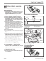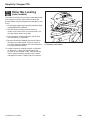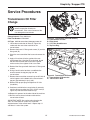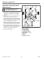
1
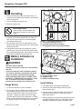
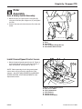
Dealer Setup
& Adjustment Instructions
Simplicity ZT3000 / Snapper 355Z
Zero-Turn Riders & Mowers
This Dealer Setup Instruction covers the following products:
TABLE OF CONTENTS:
Mfg. No.
SAFETY RULES .................................................................2
Description
SETUP PROCEDURES
Simplicity Models:
5900660 ZT3000B2444, Simplicity 24HP Briggs & Stratton ZT3000
Zero-Turn Rider with 44” Mower
5900662 ZT3000B2450, Simplicity 24HP Briggs & Stratton ZT3000
Zero-Turn Rider with 50” Mower
5900684 ZT3000B2450CE, Simplicity 24HP Briggs & Stratton
ZT3000 Zero-Turn Rider with 50” Mower (CE/Export)
Quick Setup List ................................................................3
Uncrating ............................................................................4
Battery Activation & Installation ......................................4
Rider Assembly .................................................................5
Seat and Safety Switch Assembly ...................................5
Install Ground Speed Control Levers ...............................5
Check Fluid levels .............................................................5
Fill and Check Engine Oil.................................................6
Check Transmission Oil Level .........................................6
Reduce and Check Tire Pressure ....................................6
Torque Mower Blades .......................................................7
Lubrication .........................................................................7
Perform Safety Checks .....................................................8
Functional Tests...............................................................8
Mower Blade Stopping Check..........................................8
Seat Switch Connection ...................................................8
Burnish PTO Clutch .........................................................8
Safety Interlock System ...................................................9
Snapper Models:
5900681 Snapper 355ZB2444
5900682 Snapper 355ZB2450
5900685 Snapper 355ZB2450CE
ATTENTION SETUP PERSONNEL:
The safety warnings provided in this guide and in
the operator's manual included with the unit contain
important information that must be obeyed when
assembling, setting-up, operating, servicing,
transporting, or storing the unit.
These warnings are highlighted by the safety alert triangle
symbol shown above, which signifies that an important safety
message is being provided.
You must read, understand, and follow these warnings and
instructions, and use safe shop and work practices at all
times while working on or around this unit and all other
outdoor power equipment.
ADJUSTMENT PROCEDURES
Seat Adjustments ............................................................10
Ground Speed Control Lever Adjustment.....................10
Operator Adjustment ......................................................10
Speed Balancing Adjustment .........................................11
Return-To-Neutral & Neutral Adjustment ......................11
Parking Brake Adjustment..............................................12
Suspension Adjustment .................................................13
PTO Clutch Adjustment ..................................................14
PTO Clutch Adjustment .................................................14
Blade Brake Check ........................................................14
Mower Deck Leveling ......................................................15
Roller Bar Leveling ..........................................................16
Sections and items denoted by the Setup symbol
provide the information necessary to fully assemble,
test, and prepare the units described above for
delivery to your customers.
Additional information concerning functional tests,
general adjustment procedures, and the location of
normal lubrication points are included in these
instructions.
SERVICE PROCEDURES
Transmission Oil Filter Change .....................................17
Hydraulic Pump Drive Belt Replacement ......................18
Mower Belt Replacement ................................................19
Form No. 5101067
Revision 01
Rev. Date: 8/2007
8/2007
1
TP 300-7337-01-CH-SMN
Simplicity / Snapper ZTR
SAFETY RULES
Read these safety rules and follow them closely. Failure to obey these rules could result in loss of control of equipment, severe
personal injury or death to you, yourself or bystanders, or damage to property or equipment. This mowing deck is capable of
amputating hands and feet and throwing objects. The triangle
in text signifies important cautions or warnings which must be
followed.
• Keep all movement on the slopes slow and gradual. Do not make
sudden changes in speed or direction.
• Avoid starting or stopping on a slope. If tires lose traction,
disengage the blade(s) and proceed slowly straight down the
slope.
DO NOT
• Do not turn on slopes unless necessary, and then, turn slowly and
gradually downhill, if possible.
• Do not mow near drop-offs, ditches, or embankments. The unit
could suddenly turn over if a wheel is over the edge of a cliff or
ditch, or if an edge caves in.
• Do not mow on wet grass. Reduced traction could cause sliding.
• Do not try to stabilize the unit by putting your foot on the ground.
• Do not use grass catcher on steep slopes.
III. Children
Tragic accidents can occur if the operator is not alert to the presence
of children. Children are often attracted to the unit and the mowing
activity. Never assume that children will remain where you last saw
them.
1. Keep children out of the mowing area and under the watchful care
of another responsible adult.
2. Be alert and turn unit off if children enter the area.
3. Before and when backing, look behind and down for small
children.
4. Never carry children. They may fall off and be seriously injured or
interfere with safe unit operation.
5. Never allow children to operate the unit.
6. Use extra care when approaching blind corners, shrubs, trees, or
other objects that may obscure vision.
IV. Service
1. Use extra care in handling gasoline and other fuels. They are
flammable and vapors are explosive.
a) Use only an approved container.
b) Never remove gas cap or add fuel with the engine running.
Allow engine to cool before refueling. Do not smoke.
c) Never refuel the unit indoors.
d) Never store the unit or fuel container inside where there is an
open flame, such as a water heater.
d) Clean up oil and fuel spills immediately.
2. Never run a unit inside a closed area.
3. Keep nuts and bolts, especially blade attachment bolts, tight and
keep equipment in good condition.
4. Never tamper with safety devices. Check their proper operation
regularly.
5. Keep equipment free of grass, leaves, or other debris build-up.
6. Stop and inspect the equipment if you strike an object. Repair, if
necessary, before restarting.
7. Never make adjustments or repairs with the engine running.
8. Grass catcher components are subject to wear, damage, and
deterioration, which could expose moving parts or allow objects to
be thrown. Frequently check components and replace, when
necessary, with manufacturer’s recommended parts.
9. Mower blades are sharp and can cut. Wrap the blade(s) or wear
gloves, and use extra caution when servicing them.
10. Check brake operation frequently. Adjust and service as required.
11. Allow the unit to cool before storing.
IMPORTANT – Safe operation practices for riding mowers.
I. General operation
1. Read, understand, and follow all instructions in the manual and on
the unit before starting.
2. Only allow responsible adults, who are familiar with the
instructions, to operate the unit.
3. Clear the area of objects such as rocks, toys, wire, etc., which
could be picked up and thrown by the blade(s).
4. Be sure the area is clear of other people before mowing. Stop the
unit if anyone enters the area.
5. Never carry passengers.
6. Do not mow in reverse unless absolutely necessary. Always look
down and behind before and while backing.
7. Be aware of the mower discharge direction and do not point it at
anyone. Do not operate the mower without either the entire grass
catcher or the guard in place.
8. Slow down before turning.
9. Never leave a running unit unattended. Always turn off blades, set
parking brake, stop engine, and remove keys before dismounting.
10. Turn off blades when not mowing.
11. Stop engine before removing grass catcher or unclogging chute.
12. Mow only in daylight or good artificial light.
13. Do not operate the unit while under the influence of alcohol or
drugs.
14. Watch for traffic when operating near or crossing roadways.
15. Use extra care when loading or unloading the unit into a trailer or
truck.
II. Slope operation
Slopes are a major factor related to loss-of-control and tip-over
accidents, which can result in severe injury or death. All slopes require
extra caution. If you cannot back up the slope or if you feel uneasy on
it, do not mow it.
WARNING – SLOPE OPERATION
Never operate on slopes greater than 15° which is a rise of 5.4 feet
(1,6 m) vertically in 20 feet (6 m) horizontally. Select slow ground
speed before driving onto slope. In addition to front and rear
weights, use extra caution when operating on slopes with rearmounted grass catcher. Mow UP and DOWN the slope, never
across the face, use caution when changing directions and DO
NOT START OR STOP ON SLOPE.
DO
• See your authorized dealer for recommendations of wheel weights
or counterweights to improve stability.
• Mow across slopes, not up and down.
• Remove obstacles such as rocks, tree limbs, etc.
• Watch for holes, ruts, or bumps. Uneven terrain could overturn the
unit. Tall grass can hide obstacles.
• Use slow ground speed so that you will not have to stop or change
speeds while on the slope.
• Use extra care with grass catchers or other attachments. These
can change the stability of the unit.
TP 300-7337-01-CH-SMN
2
8/2007
Simplicity / Snapper ZTR
Quick Setup List Page
Setup Procedure
Steps to Perform
4
Uncrating
❏ Remove crate & banding.
❏ Place transmissions in PUSH position & roll off skid.
4
Battery Activation &
Installation
❏ Charge the battery
❏ Test battery with hydrometer or load-tester.
❏ Install & secure battery.
5
Rider Assembly
❏ Install the seat and connect the seat switch
❏ Install ground speed control levers.
6
Check Fluid Levels
❏ Fill & check Engine oil level.
❏ Check transmission fluid level.
❏ Reduce & check tire pressures
(Front tires 40 psi, rear tires 15 psi).
7
Mower Assembly
❏ Torque mower blade bolts.
7
Lubrication
❏ Lubricate all grease & oil points.
8
SAFETY CHECKS
❏
❏
❏
❏
Check for LOOSE HARDWARE.
Check all OPERATOR CONTROLS.
Test PARKING BRAKE.
Perform MOWER BLADE STOPPING CHECK.
(Blade must stop within 5 seconds!)
❏ Perform SAFETY INTERLOCK SYSTEM CHECK.
8
Burnish Electric Clutch
❏ Burnish electric clutch (run for 15 seconds, repeat 10 times).
❏ Repeat MOWER BLADE STOPPING CHECK.
(Blade must stop within 5 seconds!)
8/2007
3
TP 300-7337-01-CH-SMN
Simplicity / Snapper ZTR
Uncrating
1. Using a reciprocating utility saw or equivalent, cut
crate away from bottom skid. Remove crate. Remove
shrink-wrap plastic.
A
2. Cut any banding securing the unit.
3. Release parking brake.
B
IMPORTANT NOTE
When cutting crate from bottom skid,
use caution around tires and mower
rollers.
C
4. Pull both transmission release levers (A, Figure 1)
back and out so that they lock in the disengaged
(free-wheel) position (C).
Figure 1. Transmission Release Levers
A. Transmission Release Levers
B. Engaged Position (Drive Position)
C. Disengaged Position (Free-wheel Position)
5. Be sure there are no nails or sharp objects on the
bottom of the skid to puncture the tires. Roll the rider
forward off the skid.
6. Engage the transmissions by pulling the hydraulic
release levers rearward and inward to release them
from the disengaged position and allow them to move
forward to the engaged (drive) position (B).
Battery Activation &
Installation
WARNING
A
BATTERY SAFETY RULES
• Battery acid causes severe burns. Avoid contact
with skin.
• Wear eye protection while handling the battery.
• To avoid an explosion, keep flames and sparks
away from battery, especially while charging.
• When installing battery cables, CONNECT THE
POSITIVE (+) CABLE FIRST and negative (-) cable
last. If not done in this order, the positive
terminal can be shorted to the frame by a tool.
C
Figure 2. Battery
A. Positive Cable & Cover
B. Negative Cable
C. Rubber Hold-Down Strap
Install Battery
Charge Battery
1. Install the battery in the battery compartment
1. Tip the seat forward to access the battery.
2. Connect the red positive battery cable (A) to the
positive battery post.
2. To charge the battery, follow the instructions provided
by the battery charger manufacturer as well as all
warnings included in the safety rules section of this
document. Charge the battery until fully charged
(until the specific gravity of the electrolyte is 1.250 or
higher and the electrolyte temperature is at least 60°
F). Do not charge at a rate higher than 10 amps.
TP 300-7337-01-CH-SMN
B
3. Connect the black negative battery cable (B) to the
negative battery post using a capscrew, washer,
lockwasher and nut.
4. Secure the battery into the battery compartment using
the rubber hold down strap (C). The battery cables
should be underneath the rubber hold-down strap.
4
8/2007
Simplicity / Snapper ZTR
Rider
Assembly
B
A
C
Seat & Safety Switch Assembly
1. Mount the seat (A, Figure 3) to the seat plate (B)
using four 5/16-18 nylock flange nuts (C) and tighten
securely.
2. Connect the seat switch wire harness (D) to the seat
switch.
D
C
Figure 3. Seat Installation
A. Seat
B. Seat Plate
C. 5/16-18 Nylock Flange Nut (4)
D. Seat Switch Wire Harness
Install Ground Speed Control Levers
1. Mount the ground speed control levers (D, Figure 4)
to the control lever base (E) using four 5/16-18 x 1”
bolts, lockwashers, and washers (A, B & C).
A B C
NOTE: Before operating the unit the ground speed
control levers and seat must be adjusted to fit the
operator. See SEAT ADJUSTMENTS and GROUND
SPEED CONTROL LEVER ADJUSTMENTS in the
Adjustments section.
E
D
Figure 4. Install Control Levers
A. 5/16-18 x 1” Bolts
B. 5/16 Lockwashers
C. 5/16 Washers
D. Control Lever
E. Control Lever Base
8/2007
5
TP 300-7337-01-CH-SMN
Simplicity / Snapper ZTR
Check
Fluid Levels
B
Fill & Check Engine Oil
A
1. Use the dipstick (C, Figure 5) to check the engine oil
level. If necessary add engine oil. Check engine
manufacturer’s owner’s manual for oil
recommendations.
Check /Fill Transmission Oil
Oil Type: 20W-50 conventional detergent motor oil.
1. Check the oil level when the unit is cold. Raise the
seat plate to gain access to the transmission oil
reservoirs (A, Figure 6). The oil should be up to the
“FULL COLD” mark. If the oil is below this level,
proceed to step 2.
C
Figure 5. Check Fluid Levels
A. Fuel Tank Cap
B. Transmission Oil Caps
C. Engine Oil Dip Stick
2. Before removing the reservoir cap, make sure the
area around the reservoir cap and fill neck of the
reservoir is free of dust, dirt, or other debris. Remove
the transmission oil caps (B, Figure 5).
3. Add oil up to the “FULL COLD” mark (B, Figure 6).
4. Reinstall the reservoir cap.
A
B
Figure 6. Transmission Oil Fill Level
A. Transmission Oil Reservoirs
B. “FULL COLD” Mark
Reduce & Check Tire
Pressures
The tires are over-inflated for shipping purposes. Inflate
to the pressures shown. Note that these pressures may
differ slightly from the “Max Inflation” stamped on the
side-wall of the tires. The pressures shown provide
proper traction, improve cut quality, and extend tire life.
Tire
Front
Pressure
40 psi (2,76 bar)
Rear
15 psi (1,03 bar)
Figure 7. Tire Pressures
TP 300-7337-01-CH-SMN
6
8/2007
Simplicity / Snapper ZTR
Torque Mower Blades
WARNING
B
For your personal safety, blade mounting
capscrews must each be installed with a hex
washer and spring washer, then securely
tightened. Torque blade mounting capscrew to
45 - 55 ft. lbs. (61 - 75 N.m.)
A
D
1. Check that blades are installed with the tabs pointing
up toward deck as shown in Figure 8. Secure with a
capscrew, spring washer and spline/hex washer (be
certain the spline/hex washer is aligned with the
shaft). Use a wooden block to prevent blade rotation
and torque capscrews to 45-55 ft.lbs. (61-75 N.m.).
Figure 8. Mower Blade Installation
A. Mower Blade Mounting Bolt
B. Hex Washer
C. Mower Blade Air Lift (Install With Points Up)
D. 4 X 4 Wooden Block
E. Spring Washer
Lubrication
Lubricate the unit at the following lubrication points
shown in Figure 9.
Grease:
Oil:
• front caster wheel axles
• front caster yokes
• mower deck idler arm
• mower deck arbors
• control handle pivots
• discharge chute hinge
Generally, all moving metal parts should be oiled where
contact is made with other parts. Keep oil and grease off
belts and pulleys. Remember to wipe fittings and
surfaces clean both before and after lubrication.
Use grease fittings when present. Disassemble parts to
apply grease to moving parts when grease fittings are
not installed. Not all greases are compatible. Use
automotive-type lithium grease.
Lube Idler
Arm Pivot
Figure 9. Lubrication
8/2007
7
TP 300-7337-01-CH-SMN
Simplicity / Snapper ZTR
Perform
Safety Checks
Burnish PTO Clutch
1. Select a safe area to operate the mower deck. With
the ground speed control levers in the neutral
position, the parking brake engaged, the PTO switch
disengaged, and an operator in the seat, start the
tractor engine. Run the engine at full throttle.
WARNING
Disengage the PTO, stop the engine, set the
parking brake, and wait for moving parts to stop
before leaving operator's position for any reason.
2. Engage the PTO switch and run the deck for fifteen
seconds. Disengage the PTO switch and wait for the
mower drive belt to stop.
If the unit does not pass the test, do not operate
it. Under no circumstance should you attempt to
defeat the purpose of the safety system.
3. Repeat step 2 above ten times, and then re-check the
mower blade stopping time. (Stopping time must be
five seconds or less.)
Functional Tests
1. Check for loose bolts, screws, nuts, etc.
2. Start the engine and check all controls for proper
operation: ground speed control levers, parking brake
lever, throttle and choke cables, electric PTO clutch,
attachment lift, etc.
3. Stop the engine and check for fluid leaks: oil,
gasoline, or transmission oil.
4. If any control fails to operate properly during testing or
seems to be out of adjustment, check and readjust it
according to the following Adjustments section.
4. Turn the key to OFF to end testing.
Mower Blade Stopping Check
Mower blades and mower drive belt should come to a
complete stop within five seconds after the electric clutch
switch is turned off.
With the ground speed control levers in the neutral
position, the parking brake engaged, the PTO clutch
switch disengaged, and an operator in the seat, start the
tractor engine. Run the engine at full throttle. Engage the
PTO clutch switch and wait several seconds. Disengage
the PTO clutch switch and check the time it takes for the
mower drive belt to stop. If the mower drive belt does not
stop within five seconds, adjust the PTO clutch according
to the instructions in the PTO Clutch Adjustment section.
Seat Switch Connection
Check that the seat switch wire harness (D, Figure 2) is
connected to the seat switch.
TP 300-7337-01-CH-SMN
8
8/2007
Simplicity / Snapper ZTR
EXPORT MODELS ONLY:
NORTH AMERICAN
MODELS:
SAFETY INTERLOCK
SYSTEM
SAFETY INTERLOCK
SYSTEM
This unit is equipped with safety interlock switches.
These safety systems are present for your safety, do not
attempt to bypass safety switches, and never tamper
with safety devices. Check their operation regularly.
This unit is equipped with safety interlock switches.
These safety systems are present for your safety, do
not attempt to bypass safety switches, and never
tamper with safety devices. Check their operation
regularly.
Operational SAFETY Checks
Operational SAFETY Checks
Test 1 — Engine should NOT crank if:
Test 1 — Engine should NOT crank if:
• PTO switch is engaged, OR
• Parking brake is not engaged, OR
• Ground speed control levers are not in the
NEUTRAL position.
• PTO switch is engaged, OR
• Parking brake is not engaged, OR
• Ground speed control levers are not in their
NEUTRAL positions.
Test 2 — Engine SHOULD crank and start if:
Test 2 — Engine SHOULD crank if:
• PTO switch is NOT engaged, AND
• Parking brake is engaged, AND
• Ground speed control levers are locked in the
NEUTRAL position, AND
• Operator is in seat.
• PTO switch is NOT engaged, AND
• Parking brake is engaged, AND
• Ground speed control levers are locked in their
NEUTRAL positions.
Test 3 — Engine should SHUT OFF if:
Test 3 — Engine should SHUT OFF if:
• Operator rises off seat with PTO engaged, OR
• Operator rises off seat under any condition.
• Operator moves the ground speed control levers out
of their neutral positions before disengaging parking
brake.
• Operator rises off seat with parking brake
disengaged, OR
• Operator moves the ground speed control levers
out of their neutral positions before disengaging
parking brake.
Test 4 — Blade Brake Check
The mower blades and the mower drive belt should
come to a complete stop within five (5) seconds after the
PTO switch is turned off (or operator rises off seat). If
the mower drive belt does not stop within five (5)
seconds, see your dealer.
Test 4 — Blade Brake Check
The mower blades and the mower drive belt should
come to a complete stop within five seconds after the
PTO switch is turned off (or operator rises off seat). If
the mower drive belt does not stop within five seconds,
see your dealer.
NOTE: Once the engine has stopped, PTO switch must
be turned off, parking brake must be engaged, and the
ground speed control handles must be locked in the
NEUTRAL position after the operator returns to the seat
in order to start the engine.
NOTE: Once the engine has stopped, the PTO switch
must be turned off, parking brake must be engaged,
and the ground speed control handles must be locked
in their NEUTRAL positions after the operator returns
to the seat in order to start the engine.
WARNING
WARNING
If the unit does not pass a safety test, do not
operate it. See your authorized dealer. Under no
circumstance should you attempt to defeat the
purpose of the safety interlock system.
If the unit does not pass a safety test, do not
operate it. Under no circumstance should you
attempt to defeat the purpose of the safety
interlock system.
8/2007
9
TP 300-7337-01-CH-SMN
Simplicity / Snapper ZTR
Adjustment
Procedures
Seat Adjustments
The seat and ground speed control levers should be
adjusted so that operator’s elbows are supported by the
arm rests when his/her hands are on the controls, and
the ground speed control levers can be moved through
their full range of motion without contacting the operator’s
legs.
Seat Position Adjustment
The seat can be adjusted forward and back. Move the
adjustment lever (A, Figure 10) towards the left hand side
of the machine, slide the seat to the desired position, and
release the adjustment lever.
A
Figure 10. Seat Adjustment
A. Adjustment Lever
Ground Speed Control
Lever Adjustment
A
Operator Adjustment
The control levers can be adjusted in three ways. The
alignment of the control levers, the placement of the
levers (how close the ends are to one another) and the
height of the levers can be adjusted.
B
To Adjust the Handle Alignment: Loosen the mounting
bolts (A, Figure 11) and pivot the ground speed control
lever(s) (C) to align with each other. When desired
position is achieved tighten the mounting bolts.
To Adjust the Handle Placement: Loosen the jam nuts
and adjust the placement bolt (B, Figure 11) in or out to
properly adjust the lever end spacing. When desired
position is achieved tighten the jam nuts.
To Adjust the Handle Height: Remove the mounting
hardware (A, Figure 11) and reposition the handle either
up or down from its original position. You will need to
readjust the handle alignment as described above.
TP 300-7337-01-CH-SMN
C
Figure 11. Control Lever Adjustment
A. Alignment Hardware
B. Placement Hardware
C. Ground Speed Control Lever
10
8/2007
Simplicity / Snapper ZTR
Speed Balancing Adjustment
C
If the rider veers to the right or left when both the ground
speed control levers are in the maximum forward or
reverse position, the top speed of each of these levers
can be balanced by turning the adjustment bolt(s) (A & C,
Figure 12). Only adjust the speed of the wheel that is
traveling faster.
A
TO REDUCE THE SPEED OF THE FASTER WHEEL
1. Loosen the securing nut.
B
2. Turn the top speed adjustment bolt (A & C, Figure 12)
COUNTER-CLOCKWISE to reduce the speed.
Figure 12. Top Speed Adjustment
A. Forward Top Speed Adjustment Bolt
B. Control Lever Base
C. Reverse Top Speed Adjustment Bolt
3. Retighten the securing nut when adjustment is
complete.
WARNING
DO NOT adjust the rider for a faster overall speed
forward or reverse than it was designed for.
Return-To-Neutral &
Neutral Adjustment
RETURN-TO-NEUTRAL ADJUSTMENT
A
To determine if it is necessary to adjust the neutral
return, perform the following steps.
1. Disengage the PTO, engage the parking brake and
turn off the engine.
2. Move the ground speed control levers into the
operating position, pull levers rearward and release.
3. Move the ground speed control levers out towards
the neutral position. If the levers do not align with the
notches in the neutral lock plate, it is necessary to
adjust the neutral return rod (C, Figure 13).
B
C
TO ADJUST:
1. Loosen the jam nut (B) locked against the clevis (A).
2. Turn the neutral return rod (C) to adjust handle
position.
4. Pull lever rearward and release to check position
again. Adjust as necessary to align levers with
notches.
It is important to note that after every adjustment of the
neutral return rod, the lever must be pulled rearward and
released to properly check the neutral position.
Figure 13. Return-To-Neutral Adjustment
A. Clevis
B. Jam Nut
C. Neutral Return Rod
5. Once the lever alignment has been adjusted, lock
jam nut against the clevis.
NEUTRAL ADJUSTMENT
The neutral adjustment for this unit is preset at the
factory.
8/2007
11
TP 300-7337-01-CH-SMN
Simplicity / Snapper ZTR
Parking Brake
Adjustment
C
B
E
1. Disengage the PTO, stop the engine, engage the
parking brake, and remove the key from the ignition.
A
2. Raise the seat plate to gain access to the parking
brake components.
G
3. Measure the distance from the top of the brake spring
rod (C, Figure 14) to the top of the lock nut (D) on
both sides of the unit. The measurement should be
.50” (1,27 cm). If not, adjust the locknut to achieve
the measurement of .50” (1,27 cm).
4. Measure the distance between the bottom of the
brake shaft weldment (G) and the top of the set collar
(F). The measurement should be .375” (0,95 cm). If
not, position the set collar until the measurement
equals .375” (0,95 cm).
TP 300-7337-01-CH-SMN
D
F
Figure 14. Parking Brake Adjustment
A. Brake Spring
B. First Measurement - .50” (1,27 cm)
C. Brake Spring Rod
D. Lock Nut
E. Second Measurement - .375” (0.95 cm)
F. Set Collar
G. Brake Shaft Weldment
12
8/2007
Simplicity / Snapper ZTR
Suspension Adjustment
(select models)
A
The shock assembly can be adjusted to vary the amount
of pre-load applied to the springs. This allows the
operator to customize the ride according to operator’s
weight and operating conditions.
LESS PRE-LOAD:
• Light operator weight
• Softer, more cushioned ride
• Best for relatively flat terrain
MORE PRE-LOAD:
Figure 15. Suspension Adjustment
A. Front Shock Adjustment Collar
• Heavy operator weight
• Stiffer, more rigid ride
• Better handling and greater stability on hilly terrain
TO ADJUST THE SPRING PRE-LOAD:
1. Park machine on a flat, level surface. Disengage the
PTO, stop the engine and engage the parking brake.
2. See Figure 15. Turn the pre-load adjustment collar
(A) CLOCKWISE to increase the pre-load, turn
COUNTER-CLOCKWISE to decrease the pre-load.
Make sure both front shocks are set to the same
amount of pre-load. Make sure both rear shocks are
set to the same amount of pre-load.
NOTE: After adjusting the front shock assembly, move
the ring against the adjustment collar to prevent the
collar from loosening during operation.
8/2007
13
TP 300-7337-01-CH-SMN
Simplicity / Snapper ZTR
A
B
B
B
C
B
A
Figure 17. Adjust PTO Clutch
A. Window
B. Adjustment Nut
C. .016”-.018” (0,40-0,45mm) Feeler Gauge
Figure 16. PTO Clutch Adjustment
A. Adjustment Window (Qty. 3, one shown)
B. Adjustment Nut
PTO Clutch Adjustment
WARNING
To avoid serious injury, perform adjustments only
with engine stopped, key removed and rider on
level ground.
Check the PTO clutch adjustment after every 100 hours
of operation. Also perform the following procedure if the
clutch is slipping or will not engage, or if a new clutch
has been installed.
1. Remove key from ignition switch and disconnect
spark plug wires to prevent the possibility of
accidental starting while the PTO is being adjusted.
2. See Figure 16. Note the position of the 3 adjustment
windows (A) in the side of the brake plate and the
nylock adjustment nuts (B).
Blade Brake Check
Mower blades and mower drive belt should come to a
complete stop within five seconds after electric PTO
switch is turned off.
1. With parking brake engaged, PTO disengaged and
an operator in the seat, start the engine.
3. Insert a .016”-.018” (0,40-0,45mm) feeler gauge (C)
through each window, positioning the gauge between
the rotor face and the armature face as shown in
Figure 17.
2. Have an assistant observe the mower drive belt
through the opening between the frame and top of
mower deck. Engage the PTO and wait several
seconds. Disengage the PTO and check the amount
of time it takes for the mower drive belt to stop.
4. Alternately tighten the adjustment nuts (B, Figure 16)
until the rotor face and armature face just contacts
the gauge.
3. If the mower drive belt does not stop within five
seconds, perform the PTO Clutch Adjustment. If the
belt still does not stop within 5 seconds, replace the
clutch.
5. Check the windows for an equal amount of tension
when the gauge is inserted and removed, and make
any necessary adjustments by tightening or
loosening the adjustment nuts.
NOTE: The actual air gap between the rotor and
armature may vary even after performing the adjustment
procedure. This is due to dimensional variations on
component parts, and is an acceptable condition.
6. Check the mower blade stopping time. The mower
blades and mower drive belt should come to a
complete stop within five seconds after the electric
PTO switch is turned off.
TP 300-7337-01-CH-SMN
14
8/2007
Simplicity / Snapper ZTR
Mower Deck Leveling
Perform these adjustments on a flat level surface.
SIDE-TO-SIDE LEVELING
1. With the mower installed, park the machine on a flat,
lever surface such as a concrete floor. Engage the
parking brake, disengage the PTO, turn of the
engine, and remove the key from the ignition. Turn
the front wheels so they are straight.
Figure 18. Orient Blades Side-to-Side
2. Check for bent blades and replace if necessary.
A
3. Place the mower cutting height pin in the 4th hole
from the bottom (see insert, Figure 20). Arrange the
outside mower blades so that they are pointing from
side-to-side (Figure 18).
B
C
4. Measure the distance between the outside tips of
each blade and the ground (Figures 18 & 19). If there
is more than 1/8” (3mm) difference between the
measurements on each side, proceed to step 5. If the
difference is 1/8” (3mm) or less, proceed to step 6.
Figure 19. Measure Blade Tips to Ground
A. Mower Deck
C. Level Ground
B. Blade Tip
5. Use the rear leveling links (B, Figure 20) to adjust the
side-to-side leveling of the deck. Repeat step 4 if
necessary.
FRONT-TO-BACK LEVELING
6. Arrange the blades so they face front-to-back (Figure
21).
B
C
7. Measure the distance from the ground to the front tip
of the center blade, and from the ground to rear tips
of left-hand and right-hand blades (Figures 19 & 21).
The front tip of the center blade should be 1/4" (6mm)
higher than rear tips of left-hand and right-hand
blades. If not, proceed with steps 8 - 11.
A
D
8. Check the length of the hanger rods. The rear
hanger rods (D, Figure 20) should be 15” (38,1 cm)
and is not adjusted. To adjust the pitch of the mower
deck, adjust the front leveling nuts only.
E
Figure 20. Mower Leveling
A. Front Leveling Nuts
B. Rear Leveling Rods
C. 4th Cutting Height Hole
D. Rear Hanger Rods
E. Front Lock Nuts
9. Loosen the front lock nuts (E, Figure 20).
10. Turn the leveling nuts (A, Figure 20) counterclockwise to lower the front of mower deck. Turn the
nuts clockwise to raise the front of the mower. Make
adjustments in small increments, trying to keep
tension on both leveling nuts.
11. Tighten the front lock nuts (E).
12. Re-check the blade measurement then repeat steps
7-11 as necessary.
Figure 21. Orient Blades Front-to-Back
8/2007
15
TP 300-7337-01-CH-SMN
Simplicity / Snapper ZTR
Roller Bar Leveling
(select models)
The rollers on this Zero Turn unit are not intended to ride
on the ground. DO NOT adjust rollers to ride on the
ground. Rollers riding on the ground will damage turf and
or unit.
A
1. First level the mower deck using the procedure found
in MOWER DECK LEVELING.
2. With the mower installed, place the rider on a
smooth, level surface such as a concrete floor. Turn
the front wheels so they are straight.
3. Place the mower cutting height pin in the 4th hole
from the bottom (C, Figure 20).
4. Measure the distance between the outside ends of
the roller bar and the ground. If there is more than
1/8” (3mm) difference between the measurements on
each side, proceed to step 5.
Figure 22. Roller Bar Leveling
A. Eccentric and Locknut
5. Locate the roller bar leveling eccentric and locknuts
(A, Figure 22). Loosen the locknut and turn the
eccentric to raise or lower a side. When the correct
level is achieved, hold the eccentric with a wrench
and tighten the locknut. Repeat step 4 if necessary.
TP 300-7337-01-CH-SMN
16
8/2007
Simplicity / Snapper ZTR
Service Procedures
Transmission Oil Filter
Change
A
B
Do not allow dirt, water, or other debris to
enter the expansion chamber or
transmission. Even a small amount of dirt
can damage the transmission
D
C
Change Interval: Every 200 Hours
Figure 23. Transmission (Left Side Shown.)
A. Transmission Oil Filter
B. Filter Guard
C. 1/4” Filter Guard Screws
D. Top Port Plug
Filter Part Number: 5101026X1
Oil Type: 20W-50 conventional detergent motor oil.
1. Locate the transmission oil filters (A, Figure 23)
underneath the rear of the machine on the
transmissions.
2. Remove the three 1/4” filter guard screws (C) and the
filter guard (B).
A
3. Clean the area around the filter base and remove the
filter.
4. Apply a film of new oil to the gasket of the new
replacement filter. After the oil has drained, thread
the new filter onto the filter base until the gasket
makes contact, then tighten 3/4 of a turn more.
5. Reinstall the filter guard with the three 1/4” filter guard
screws
B
6. Using a hex bit swivel socket or a modified allen
wrench remove the top port plug from the
transmissions.
Figure 24. Transmission Oil Reservoirs
A. Transmission Oil Reservoirs
B. “FULL COLD” Mark
7. Remove the transmission reservoir cap and fill with oil
until oil appears at the bottom of the transmission’s
top port (approximately 2 qts (1,89L).
8. Reinstall the top port plug and tighten to 15 ft lbs
(20,38 Nm).
9. Continue to add oil to the transmission oil reservoirs
until the oil lever reaches the “FULL COLD” mark (B,
Figure 24). Reinstall the oil reservoir cap.
10. Repeat this process for the other side of the machine.
11. Run the unit for several minutes and check the
transmission oil level.
IMPORTANT NOTE: Use caution after changing the
filter; air in the hydraulic system may affect the
responsiveness of the control levers. Repeat step 11
until the air is out of the system.
8/2007
17
TP 300-7337-01-CH-SMN
Simplicity / Snapper ZTR
Hydraulic Pump Drive Belt
Replacement
B
A
To avoid damaging belts, DO NOT
PRY BELTS OVER PULLEYS.
D
1. Park the rider on a smooth, level surface such as a
concrete floor. Disengage the PTO, engage the
parking brake, turn off the engine, and remove the
ignition key.
E
F
2. Remove the PTO drive belt (see MOWER BELT
REPLACEMENT for removal instructions).
3. Loosen the nut towards the front of the machine on
the spring anchor hook (H, Figure 25) to release the
majority of the belt tension. Use caution and remove
the nut to completely release the tension.
C
C
G
H
4. Remove the old belt and replace it with the new one.
Make sure the V-side of the belt runs in the grooves
of the crankshaft pulley and pump pulleys (B & C).
5. Reinstall the anchor hook (H) into the anchor tab and
loosely fasten the nut. Adjust the spring until a
measurement of 9” (22,86 cm) is achieved from the
outside of the spring hooks. Tighten nut.
6. Reinstall the PTO drive belt.
TP 300-7337-01-CH-SMN
Figure 25. Hydraulic Pump Drive Belt Replacement
(Shown from Below)
A. Pump Drive Belt
B. Crankshaft Pulley
C. Transmission Pulley
D. Idler Pulleys (stationary)
E. Idler Pulley
F. Idler Arm
G. Spring
H. Spring Anchor Hook
18
8/2007
Simplicity / Snapper ZTR
Mower Belt Replacement
To avoid damaging belts, DO NOT
PRY BELTS OVER PULLEYS.
A
C
1. Park the rider on a smooth, level surface such as a
concrete floor. Disengage the PTO, engage the
parking brake, turn off the engine, and remove the
ignition key.
B
A
A
D
2. Raise the mower deck to transport position. Pull the
belt tension lever (A, Figure 27) towards the rear of
the machine to release tension on the mower belt.
Secure the lever in the guard notch (B).
Figure 26. Mower Belt Routing
A. Arbor Pulleys
B. Back-Side Idler Pulleys
C. PTO Pulley
D. Belt Tension Release Lever
3. Remove the old drive belt and install the new one as
shown in Figure 26. Note that the back of the drive
belt must ride against the back-side idler pulleys (B).
Use the belt tension lever (A, Figure 26) to release
tension on the idler pulley for installation.
B
A
Figure 27. Release Belt Tension
A. Belt Tension Lever
B. Guard Notch
8/2007
19
TP 300-7337-01-CH-SMN
MANUFACTURING, INC.
500 N Spring Street / PO Box 997
Port Washington, WI 53074-0997
PRODUCTS, INC.
535 Macon Street
McDonough, GA., 30253
www.simplicitymfg.com
www.snapper.com
The Simplicity logo is a trademark of Briggs & Stratton
Corporation, Milwaukee, WI, USA.
The Snapper logo is a trademark of Briggs & Stratton
Corporation, Milwaukee, WI, USA
Briggs & Stratton Yard Power Products Group
Copyright © 2007 Briggs & Stratton Corporation
Milwaukee, WI, USA. All rights reserved.