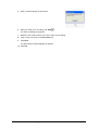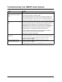
1
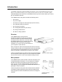
Installation and User's Guide
SMART Audio System 240
Product Registration
If you register your SMART product, we'll notify you of new features and
software upgrades.
Register online at www.smarttech.com/registration.
Keep the following information available, in case you need to contact
Technical Support:
Serial Number
Date of Purchase
FCC Warning
This device complies with Part 15 of the FCC Rules. Operation is subject to the following two conditions: (1) this device may not cause
harmful interference, and (2) this device must accept any interference received, including interference that may cause undesired
operation.
This equipment has been tested and found to comply with the limits for a Class B digital device, pursuant to Part 15 of FCC Rules.
These limits are designed to provide reasonable protection against harmful interference in a residential installation.
This equipment generates, uses and can radiate radio frequency energy and, if not installed and used in accordance with the
instructions, may cause harmful interference to radio communications. However, there is no guarantee that interference will not occur
in a particular installation.
You can determine whether the equipment is causing interference by disconnecting it from your computer. If the interference stops, it
was probably caused by the equipment.
Trademark Notice
SMART Audio, smarttech and the SMART logo are trademarks or registered trademarks of SMART Technologies ULC
in the U.S. and/or other countries. All other third-party product and company names may be the trademarks of their
respective owners.
Copyright Notice
© 2008–2009 SMART Technologies ULC. All rights reserved. No part of this publication may be reproduced, transmitted, transcribed, stored in a retrieval
system or translated into any language in any form by any means without the prior written consent of SMART Technologies ULC. Information in this
manual is subject to change without notice and does not represent a commitment on the part
of SMART.
Patent Nos. US6320597; and US6326954. Other patents pending.
Printed in Japan 04/2009
Important Information
Read this installation and user’s guide carefully before installing and using your SMART Audio
240 system. This guide describes the proper installation and operational procedures that will
keep you safe from harm and prevent damage to the system.
Safety Warnings
WARNING
• Failure to follow the installation instructions shipped with your SMART Audio
240 system or adhere to the following procedures could result in personal
injury and/or damage to the product.
• Ensure that you bundle and mark cables extending across the floor to your
SMART Audio 240 system to avoid a trip hazard.
• To reduce the risk of fire or electric shock, do not expose the SMART Audio
240 system to rain or moisture.
• Do not open or disassemble the SMART Audio 240 system. Opening the
casing voids your warranty.
• Do not turn on the receiver until all the speaker cables are connected to the
speakers.
• You must secure each ceiling speaker using a safety strap or cable that
conforms to your local safety codes.
• Only recharge the batteries included with your SMART Audio 240 system.
Other Precautions
Do not expose the SMART Audio 240 system to excessive levels of dust, humidity or smoke.
To reduce the chance of the microphone batteries leaking:
•
Only recharge the batteries included with the SMART Audio 240 system. Do not recharge
alkaline batteries.
•
Use only AA batteries.
•
Do not mix new and used batteries.
•
Orient the batteries’ positive and negative terminals so that they match the positive and
negative markings in the battery compartment.
•
Do not store batteries in the microphones for an extended period of time.
•
Do not heat, disassemble or short the batteries, or expose the batteries to fire or high
temperatures.
•
If the batteries do leak, avoid eye and skin contact with the batteries and the leaked
material.
•
Dispose of exhausted batteries and product components in accordance with the
regulations for where you live.
99-00855-20 C0
Important Information
i
ii
Important Information
99-00855-20 C0
Table of Contents
Important Information
i
Safety Warnings ...................................................................................................................i
Other Precautions ................................................................................................................i
Introduction
1
Receiver ............................................................................................................................. 1
Microphones....................................................................................................................... 2
Microphone Chargers......................................................................................................... 2
Infrared Sensors................................................................................................................. 2
Speakers ............................................................................................................................ 3
Installing Your SMART Audio 240 System
5
Chapter Contents ............................................................................................................... 5
Additional Items You Need ................................................................................................. 5
Determining the Best Location for Your SMART Audio 240 System.................................. 6
The Receiver ............................................................................................................... 6
The Speakers .............................................................................................................. 6
The Infrared Sensors................................................................................................... 7
Installing the Receiver........................................................................................................ 8
Installing the Ceiling Infrared Sensor ................................................................................. 9
Installing the Ceiling Speakers ......................................................................................... 10
Installing the Wall Speakers ............................................................................................. 12
Using Your SMART Audio 240 System
13
Using the Receiver........................................................................................................... 13
Using the Microphones .................................................................................................... 13
Using External Audio Devices.......................................................................................... 15
Recording Audio with SMART Notebook Software .......................................................... 15
Troubleshooting Your SMART Audio System
17
Regulatory Compliance
19
Waste Electrical and Electronic Equipment Regulations ................................................. 19
Restriction of Certain Hazardous Substances (RoHS) Directives.................................... 19
Customer Support
21
Online Support ................................................................................................................. 21
Training ............................................................................................................................ 21
Contacting SMART Technical Support............................................................................. 21
General Inquiries.............................................................................................................. 21
Warranty........................................................................................................................... 22
Registration ...................................................................................................................... 22
99-00855-20 C0
Table of Contents
iii
iv
99-00855-20 C0
Introduction
The SMART Audio 240 system amplifies the teacher’s voice so that students who sit in the
back of your classroom hear you as clearly as those who sit in the front. The audio system
makes speaking to the class more comfortable because you don’t need to strain your voice to
get your students’ attention.
Your SMART Audio 240 system includes the following items:
•
one receiver
•
one power supply
•
one teacher microphone with lanyard (lanyard not shown)
•
one handheld student microphone
•
two microphone chargers
•
four rechargeable batteries (not shown)
•
one ceiling infrared sensor
•
four wall or ceiling speakers
Receiver
Your SMART Audio receiver has two
microphone channels so that you can use the
teacher microphone and the handheld student
microphone at the same time. It has two audio
line inputs that allow you to connect an external
audio device like a CD player, DVD player,
computer, TV or VCR. You can record audio on
your computer or other devices.
Each microphone channel and external audio device line has a
volume control so that you can blend softer and louder speaking
voices with audio from external devices. You can change the
audio tonal quality by adjusting the tone dial on the receiver.
There’s an infrared sensor on the front of the receiver that detects
the microphones’ infrared signal. You can use either the infrared
sensor on the receiver or up to three external ceiling sensors.
Receiver’s Power Supply
Microphones
Your SMART Audio system includes a teacher microphone and
a handheld student microphone. You can attach the included
lanyard to the teacher microphone and wear it around your
neck. You can use the handheld student microphone when
team teaching, or you can pass it to students and allow them to
participate in lesson activities.
These microphones have power and channel selector switches.
The battery indicator light glows green when the batteries are
fresh and glows red when the batteries need to be recharged or
replaced.
99-00855-20 C0
Introduction
Teacher
Microphone
Handheld Student
Microphone
1
There are transmitters on the microphones that transmit an infrared signal. To ensure optimal
performance, don’t cover or block the infrared transmitters. There must be a clear line of sight
between the microphones and the infrared sensor in order for the audio system to work
properly.
Microphone Chargers
If you use the included rechargeable batteries, you can
recharge the microphones by connecting a microphone charger
when the battery indicator light changes from green to red.
Fully charged batteries last approximately eight hours in the
teacher microphone. For the handheld student microphone,
fully charged batteries last approximately six hours when you
set it to High and approximately nine and a half hours when you
set it to Low. It takes approximately eight hours to fully recharge
the batteries.
Infrared Sensors
Infrared sensors detect microphone signals and send them to
the receiver. You can use either the infrared sensor on the
front of the receiver or the infrared sensor for the ceiling.
Ensure that there is a clear line of sight between the infrared
sensor and the infrared transmitter on the microphones.
Speakers
Your SMART Audio system comes with four wall or ceiling
speakers. The speakers mute if the signal from the
microphones is blocked or weak. This prevents unwanted
static and noise from occurring.
Ceiling Speaker
Wall Speaker
2
Introduction
99-00855-20 C0
Installing Your SMART Audio 240 System
This chapter helps you plan your installation and describes the installation process for your
SMART Audio 240 system.
Chapter Contents
•
Additional Items You Need (page 5)
•
Determining the Best Location for Your SMART Audio System (page 6)
•
Installing the Receiver (page 8)
•
Installing the Ceiling Infrared Sensor (page 9)
•
Installing the Ceiling Speakers (page 10)
•
Installing the Wall Speakers (page 12)
Additional Items You Need
You need to purchase the following materials from your local building supply store.
•
•
For the speakers, you need the following:
–
Plenum rated speaker cable
–
The appropriate screws for your wall. For example, purchase wood screws if you have
a wood stud wall.
For the ceiling infrared sensor, you need the following:
–
Plenum rated RG-59 coaxial TV cable with F-type connectors
–
The appropriate screws for your ceiling, if you don’t have a drop ceiling.
–
The appropriate safety cables or straps for each speaker that conform to your local
safety codes for ceiling speakers.
You also need the following tools:
•
Flat screwdriver
•
Phillips® screwdriver
•
Ladder
•
Power drill and drill bits
•
Drywall saw
•
Pencil
•
Measuring tape
•
Pliers
•
Wire cutters
•
Carpenter’s level
99-00855-20 C0
Installing Your SMART Audio 240 System
3
Determining the Best Location for Your SMART Audio 240 System
Before you begin installation, consider the size and shape of your room, and then choose the
best location for the receiver, speakers and ceiling infrared sensor.
The Receiver
The receiver is the central control unit of your audio system. Install it into a media rack (not
included) with other electronics or in a location that’s accessible to the presenter and safe from
tampering. See page 7 for more information on installing the receiver infrared sensor.
The Speakers
Your audio system includes either ceiling or wall speakers. You can install the ceiling speakers
into drop ceiling tiles and you can install the wall speakers on a wall.
Wall Speakers
You might choose wall speakers for the following reasons:
•
You have a ceiling that’s too high for speaker installation or for the speakers to
be effective.
•
You don’t have a drop ceiling or your ceiling is made of a material that makes speaker
installation difficult.
Install two wall speakers so that they provide audio to the center of the room and install the
other two wall speakers so that they provide audio to the back of the room.
NOTE: Audience members who sit in the front of the room can hear the speaker’s voice
without the aid of speakers.
Ceiling Speakers
You might choose ceiling speakers for the following reasons:
•
You have a drop ceiling.
•
Your walls are too far from the audience for the speakers to be effective.
•
Your walls are made of a material that makes speaker installation difficult.
Install the ceiling speakers so that they’re spaced evenly above the audience area.
Audio feedback (a loud, high-pitched sound) occurs when a microphone receives audio from
the speakers. To avoid audio feedback, follow these guidelines:
4
•
Install the speakers at a distance far enough away from the area where you use
the microphones.
•
Lower the receiver’s volume if audio feedback occurs.
•
Move the microphone away from the receiver if audio feedback occurs.
Installing Your SMART Audio 240 System
99-00855-20 C0
The Infrared Sensors
You must choose to use either the receiver’s infrared sensor or the ceiling infrared sensor.
Install one sensor and ensure the following:
•
There is a clear line of sight between the infrared sensor and the infrared transmitter on
the microphones.
•
There are no wall or ceiling features, vents, projectors or other obstacles that block
the sensor.
NOTES
–
Direct sunlight can interfere with infrared signals. Position the sensors in areas that
are shaded from direct sunlight.
–
Sources of infrared light can interfere with the microphones’ infrared signal.
Receiver Infrared Sensor
You might choose to use the receiver’s infrared sensor for the following reasons:
•
You’re using the microphones close to the receiver.
•
There are no obstacles blocking the front of the receiver.
Position the receiver in front of the room so that it faces the back of the room. If you’re using
the receiver infrared sensor, install the receiver high enough above the heads of the audience
and other obstacles to ensure a clear line of sight with the infrared transmitters on the
microphones.
Ceiling Infrared Sensor
You might choose to use the ceiling infrared sensor for the following reasons:
•
You’re not using the microphones close to the receiver.
•
There are obstacles that block the front of the receiver.
Install the ceiling infrared sensor on the ceiling in a central location or above the area where
you use the microphones.
99-00855-20 C0
Installing Your SMART Audio 240 System
5
Installing the Receiver
Refer to the following diagram as you connect the cables to the receiver.
PRE OUT Jack
PRE OUT Volume Dial
External Infrared Sensor Jacks Speaker Terminals Line 1 and 2 Jacks
DC 15V 2.7A Jack
To connect the power and speaker cables to the receiver
1. Connect the power supply to a power outlet, and then connect it to the DC 15V 2.7A jack
on the back of the receiver.
2. Using a wire cutter, cut the plenum rated speaker cable to the length required to reach one
of the speakers.
3. Remove approximately 1" (2.5 cm) of cable insulation from both ends of the speaker cable
to expose the positive and negative wires.
4. Remove approximately 1/2" (1.3 cm) of wire insulation from the positive and negative
wires from each end of the speaker cable.
5. Connect the positive speaker wire to the positive (red) speaker terminal on the back of
the receiver.
6. Connect the negative speaker wire to the negative (black) speaker terminal on the back of
the receiver.
7. Run the speaker wires to the location where you plan to install the speakers.
WARNING
• Ensure that you bundle and mark cables extending across the floor to
your SMART Audio 240 system to avoid a trip hazard.
• Do not turn on the receiver until all the speaker cables are connected to
the speakers.
8. Repeat steps 2–7 for each speaker.
To connect the ceiling sensor cable to the receiver
1. Connect one end of the RG-59 cable to one of the three EXT SENSOR INPUT jacks on
the back of the receiver. Use either input 2 or input 3 if you also want to use the infrared
sensor on the front of the receiver.
2. Run the RG-59 cable to the location where you want to install the ceiling sensor.
WARNING
Ensure that you bundle and mark cables extending across the floor to your
SMART Audio 240 system to avoid a trip hazard.
6
Installing Your SMART Audio 240 System
99-00855-20 C0
To select the ceiling or the receiver infrared sensor
1. If you’ve connected an external sensor to EXT SENSOR
INPUT 1, set the SENSOR SELECT switch on the side of the
receiver to EXT. This disables the infrared sensor on the front
of the receiver.
OR
Sensor Select Switch
If you haven’t connected an external sensor to EXT SENSOR
INPUT 1, set the SENSOR SELECT switch on the side of the
receiver to INT. This disables the EXT SENSOR INPUT 1 connection on the back of
the receiver.
Installing the Ceiling Infrared Sensor
To attach the ceiling infrared sensor to a drop-ceiling tile
1. Remove the ceiling tile that you want to attach the sensor to.
2. Remove the two screws that attach the sensor’s mounting bracket to the ceiling sensor,
and then detach the bracket.
3. Place the bracket on the ceiling tile you removed, and then mark two screw holes and the
center hole with a pencil.
4. Remove the bracket from the tile, and then drill the two screw holes and the 1" (2.5 cm)
center hole using a power drill.
5. Position the sensor on the underside of the tile so that the screw holes align with the scew
holes in the tile, and that the F-type cable connector aligns with the center hole.
6. Position the mounting bracket on the other side of the tile, and then tighten the two bracket
screws through the bracket, tile and bracket screw holes in the sensor.
7. Connect the RG-59 cable to the F-type jack on the ceiling sensor.
8. Replace the ceiling tile in the ceiling grid.
To attach the ceiling infrared sensor to a solid ceiling
1. Use a pair of pliers to bend up the mounting bracket 90° at
the points shown in the diagram.
Bend Here
2. Use a pair of pliers to bend flat the ends of the mounting
bracket 90° at the points shown in diagram.
99-00855-20 C0
Installing Your SMART Audio 240 System
Bend Here
7
3. Connect the RG-59 cable to the F-type jack on the
ceiling sensor.
F-Type Jack
Screw Hole
4. Tighten two screws through the mounting bracket screw holes and into the ceiling using
the appropriate screws for your ceiling.
Installing the Ceiling Speakers
Complete the following procedures for each ceiling speaker.
To prepare a drop-ceiling tile for installation
1. Remove the ceiling tile that you want to install the ceiling speaker into.
2. Mark the center of the ceiling tile with a pencil.
3. Draw a circle 8 3/16" (20.8 cm) in diameter around the center mark on the tile with a pencil.
4. Cut out the circle with a drywall saw.
5. Replace the ceiling tile in the ceiling grid.
To attach a ceiling speaker to the ceiling tile
1. Remove the speaker’s grille with a flat screwdriver.
2. From beneath the ceiling, insert the speaker through the hole you cut in the ceiling tile.
3. While holding the speaker in place, tighten the four
ceiling-clamp screws with a Phillips screwdriver.
The ceiling clamp on the back of the speaker clamps the
speaker to the ceiling tile.
NOTE: You can order an optional ceiling tile reinforcement
plate. Contact your local SMART reseller for more
information.
Ceiling-Clamp Screw
4. Press the speaker grille against the face of the speaker to attach it to the speaker.
8
Installing Your SMART Audio 240 System
99-00855-20 C0
To attach the speaker cables to the ceiling speaker
1. Run the speaker wires from the receiver into the ceiling and to the ceiling speaker.
WARNING
Ensure that you bundle and mark cables extending across the floor to your
SMART Audio 240 system to avoid a trip hazard.
2. Connect the positive cable to the speaker’s positive (red) terminal.
3. Connect the negative cable to the speaker’s negative (black) terminal.
To attach the ceiling speaker’s safety strap or cable
WARNING
• Failure to follow the installation instructions shipped with your SMART Audio
240 system or adhere to the following procedures could result in personal
injury and/or damage to the product.
• You must secure each ceiling speaker using a safety strap or cable that
conforms to your local safety codes.
Complete the following steps for each ceiling speaker.
1. Remove the ceiling tile next to the tile where you installed the ceiling speaker.
2. Use a ladder to climb partly into the opening in the ceiling.
3. Securely attach the safety strap or cable to the
speaker’s safety loop.
Safety Loop
4. Securely attach the safety strap or cable to a permanent and sturdy ceiling structure so
that the setup conforms to your local safety codes.
5. Tighten the safety strap or cable so that it’s snug, there’s no slack and the setup conforms
to your local safety codes.
99-00855-20 C0
Installing Your SMART Audio 240 System
9
Installing the Wall Speakers
Complete the following procedures for each wall speaker.
To attach a wall speaker to the wall
1. Place the wall speaker’s mounting bracket on the wall where you want to install
the speaker.
2. If you’re attaching the speaker to a stud wall, use a carpenter’s level to straighten the
bracket on the wall, and then tighten two screws appropriate for the stud through the
bracket’s screw holes and into the stud.
OR
If you’re attaching the speaker to a cinder block wall, use a carpenter’s level to straighten
the bracket on the wall, and then trace the two screw holes with a pencil.
a. Remove the mounting bracket and drill screw holes with a power drill.
b. Using a carpenter’s level to straighten the bracket on the wall, tighten two concrete
mounting screws through the bracket’s screw holes and into the wall.
3. Pull down on the bracket to test that the mounting bracket is secure.
4. Place the speaker between the two arms of the mounting bracket.
5. Tighten the two bracket bolts through the arms of the bracket and into the speaker.
6. Gently pull on the speaker to test that the speaker is secure in its bracket.
To attach the speaker cable to the wall speaker
1. Run the speaker wires from the receiver to the wall speaker.
WARNING
Ensure that you bundle and mark cables extending across the floor to your
SMART Audio 240 system to avoid a trip hazard.
2. Connect the positive cable to the speaker’s positive (red) terminal.
3. Connect the negative cable to the speaker’s negative (black) terminal.
10
Installing Your SMART Audio 240 System
99-00855-20 C0
Using Your SMART Audio 240 System
This chapter describes how to use your audio system.
Using the Receiver
The following diagram shows you the different controls on the front of the receiver.
Tone Dial
Power Switch
Infrared Sensor
Microphone Channel
A and B Volume Dials
External Audio Line
1and 2 Volume Dials
•
Turn the power on or off with the POWER switch.
•
Use the CHANNEL A and B dials to adjust the microphones’ volume.
•
Use the LINE 1 and 2 dials to adjust the volume of external audio devices.
•
Use the TONE dial to adjust the tone.
Using the Microphones
To use the teacher microphone
1. Remove the battery compartment cover, install the included AA batteries, and then replace
the cover.
NOTE: Ensure that the polarity of the batteries matches the polarity marked in the
battery compartment.
2. Turn on the receiver’s power switch.
3. Turn on the teacher microphone’s power switch.
4. Set the teacher microphone’s channel switch to Channel A.
5. Attach the lanyard’s plastic slider to the teacher
microphone’s belt clip, place the lanyard around your neck
and adjust the strap so that the microphone is 6" from your
mouth.
Plastic
Slider
Belt Clip
6. Begin speaking, and then adjust the CHANNEL A volume dial on the receiver to a
comfortable level.
99-00855-20 C0
Using Your SMART Audio 240 System
11
To use the handheld student microphone
1. Remove the battery cover by twisting the lower section of the microphone
counter-clockwise, and then install the included AA batteries.
NOTE: Ensure that the polarity of the batteries matches the polarity marked in the battery
compartment.
2. Turn on the receiver’s power switch.
3. Set the channel switch on the handheld student
microphone to Channel B.
Channel A/B Switch
High/Low Switch
4. Set the High/Low switch on the handheld student microphone to Low.
NOTES
–
If the microphone and sensor infrared connection is intermittent, you can set the High/
Low switch to High.
–
The High setting increases the power of the infrared signal transmitted from the
microphone and uses more battery power than the Low setting.
5. Replace the battery cover.
6. Begin speaking at a comfortable volume and keep the microphone under your chin and
close to your mouth.
To charge the microphones
1. Connect the microphone charger to a power outlet.
WARNING
• Do not connect the receiver’s power supply to the microphones. Only
use the microphone chargers to recharge the teacher microphone and
the handheld student microphone.
• Recharge only the batteries included with your SMART Audio 240
system.
2. Connect the charger’s plug to the microphone’s
power jack.
Power Jacks
12
Using Your SMART Audio 240 System
99-00855-20 C0
Using External Audio Devices
You can use your audio system with a CD player, an MP3 player and a DVD player.
To use a CD, MP3 or DVD player, or other audio device, with your audio system
1. Set up the external audio device. Refer to the device’s documentation for more
information.
2. Connect an RCA cable to the left and right audio output jacks on the audio device.
NOTE: If your audio device only has a 3.5 mm stereo mini jack, use a dual (left and right)
RCA to 3.5 mm stereo adapter.
3. Connect the other end of the RCA cable to the LINE 1 left and right jacks on the back of
the receiver.
NOTE: There are two sets of audio input jacks on the back of the receiver. You can
connect a second audio device by connecting it to the LINE 2 jacks on the back of
the receiver.
4. Start the external audio device.
5. Adjust the LINE 1 volume dial to a comfortable level.
NOTE: You can also adjust the volume with the volume control on the audio device.
Recording Audio with SMART Notebook Software
SMART Notebook software allows you to record audio and video to your computer with the
SMART Recorder tool. You can reduce in size the video area that you record by selecting the
Record Area... option. This minimizes the file size of the recording.
To record audio to your computer
1. Connect the RCA plug of a mono RCA to 3.5 mm stereo mini adapter to the
PRE OUT jack on the back of the receiver.
2. Connect the 3.5 mm stereo plug to the audio input of your computer.
3. Press the SMART Board software 10 icon
or the 9.7 icon
in the notification area for
Windows® operating systems or in the dock for Mac OS operating system software, and
then select Recorder... from the list.
SMART Recorder appears.
4. Select Record Area... from the record drop-down list.
99-00855-20 C0
Using Your SMART Audio 240 System
13
5. Draw a small rectangle on the screen.
6. When you finish your recording, click Stop
.
The Save As dialog box appears.
7. Browse to the location where you want to save your recording.
8. Type a name for the file in the File name box.
9. Click Save.
The Recording Complete dialog box appears.
10. Click OK.
14
Using Your SMART Audio 240 System
99-00855-20 C0
Troubleshooting Your SMART Audio System
Issue
Solution
The microphones do not work • Set the power switch on the receiver to ON.
and the green power light is
• Connect the receiver to a power outlet.
not lit.
• Rechargeable batteries eventually stop recharging. Replace the
rechargeable batteries with a new set of rechargeable batteries.
• Replace used alkaline batteries with a new set of alkaline batteries.
The microphones do not
work.
• Turn up the volume dial on the receiver for the correct channel.
• If you’re using the teacher microphone and the handheld student
microphone at the same time, set the teacher microphone to
Channel A and the handheld student microphone to Channel B.
• Ensure that there’s a clear line of sight between the infrared
transmitter on the microphones and the infrared sensor.
• Set the receiver and microphone’s power switches to ON and
ensure that the power lights are glowing green.
• Recharge or replace the batteries.
Audio performance is
intermittent.
• Ensure that objects don’t block the line of sight between the
infrared transmitter on the microphones and the infrared sensors.
• If you’re using the handheld student microphone, set the
High/Low switch to High.
The microphones have a
limited operational range.
• If you’re using the handheld student microphone, set the
High/Low switch to High.
• Install additional infrared sensors (SMART Part No. 03-00120-20).
99-00855-20 C0
Troubleshooting Your SMART Audio System
15
16
Troubleshooting Your SMART Audio System
99-00855-20 C0
99-00855-20 C0
Troubleshooting Your SMART Audio System
17
18
Troubleshooting Your SMART Audio System
99-00855-20 C0
Regulatory Compliance
Waste Electrical and Electronic Equipment Regulations
Waste Electrical and Electronic Equipment regulations apply to all electrical and electronic
equipment sold within the European Union.
When you dispose of any electrical or electronic equipment, including SMART products, we
strongly encourage you to contact your local WEEE recycling agency for recycling and
disposal advice.
Your SMART product required the extraction and use of natural resources for its production. It
may contain hazardous substances. By disposing of electrical and electronic equipment
appropriately, you lower the impact of these substances upon health and the environment and
reduce the pressure on natural resources. Recycling agencies can reuse or recycle most of
the materials from your product.
Please think about how you intend to dispose of any product that has a WEEE symbol or
accompanying WEEE guidelines.
If you need more information on the collection, reuse and recycling of electrical and electronic
equipment, please contact your local WEEE recycling agency.
Alternatively, contact your local reseller or SMART Technologies for information on the
environmental performance of our products.
Restriction of Certain Hazardous Substances (RoHS) Directives
SMART Technologies supports global efforts to ensure that electronic equipment is
manufactured, sold and disposed of in a safe and environmentally friendly manner.
This product meets the requirements of the European Union’s Restriction of Certain
Hazardous Substances (RoHS) Directive 2002/95/EC, as well as the People’s Republic of
China's Control of Pollution Caused by Electronic Information Products (China RoHS).
Subsequently, this product also complies with other, less stringent directives that have arisen
in various geographical areas, and that incorporate the European Union’s RoHS directive as a
basis.
For more information, refer to your local regulations or visit www.smarttech.com.
99-00855-20 C0
Regulatory Compliance
19
20
Regulatory Compliance
99-00855-20 C0
Customer Support
Online Support
Visit www.smarttech.com/support to view and download user’s guides, “how-to” and
troubleshooting articles, software and more.
Training
Visit www.smarttech.com/trainingcenter for training materials and information about our
training services.
Contacting SMART Technical Support
SMART Technical Support welcomes your call. However, if you experience difficulty with your
SMART product, you may want to contact your local reseller first. Your local reseller may be
able to resolve the issue without delay.
All SMART products include online, telephone, fax and e-mail support:
Online:
www.smarttech.com/contactsupport
Telephone:
+1.403.228.5940 or
Toll Free 1.866.518.6791 (U.S./Canada)
(Monday to Friday, 5 a.m. – 6 p.m. Mountain Time)
Fax:
+1.403.806.1256
E-mail:
[email protected]
General Inquiries
Address:
SMART Technologies
3636 Research Road NW
Calgary, AB T2L 1Y1
CANADA
Switchboard:
+1.403.245.0333 or
Toll Free 1.888.42.SMART (U.S./Canada)
Fax:
+1.403.228.2500
E-mail:
[email protected]
99-00855-20 C0
Customer Support
21
Warranty
Product warranty is governed by the terms and conditions of SMART’s “Limited Equipment
Warranty” that shipped with the SMART product at the time of purchase.
Registration
To help us serve you, register online at www.smarttech.com/registration.
22
Customer Support
99-00855-20 C0
SMART Technologies
3636 Research Road N.W.
Calgary, AB T2L 1Y1
CANADA
www.smarttech.com/support www.smarttech.com/contactsupport
Support +1.403.228.5940 or Toll Free 1.866.518.6791 (U.S./Canada)
99-00855-20 REV C0